Article

Simulation of Organic Liquid Product Deoxygenation through Multistage Countercurrent Absorber/Stripping Using CO2 as Solvent with Aspen-HYSYS: Process Modeling and Simulation

by
Manoel Raimundo dos Santos Junior
1,
Elinéia Castro Costa
1,
Caio Campos Ferreira
1,
Lucas Pinto Bernar
1,
Marcilene Paiva da Silva
2,
Andréia de Andrade Mâncio
1,
Marcelo Costa Santos
2,
Sílvio Alex Pereira da Mota
1,
Douglas Alberto Rocha de Castro
1,
Sergio Duvoisin Junior
3,
Luiz Eduardo Pizarro Borges
4,
Marilena Emmi Araújo
2 and
Nélio Teixeira Machado
1,5,*
1
Graduate Program of Natural Resources Engineering of Amazon, Campus Profissional-UFPA, Rua Augusto Corrêa N° 1, Belém 66075-110, Brazil
2
Graduate Program of Chemical Engineering, Campus Profissional-UFPA, Rua Augusto Corrêa N° 1, Belém 66075-900, Brazil
3
Faculty of Chemical Engineering, Universidade do Estado do Amazonas-UEA, Avenida Darcy Vargas N° 1200, Manaus 69050-020, Brazil
4
Laboratory of Catalyst Preparation and Catalytic Cracking, Section of Chemical Engineering, Instituto Militar de Engenharia-IME, Praça General Tibúrcio N° 80, Rio de Janeiro 22290-270, Brazil
5
Faculty of Sanitary and Environmental Engineering, Campus Profissional-UFPA, Rua Augusto Corrêa N° 1, Belém 66075-110, Brazil
*
Author to whom correspondence should be addressed.
Molecules 2022, 27(7), 2211; https://doi.org/10.3390/molecules27072211
Submission received: 30 December 2021 / Revised: 4 March 2022 / Accepted: 23 March 2022 / Published: 29 March 2022
(This article belongs to the Section Molecular Liquids)

Abstract

:
In this work, the deoxygenation of organic liquid products (OLP) obtained through the thermal catalytic cracking of palm oil at 450 °C, 1.0 atmosphere, with 10% (wt.) Na2CO3 as a catalyst, in multistage countercurrent absorber columns using supercritical carbon dioxide (SC-CO2) as a solvent, with an Aspen-HYSYS process simulator, was systematically investigated. In a previous study, the thermodynamic data basis and EOS modeling necessary to simulate the deoxygenation of OLP was presented. This work addresses a new flowsheet, consisting of 03 absorber columns, 10 expansions valves, 10 flash drums, 08 heat exchanges, 01 pressure pump, and 02 make-ups of CO2, aiming to improve the deacidification of OLP. The simulation was performed at 333 K, 140 bar, and (S/F) = 17; 350 K, 140 bar, and (S/F) = 38; 333 K, 140 bar, and (S/F) = 25. The simulation shows that 81.49% of OLP could be recovered and that the concentrations of hydrocarbons in the extracts of absorber-01 and absorber-02 were 96.95 and 92.78% (wt.) on a solvent-free basis, while the bottom stream of absorber-03 was enriched in oxygenated compounds with concentrations of up to 32.66% (wt.) on a solvent-free basis, showing that the organic liquid products (OLP) were deacidified and SC-CO2 was able to deacidify the OLP and obtain fractions with lower olefin contents. The best deacidifying condition was obtained at 333 K, 140 bar, and (S/F) = 17.

1. Introduction

Thermal catalytic cracking is one of the most promising processes with which to convert and/or transform vegetable oils [1,2,3,4,5,6,7,8,9], residual oils [10,11], animal fats [12,13,14], mixtures of carboxylic acids [14,15,16], soaps of carboxylic acids [17], scum, grease, fats [18,19,20], and residual animal fat [13] into liquid hydrocarbon-based biofuels [7,8,9,17,18,19,20]. This process has the objective to obtain liquid hydrocarbons for use as fuels [1,2,5,7,8,9,10,12,13,14,15,16,17,18,19,20].
The reaction products obtained by the thermochemical transformation of vegetable oils, residual oils, animal fats, mixture of carboxylic acids, scum, grease, and fats, soaps of carboxylic acids, and residual animal fats include gaseous and liquid fuels, water, aqueous acid phases, and coke [3,4,5,7,8,9,14,15,16,17,18,19,20]. The physicochemical properties and chemical composition of organic liquid products depends on the compositional and physicochemical properties of the raw materials, process temperatures, residence time, mode of operation (fluidized bed reactor, sludge bed reactor, etc.), presence of water in the raw material, and catalyst nature (acid, basic) selectivity [1,3,4,5,9,10,11,14,18].
The organic liquid products are composed of alkanes, alkenes, ring-containing alkanes, ring-containing alkenes, cyclo-alkanes, cyclo-alkenes, and aromatics [1,5,7,8,9,12,14,15,17,18,19,20], as well as oxygenates, including carboxylic acids, aldehydes, ketones, fatty alcohols, and esters [1,3,4,5,7,8,9,12,14,17,18,19,20].
The organic liquid products obtained through the catalytic cracking of lipid base raw materials, including palm oil [7,8,9], waste oils [10,11], carboxylic acids [14], animal fats [14], soaps of carboxylic acids [17], as well as the synthetic carboxylic acids derivates of methyl octanoate [21], using sodium salts as basic catalysts (e.g., Na2CO3), as well as catalysts with basic properties, such as X zeolites (e.g., KNaX1, CsNaX1) produced from FAU zeolites, SBA-15 ordered mesoporous silicate, and clays (sepiolite and hydrotalcite) impregnated with cesium [21], present low concentrations of carboxylic acids [7,8,9,14,17,21] due to the catalyst’s activity in the secondary cracking step, whereas the carboxylic acids are broken up to produce hydrocarbons [22]. The organic liquid products can be refined and/or upgraded by applying physical processes (filtration, decantation, and centrifugation) [7,8,9,17,18,19,20] and thermal separation processes, including liquid–liquid extraction [23,24], distillation [7,8,9,14,17,18,19,20,24,25,26], and adsorption [24], to produce high-quality green fuel-like fractions with the potential to partially substitute fossil fuels. The disadvantages of organic liquid products obtained through the catalytic cracking of lipid base raw materials, including vegetable oils, residual oils, animal fats, mixture of carboxylic acids, scum, grease, and fats, soaps of carboxylic acids, and residual animal fats, are the remainder of the high acid values, especially if catalysts with acid properties and/or characteristics are used [3,4,16,18,19,20], and the high concentrations of olefins, making fuels thus derived corrosive and unstable [7].
In recent years, thermal separation processes have been applied to remove and/or recover the oxygenated compounds from organic liquid products, particularly through fractionation by using single-stage and multistage distillation to obtain hydrocarbon-like fuels in the temperature boiling point range of gasoline, kerosene, and diesel-like fractions [3,4,7,8,9,12,14,17,18,19,20,24,25,26], as well as oxygenates from biomass-derived bio-oils by applying separation and purification processes, including molecular distillation [27,28,29], fractional distillation [30,31,32,33], and liquid–liquid extraction [23,24,34]. However, until now, no systematic study has been reported in the literature related to the simulation of organic liquid product (OLP) fractionation and/or purification in multistage countercurrent absorber/stripping columns using supercritical CO2 as a solvent and using the chemical process simulator Aspen-HYSYS.
Multistage gas extraction in countercurrent columns has been considered to be an alternative separation technique for the extraction and fractionation of liquid mixtures with potential applications in the food industry [35,36,37]. The applications include the removal of terpenes from citrus oils [38,39], the isolation of polycyclic aromatic hydrocarbon (PAH) oligomers [40], the deacidification of olive and rice bran oils [41,42], the fractionation of fatty acids from palm fatty acid distillates [43,44], the purification of fat-soluble substances (tocopherols, sterols, carotenes, and squalene) from palm oil, olive oil, soya deodorize distillates, olive oil deodorize distillates, and hexane extracts of olive leaves [41,45], the separation of aroma constituents from aqueous solutions of apple, brandy, and wine-must aroma [46], and the fractionation of the model mixture of squalene/methyl oleate [47,48], among other applications [49,50,51,52,53,54,55,56,57].
Despite the wide range of applications of multistage gas extraction in countercurrent packed columns, particularly in the food industry, as reported in the reviews by Brunner and Bejarano et al. [36,49], only a small number of works are devoted to the simulation of multistage gas extraction using self-made computer codes or commercial chemical process simulators, such as Aspen-HYSYS, as described chronologically in what follows [50,51,52,53,54,55,56,57,58,59].
Moricet [50], in a pioneering computer simulation study in the early 1980s, developed a self-made computer code in Fortran to simulate the separation of mono-glycerides from a model mixture of oleic acid/glycerides, as well as the separation of fatty acids from palm oil in countercurrent columns using carbon dioxide as solvent.
Simões and Brunner [51] applied high-pressure phase equilibrium data for a system of olive oil/CO2 to simulate a countercurrent packed column for the deacidification of olive oil by using a staged equilibrium model self-made program, and the simulations were compared with experimental mass transfer data.
Mendes et al. [52] studied the concentration of tocopherols from soybean oil deodorizer distillate, represented as a synthetic mixture of tocopherol/squalene/carboxylic acids, by simulating the separation of tocopherol from a synthetic mixture of tocopherol/squalene/carboxylic acids using SC-CO2 as a solvent within a flowsheet consisting of a one-stage extractor and a flash separator using the commercial simulator ASPEN+. The PR-EOS with the LCVM mixing rule thermodynamic fluid package was used to corroborate the equilibrium data of the system soybean oil deodorizer distillate/CO2 [53].
Benvenuti et al. [54] used experimental data for a semi-continuous single-stage extractor to remove the terpenes from lemon essential oil using SC-CO2 as a solvent to model the process by assuming an equilibrium between the coexisting gaseous phase at the exit of single-stage apparatus and the liquid phase inside it, being the equilibrium described by the PR-EOS, using a self-made academic computer. The thermodynamic modeling of the system extended to study the steady-state simulation of a multistage column with the recycling of the solvent was represented by a flowsheet consisting of a series of flash separators using the PR-EOS with quadratic mixing rules as the thermodynamic fluid package.
Moraes et al. [55] simulated the recovery of provitamin A from esterified palm oil using a mixture of SC-CO2/ethanol as a solvent with the commercial simulator HYSYSTM, adapting the process units to the typical operating conditions of SFE. Because esterified palm oil is a complex mixture, it was necessary to insert the compounds as hypotheticals to predict/estimate the physical and thermo-physical properties using the UNIFAC group contribution. The optimization performed for each unit of the process was based on state conditions (T, P) to obtain maximum carotenes recovery. The carotenes concentrated with high yields using 02 SFE cycles, and the ethyl esters were present as by products.
Vásquez et al. [42] applied GC-EOS to simulate the separation process and for the design of experimental conditions. The thermodynamic model was used to obtain optimal process conditions and to enhance squalene recovery, including the reflux of extracts and the recirculation of SC-CO2 in a continuous countercurrent extraction column.
Fernandes et al. [47] developed a dynamic model of the SFE process applied to the fractionation of a binary mixture of squalene/methyl oleate using SC-CO2. The flowsheet, modularly organized into a set of sub-models, includes a countercurrent packed column, a separator, a heat exchanger, and the same make-up gas of CO2, showing good agreement between experimental and predicted results. The model correctly predicts the outlet stream composition profiles of all the case studies.
Fernandes et al. [48] developed a non-isothermal dynamic model to simulate the fractionation of a binary mixture of squalene/methyl oleate with SC-CO2 in a countercurrent column with structured packing. The model solves the momentum and energy balances within the packed column. The coexisting liquid–gaseous phases were assumed to be in local thermal equilibrium, showing good agreement between the measured and predicted temperature and the composition profiles of the gas and liquid phases, along with the column. The model was also applied to determine the optimal extraction conditions that maximize squalene recovery.
Fornari et al. [41] applied GC-EOS to simulate the deacidification of olive oil and the recovery of minor lipid compounds in a countercurrent packed column using SC-CO2. The GC-EOS model was used to represent phase equilibria of the multicomponent system oil/CO2, as well as to simulate and optimize the SFE process.
Vásquez et al. [42] applied GC-EOS to simulate the deacidification of olive oil in a countercurrent column using SC-CO2. The olive oil was represented by a binary model mixture of oleic acid/triolein, showing a satisfactory agreement between the experimental and computed yields, as well as the carboxylic acid content in the raffinates.
Da Silva [58] simulated the fractionation of liquid mixtures, including the deacidification of olive oil and the enrichment of fat-soluble substances from soya deodorize distillates, in a countercurrent column using SC-CO2 with the chemical process simulator Aspen-HYSYS.
Fernandes et al. [56] developed a complete non-isothermal dynamic model to simulate an SFE plant. The flowsheet was modularly organized into a set of sub-models of the main unit operations, including the countercurrent packed column operating with reflux, a compressor, a heat exchanger, a separator, and the CO2 make-up. The modules were interconnected by appropriate boundary conditions that couple the mass, momentum, and energy equations. The model showed good agreement between the experimental and predicted results.
Pieck et al. [57] simulated extract and raffinate compositions and gas loadings through the fractionation of water/ethanol mixtures in countercurrent columns using SC-CO2 as a solvent, at the laboratory, pilot, and industrial scales, by applying thermodynamic, mass transfer, and hydrodynamics models, as well as an equilibrium-stage model. The main objective was to contribute a sizing methodology for a countercurrent column using SC-CO2 as a solvent.
Costa et al. [59] simulated the SC-CO2 fractionation of organic liquid products (OLP), obtained through the catalytic cracking of palm oil at 450 °C, 1.0 atm, using 10% (wt.) Na2CO3 as a catalyst. The simulations were performed by selecting the multistage countercurrent absorber/stripping unit operation column using SC-CO2 as a solvent with the help of the chemical process simulator Aspen-HYSYS 8.6 (Aspen One, 2015) at 333 K and 140 bar and 333 K and 180 bar, with solvent-to-feed ratios (S/F) = 12, 15, 17, 25, 30, and 38, applying flowsheets with one absorber column and two absorber columns. The best deacidifying condition was obtained at 333 K, 140 bar, and (S/F) = 17, presenting a top stream yield of 36.65% with 96.95% (wt.) hydrocarbons and 3.05% (wt.) oxygenates, showing a decrease in the oxygenates content in the OLP feed from 10% (wt.), with 2.63% (wt.) carboxylic acids, to 3.05% (wt.) oxygenates, with 0.52% (wt.) carboxylic acids.
The objective of this work was to apply the chemical process simulator Aspen-HYSYS 8.6 (Aspen One, 2015) to simulate the SC-CO2 deoxygenation/deacidification of the organic liquid products (OLP) obtained through the catalytic cracking of palm oil at 450 °C, 1.0 atm, using 10% (wt.) Na2CO3 as a catalyst [9]. The simulations were performed by selecting the multistage countercurrent absorber/stripping unit operation column. A new flowsheet was created that consisted of 03 absorber columns, 10 expansion valves, 10 flash drums, 08 heat exchanges, 01 pressure pump, and 02 make-ups of CO2, aiming to improve the deacidification of OLP. The simulation was performed at 333 K, 140 bar, and (S/F) = 17; 350 K, 140 bar, and (S/F) = 38; 333 K, 140 bar, and (S/F) = 25. The process performance was evaluated by analyzing the yield and recovery of hydrocarbons, olefins, oxygenates, carboxylic acids in the top and bottom streams, as well as the feasibility of deacidifying OLP fractions with a lower content of alkenes (olefins).

2. Methodology

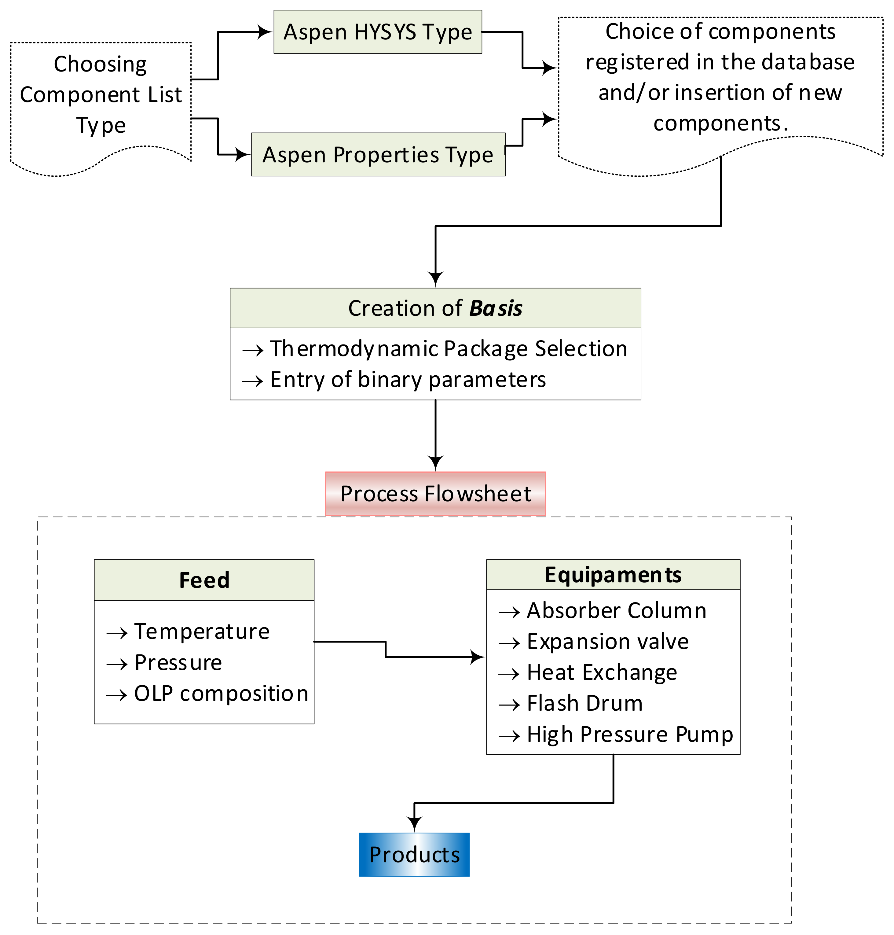
2.1. Simulation Methodology

The organic liquid products (OLP) obtained through the thermal catalytic cracking of palm oil at 450 °C, 1.0 atm, using 10% (wt.) Na2CO3 as a catalyst, at a pilot scale, are a complex mixture of hydrocarbons (alkanes, alkenes, cycloalkanes, and aromatics) and oxygenates (carboxylic acids, ketones, and alcohols) [9]. Since high-pressure phase equilibrium data for the binary pairs of OLP-compounds-i/CO2 are scarce, the chemical composition of OLP determined through GC-MS identified approximately 90% (area.) hydrocarbons and 10% (area.) oxygenates, and found that acidity is mainly due to the presence of carboxylic acids, whereby OLP has been described by the key compounds of hydrocarbons (decane, undecane, tetradecane, pentadecane, hexadecane, and octadecane) and oxygenates (palmitic acid, oleic acid) [59,60]. The simulations were performed by selecting the unit operation multistage countercurrent absorber, as the dissolution/solubilization of gases (CO2) in liquids (OLP) is a function of state conditions (P, T), whereby a fraction of the coexisting liquid phase dissolves in the gas phase, such as with a gas (CO2)–liquid (OLP) equilibrium behavior. In the multistage countercurrent absorber column, the fraction collected at the top stream is the extract, that is, a phase rich in SC-CO2, containing the more soluble compounds, in this case, the hydrocarbons (decane, undecane, tetradecane, pentadecane, hexadecane, and octadecane), while the fraction collected at the bottom stream is the raffinate, that is, a phase rich in OLP or CO2, containing the less soluble compounds, in this case, the oxygenates (palmitic acid, oleic acid).
The P-xCO2,yCO2 diagram for the high-pressure phase equilibrium data for the binary pairs of OLP-compounds-i + CO2 (decane + CO2, undecane + CO2, tetradecane + CO2, pentadecane + CO2, hexadecane + CO2, palmitic acid + CO2, and oleic acid + CO2) described in the literature [61,62,63,64,65,66,67,68], shows that phase envelop of all the binary pairs of hydrocarbons-i + CO2 (decane + CO2, undecane + CO2, tetradecane + CO2, pentadecane + CO2, hexadecane + CO2) closes between 12.654 and 16.354 MPa and the phase envelope of binary pairs of hydrocarbons-i + CO2 limits the separation of hydrocarbons and carboxylic acids (oxygenates), as shown in Figure 1. In this context, the simulation should be performed between 12.654 and 16.354 MPa. In fact, the state conditions (P, T) to be chosen should take into account not only the solubility of OLP in the SC-CO2, a physicochemical property associated with the solvent-to-feed ratio (S/F), but also the fraction of carboxylic acids into OLP dissolved in SC-CO2 (selectivity). The higher the solubility of OLP in the SC-CO2, the lower the solvent-to-feed ratio (S/F) and the lower the selectivity. On the other hand, the lower the solubility of OLP in the SC-CO2, the higher the solvent-to-feed ratio (S/F) and the higher the selectivity. Therefore, a compromise must be found between the solubility of OLP in the SC-CO2 and the selectivity of OLP compounds in SC-CO2, that is, between the solvent-to-feed ratio (S/F) and the fraction of carboxylic acids into OLP dissolved in SC-CO2, as the deoxygenation aims to obtain extracts, that is, OLP containing very low concentrations carboxylic acids and raffinates with high concentrations of carboxylic acids. On the basis of the analysis of high-pressure phase equilibrium data for the binary pairs OLP-compounds-i + CO2, the state conditions chosen were p = 14.0 MPa and 333 K ≤ T ≤ 350 K.
The OLP deoxygenation process, using SC-CO2 as a solvent, was simulated using Aspen-HYSYS 8.6 (Aspen One, 2015). The simulations were performed by selecting the multistage countercurrent absorber/stripping unit operation because of its similarities and/or theoretical thermodynamic fundamentals relating to the solubility of gas in liquids, as the phase equilibrium behaves like a gas–liquid coexisting phase, as described elsewhere [59,60]. Aspen-HYSYS 8.6 computes the countercurrent multistage absorber column unit’s operations by applying the inside-out algorithm to solve, simultaneously, the materials and energies balances that are stage-to-stage coupled with a rigorous thermodynamic model. The RK-Aspen EOS with the adjusted binary interaction parameters was selected as the fluid package to compute the mixture properties for the multicomponent mixture OLP/SC-CO2 [59,60].
Organic liquid products obtained through the thermal catalytic cracking of palm oil at 450 °C, 1.0 atmosphere, with 10% (wt.) Na2CO3 as a catalyst, containing 89.24% (area.) hydrocarbons and 10% (area.) oxygenates were used as the feed stream [9,59]. The operating conditions in the simulation of the OLP deoxygenation process, using SC-CO2 as a solvent, with the help of the chemical process simulator Aspen-HYSYS 8.6 (Aspen One, 2015), are described in Table 1.
The process performance was evaluated on the basis of the yields of hydrocarbons and oxygenates, as well as the recovery of hydrocarbons, olefins, oxygenates, and carboxylic acid in the OLP fraction process streams. The yield and recovery of process stream i are computed as follows:
Y i e l d i % = m i ˙ m ˙ O L P
R e c o v e r y j % = ω j m i ˙ ω j , O L P m ˙ O L P
where m ˙ i and m ˙ O L P are the mass flow rates of process stream i and the OLP feed stream, and ω j and ω j , O L P are the mass fractions of hydrocarbons or oxygenates chemical functions of process stream i and the OLP feed stream.

2.2. Simulation Methodology and Procedures

The Aspen-HYSYS chemical process simulator uses, for all separation processes and procedures, rigorous calculations for the mass and energy balances, providing a strong basis for simulations involving unit operations, thermodynamics, and chemical reactors. The software has a huge amount of flexibility and can simulate different chemical processes according to the user’s assembly [59].
In this work, Aspen-HYSYS was used to perform simulations aiming to deacidify OLP in a multistage absorber column, in countercurrent mode, using SC-CO2 as a solvent. In general, process simulations using Aspen-HYSYS 8.4 consist of in the following steps [59]: 1—the selection of the component list type; 2—the formulation of the list of components; 3—the basis formulation; 4—the flowsheet assembly of the process, as shown in Figure 2.

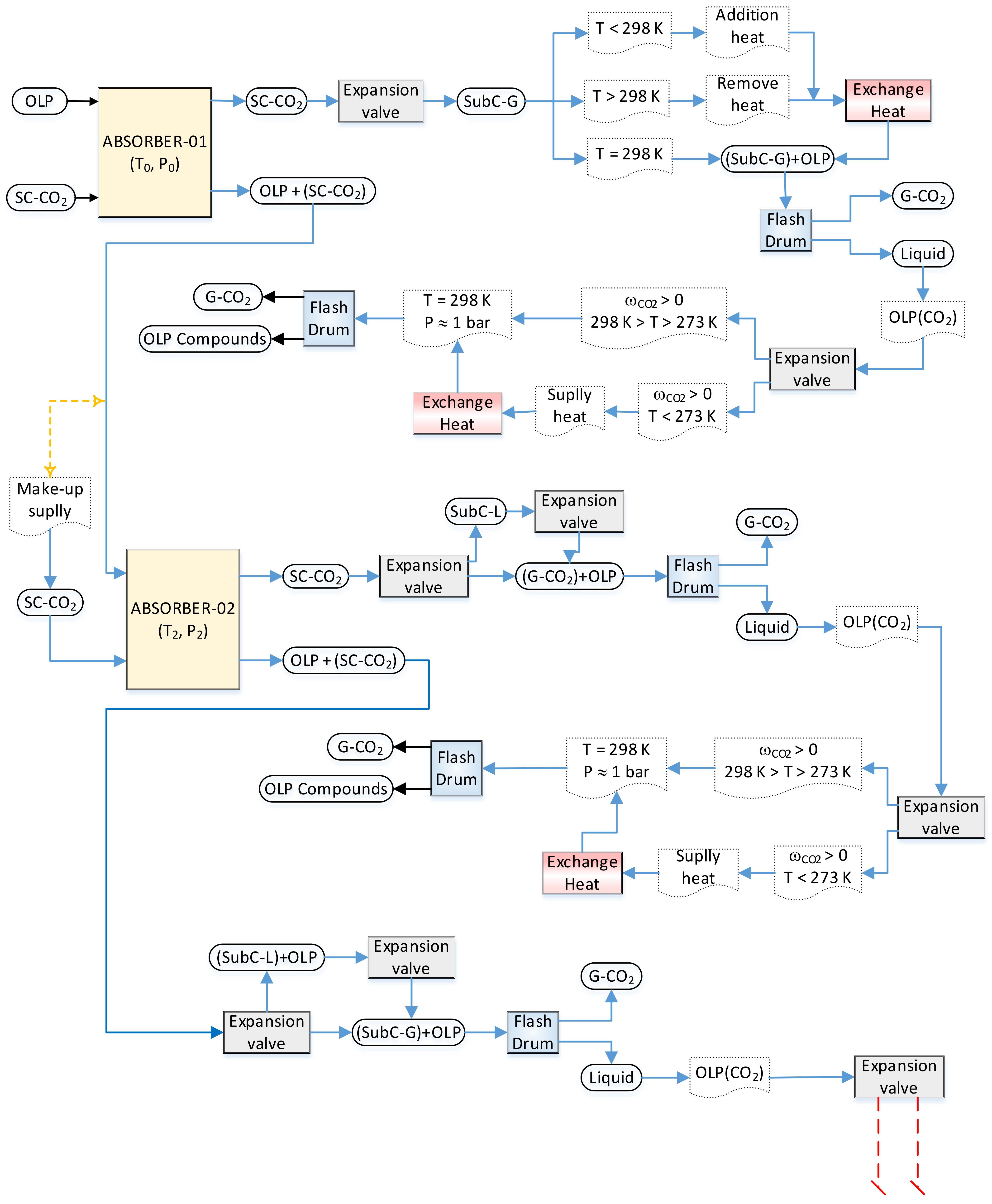
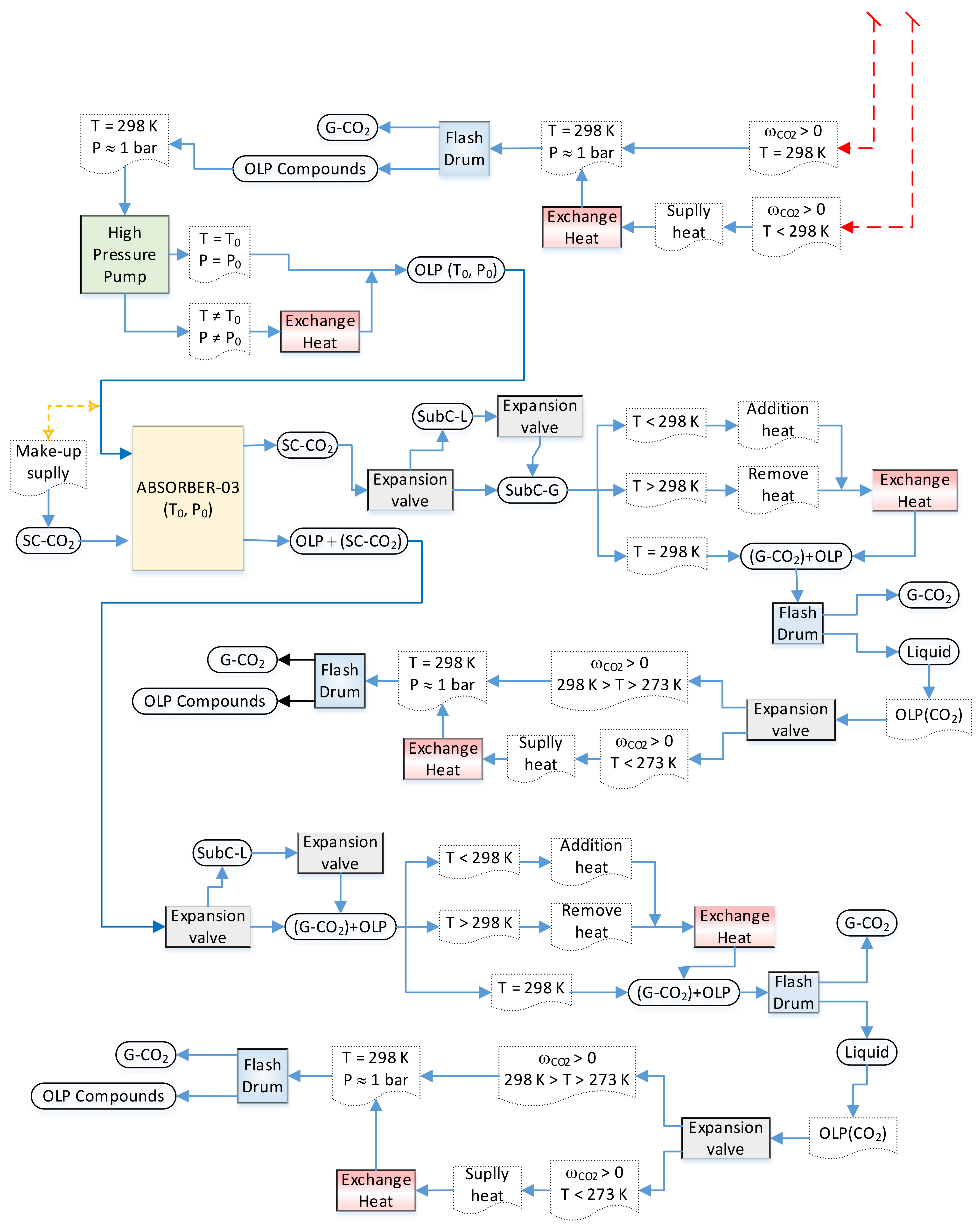
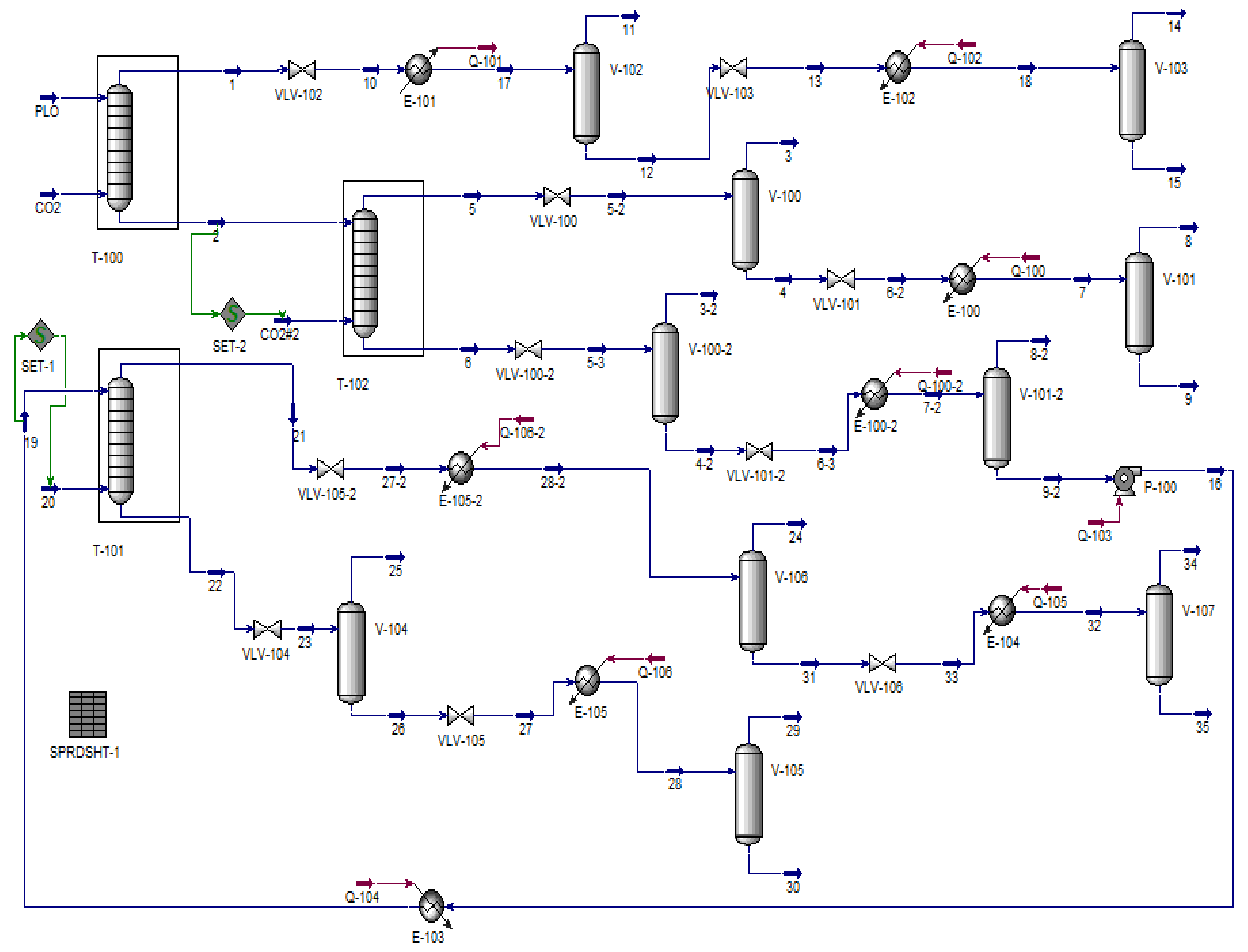
2.3. Simulation Process Flowsheet Strategy

In a previous work, Costa et al. [60] provided the thermodynamic data basis and the EOS modeling to simulate the deoxygenation of OLP obtained through the thermal-catalytic cracking of palm oil at 450 °C, 1.0 atm, with 10% (wt.) Na2CO3 [9], making it possible to perform the process simulation of OLP deoxygenation with a multistage countercurrent absorber with SC-CO2 as a solvent using the process simulator Aspen-HYSYS. Costa et al. [59], simulated the fractionation of OLP obtained through the thermal catalytic cracking of palm oil at 450 °C, 1.0 atm, with 10% (wt.) Na2CO3 in countercurrent multistage absorber columns using CO2 as a solvent with Aspen-HYSYS, proposing flowsheets with 01 (one) absorber column (flowsheet I) and 02 (two) absorber columns (flowsheet II), where the bottom stream of first absorber column was used as a feed in the second absorber column using SC-CO2 as solvent, as described in detail in the literature [59]. This work addresses a new flowsheet, consisting of 03 (three) absorber columns, aiming to improve the deacidification of organic liquid products.
The algorithm, shown in the sub-flowsheets I and II illustrated in Figure 3 and Figure 4, respectively, describes in detail the procedures necessary to perform the simulation of OLP deacidification/deoxygenation, with the OLP obtained through the thermal catalytic cracking of palm oil at 450 °C, 1.0 atm, with 10% (wt.) Na2CO3 as a catalyst, in multistage countercurrent absorber columns using SC-CO2 as a solvent. Initially, OLP enters at the top of absorber-01 and SC-CO2 at the bottom in countercurrent mode. After equilibrium is achieved at a particular state condition (T1, P1), 02 (two) coexisting phases, including a dense gaseous phase, rich in SC-CO2 and containing the highly soluble/dissolved compounds (hydrocarbons) of OLP, and a liquid phase, poor in OLP, containing large amounts of dissolved CO2, are present. The dense gaseous phase exits the top of absorber-01, while the liquid phase exits the bottom of absorber-01. In order to remove CO2 in the top stream, it is necessary not only perform a state transition of SC-CO2 → G-CO2, but also guarantee that light OLP compounds are no longer dissolved in G-CO2. In this context, it is necessary to change the state conditions by adding an expansion valve followed by a heat exchanger to remove or add thermal energy, if necessary, to bring the temperature close to ambient conditions, as well as a flash drum to separate subcritical gaseous CO2 and/or gaseous CO2 from OLP. If the state conditions of the OLP that leaves the bottom of flash drum still permits dissolved CO2 to coexist in the OLP, then it is necessary to add an expansion valve to bring the pressure close to ambient conditions, followed by a heat exchanger to add thermal energy, if necessary, to bring the temperature close to ambient conditions (T = 298 K), as well as a flash drum to separate gaseous CO2 from the OLP. If all the gaseous CO2 is released at the top of the flash drum by ambient conditions (T ≈ 298 K, p ≈ 1.0 bar) and the OLP that leaves the bottom of the flash drum no longer contains dissolved CO2, then the separation step is completed.
The liquid that exits the bottom of absorber-01, poor in OLP, containing large amounts of dissolved CO2, enriched by the lowly soluble/dissolved compounds (oxygenates) of OLP enters at the top of absorber-02 as the feed, while fresh SC-CO2 (make-up) enters at the bottom of absorber-02 at the same state condition of the liquid stream (T2, P1). After equilibrium is achieved (T2, P1), 02 (two) coexisting phases, including a dense gaseous phase, rich in SC-CO2, containing the highly soluble/dissolved compounds (hydrocarbons) of OLP, and a liquid phase, poor in OLP, containing large amounts of dissolved CO2, are present. The dense gaseous phase exits the top of absorber-02, while the liquid phase exits the bottom of absorber-02. In order to remove CO2 in the top stream, it is necessary not only perform a state transition of SC-CO2 → G-CO2, but also guarantee that light OLP compounds are no longer dissolved in G-CO2. Adding an expansion valve makes it possible to change the state conditions, while a heat exchanger can be used to remove or add thermal energy, if necessary, to bring the temperature close to ambient conditions. Afterwards, a flash drum is added to separate the subcritical gaseous CO2 and/or gaseous CO2 from the OLP. If the OLP that leaves the bottom of the flash drum still contains dissolved CO2, then an expansion valve is added to bring the pressure close to ambient conditions, followed by a heat exchanger to supply thermal energy, if necessary, to bring the temperature close to ambient conditions (T = 298 K), as well as a flash drum to separate gaseous CO2 from the OLP. If all the gaseous CO2 is released at the top of the flash drum by ambient conditions (T ≈ 298 K, p ≈ 1.0 bar) and the OLP that leaves the bottom of the flash drum no longer contains dissolved CO2, then the separation step is completed.
The liquid phase leaving the bottom of absorber-02, poor in OLP, contains large amounts of dissolved CO2 that must be removed and separated from the OLP. In order to remove CO2 in the bottom stream, it is necessary to change the state conditions to diminish the solubility of the CO2 in the OLP. Adding an expansion valve makes it possible to change the state conditions of soluble/dissolved CO2 from liquid to subcritical gaseous CO2 and/or gaseous CO2 (L-CO2 → SC-CO2/G-CO2). Afterwards, a flash drum is added to separate the subcritical gaseous CO2 and/or gaseous CO2 from the OLP. If the OLP that leaves the bottom of the flash drum still contains dissolved CO2, then an expansion valve is added to bring the pressure close to ambient conditions, followed by a heat exchanger to supply thermal energy, if necessary, to bring the temperature close to ambient conditions (T = 298 K), as well as a flash drum to separate gaseous CO2 from the OLP. If all the gaseous CO2 is released at the top of the flash drum by ambient conditions (T ≈ 298 K, p ≈ 1.0 bar), but considerable amounts of OLP still leaves the bottom of the flash drum, even though it no longer contains dissolved CO2, another absorber should be added to the flowsheet. In order to bring the OLP to the state conditions (T1, P1) of absorber-03, a high-pressure pump is added after the flash drum bottom stream, followed by a heat exchanger to supply thermal energy. The OLP enters at the top of absorber-03 as the feed, while fresh SC-CO2 (make-up) enters at the bottom of absorber-03 at the same state condition of the liquid stream (T1, P1). After equilibrium is achieved (T1, P1), 02 (two) coexisting phases, including a dense gaseous phase, rich in SC-CO2, containing the highly soluble/dissolved compounds (hydrocarbons) of the OLP, and a liquid phase, poor in OLP, containing large amounts of dissolved CO2, are present. The dense gaseous phase exits the top of absorber-03, while the liquid phase exits the bottom of absorber-03. In order to remove CO2 in the top stream, it is necessary not only perform a state transition of SC-CO2 → G-CO2, but also guarantee that light OLP compounds are no longer dissolved in G-CO2. Adding an expansion valve makes it possible to change the state conditions, and a heat exchanger can be added to remove or add thermal energy, if necessary, to bring the temperature close to ambient conditions. Afterwards, a flash drum is added to separate the gaseous CO2 from the OLP. If the OLP that leaves the bottom of the flash drum still contains dissolved CO2, then an expansion valve is added to bring the pressure close to ambient conditions, followed by a heat exchanger to supply thermal energy, if necessary, to bring the temperature close to ambient conditions (T = 298 K), as well as a flash drum to separate gaseous CO2 from the OLP. If all the gaseous CO2 is released at the top of the flash drum by ambient conditions (T ≈ 298 K, p ≈ 1.0 bar) and the OLP that leaves the bottom of the flash drum no longer contains dissolved CO2, then the separation step is completed.
The liquid phase leaving the bottom of absorber-03, poor in OLP, contains large amounts of dissolved CO2 that must be removed and separated from OLP. In order to remove CO2 in the bottom stream, it is necessary to change the state conditions to diminish the solubility of the CO2 in the OLP. Adding an expansion valve makes it possible to change the state conditions of soluble/dissolved CO2 from liquid to gaseous CO2 (L-CO2 → G-CO2). Afterwards, a flash drum is added to separate the gaseous CO2 from the OLP. If the OLP that leaves the bottom of the flash drum still contains dissolved CO2, then an expansion valve is added to bring the pressure close to p ≈ 1.0 bar, followed by a heat exchanger to supply thermal energy, if necessary, to bring the temperature close to T ≈ 298 K, as well as a flash drum to separate gaseous CO2 from the OLP. If all the gaseous CO2 is released at the top of the flash drum by ambient conditions (T ≈ 298 K, p ≈ 1.0 bar) and the OLP that leaves the bottom of the flash drum no longer contains dissolved CO2, then the separation step is completed.

3. Results and Discussions

3.1. Process Simulation

Process Flowsheet

The proposed flowsheet illustrated in Figure 5 consists of 03 absorber columns, 10 expansions valves, 10 flash drums, 08 heat exchanges, 01 high-pressure pump, and 02 make-ups of CO2, aiming to optimize the deacidification of organic liquid products.
Table 2 shows the material (molar and mass flow rates) and energy balances (heat flow rates), fractions of gas phases, as well as the state conditions (T, P) for all the process streams for the simulation of the OLP deoxygenation process in multistage countercurrent absorber columns using CO2 as a solvent, with Aspen-HYSYS 8.6 (Aspen One, 2015) as the simulator, expressed on a CO2 basis, at 333 K, 140 bar, and (S/F) = 17; at 350 K, 140 bar, and (S/F) = 25; and at 333 K, 140 bar, and (S/F) = 38.
In addition, Supplementary Tables S1–S3 provide detailed information on the process conditions, mass flow rates, gaseous fractions, recoveries of hydrocarbons and oxygenates in extract and raffinates, as well as the chemical composition, expressed on a solvent-free basis, of the hydrocarbons and oxygenates of OLP in the feed, top, and bottom streams of absorber columns T-100, T-102, and T-101 for the simulation of the OLP deoxygenation process in multistage countercurrent absorber columns using CO2 as a solvent, with Aspen-HYSYS 8.6 (Aspen One, 2015) as the simulator, at 333 K, 140 bar, and (S/F) = 17; at 350 K, 140 bar, and (S/F) = 25; and at 333 K, 140 bar, and (S/F) = 38.
Stream 1, leaving the top of absorber column T-100, rich in carbon dioxide in a supercritical state, with a gaseous phase solubility yCO2,OLP = 0.9597, which is very close to yCO2,Undecane = 0.9518 at 344.5 K and 13.4 MPa for the high-pressure phase equilibria of binary system n-undecane + CO2 [62], flows through the expansion valve (VLV-102), causing not only a decrease in pressure and temperature, but also a phase change from a supercritical to a sub-critical gaseous state, making it possible to separate CO2 in the gaseous state from organic liquid products. However, if the solubility of dissolved the OLP compounds in gaseous CO2 is still low but not zero, due to high temperatures at the exit of expansion valve, a heat exchanger (E-101) is placed after the expansion valve to diminish the temperature, thus making it possible to complete the separation of gaseous CO2 and the dissolved OLP compounds within the flash drum (V-102), since the solubility of dissolved OLP in CO2 tends to zero. The bottom stream of the flash drum (V-102), rich in OLP compounds, still contains dissolved CO2, thus making it necessary to insert another expansion valve (VLV-103) at the exit of the flash drum (V-102), causing a decrease in pressure and temperature. However, if the temperature is too low, then that may solidify the condensed OLP compounds, and so a second heat exchanger (E-102) should be placed after the expansion valve to supply thermal energy in order to increase the temperature, maintaining the OLP compounds in the liquid state, thus making it possible to complete the separation of gaseous CO2 and the condensed OLP compounds within the flash drum (V-103), since the solubility of dissolved CO2 in OLP tends to zero.
The OLP at the top stream of absorber column T-100, expressed on a solvent-free basis, obtained from bottom stream 15, after the separation and/or degassing of gaseous CO2 in the flash drums V-102 and V-103, present as their chemical composition 96.95% (area.) hydrocarbons with 39.14% (area.) alkanes, 36.39% (area.) alkenes (olefins), and 21.42% (area.) naphthene, as well as 3.05% (area.) oxygenates. By comparing the composition of the OLP in stream 15 with that of a kerosene-like fraction, containing 93.63% (area.) hydrocarbons (42.62% alkanes, 24.89% alkenes, and 26.12% naphthene) and 6.37% (area.) oxygenates, obtained through the distillation of organic liquid products after the thermal catalytic cracking of dehydrated residual fat, oils, and grease (FOG) from grease traps at 450 °C, 1.0 atm, with 10% (wt.) Na2CO3, at a pilot scale [19], we see that the OLP fraction of the extract in bottom stream 15 of absorber column T-100 resembles the chemical composition of kerosene, with lower levels of alkanes and oxygenates. In addition, the recovery of OLP, expressed on a solvent-free basis, obtained in bottom stream 15 was 36.65%, as shown in Table 3.
Stream 2, leaving the bottom of absorber column T-100, rich in CO2 dissolved in OLP, with a liquid phase solubility xCO2,OLP = 0.9281, which is very close to xCO2,Undecane = 0.9161 at 344.5 K and 13.4 MPa for the high-pressure phase equilibria of binary system n-undecane + CO2 [62], enters the top of absorber column T-102 as partially acidified hydrocarbons, containing 84.78% (area.) hydrocarbons (43.54% alkanes, 18.95% alkenes, and 22.29% naphthene) and 15.22% (area.) oxygenates. Fresh CO2, supplied as a make-up gas, enters the bottom of absorber column T-102 in order to achieve the solvent-to-feed ratio of (S/F) = 38. Stream 5, leaving the top of absorber column T-102, rich in carbon dioxide in the supercritical state, with a gaseous phase solubility yCO2,OLP = 0.9817, which is very close to yCO2,Tetradecane = 0.9870 at 344.5 K and 13.95 MPa for the high-pressure phase equilibria of binary system n-undecane + CO2 [62], flows through the expansion valve (VLV-100), changing the state conditions (T = 294.6 K, p = 40 bar), causing a phase change from a supercritical to a gaseous state, making it possible to separate CO2 in the gaseous state is there the reference citationfrom organic liquid products inside the flash drum (V-100). The bottom stream of the flash drum (V-100), rich in OLP compounds, still contains dissolved CO2, thus making it necessary to insert another expansion valve (VLV-101) at the exit of the flash drum (V-100), causing a decrease in pressure and temperature (T = 236.0 K, p = 1.5 bar). In cases where a drastic decrease in the temperature takes place because of the Joule–Thomson effect, which may solidify the OLP compounds, a heat exchanger (E-100) is placed after the expansion valve to supply thermal energy to bring the temperature to ambient conditions (T = 298 K), thus making it possible to complete the separation of gaseous CO2 and the dissolved OLP compounds within the flash drum (V-101), since the solubility of dissolved OLP in CO2 tends to zero.
The OLP at the top stream of absorber column T-102, expressed on a solvent-free basis, obtained from bottom stream 9, after the separation and/or degassing of gaseous CO2 in the flash drums V-100 and V-101, contains 92.78% (area.) hydrocarbons (46.53% alkanes, 21.75% alkenes, and 24.49% naphthene) and 7.22% (area.) oxygenates. By comparing the composition of OLP in stream 9 with that of a gasoline-like fraction containing 92.30% (area.) hydrocarbons (21.52% alkanes, 37.51% alkenes, and 33.27% naphthene) and 7.70% (area.) oxygenates, obtained through the distillation of organic liquid products after the thermal catalytic cracking of palm oil at 450 °C, 1.0 atm, with 20% (wt.) Na2CO3, at a pilot scale [69], we see that the OLP fraction of the extract in bottom stream 9 of absorber column T-102 resembles the chemical composition of gasoline, with lower levels of alkanes and oxygenates. In addition, the recovery of OLP, expressed on a solvent-free basis, obtained from bottom stream 9 was 40.77%, as shown in Table 3.
Stream 6, leaving the bottom of absorber column T-102, rich in dissolved CO2 into OLP, with a liquid phase solubility xCO2,OLP = 0.9072, which is very close to xCO2,Undecane = 0.9161 at 344.5 K and 13.4 MPa for the high-pressure phase equilibria of binary system n-undecane + CO2 [62], flows through the expansion valve (VLV-100-2), changing the state conditions, causing a phase change from a supercritical (T = 371 K, p = 140 bar) to a sub-critical gaseous state (T = 319 K, p = 50 bar), making it possible to separate CO2 in the gaseous state from organic liquid products inside the flash drum (V-100-2). The bottom stream of the flash drum (V-100-2), rich in OLP compounds, still contains dissolved CO2, thus making it necessary to insert another expansion valve (VLV-101-2) at the exit of the flash drum (V-100-2), causing a decrease in pressure (p = 1.5 bar) and temperature (T = 291 K). In order to bring the temperature to ambient conditions, a heat exchanger (E-100-2) is placed after the expansion valve to supply thermal energy, thus making it possible to complete the separation of gaseous CO2 and the dissolved OLP compounds within the flash drum (V-101-2), since the solubility of dissolved OLP in CO2 tends to zero. As the stream leaving the bottom of the flash drum (V-101-2) still contains large amounts of OLP compounds, a third absorber column is added to the flowsheet to deacidify the OLP compounds. Stream 9-2 is compressed with the help of a high-pressure pump (P-100) to bring the OLP to the state conditions of absorber column T-101 (T = 333 K, p = 140 bar). After the high-pressure pump, the state condition of stream 16 is 303 K and 140 bar, thus making it necessary to add a heat exchanger (E-103) to supply thermal energy to bring the temperature to 333 K. Stream 19 (T = 333 K, p = 140 bar) enters the top of absorber column T-101, while fresh CO2 supplied as a make-up gas (SET-1) enters the bottom of absorber column T-101 at 333 K and 140 bar.
Stream 21, leaving the top of absorber column T-101, rich in CO2 in the supercritical state, with a gaseous phase solubility yCO2,OLP = 0.9869, which is very close to yCO2,Tetradecane = 0.9870 at 344.5 K and 13.95 MPa for the high-pressure phase equilibria of binary system n-undecane + CO2 [63], flows through the expansion valve (VLV-105-2), causing a phase change from a supercritical to a gaseous state, making it possible to separate CO2 in the gaseous state from organic liquid products. If the temperature is lower than 298 K, a heat exchanger (E-105-2) is placed after the expansion valve to bring the temperature to 298 K, thus making the separation of gaseous CO2 and the dissolved OLP compounds within the flash drum possible (V-106). If the bottom stream of the flash drum (V-106), rich in OLP compounds, still contains dissolved CO2, it is necessary to insert another expansion valve (VLV-106) at the exit of the flash drum (V-106), causing a decrease in pressure and temperature. However, if the temperature is too low, then that may solidify the condensed OLP compounds, and a second heat exchanger (E-104) should be placed after the expansion valve (VLV-106) to supply thermal energy, in order to increase the temperature, maintaining the OLP compounds in the liquid state, thus making it possible to complete the separation of gaseous CO2 and the condensed OLP compounds within the flash drum (V-107), since the solubility of dissolved CO2 in OLP tends to zero.
Stream 22, leaving the bottom of absorber column T-101, rich in dissolved CO2 into OLP, with a liquid phase solubility xCO2,OLP = 0.9323, which is very close to xCO2,Undecane = 0.9161 at 344.5 K and 13.4 MPa for the high-pressure phase equilibria of binary system n-undecane + CO2 [62], flows through the expansion valve (VLV-104), causing a phase change from a supercritical (T = 333 K, p = 140.0 bar) to a gaseous state (T = 298 K, p = 60 bar), making it possible to separate CO2 in the gaseous state from organic liquid products inside the flash drum (V-104). The bottom stream of the flash drum (V-104), rich in OLP compounds, still contains dissolved CO2, thus making it necessary to insert another expansion valve (VLV-105) at the exit of the flash drum (V-104), causing a decrease in pressure (p = 1.5 bar) and temperature (T = 191.0 K). In order to bring the temperature to ambient conditions, a heat exchanger (E-105) is placed after the expansion valve to supply thermal energy, thus making it possible to complete the separation of gaseous CO2 and the dissolved OLP compounds within the flash drum (V-105), since the solubility of dissolved OLP in CO2 tends to zero at 298 K and 1.5 bar. The simulated gas–liquid high-pressure equilibrium in the exit of absorber columns T-100, T-102, and T-101, given by the yCO2,OLP and xCO2,OLP of streams 1, 2, 3, 6, 21, and 22, are defined according to high-pressure equilibrium data for the binary pairs of OLP-compounds-i + CO2 (decane + CO2, undecane + CO2, tetradecane + CO2, pentadecane + CO2, hexadecane + CO2) described in the literature [61,62,63,64,65].
The OLP at the bottom stream of absorber column T-102, expressed on a solvent-free basis, obtained from bottom stream 9-2, after the separation and/or degassing of gaseous CO2 in the flash drums V-100-2 and V-101-2, enriched on oxygenates, present as their composition 70.34% (area.) hydrocarbons (38.15% alkanes, 13.88% alkenes, and 18.31% naphthene) and 29.66% (area.) oxygenates, while stream 35 at the bottom flash drum (V-107), expressed on a solvent-free basis, contains 83.85% (area.) hydrocarbons and 16.15% (area.) oxygenates. Stream 30 at the bottom flash drum (V-105), expressed on a solvent-free basis, enriched in oxygenates, contains 67.34% (area.) hydrocarbons and 32.66% (area.) oxygenates. The recovery of OLP, expressed on a solvent-free basis, obtained from bottom stream 35 of the flash drum (V-107) was 4.07%, as shown in Table 3.
The simulated chemical composition of OLP in stream 15, expressed on a CO2-free basis, shows a yield of 36.65% with 96.95% (wt.) hydrocarbons and 3.05% (wt.) oxygenates. A decrease in the oxygenate content in feed OLP could be observed from 10% (wt.), with 2.63% (wt.) carboxylic acids, to 3.05% (wt.) oxygenates, with 0.52% (wt.) carboxylic acids [59], showing that the fraction of carboxylic acids in OLP dissolved into SC-CO2 was very low. This is according to high-pressure phase equilibrium data for the binary systems of palmitic acid + CO2 [66,67], and oleic acid + CO2 [68].
The simulated chemical composition of OLP in stream 9, expressed on a CO2-free basis, shows a yield of 40.77% with 92.78% (wt.) hydrocarbons and 7.22% (wt.) oxygenates. A decrease in the oxygenate content in RAF1 could be observed from 15.22% (wt.), with 3.85% (wt.) carboxylic acids, to 7.22% (wt.) oxygenates, with 1.47% (wt.) carboxylic acids [59], showing that the fraction of carboxylic acids in OLP dissolved into SC-CO2 was very low. This is according to high-pressure phase equilibrium data for the binary systems of palmitic acid + CO2 [66,67] and oleic acid + CO2 [68]. Finally, it can be observed in Table 3 that 81.49% (wt.) of feed OLP was recovered in the top streams of absorbers T-100, T-102, and T-101, showing that deacidified OLP have chemical compositions similar to kerosene-like fractions obtained through the distillation of organic liquid products after the thermal catalytic cracking of dehydrated residual fat, oils, and grease (FOG) from grease traps at 450 °C, 1.0 atm, with 10% (wt.) Na2CO3, at a pilot scale [19], and gasoline-like fractions obtained through the distillation of organic liquid products after the thermal catalytic cracking of palm oil at 450 °C, 1.0 atm, with 20% (wt.) Na2CO3, at a pilot scale [69].

4. Conclusions

This work addresses a new flowsheet, consisting of three absorber columns, aiming to improve the deacidification of organic liquid products (OLP) in multistage countercurrent absorber/stripping columns using SC-CO2 as a solvent, with the Aspen-Hysys system.
The algorithm, shown in sub-flowsheets I and II, describes in detail the procedures necessary to perform the simulation of OLP deacidification/deoxygenation, obtained through the thermal catalytic cracking of palm oil at 450 °C, 1.0 atm, with 10% (wt.) Na2CO3 as a catalyst, in multistage countercurrent absorber columns using SC-CO2 as a solvent.
The simulation shows that 81.49% of OLP could be recovered and that the concentrations of hydrocarbons in the extracts of absorber-01 and absorber-02 were 96.95 and 92.78% (wt.) on a solvent-free basis, while the bottom stream of absorber-03 was enriched in oxygenate compounds with concentrations up to 32.66% (wt.) on a solvent-free basis, showing that organic liquid products (OLP) was deacidified and SC-CO2 was able to deacidify OLP and obtain fractions with lower olefin contents.

Supplementary Materials

The following supporting information can be downloaded at: https://www.mdpi.com/article/10.3390/molecules27072211/s1. Table S1: Process conditions, mass flow rates, gaseous fractions, and recoveries of hydrocarbons and oxygenates in extracts and raffinates, as well as chemical composition, expressed on a solvent-free basis, of hydrocarbons and oxygenates of OLP in feed, top, and bottom streams of absorber columns T-100 for the simulation of the OLP deoxygenation process in multistage countercurrent absorber columns using CO2 as a solvent, with Aspen-HYSYS 8.6 (Aspen One, 2015) as the simulator, at 333 K, 140 bar, and (S/F) = 17. Table S2: Process conditions, mass flow rates, gaseous fractions, and recoveries of hydrocarbons and oxygenates in extracts and raffinates, as well as chemical composition, expressed on a solvent-free basis, of hydrocarbons and oxygenates of OLP in feed, top, and bottom streams of absorber columns T-102 for the simulation of the OLP deoxygenation process in multistage countercurrent absorber columns using CO2 as a solvent, with Aspen-HYSYS 8.6 (Aspen One, 2015) as the simulator, at 350 K, 140 bar, and (S/F) = 25. Table S3: Process conditions, mass flow rates, gaseous fractions, and recoveries of hydrocarbons and oxygenates in extracts and raffinates, as well as chemical composition, expressed on a solvent-free basis, of hydrocarbons and oxygenates of OLP in feed, top, and bottom streams of absorber columns T-101 for the simulation of the OLP deoxygenation process in multistage countercurrent absorber columns using CO2 as a solvent, with Aspen-HYSYS 8.6 (Aspen One, 2015) as the simulator, at 333 K, 140 bar, and (S/F) = 38.

Author Contributions

The individual contributions of all the co-authors are provided as follows: M.R.d.S.J. contributed with formal analysis and writing—original draft preparation, E.C.C. contributed with formal analysis and writing—original draft preparation, M.P.d.S. contributed with computation of binary interaction parameters with Aspen-HYSYS and simulations, C.C.F. contributed with graphics and flowsheets, L.P.B. contributed with graphics and flowsheets, D.A.R.d.C. contributed with thermal-catalytic cracking experiments, M.C.S. contributed with thermal-catalytic cracking experiments, A.d.A.M. contributed with thermal-catalytic cracking experiments, S.A.P.d.M. contributed with OLP chemical composition calculations, S.D.J. contributed with OLP chemical analysis, L.E.P.B. contributed with experimental design, M.E.A. contributed with supervision, conceptualization, and data curation, and N.T.M. contributed with supervision, conceptualization, and data curation. All authors have read and agreed to the published version of the manuscript.

Funding

This research received no external funding.

Acknowledgments

I would like to acknowledge Gerd Brunner, former Head of Thermal Separation Process Institute at TUHH, for his marvelous contribution to the fractionation of liquid mixtures in countercurrent columns using supercritical carbon dioxide as a solvent.

Conflicts of Interest

The authors declare no conflict of interest.

Sample Availability

Not available.

References

  1. Junming, X.; Jianchun, J.; Yunjuan, S.; Jie, C. Production of hydrocarbon fuels from pyrolysis of soybean oils using a basic catalyst. Bioresour. Technol. 2010, 101, 9803–9806. [Google Scholar]
  2. Taufiqurrahmi, N.; Bhatia, S. Catalytic cracking of edible and non-edible oils for the production of biofuels. Energy Environ. Sci. 2011, 4, 1087–1112. [Google Scholar] [CrossRef]
  3. Buzetzki, E.; Sidorová, K.; Cvengrošová, Z.; Cvengroš, J. Effects of oil type on products obtained by cracking of oils and fats. Fuel Process. Technol. 2011, 92, 2041–2047. [Google Scholar] [CrossRef]
  4. Buzetzki, E.; Sidorová, K.; Cvengrošová, Z.; Kaszonyi, A.; Cvengroš, J. The influence of zeolite catalysts on the products of rapeseed oil cracking. Fuel Process. Technol. 2011, 92, 1623–1631. [Google Scholar] [CrossRef]
  5. Yu, F.; Gao, L.; Wang, W.; Zhang, G.; Ji, J. Bio-fuel production from the catalytic pyrolysis of soybean oil over Me-Al-MCM-41 (Me = La, Ni or Fe) mesoporous materials. J. Anal. Appl. Pyrolysis 2013, 104, 325–329. [Google Scholar] [CrossRef]
  6. Doronin, V.P.; Potapenko, O.V.; Lipin, P.V.; Sorokina, T.P. Catalytic cracking of vegetable oils and vacuum gas oil. Fuel 2013, 106, 757–765. [Google Scholar] [CrossRef]
  7. Mota, S.A.P.; Mancio, A.A.; Lhamas, D.E.L.; de Abreu, D.H.; da Silva, M.S.; Santos, W.G.d.; de Castro, D.A.R.; de Oliveira, R.M.; Araújo, M.E.; Borges, L.E.P.; et al. Production of green diesel by thermal catalytic cracking of crude palm oil (Elaeis guineensis Jacq) in a pilot plant. J. Anal. Appl. Pyrolysis 2014, 110, 1–11. [Google Scholar] [CrossRef]
  8. Mâncio, A.A.; da Costa, K.M.B.; Ferreira, C.C.; Santos, M.C.; Lhamas, D.E.L.; da Mota, S.A.P.; Leão, R.A.C.; de Souza, R.O.M.A.; Araújo, M.E.; Borges, L.E.P.; et al. Process analysis of physicochemical properties and chemical composition of organic liquid products obtained by thermochemical conversion of palm oil. J. Anal. Appl. Pyrolysis 2017, 123, 284–295. [Google Scholar] [CrossRef]
  9. Mancio, A.A.; da Costa, K.M.B.; Ferreira, C.C.; Santos, M.C.; Lhamas, D.E.L.; da Mota, S.A.P.; Leão, R.A.C.; de Souza, R.O.M.A.; Araújo, M.E.; Borges, L.E.P.; et al. Thermal catalytic cracking of crude palm oil at pilot scale: Effect of the percentage of Na2CO3 on the quality of biofuels. Ind. Crops Prod. 2016, 91, 32–43. [Google Scholar] [CrossRef]
  10. Li, L.; Quan, K.; Xu, J.; Liu, F.; Liu, S.; Yu, S.; Xie, C.; Zhang, B.; Ge, X. Liquid Hydrocarbon Fuels from Catalytic Cracking of Waste Cooking Oils Using Basic Mesoporous Molecular Sieves K2O/Ba-MCM-41 as Catalysts. ACS Sustain. Chem. Eng. 2013, 1, 1412–1416. [Google Scholar] [CrossRef]
  11. Chang, W.H.; Tye, C.T. Catalytic Cracking of Used Palm Oil Using Composite Zeolite. Malays. J. Anal. Sci. 2013, 17, 176–184. [Google Scholar]
  12. Weber, B.; Stadlbauer, E.A.; Eichenauer, S.; Frank, A.; Steffens, D.; Elmar, S.; Gerhard, S. Characterization of Alkanes and Olefins from Thermo-Chemical Conversion of Animal Fat. J. Biobased Mater. Bioenergy 2014, 8, 526–537. [Google Scholar] [CrossRef]
  13. Eichenauer, S.; Weber, B.; Stadlbauer, E.A. Thermochemical Processing of Animal Fat and Meat and Bone Meal to Hydrocarbons based Fuels. In Proceedings of the ASME 2015, 9th International Conference on Energy Sustainability, San Diego, CA, USA, 28 June–2 July 2015. Paper No. ES2015-49197, V001T02A001. [Google Scholar] [CrossRef]
  14. Weber, B.; Stadlbauer, E.A.; Stengl, S.; Hossain, M.; Frank, A.; Steffens, D.; Schlich, E.; Schilling, G. Production of hydrocarbons from fatty acids and animal fat in the presence of water and sodium carbonate. Reactor performance and fuel properties. Fuel 2012, 94, 262–269. [Google Scholar] [CrossRef]
  15. Wang, S.; Guo, Z.; Cai, Q.; Guo, L. Catalytic conversion of carboxylic acids in bio-oil for liquid hydrocarbons production. Biomass Bioenergy 2012, 45, 138–143. [Google Scholar] [CrossRef]
  16. Bielansky, P.; Weinert, A.; Schönberger, C.; Reichhold, A. Gasoline and gaseous hydrocarbons from fatty acids via catalytic cracking. Biomass Convers. Biorefin. 2012, 2, 53–61. [Google Scholar] [CrossRef]
  17. Santos, M.C.; Lourenço, R.M.; de Abreu, D.H.; Pereira, A.M.; de Castro, D.A.R.; Pereira, M.S.; Almeida, H.S.; Mãncio, A.A.; Lhamas, D.E.L.; da Mota, S.A.P.; et al. Gasoline-like hydrocarbons by catalytic cracking of soap phase residue of neutralization process of palm oil (Elaeis guineensis Jacq). J. Taiwan Inst. Chem. Eng. 2016, 71, 106–119. [Google Scholar] [CrossRef]
  18. da Silva Almeida, H.; Correa, O.A.; Eid, J.G.; Ribeiro, H.J.; de Castro, D.A.R.; Pereira, M.S.; Pereira, L.M.; de Andrade Mancio, A.; Santos, M.C.; da Silva Souza, J.A.; et al. Production of Biofuels by Thermal Catalytic Cracking of Scum from Grease Traps in Pilot Scale. J. Anal. Appl. Pyrolysis 2016, 118, 20–33. [Google Scholar] [CrossRef]
  19. da Silva Almeida, H.; Corrêa, O.A.; Eid, J.G.; Ribeiro, H.J.; de Castro, D.A.R.; Pereira, M.S.; Pereira, L.M.; de Andrade Mâncio, A.; Santos, M.C.; da Mota, S.A.P.; et al. Performance of thermochemical conversion of fat, oils, and grease into kerosene-like hydrocarbons in different production scales. J. Anal. Appl. Pyrolysis 2016, 120, 126–143. [Google Scholar] [CrossRef]
  20. da Silva Almeida, H.; Corrêa, O.A.; Ferreira, C.C.; Ribeiro, H.J.; de Castro, D.A.R.; Pereira, M.S.; de Andrade Mâncio, A.; Santos, M.C.; da Mota, S.A.P.; da Silva Souza, J.A.; et al. Diesel-like hydrocarbon fuels by catalytic cracking of fats, oils, and grease (FOG) from grease traps. J. Energy Inst. 2016, 90, 337–354. [Google Scholar] [CrossRef]
  21. Gómez, J.M.; Romero, M.D.; Callejo, V. Heterogeneus basic catalysis for upgrading of biofuels. Catal. Today 2013, 218–219, 143–147. [Google Scholar] [CrossRef]
  22. Yan, S.; Dimaggio, C.; Wang, H.; Mohan, S.; Kim, M.; Yang, L.; Salley, S.O.; Ng, K.Y.S. Catalytic Conversion of Triglycerides to Liquid Biofuels Through Transesterification, Cracking, and Hydrotreatment Processes. Curr. Catal. 2012, 1, 41–51. [Google Scholar] [CrossRef]
  23. Pankaj, K.K.; Desavath, V.N.; Deependra, T.; Raghuvir, S.; Mukesh, K.P.; Konathala, L.N.S.K.; Sharma, Y.K. Pyrolysis of Jatropha Curcas seed cake followed by optimization of liquid–liquid extraction procedure for the obtained bio-oil. J. Anal. Appl. Pyrolysis 2016, 118, 202–224. [Google Scholar]
  24. Mâncio, A.D.A. Production, Fractionation and De-Acidification of Biofuels Obtained by Thermal Catalytic Cracking of Vegetable Oils. Ph.D. Thesis; Universidade Federal do Pará: Belém, Brazil, April 2015. Available online: http://proderna.propesp.ufpa.br/ARQUIVOS/teses/Andreia.pdf (accessed on 20 December 2021).
  25. Ferreira, C.C.; Costa, E.C.; de Castro, D.A.R.; Pereira, M.S.; Mânio, A.A.; Santos, M.C.; Lhamas, D.E.L.; Mota, S.A.P.; Leão, A.C.; Duoisin, S.J.; et al. Deacidification of organic liquid products by fractional distillation in laboratory and pilot scales. J. Anal. Appl. Pyrolysis 2017, 127, 468–489. [Google Scholar] [CrossRef]
  26. Mâncio, A.A.; Mota, S.A.P.; Ferreira, C.C.; Carvalho, T.U.S.; Neto, O.; Zamian, J.R.; Araújo, M.E.; Borges, L.E.P.; Machado, N.T. Separation and characterization of biofuels in the jet fuel and diesel fuel ranges by fractional distillation of organic liquid products. Fuel 2018, 215, 212–225. [Google Scholar] [CrossRef]
  27. Guo, X.; Wang, S.; Guo, Z.; Liu, Q.; Luo, Z.; Cen, K. Pyrolysis characteristics of bio-oil fractions separated by molecular distillation. Appl. Energy 2010, 87, 2892–2898. [Google Scholar] [CrossRef]
  28. Guo, Z.; Wang, S.; Gu, Y.; Xu, G.; Li, X.; Luo, Z. Separation characteristics of biomass pyrolysis oil in molecular distillation. Sep. Purif. Technol. 2010, 76, 52–57. [Google Scholar] [CrossRef]
  29. Wang, Y.; Wang, S.; Leng, F.; Chen, J.; Zhu, L.; Luo, Z. Separation and characterization of pyrolytic lignins from the heavy fraction of bio-oil by molecular distillation. Sep. Purif. Technol. 2015, 152, 123–132. [Google Scholar] [CrossRef]
  30. Christensen, E.D.; Chupka, G.M.; Luecke, J.; Smurthwaite, T.; Alleman, T.L.; Iisa, K.; Franz, J.A.; Elliott, D.C.; McCormick, R.L. Analysis of Oxygenated Compounds in Hydrotreated Biomass Fast Pyrolysis Oil Distillate Fractions. Energy Fuels 2011, 25, 5462–5471. [Google Scholar] [CrossRef]
  31. Zheng, J.-L.; Wie, Q. Improving the quality of fast pyrolysis bio-oil by reduced pressure distillation. Biomass Bioenergy 2011, 35, 1804–1810. [Google Scholar] [CrossRef]
  32. Zhang, X.-S.; Yang, G.-X.; Jiang, H.; Liu, W.-J.; Ding, H.-S. Mass production of chemicals from biomass-derived oil by directly atmospheric distillation coupled with co-pyrolysis. Sci. Rep. 2013, 3, 1120. [Google Scholar] [CrossRef] [Green Version]
  33. Elkasabi, Y.; Mullen, C.A.; Boateng, A.A. Distillation and Isolation of Commodity Chemicals from Bio-Oil Made by Tail-Gas Reactive Pyrolysis. Sustain. Chem. Eng. 2014, 2, 2042–2052. [Google Scholar] [CrossRef]
  34. Wang, S.; Wang, Y.; Cai, Q.; Wang, X.; Jin, H.; Luo, Z. Multi-step separation of monophenols and pyrolytic lignins from the water-insoluble phase of bio-oil. Sep. Purif. Technol. 2014, 122, 248–255. [Google Scholar] [CrossRef]
  35. Machado, N.T. Fractionation of PFAD-Compounds in Countercurrent Columns Using Supercritical Carbon Dioxide as Solvent. Ph.D. Thesis, TU-Hamburg, Harburg, Germany, 1998. [Google Scholar]
  36. Brunner, G. Industrial Process Development Countercurrent Multistage Gas Extraction (SFE) Processes. J. Supercrit. Fluids 1998, 13, 283–301. [Google Scholar] [CrossRef]
  37. Brunner, G. Counter-current separations. J. Supercrit. Fluids 2009, 47, 574–582. [Google Scholar] [CrossRef]
  38. Danielski, L.; Brunner, G.; Schwanke, C.; Zetzl, C.; Hense, H.; Donoso, J.P.M. Deterpenation of mandarin (Citrus reticulata) peel by means of countercurrent multistage extraction adsorption/de sorption with supercritical CO2. J. Supercrit. Fluids 2008, 44, 315–324. [Google Scholar] [CrossRef]
  39. Yasumoto, S.; Quitain, A.T.; Sasaki, M.; Iwai, H.; Tanaka, M.; Hoshino, M. Supercritical CO2-mediated countercurrent separation of essential oil and seed oil. J. Supercrit. Fluids 2015, 104, 104–111. [Google Scholar] [CrossRef]
  40. Cervo, E.G.; Kulkarni, S.U.; Thies, M.C. Isolating polycyclic aromatic hydrocarbon (PAH) oligomers via continuous, two-column supercritical extraction. J. Supercrit. Fluids 2012, 66, 120–128. [Google Scholar] [CrossRef]
  41. Fornari, T.; Vázquez, L.; Torres, C.F.; Ibáñez, E.; Señoráns, F.J.; Reglero, G. Countercurrent supercritical fluid extraction of different lipid-type materials: Experimental and thermodynamic modeling. J. Supercrit. Fluids 2008, 45, 206–212. [Google Scholar] [CrossRef]
  42. Vásquez, L.; Benavides-Hurtado, A.M.; Reglero, G.; Fornari, T.; Ibánez, E.; Senorans, F.J. Deacidification of Olive Oil by Countercurrent Supercritical Carbon Dioxide Extraction: Experimental and Thermodynamic Modeling. J. Food Eng. 2009, 90, 463–470. [Google Scholar] [CrossRef]
  43. Machado, N.T.; Brunner, G. Separation of Saturated and Unsaturated Fatty Acids from Palm Fatty Acids Distillates in Continuous Multistage Countercurrent Colums with Supercritical Carbon Dioxide as Solvent: A Process Design Methodology. Ciênc. Tecnol. Aliment. 1997, 17, 361–370. [Google Scholar] [CrossRef]
  44. Brunner, G.; Machado, N.T. Process design methodology for fractionation of fatty acids from palm fatty acid distillates in countercurrent packed columns with supercritical CO2. J. Supercrit. Fluids 2012, 66, 96–110. [Google Scholar] [CrossRef]
  45. Vásquez, L.; Torres, C.F.; Fornari, T.; Senôrans, F.J.; Reglero, G. Recovery of Squalene from Vegetable Oil Sources Using Countercurrent Supercritical Carbon Dioxide Extraction. J. Supercrit. Fluids 2007, 40, 59–66. [Google Scholar] [CrossRef]
  46. Bejarano, A.; del Valle, J.M. Countercurrent fractionation of aqueous apple aroma constituents using supercritical carbon dioxide. J. Supercrit. Fluids 2017, 120, 266–274. [Google Scholar] [CrossRef]
  47. Fernandes, J.; Ruivo, R.; Simões, P. Dynamic model of a supercritical fluid extraction plant. AIChE J. 2007, 53, 752–763. [Google Scholar] [CrossRef]
  48. Fernandes, J.; Mota, J.P.B.; Simões, P. Non-isothermal dynamic model of a supercritical fluid extraction packed column. J. Supercrit. Fluids 2007, 41, 20–30. [Google Scholar] [CrossRef]
  49. Bejarano, A.; Simões, P.C.; del Valle, J.M. Fractionation technologies for liquid mixtures using dense carbon dioxide. J. Supercrit. Fluids 2016, 107, 321–348. [Google Scholar] [CrossRef]
  50. Moricet, M. Simulierung von Gasextraktion in Bodenkolonnen am Beispiel der Abtrennung von Monoglycerid aus Einen Ölsäureglyceridgemisch Sowie der Freien Fettsäure aus Palmöl. Ph.D. Thesis, Universität Erlagen, Nürnberg, Germany, 1982. [Google Scholar]
  51. Simoes, P.C.; Brunner, G. Multicomponent phase equilibria of an extra-virgin olive oil in supercritical carbon dioxide. J. Supercrit. Fluids 1996, 9, 75–81. [Google Scholar] [CrossRef]
  52. Mendes, M.F.; Uller, A.M.C.; Pessoa, F.L.P. Simulation and Thermodynamic Modeling of The Extraction of Tocopherol from a Synthetic Mixture of Tocopherol, Squalene and CO2. Braz. J. Chem. Eng. 2000, 17, 761–770. [Google Scholar] [CrossRef]
  53. Mendes, M.F.; Pellegrini, F.L.P.; Uller, A.M.C. Study of the Phase Equilibrium between carbon dioxide and the deodorizer distillate of the soybean oil. Chem. Eng. Trans. 2002, 2, 351–356. [Google Scholar]
  54. Benvenuti, F.; Gironi, F.; Lamberti, L. Supercritical Deterpenation of Lemon Essential Oil, Experimental Data and Simulation of Semicontinuous Extraction Process. J. Supercrit. Fluids 2001, 20, 29–44. [Google Scholar] [CrossRef]
  55. De Moraes, E.B.; Alvarez, M.E.T.; Maciel, M.R.W.; Filho, R.M. Simulation and optimization of a supercritical extraction process for recovering provitamin A. Appl. Biochem. Biotechnol. 2006, 132, 1041–1050. [Google Scholar]
  56. Fernandes, J.B.; Lisboa, P.F.; Mota, J.P.B.; Simões, P.C. Modelling and simulation of a complete supercritical fluid extraction plant with countercurrent fractionation column. Sep. Sci. Technol. 2011, 46, 2088–2098. [Google Scholar] [CrossRef]
  57. Pieck, C.A.; Crampon, C.; Charton, F.; Badens, E. Multi-scale experimental study and modeling of the supercritical fractionation process. J. Supercrit. Fluids 2015, 105, 158–169. [Google Scholar] [CrossRef]
  58. Da Silva, H.V. Modelagem e Simulação do Fracionamento de Correntes Liquidas de Produtos Naturais em Colunas em Contracorrente Usando Dióxido de Carbono Supercrítico. Master’s Thesis; Universidade Federal do Pará: Belém-Pará, Brazil, 2011. Available online: http://ppgeq.propesp.ufpa.br/ARQUIVOS/dissertacoes/Hermann%20da%20Silva%20Vargens.pdf (accessed on 20 December 2021).
  59. Costa, E.C.; Ferreira, C.C.; dos Santos, A.L.B.; da Silva Vargens, H.; Menezes, E.G.O.; Cunha, V.M.B.; da Silva, M.P.; Mâncio, A.A.; Machado, N.T.; Araújo, M.E. Process simulation of organic liquid products fractionation in countercurrent multistage columns using CO2 as solvent with Aspen-HYSYS. J. Supercrit. Fluids 2018, 140, 101–115. [Google Scholar] [CrossRef]
  60. Costa, E.C.; de Silva, W.; Menezes, E.G.O.; da Silva, M.P.; Cunha, V.M.B.; de Andrade Mâncio, A.; Santos, M.C.; da Mota, S.A.P.; Araújo, M.E.; Machado, N.T. Simulation of Organic Liquid Products Deoxygenation by Multistage Countercurrent Absorber/Stripping Using CO2 as Solvent with Aspen-HYSYS: Thermodynamic Data Basis and EOS Modeling. Molecules 2021, 26, 4382. [Google Scholar] [CrossRef]
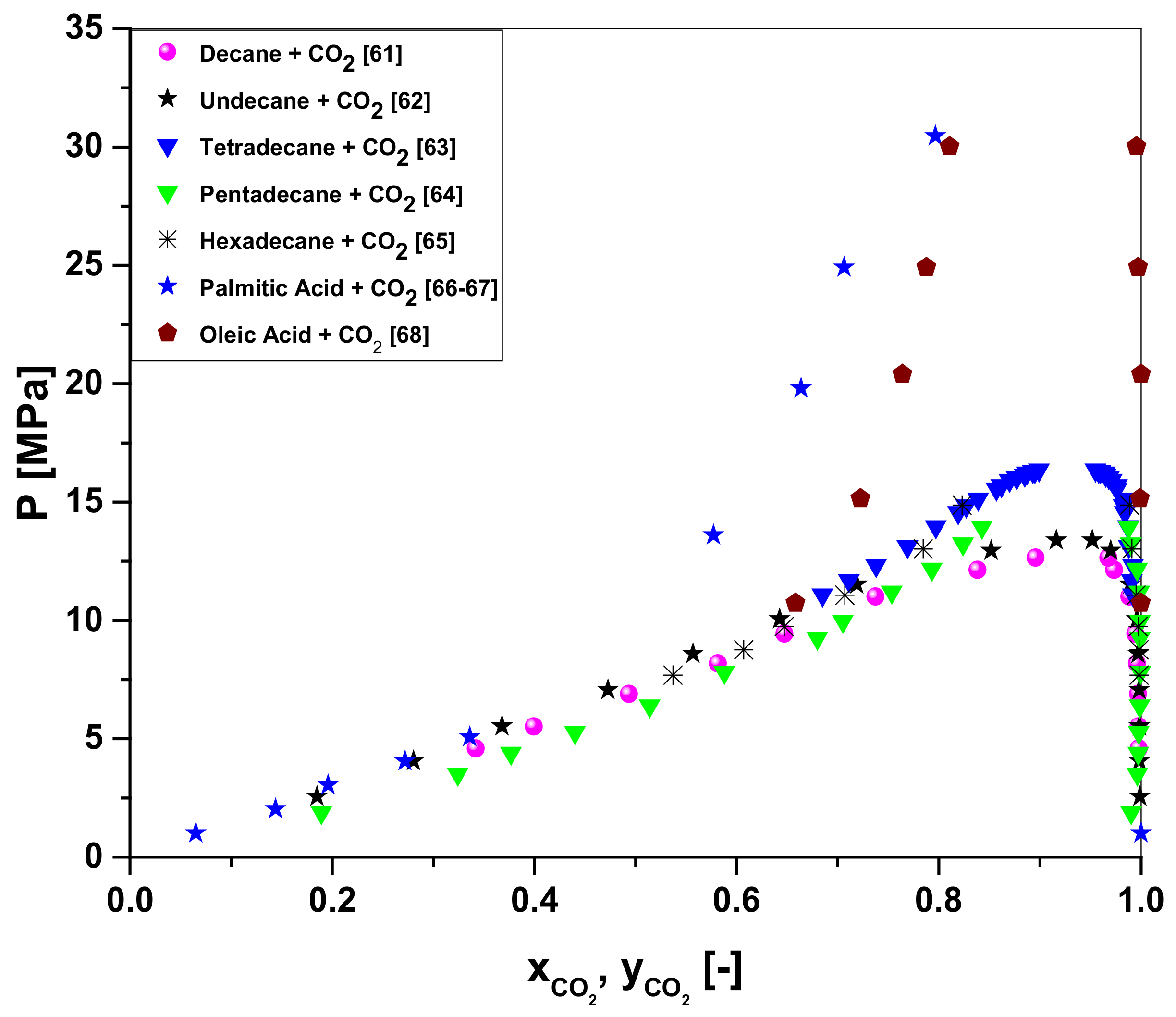
  61. Jimenez-Gallegos, R.; Galicia-Luna, L.A.; Elizalde-Solis, O. Experimental vapor-liquid equilibria for the carbon dioxide + octane and carbon dioxide + decane systems. J. Chem. Eng. Data 2006, 51, 1624–1628. [Google Scholar] [CrossRef]
  62. Camacho-Camacho, L.E.; Galicia-Luna, L.A.; Elizalde-Solis, O.; Martinez-Ramirez, Z. New isothermal vapor-liquid equilibria for the CO2 + n-nonane, and CO2 + n-undecane systems. Fluid Phase Equilibria 2007, 259, 45–50. [Google Scholar] [CrossRef]
  63. Gasem, K.A.M.; Dickson, K.B.; Dulcamara, P.B.; Nagarajan, N.; Robinson, R.L.J. Equilibrium phase compositions, phase densities, and interfacial tensions for CO2 + hydrocarbon systems, CO2 + n-Tetradecane. J. Chem. Eng. Data 1989, 32, 191–195. [Google Scholar] [CrossRef]
  64. Secuianu, C.; Feroiu, V.; Geanã, D. Phase behavior for the carbon dioxide + Npentadecane binary system. J. Chem. Eng. Data 2010, 55, 4255–4259. [Google Scholar] [CrossRef]
  65. D’Souza, R.; Patrick, J.R.; Teja, A.S. High-pressure phase equilibria in the carbon dioxide-n-hexadecane and carbon dioxide-water systems. Can. J. Chem. Eng. 1988, 66, 319. [Google Scholar] [CrossRef]
  66. Yau, J.S.; Chiang, Y.Y.; Shy, D.S.; Tsai, F.N. Solubilities of carbon dioxide in carboxylic acids under high pressures. J. Chem. Eng. Jpn. 1992, 25, 544–548. [Google Scholar] [CrossRef] [Green Version]
  67. Bharath, R.; Inomata, H.; Adschiri, T.; Arai, K. Phase equilibrium study for the separation and fractionation of fatty oil components using supercritical carbon dioxide. Fluid Phase Equilibria 1992, 81, 307–320. [Google Scholar] [CrossRef]
  68. Bharath, R.; Yamane, S.; Inomata, H.; Adschiri, T.; Arai, K. Phase Equilibria of Supercritical CO2-Fatty oil Component Binary Systems. Fluid Phase Equilibria 1993, 83, 183–192. [Google Scholar] [CrossRef]
  69. Mâncio, A.A.; da Mota, S.A.P.; Borges, L.E.P.; Machado, N.T. Obtaining of green gasoline by fractional distillation of organic liquid products from the thermal-catalytic cracking using different percentages of catalyst. Sci. Plena 2017, 13, 012711. [Google Scholar] [CrossRef] [Green Version]
Figure 1. High-pressure phase equilibrium for the binary pairs OLP-compounds-i + CO2 (decane + CO2, undecane + CO2, tetradecane + CO2, pentadecane + CO2, hexadecane + CO2, palmitic acid + CO2, and oleic acid + CO2) described in the literature [61,62,63,64,65,66,67,68].
Molecules 27 02211 g001
Figure 2. Process simulation steps using Aspen-HYSYS 8.4 for the deacidification/deoxygenation of OLP, as described elsewhere [59]: 1—the selection of the component list type; 2—the formulation of the list of components; 3—the basis formulation; 4—the flowsheet assembly of the process.
Molecules 27 02211 g002
Figure 3. Flowsheet algorithm simulation strategy for the deacidification/deoxygenation of organic liquid products, obtained through the thermal catalytic cracking of palm oil at 450 °C, 1.0 atm, with 10% (wt.) Na2CO3 as a catalyst, in multistage countercurrent absorber columns using SC-CO2 as a solvent, illustrating sub-flowsheet I with absorbers 01 and 02.
Molecules 27 02211 g003
Figure 4. Flowsheet algorithm simulation strategy for the deacidification/deoxygenation of organic liquid products, obtained through the thermal catalytic cracking of palm oil at 450 °C, 1.0 atm, with 10% (wt.) Na2CO3 as a catalyst, in multistage countercurrent absorber columns using SC-CO2 as a solvent, illustrating sub-flowsheet II with absorber 03.
Molecules 27 02211 g004
Figure 5. Process flowsheet (absorber columns (T-100, T-101, T-102), flash drums (V-100, V-100-2, V-101, V-101-2, V-102, V-103, V-104, V-105, V-106, V-107), valves (VLV-100, VLV-100-2, VLV-101, VLV-101-2, VLV-102, VLV-103, VLV-104, VLV-105, VLV-105-2, VLV-106), heat exchanges (E-100, E-100-2, E-101, E-102, E-103, E-104, E-105, E-105-2), make-ups (SET-1, SET-2), high-pressure pump (P-100)) for OLP deoxygenation in multistage countercurrent absorber columns using CO2 as a solvent (raffinate 1 + CO2 as the feed for the top stream of absorber T-102, raffinate 2 as the feed for the top stream of absorber T-101, and a CO2 make-up as the feed for the bottom stream of absorber T-102 and of absorber T-101).
Molecules 27 02211 g005
Table 1. Operating conditions of the simulation of the OLP deoxygenation process, using SC-CO2 as solvent, with the help of the chemical process simulator Aspen-HYSYS 8.6 (Aspen One, 2015).
Operating Conditions
Absorber Column 1T = 333 K
Feed = 100 kg/hp = 140 bar
Numbers of stages = 10(S/F) = 17
Absorber Column 2T = 350 K
Numbers of stages = 10p = 140 bar
Feed = Raffinate 1(S/F) = 38
Absorber Column 3T = 333 K
Numbers of stages = 10p = 140 bar
Feed = Raffinate 2(S/F) = 25
Table 2. Material and energy balances and state conditions (T, P) for all the process streams for the simulation of the OLP deoxygenation process in multistage countercurrent absorber columns using CO2 as a solvent, with Aspen-HYSYS 8.6 (Aspen One, 2015) as the simulator, expressed on a CO2 basis, at 333 K, 140 bar, and (S/F) = 17; at 350 K, 140 bar, and (S/F) = 25; and at 333 K, 140 bar, and (S/F) = 38.
Stream Nºωi,GasT
(°C)
p
(Bar)
Molar Flow
(kmol/h)
Mass Flow
(kg/h)
Liquid Vol. Flow
(m³/h)
Heat Flow
(kcal/h)
Heat Flow
(kcal/h)
PLO0601400.51961000.1214−43,708.4Q-1001361.1
CO216014038.423216912.0578−3,672,925.4Q-10119,905.9
11147.9414020.0574910.05841.1081−1,872,017.7Q-102763.3
20.9252277.7814018.8854880.94161.0712−1,794,358.8Q-100-280.7
5193.5414049.89522227.4742.7105−4,718,556.9Q-103154.0
60.9301798.151405.1121243.1860.2952−483,682.8Q-104318.3
CO2#2177.7814036.12191589.7181.9346−3,431,362.5Q-1062496.4
3121.644049.19592165.2392.6349−4,652,389.5Q-106-21843.5
4021.64400.699362.23497.56 × 10−3−66,167.4Q-105214.0
5-20.9859821.644049.89522227.4742.7105−4,718,556.9
6-20.66532−37.001.50.699362.23497.56 × 10−2−66,167.4
70.69432251.50.699362.23497.56 × 10−2−64,806.3
81251.50.485521.37672.60 × 10−2−45,671.2
90251.50.21376740.85814.95 × 10−2−19,135.1
100.98826107.404520.0574910.05841.1081−1,872,017.7
111354519.4630856.9091.0428−1,838,423.0
12035450.594353.14946.53 × 10−2−53,500.6
130.62478−14.021.50.594353.14946.53 × 10−2−53,500.6
141251.50.379416.71902.03 × 10−2−35,684.9
150251.50.214936.43044.49 × 10−2−17,052.4
170.97036354520.0574910.05841.1081−1,891,923.6
180.63841251.50.594353.14946.53 × 10−2−52,737.3
3-2146.09504.8689214.29470.2607−459,529.9
4-2046.09500.243228.89133.45 × 10−2−24,152.8
5-30.9524246.09505.1121243.1860.2952−483,682.8
6-30.5760218.041.50.243228.89133.45 × 10−2−24,152.8
7-20.57774251.50.243228.89133.45 × 10−2−24,072.1
8-21251.50.14056.18407.53 × 10−3−13,217.3
9-20251.50.102622.70732.70 × 10−2−10,854.8
16030.121400.102622.70732.70 × 10−2−10,700.7
190601400.102622.70732.70 × 10−2−10,382.4
201601406.1480270.57423.29 × 10−1−587,699.0
21172.811404.1244185.10772.25 × 10−1−392,745.7
220.9908060.391402.1263108.17380.1310−204,486.5
230.5105725.12602.1263108.17380.1310−204,486.5
25125.12601.08547.78245.81 × 10−2−103,080.1
291251.50.958942.20255.14 × 10−2−90,200.8
300251.58.18 × 10−218.18882.16 × 10−2−8709.2
270.68209−82.521.51.040660.39137.29 × 10−2−101,406.4
280.92143251.51.040660.39137.29 × 10−2−98,910.0
26025.12601.040660.39137.29 × 10−2−101,406.4
27-20.8404315.85504.1244185.10772.25 × 10−1−392,745.7
28-20.9752125504.1244185.10772.25 × 10−1−390,902.2
24125504.0221177.02082.15 × 10−1−380,896.7
31025500.10228.08699.73 × 10−3−10,005.5
320.79566251.50.10228.08699.73 × 10−3−9791.4
341251.58.13 × 10−23.57964.36 × 10−3−7650.9
350251.52.09 × 10−24.50725.37 × 10−3−2140.5
330.74861−54.911.50.10228.08699.73 × 10−3−10,005.5
Table 3. Chemical composition, expressed on a solvent-free basis, of hydrocarbons and oxygenates of OLP in feed, top, and bottom streams of absorber columns T-100, T-102, and T-101 following the simulation of the OLP deoxygenation process in multistage countercurrent absorber columns using CO2 as a solvent, with Aspen-HYSYS 8.6 (Aspen One, 2015) as the simulator, expressed on a CO2 basis, at 333 K, 140 bar, and (S/F) = 17; at 350 K, 140 bar, and (S/F) = 25; and at 333 K, 140 bar, and (S/F) = 38.
FeedColumn 1Column 2Column 3
(S/F)-173825
OLPTopBottom
(RAF1)
TopBottom
(RAF2)
TopBottom
Mass Flow (kg/h)10036.6563.3540.7722.584.0718.49
Mass fraction (CO2-free basis)
Hydrocarbons0.89240.96950.84780.92780.70340.83850.6734
Alkanes0.41930.39140.43540.46530.38150.43210.3701
Alkenes0.25340.36390.18950.21750.13880.13890.1389
Naphthenes0.21970.21420.22290.24490.18310.26740.1644
Oxygenates0.10760.03050.15220.07220.29660.16150.3266
Carboxylic acids0.02630.00520.03850.01470.08140.03540.0916
Alcohols0.03510.00860.05050.01740.11020.04120.1255
Ketones0.04620.01670.06320.04020.10490.08490.1094
Publisher’s Note: MDPI stays neutral with regard to jurisdictional claims in published maps and institutional affiliations.

