Article

Mineral Assemblages, Textures and In Situ Sulphur Isotope Geochemistry of Sulphide Mineralization from the Cyprus-Type Ice Volcanogenic Massive Sulphide (VMS) Deposit, Yukon, Canada

1
Iron Ore Company of Canada, 2 Avalon Drive, Labrador City, NL A2V 2Y6, Canada
2
Department of Earth Sciences, Memorial University of Newfoundland, 9 Arctic Ave, St. John’s, NL A1B 3X5, Canada
3
63 Bellingham Court, Whitehorse, YT Y1A 0N2, Canada
4
CREAIT Network, Room IIC1001, Bruneau Centre for Research and Innovation, Memorial University of Newfoundland, St. John’s, NL A1C 5S7, Canada
*
Author to whom correspondence should be addressed.
Minerals 2018, 8(11), 501; https://doi.org/10.3390/min8110501
Submission received: 2 October 2018 / Revised: 26 October 2018 / Accepted: 29 October 2018 / Published: 1 November 2018
(This article belongs to the Special Issue Massive Sulfide Deposits all around the World)

Abstract

:
The Permian (~273–274 Ma) Ice volcanogenic massive sulphide (VMS) deposit represents a mound shaped Cyprus (mafic)-type VMS deposit (~4.5 Mt @ 1.5% Cu) hosted in basaltic rocks of Slide Mountain terrane. The deposit consists of massive sulphides that are underlain by a chlorite-sulphide-hematite-rich stringer pipe, and overlain by a hematite-(pyrite)-rich exhalative chert. The sulphides are divided into five facies: (1) pyrite-rich; (2) pyrite-bornite-rich; (3) pyrite-chalcopyrite-rich; (4) hematite-pyrite; and (5) stringer sulphide. The sulphides have a distinct paragenetic and textural evolution in the massive sulphide that reflect: (1) an early, low temperature stage (<250 °C dominated by Fe-Zn-Cu-rich mineralization; (2) an intermediate, high temperature stage (>300 °C) dominated by Cu-Fe-rich mineralization; and (3) a late, low temperature phase (<150 °C) dominated by Fe-rich mineralization. In situ sulphur isotope data pyrite and chalcopyrite (by secondary ion mass spectrometry (SIMS)) range from δ34S = +1.8‰ to +8.2‰, but vary as a function of paragenesis and temperature of deposition. Both early and late forming sulfides were dominated by sulphur from partial thermochemical sulphate reduction (TSR) of seawater sulfate, whereas intermediate, high temperature mineralization was dominated leached, igneous sulphur from basement rocks. These results are similar to modern seafloor vents and many ancient VMS deposits.

1. Introduction

Cyprus-type (also known as mafic-type) volcanogenic massive sulphide (VMS) deposits have been historically important contributors to global metal production [1,2], and are the focus of mineral exploration in certain jurisdictions (e.g., Newfoundland Appalachians and Scandinavian Caledonides). These deposits are hosted in basaltic sequences, commonly ophiolites (e.g., References [1,3]), and are considered ancient analogues to modern basalt-hosted VMS deposits [1,4,5]. Despite their historical and ongoing exploration importance, they have received little research attention in recent years, and only a few have been documented in North America, with most literature from the 1970s and 1980s [6,7,8]. Furthermore, very little S isotopic data exists for Cyprus-type deposits and most older S isotope data are from bulk (conventional) methods [7,8], with little in situ, paragenetically controlled data. As a result, most existing sulphur isotope data do not show variations as a function of the temporal and mineralogical evolution of the deposits.
In this paper we provide a detailed sulphide mineral, textural, and in situ secondary ion mass spectrometry (SIMS) study of sulphide mineralization from the Ice VMS deposit, southeast Yukon, Canada. This deposit provides a unique opportunity to study a relatively pristine, Cyprus-type VMS deposit. In this paper we will utilize field geology, transmitted and reflected light microscopy, scanning electron microscopy, and SIMS sulphur isotope data to: (1) document the mineralogy, mineral assemblages, textures, and paragenetic evolution of sulphide minerals in the Ice deposit; (2) determine the sulphur source(s) and evolution of sulphur isotopic compositions in sulphide minerals as a function of paragenesis; and link (1) and (2) to provide a model for the mineralogical, textural, and hydrothermal evolution of the Ice VMS deposit. These results will have implications for the origin of ancient Cyprus-type VMS deposits and also provide insight into broader VMS deposit genesis and sulphur sourcing in VMS systems.

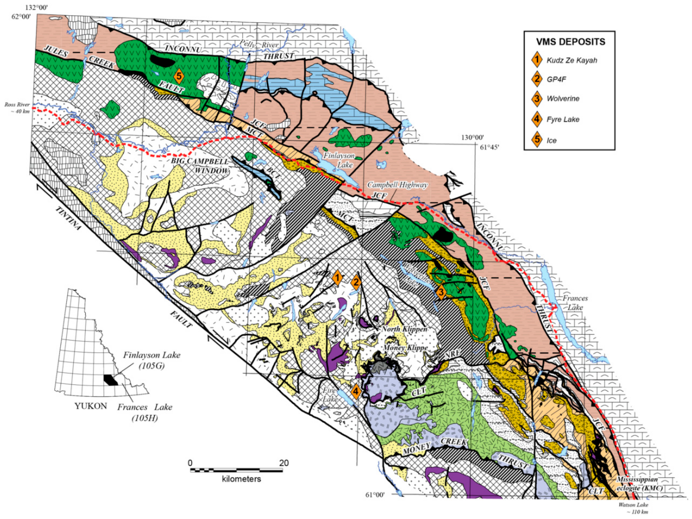
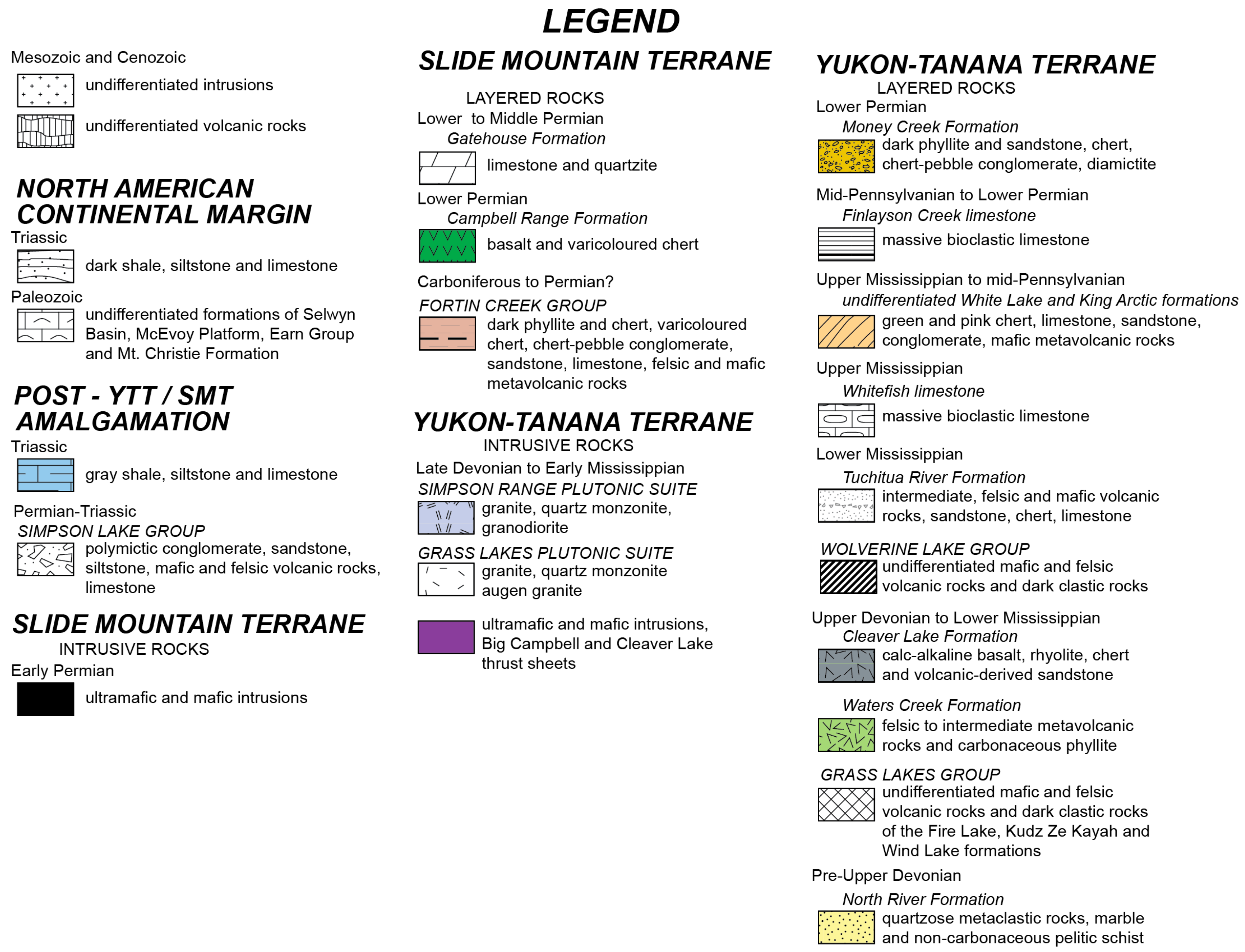
2. Regional Geology and Tectonic Setting

The Ice VMS deposit is located within the Finlayson Lake VMS district in Southwestern Yukon (Figure 1) [9,10]. The Finlayson Lake district consists of a number of thrust-bounded panels hosting VMS mineralization that ranges in age from ~365 to 275 Ma, and varies in style from mafic siliciclastic (Besshi-type—~365 Ma Fyre Lake), to bimodal felsic (Kuroko-type—~360 Ma Kudz ze Kayah, Krakatoa, GP4F), to felsic siliciclastic (Bathurst-type—~347–345 Ma Wolverine), to mafic (Cyprus-type—~273–274 Ma Ice) [9,10]. The various panels are interpreted to represent a telescoped arc to back-arc system that formed along the distal edge of the North American craton, with deposits forming within arc rifts and back-arc basins [9,10,11,12,13]. However, within each thrust panel there are stratigraphically intact sequences that show consistent stratigraphic order and upward younging of units, arguing that most mapped contacts within thrust blocks are stratigraphic [9].
The Ice deposit is hosted within rocks of the Slide Mountain terrane that lie in fault contact with rocks of the North American cratonic margin along the Inconnu thrust (Figure 1 and Figure 2). Despite localized faulting, most contacts are stratigraphic, and the rocks are very well preserved with abundant primary mineralogical and textural relationships and only a minor subgreenschist-greenschist (Cretaceous aged?) facies metamorphic overprint [14]. The Campbell Range rocks lie in stratigraphic contact with underlying rocks of the Yukon-Tanana terrane, but are offset in places along the Jules Creek fault (Figure 1) [9,11]. The Slide Mountain terrane in the Finlayson Lake region consists of two assemblages: the Fortin Creek group and Campbell Range formation (Figure 1 and Figure 2) [9,10]. The Fortin Creek group is composed of calcareous sedimentary rocks and is overlain by ophiolite-like rocks of the Campbell Range formation (Figure 1 and Figure 2) [9,10]. The Campbell Range formation consists of basaltic rocks with lesser chert, conglomerate, high level mafic intrusive rocks, and carbonates, and is intruded by synvolcanic gabbroic intrusive rocks (Figure 1 and Figure 2) [9,10]. The age of the Campbell Range formation is constrained by both fossil ages to be Permian (Harms in [14]) and by U-Pb radiometric ages [9,15] for subvolcanic gabbroic rocks in the area, which range from 273.4 ± 1.4 to 274.3 ± 0.5 Ma. The rocks of the Ice deposit have similar chemistry to the dated gabbroic rocks [11], and are stratigraphically similar to the Campbell Range formation rocks that contain Permian radiolarians (Harms in [14]); thus, it is reasonable to assume that the rocks at the Ice deposit are ~273–274 Ma.

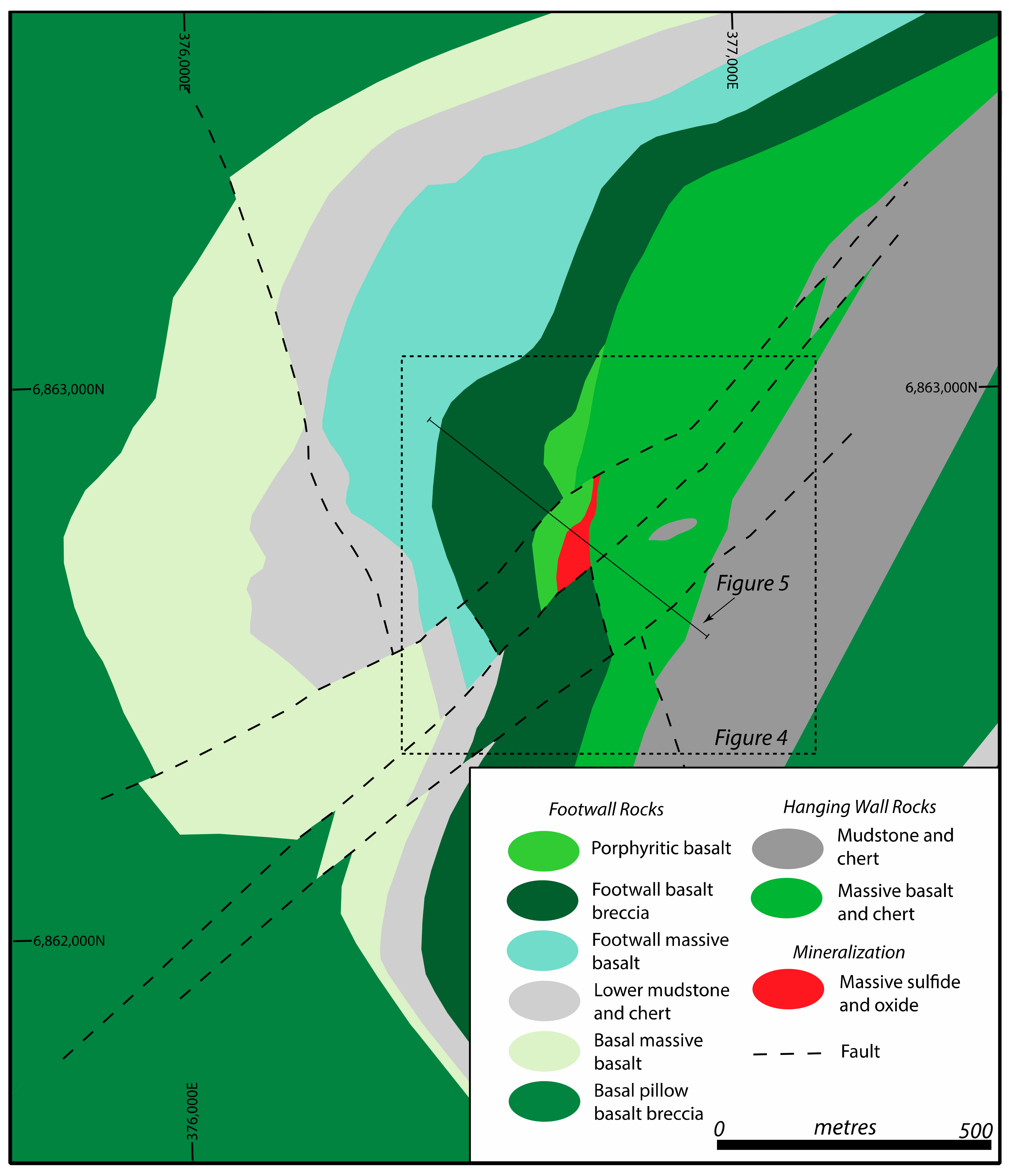
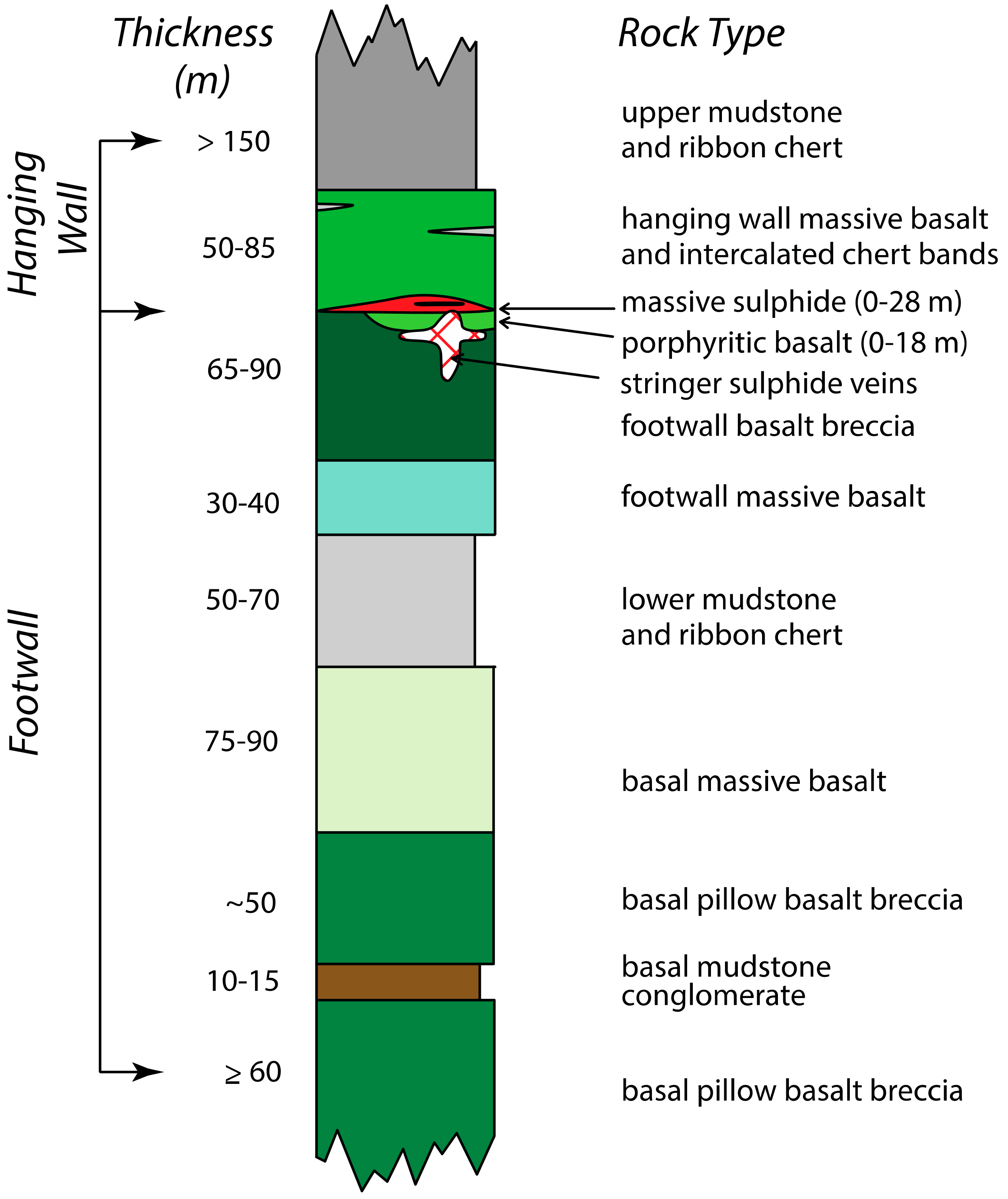
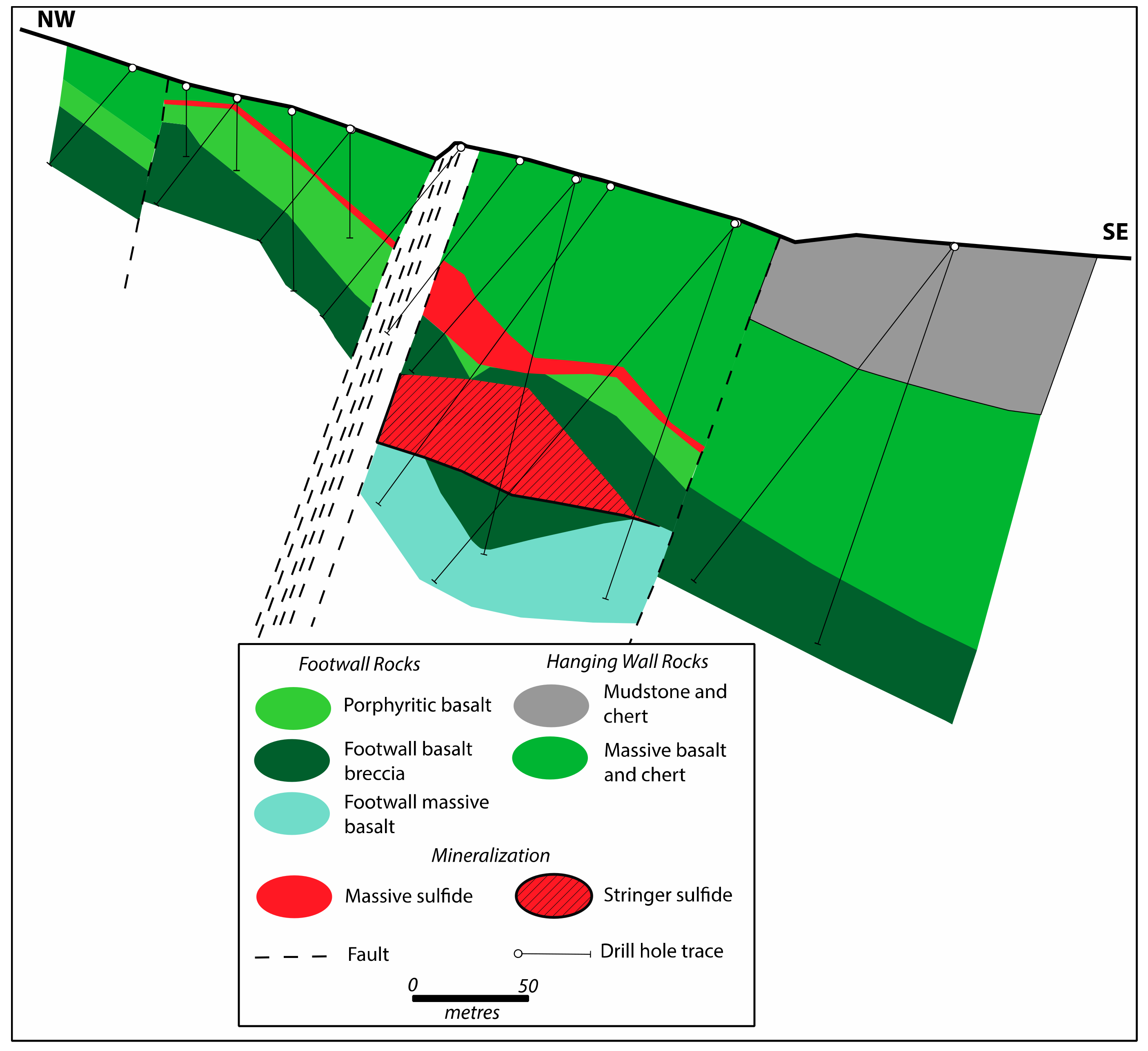
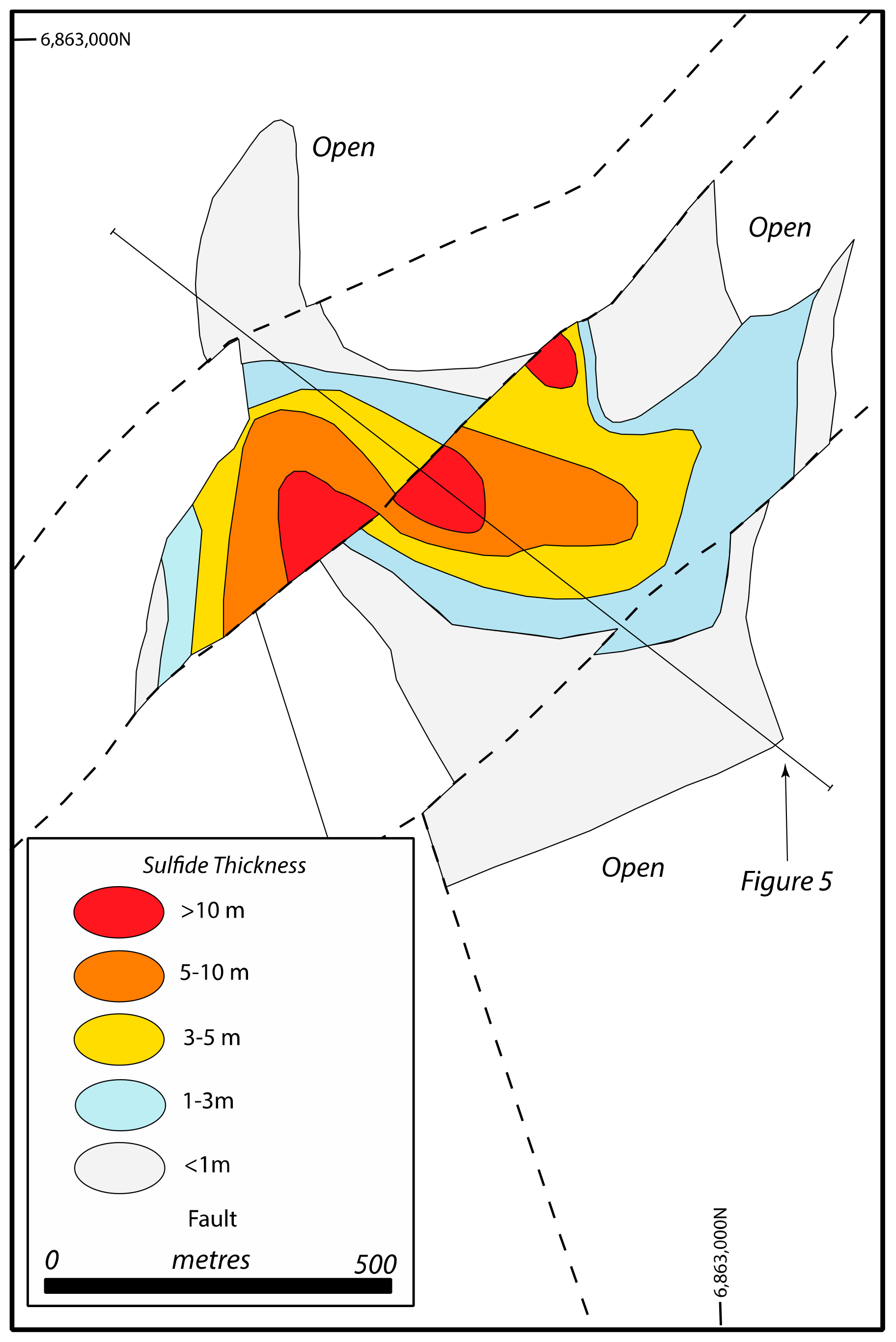
3. Geology of the Ice Deposit

The Ice deposit is hosted entirely in Permian Campbell Range formation basalt, chert and lesser sedimentary rocks, which dip towards the southeast (Figure 1, Figure 2 and Figure 3) [10,16,17,18]. The basalts include porphyritic pillowed flows, autobrecciated pillowed flows, and massive basalt (Figure 3, Figure 4 and Figure 5) [10,16,17,18]. These lithologies are interbedded with ribbon chert of variable color, and sedimentary rocks, including greywacke and carbonaceous mudstone (Figure 3, Figure 4 and Figure 5) [10,16,17,18]. The entire stratigraphic sequence consists of a series of flows that are indistinguishable except for a plagioclase porphyritic flow that lies in the immediate footwall to the deposit (Figure 3, Figure 4 and Figure 5) [10,16,17,18]. Outside of the immediate deposit area the rocks have very low grade metamorphism (sub-greenschist to greenschist), similar to regional metamorphism throughout the Campbell Range [14].
The massive sulphide body has been defined along a strike of approximately 1000 m and has an historic resource (i.e., not NI-43-101 compliant) of ~4.5 million tonnes at 1.5% Cu, with local enrichments Zn, Au, Ag and Co [16,17]. The massive sulphide lens has an average thickness of ~5 m and a 15–16 m thick core (Figure 6) [10]. The core of the deposit is Cu-rich, consisting predominantly of chalcopyrite, bornite, and sphalerite (e.g., Figure 7 and Figure 8) [10,16,17,18]. Copper grades decrease toward the thinner, outer extents of the deposit, whereas Zn is generally found proximal to the thickest part of the deposit [10,16,17,18].
The immediate footwall to the deposit consists of a porphyritic basalt that ranges in color from medium green to dark grey-green with an aphanitic groundmass and plagioclase phenocrysts (Figure 3, Figure 4 and Figure 5) [10,16,17,18]. The porphyritic basalt is underlain by brecciated basalt (footwall basalt breccia; Figure 3, Figure 4 and Figure 5) that is a predominantly hyaloclastite-rich unit associated with pillowed basalt flows [10,16,17,19]. Both of these units contain abundant pyrite-quartz-chalcopyrite-specular hematite stringer veins (Figure 3, Figure 4, Figure 6 and Figure 7) [10,16,17,19]. In some cases, the porphyritic basalt is absent and the massive sulphide lens lies directly on the footwall breccia basalt [10,16,17,19].
The deposit hanging wall consists of a massive basalt that is medium grained, medium to dark green, equigranular, and homogenous (Figure 3, Figure 4 and Figure 5) [10,16,17,19]. Thin, varicolored chert bands are interbedded with the hanging wall basalt (Figure 3, Figure 4 and Figure 5) [10,16,17,19]. Between the massive basalt and the massive sulphide lens is a 5–50 centimetre siliceous, hematitic chert horizon [10,16,17,19].
Relict plagioclase laths and interstitial clinopyroxene crystals are present in some of the basalt; however, the rocks have reached subgreenschist to greenschist facies metamorphism, and most of the primary mineralogy has been altered [17]. The metamorphic assemblages include fine-grained clinozoisite, epidote, chlorite, sericite, quartz, and actinolite [17].

4. Mineralization

The mineralization in the Ice deposit is dominated by pyrite forming a mound underlain by a chloritic stringer zone with pyrite, hematite, and chalcopyrite (Figure 3, Figure 5 and Figure 6). The deposit also contains chalcopyrite, bornite, and sphalerite (Figure 7 and Figure 8). Bornite, sphalerite, and chalcopyrite are enriched in the massive sulphides proximal to the stringer sulphide zone; this is also where the Cu-Zn grades are highest [17]. The relative abundances of bornite and chalcopyrite vary leading to chalcopyrite-rich and bornite-rich sulphides, respectively, if either phase comprises >20% of the sulphides. The pyrite-rich sulphides grade stratigraphically upwards and outwards from the thickest massive sulphide intersections into hematitic chert (chert-rich sulphides) that is variably pyritic and is interpreted to represent an exhalite (Figure 5, Figure 7 and Figure 8) [10]. The sulphide zone is underlain by pyrite-hematite-chalcopyrite-chlorite-rich mineralization (stringer sulphides) that is interpreted to represent the feeder pipe to mineralization (Figure 5, Figure 7 and Figure 8) [10]. Given the low metamorphic grade and preservation of delicate textures in the sulfides that are similar to modern hydrothermal vents, we assume that the textures found within the mineralization at Ice are primary, as are any geochemical or isotopic signatures recorded in these phases (see Section 4.1, Section 4.2 and Section 5 below).

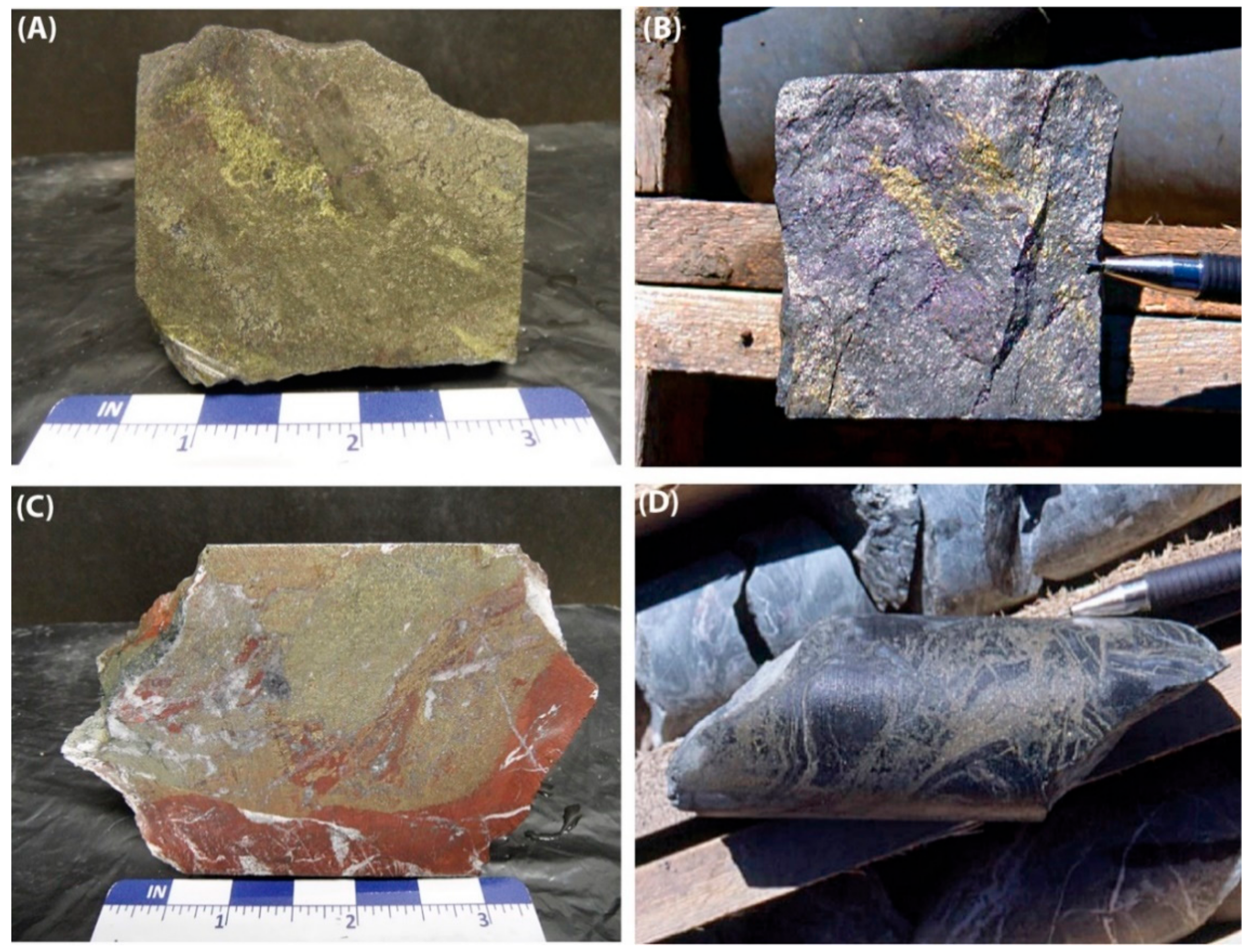
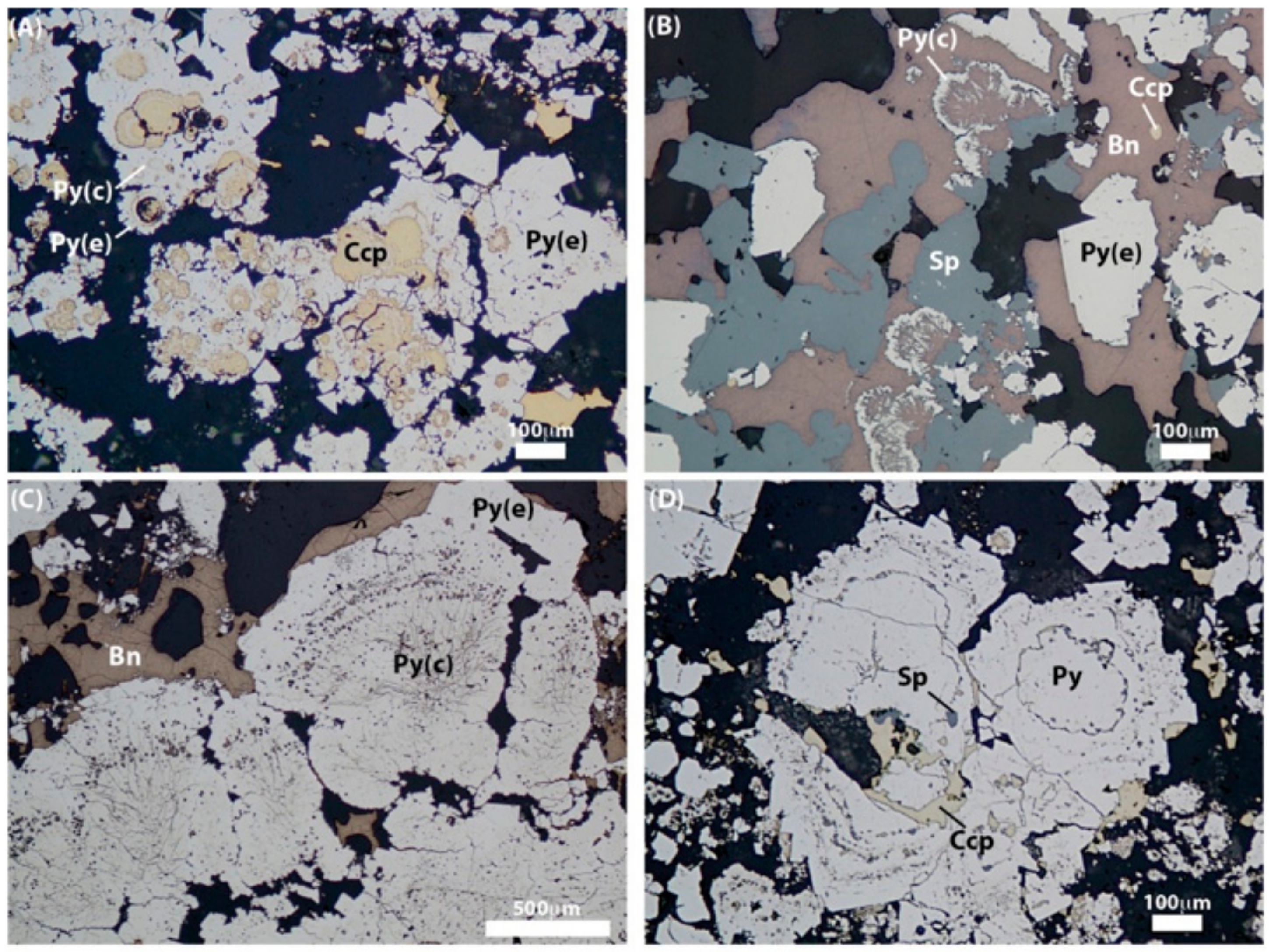
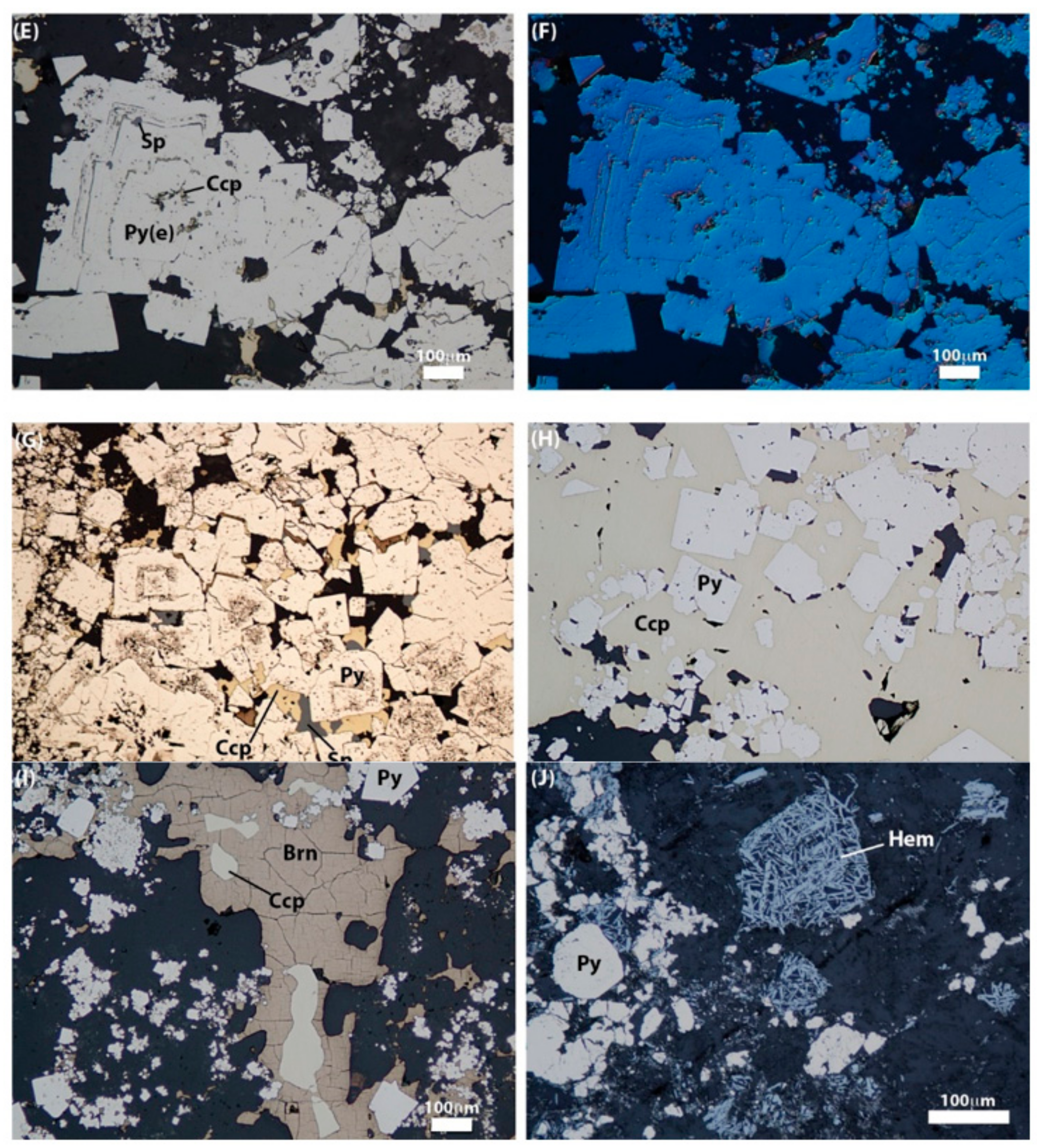
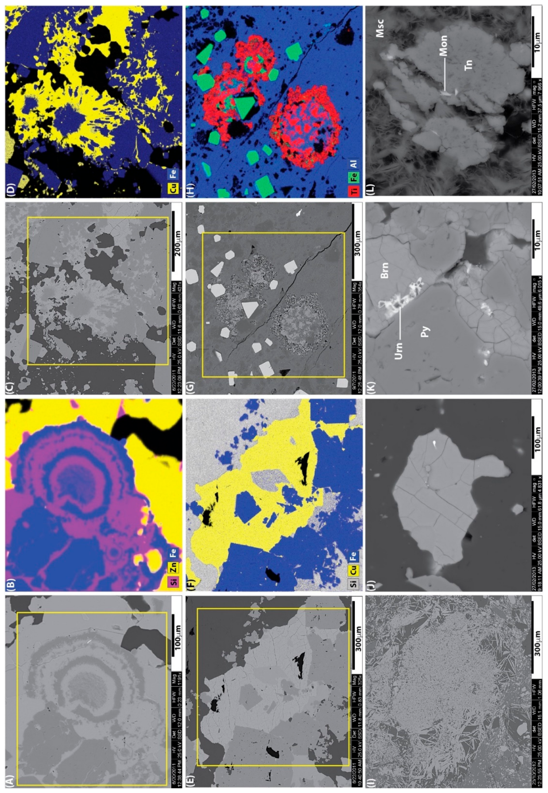
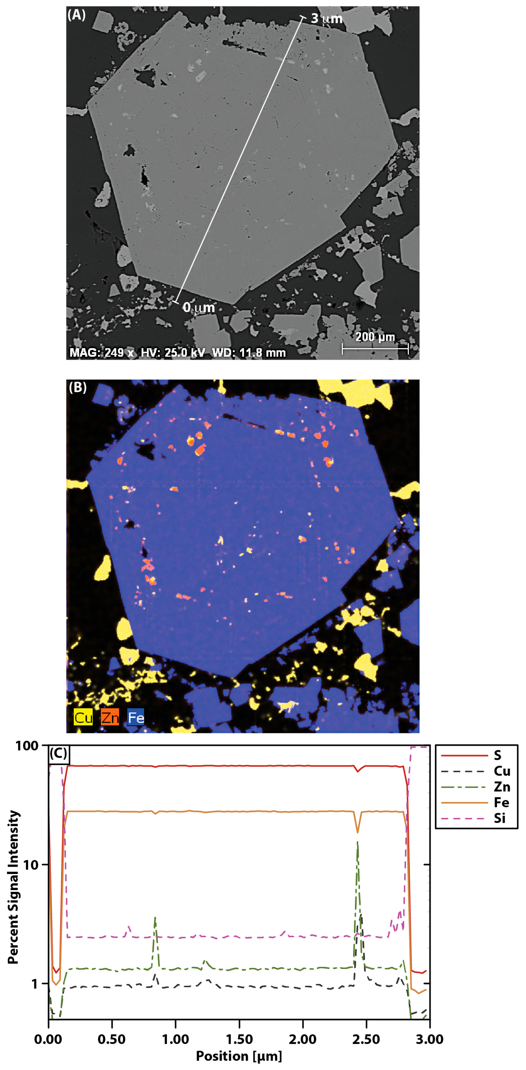
4.1. Ore Mineralogy and Textures
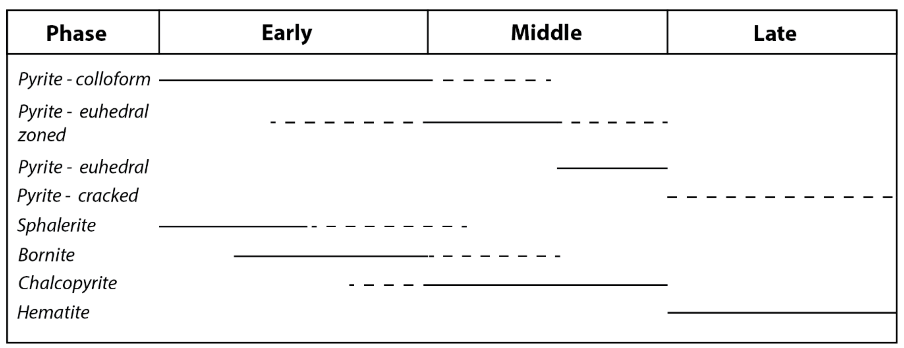
Representative polished thin sections of the mineralization were studied for their sulphide/oxide mineralogy, mineral assemblages, and paragenesis using a combination of transmitted and reflected light, including differential interference contrast (DIC) imaging (i.e., Nomarski interference imaging; [20]) in the Department of Earth Sciences, Memorial University of Newfoundland. Scanning electron microscopy was utilized for understanding mineral assemblages, textural relationships, and mineral parageneses not easily visible using standard microscopic methods. In addition, the SEM was also utilized for obtaining mineral spectra, and semi-quantitative elemental maps and line scans of various phases and assemblages. The SEM work was completed at the Bruneau Innovation Centre at Memorial University of Newfoundland using a FEI QUANTA 650 field emission gun (FEG) ultra-fast SEM equipped with a Bruker energy dispersive spectrometer (EDS) with a silicon drift detector. Operating conditions for SEM included an accelerating voltage of 25 kV and a beam current of 10 nA. Semi-quantitative energy dispersive X-ray element maps and line scans for samples were collected and processed using Bruker Espirit 1.9 Microanalysis Software (Bruker, Billerica, MA, USA). The sample suite was dominated by the massive sulphide samples with only a few representative samples from the exhalative unit and the stringer sulphides. Correspondingly, most relationships presented herein are focused on those found in the massive sulphides.
The Ice samples are dominated by varying amounts of pyrite, chalcopyrite, and bornite, with minor sphalerite (Figure 7, Figure 8, Figure 9 and Figure 10). The dominant sulphide mineral in all samples is pyrite, regardless of sulphide facies. Bornite and chalcopyrite are enriched in chalcopyrite-rich to bornite-rich sulphides, but also occur in lesser abundance in pyrite-rich and chert-bearing sulphides. Chalcopyrite is more common than bornite in stringer sulphides. Hematite is also present in significant amounts in the stringer- and chert-rich sulphides.
Pyrite displays a wide variety of textures. It often forms delicate, colloform layers that are in pyrite-, chalcopyrite-, and bornite-rich facies (Figure 8A–D and Figure 9A,B). The colloform grains exhibit complex intergrowths with chalcopyrite and bornite (Figure 8A–D and Figure 9A–D ), whereas in other cases they are partly to fully replaced by chalcopyrite and bornite forming atoll textures with resorbed pyrite surfaces (Figure 8A–D and Figure 9A–D ). These colloform grains grade into more zoned pyrite grains that contain relict colloform cores that grade outwards into subhedral to euhedral pyrite rims, often with well-developed zoning (Figure 8E–G). Pyrite grains are also frequently zoned with growth patterns marked with inclusions of chalcopyrite, bornite, and sphalerite (Figure 8E–G and Figure 10). In the stringer sulphides and more chalcopyrite-rich materials, there are also very well developed, unzoned, euhedral pyrite that are commonly inclusion-free (Figure 8H). In some other cases, large pyrite grains are heavily fractured, or occur within the gangue of basalt in stringer-type sulphides (Figure 8J). The pyrite grains have a distinct paragenesis from early colloform, to colloform to partly recrystallized and zoned, to euhedral zoned, to euhedral unzoned, to fractured grains (Figure 11).
Chalcopyrite and bornite are the next most common sulphide minerals with their relative abundances varying between samples: Stringer sulphide samples are dominated by pyrite and chalcopyrite (with hematite), whereas some massive sulphide samples are richer in bornite (with chalcopyrite and sphalerite) (Figure 8 and Figure 9). Chalcopyrite displays a variety of textures. It most commonly occurs as anhedral masses, interstitial to pyrite, partially resorbed into pyrite, along pyrite growth zones in both colloform, and euhedral pyrite, at the center of some pyrite atolls, and along cracks in pyrite grains (Figure 8A,E–G and Figure 9A–F ). Texturally, bornite is very similar to chalcopyrite, occurring as anhedral crystals interstitial to pyrite and in cracks in pyrite grains (Figure 8B,C,I and Figure 9C–F ). In other cases, bornite alternates with pyrite in colloform grains resulting in alternating rings of pyrite and bornite along growth zones of euhedral pyrite. In other cases, it occurs as small inclusions along growth zoning, and occurs in central void spaces and along the edges of pyrite atolls (Figure 8B and Figure 9C,D). Chalcopyrite and bornite display intimate intergrowth textures sometimes within single cracks in pyrite grains (Figure 8G,I and Figure 9C–F ).
Sphalerite is present in minor amounts in most samples. It is texturally like chalcopyrite and bornite occurring: (1) as anhedral grains commonly interstitial to pyrite; (2) within atoll resorption textures with pyrite; (3) as intergrowths with bornite and chalcopyrite; and (4) as anhedral blebs within bornite, pyrite, and chalcopyrite (Figure 8B–G, Figure 9A,B and Figure 10).
Hematite is a common feature of the stringer sulphides beneath the massive sulphides. In the stringer sulphides hematite occurs as elongate, needle-like crystals that are disseminated throughout the basalt; they also occur as large clusters partially to completely replacing pyrite in massive sulfides (Figure 8J and Figure 9I). Hematite also occurs in the chert above mineralization that is interlayered with pyrite where it occurs as anhedral and massive clots closely associated with pyrite.
There are several trace minerals present in the Ice samples, including minor anhedral uraninite within bornite grains in bornite-rich massive sulphide (Figure 9K), and Se-rich galena occurs in the chalcopyrite and pyrite stringer facies (Figure 9J). Monazite-(Ce) and titanite are also intergrown within the basaltic rocks in the stringer facies sulphides (Figure 9G,H,L).

4.2. Paragenesis

The paragenesis of the main ore mineral phases is shown in Figure 11. Pyrite shows the greatest textural variability from early colloform pyrite, to successively more euhedral and inclusion-free pyrite. Sphalerite, and to a lesser extent bornite, is associated with the colloform pyrite and within zoned pyrite. The shift from colloform to euhedral pyrite corresponds to an increase in the chalcopyrite content of the mineral assemblage; euhedral, inclusion-free pyrite is almost exclusively found within chalcopyrite-pyrite-dominated assemblages. Hematite is associated with the latest stage of hydrothermal activity and is found within both the host rocks and stringer sulphides in the footwall, and overprints all other phases, partially to fully replacing pyrite and chalcopyrite in the massive sulphides. Cracked pyrite is a late stage feature and is possibly due to localized post-VMS deformation.

5. Sulphur Isotope Geochemistry

5.1. Analytical Methods
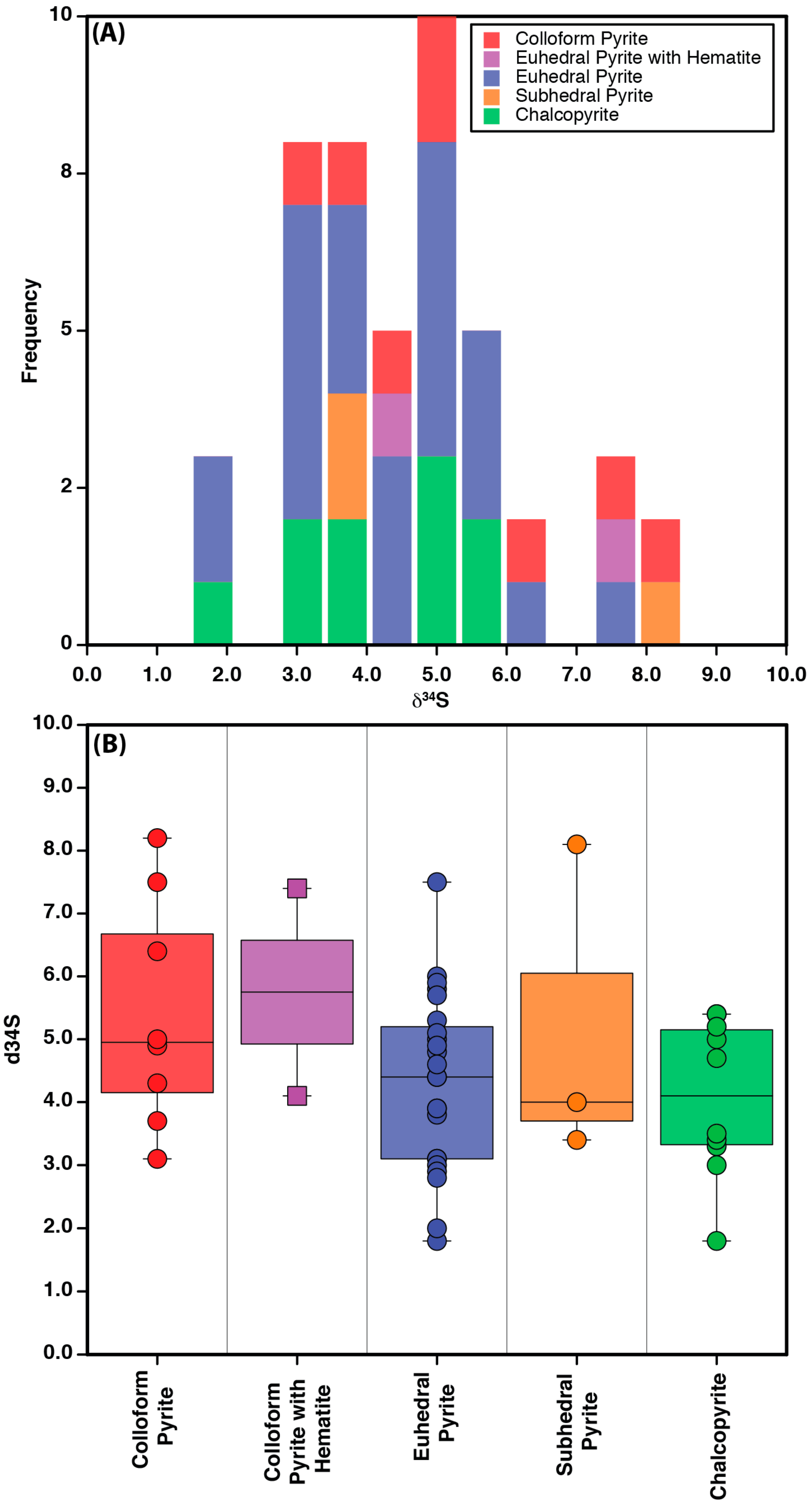
Potential grains of interest were chosen from thin sections and the off cuts of the sections were prepared as 25 mm polished mounts. Mineral maps and minerals of interest were imaged, coated with Au and then analyzed using a Cameca IMS 4f secondary ion mass spectrometery (SIMS) (Cameca, Paris, France) Bruneau Innovation Centre at Memorial University of Newfoundland using the methods detailed in Brueckner et al. [21] and summarized below. Sulphur isotope ratios were determined bombarding the sample with a primary ion microbeam of 600–850 pA of Cs+, accelerated through a 10 keV potential, and focused into a 5–15 µm diameter spot. To exclude exotic material in the polished surface from analysis, each spot was first pre-sputtered for 180 s with a 25 µm square raster applied to the beam. Negatively charged sputtered secondary ions were accelerated into the mass spectrometer of the instrument through a potential of 4.5 keV. Each individual analysis was accumulated in roughly 12 min and routinely yields internal precisions on individual δ34S determinations of better than ±0.2‰ (1σ), while producing sputter craters only a few µm deep. These precisions closely approach the optimum possible precision as calculated from Poisson counting statistics. Overall reproducibility, based on replicate standard analyses, is typically better than ±0.5‰ (1σ).

5.2. Results

The δ34S values of chalcopyrite and pyrite collected from the six Ice deposit samples are reported in Table 1 and Figure 12. Pyrite grains that are colloform are considered to have formed paragenetically early, euhedral pyrite are formed during the middle paragenetic stage, and pyrite associated with hematite are considered paragenetically late; chalcopyrite is interpreted to have formed during the middle stage of paragenesis.
δ34S values measured in the Ice deposit samples range from +1.8‰ to +8.2‰ (average = +4.6‰). The δ34S values for chalcopyrite range from 1.8‰ to 5.4‰ (average = 4.1‰). Pyrite grains have δ34S values that range from 1.8‰ to 8.2‰ (average = 4.7‰), but vary as a function of texture and paragenesis with colloform grains having higher δ34S values relative to euhedral grains (Figure 12), suggesting that the sulphides became isotopically lighter later in the paragenesis of the deposit. The higher δ34S values in pyrite (i.e., >7.0‰), regardless of textural type, are common to those associated with bornite or hematite (Table 1).

6. Discussion

6.1. Mineralogical and Ore Textural Evolution

The Ice deposit is an example Cyprus (mafic)-type VMS deposit with a stringer sulphide stockwork overlain by a mound shaped massive sulphide lens [1,22] (Figure 3, Figure 4, Figure 5 and Figure 6). The two main styles of mineralization in the Ice deposit are: (1) pyrite-chalcopyrite stringer sulphides hosted in a brecciated pillow basalt; and (2) semi-massive to pyritic massive sulphides that are variably chalcopyrite- to bornite-rich and dominated by varying amounts of pyrite, chalcopyrite, and bornite, with minor sphalerite (Figure 6, Figure 7, Figure 8 and Figure 9).
Textural evidence suggests that the first sulphide minerals to form in the Ice deposit were colloform pyrite and sphalerite (±bornite and galena) (Figure 10). The delicately textured colloform pyrite, along with sphalerite and galena, indicate they were deposited from low fluid temperature fluids (~200–300 °C) [22,23,24] early in the paragenetic history of the deposit. The colloform pyrite are inferred to have been deposited due fluid supersaturation, which resulted in in high rates of pyrite nucleation and crystallization [25,26].
The relationships between the colloform pyrite and euhedral pyrite, chalcopyrite, and bornite all suggest that the temperatures continued to increase from <300 °C (early paragenetic stage) to ~300–350 °C (middle paragenetic stage) as the deposit evolved and matured (e.g., References [22,23,24,27]). The temperature increase is indicated by the introduction of a Cu-rich mineral assemblage, which requires fluid temperatures >300 °C [22,23,24,28], and by the coarsening and recrystallization of colloform pyrite grains (Figure 8). In particular, the large, euhedral pyrite sheets that formed during the middle paragenetic stage are interpreted to have originally been colloform but subsequently recrystallized, as relict colloform textures exist inside some of the euhedral sheets (Figure 7). This process of pyrite recrystallization in interpreted to record the increase in fluid temperatures and a textural ripening of the mound/vent [4,27], reflected in progressive changes in pyrite texture from fine-grained delicate colloforms (early), to colloforms with more coarse-grained outer edges (early to middle), to large subhedral grains (middle), and finally large, perfectly euhedral sheets (middle) (Figure 8, Figure 9 and Figure 11). The formation of more euhedral and coarse pyrite (middle paragenetic stage) is associated with chalcopyrite and bornite, and this is exemplified by the presence of these phases having corrosion textures along the edges of colloform pyrite, as well new growth zones of pyrite intergrown with chalcopyrite (Figure 8 and Figure 9). This indicates that the high temperature Cu-rich fluids were present during and after the recrystallization and growth zoning of the pyrite grains from the middle paragenetic stage (Figure 11). Minor sphalerite is also present along some pyrite growth zones (Figure 10) in the middle paragenetic stage, which indicates that at least some sphalerite was still being deposited during episodes of Cu-rich, higher temperature fluid discharge (Figure 11). This is further confirmed by the fact that sphalerite displays intergrowths with chalcopyrite where the two minerals appear to be in local equilibrium.
Another effect of the increase in temperature is the partial resorption of pyrite during the middle paragenetic stage of deposit formation. Pyrite often displays resorption textures with partial replacement of colloform pyrite grains by chalcopyrite, bornite, and rarely sphalerite (Figure 8 and Figure 9). Pyrite disseminations in chalcopyrite are occasionally resorbed along their edges, and some pyrite atolls are partially dissolved and replaced at their centers (Figure 8 and Figure 9). The partial replacement of pyrite atolls by chalcopyrite and bornite may represent a micro scale example of the zone refining processes common to VMS deposits [4,22,23,24,27] (Figure 8 and Figure 9).
The latest stage of sulfide development of the Ice deposit consists of abundant hematite-rich material that overprints all sulphides (Figure 8 and Figure 9), and is likely the result of the convection of cooler, more oxidized fluids into the hydrothermal system, likely in the shallow, near surface environment (e.g., References [4,24,29,30]). These fluids may indicate the influx of seawater, as opposed to deep circulating fluids. This waning stage of the Ice VMS system resulted in the precipitation of iron oxides as opposed to iron sulphides, as well as the oxidation of pyrite to hematite [31]:
2FeS2 + 3/2O2 → Fe2O3 + 2S2
Hematite is observed replacing pyrite in multiple samples and indicates that it was deposited late in the evolution of the Ice deposit, once the fluids became more oxidized, consistent with Equation (1) above (Figure 11) (e.g., Reference [24]).

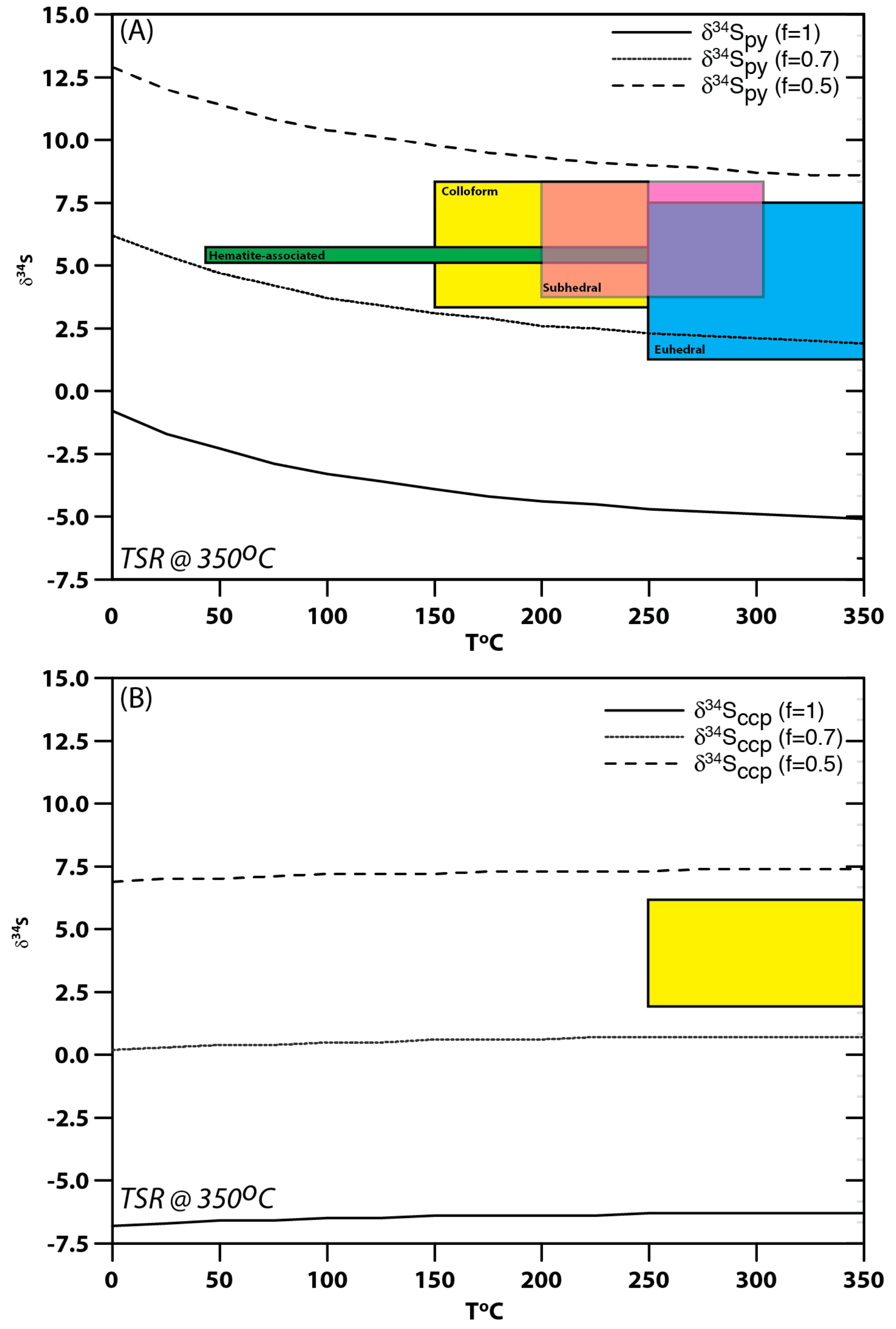
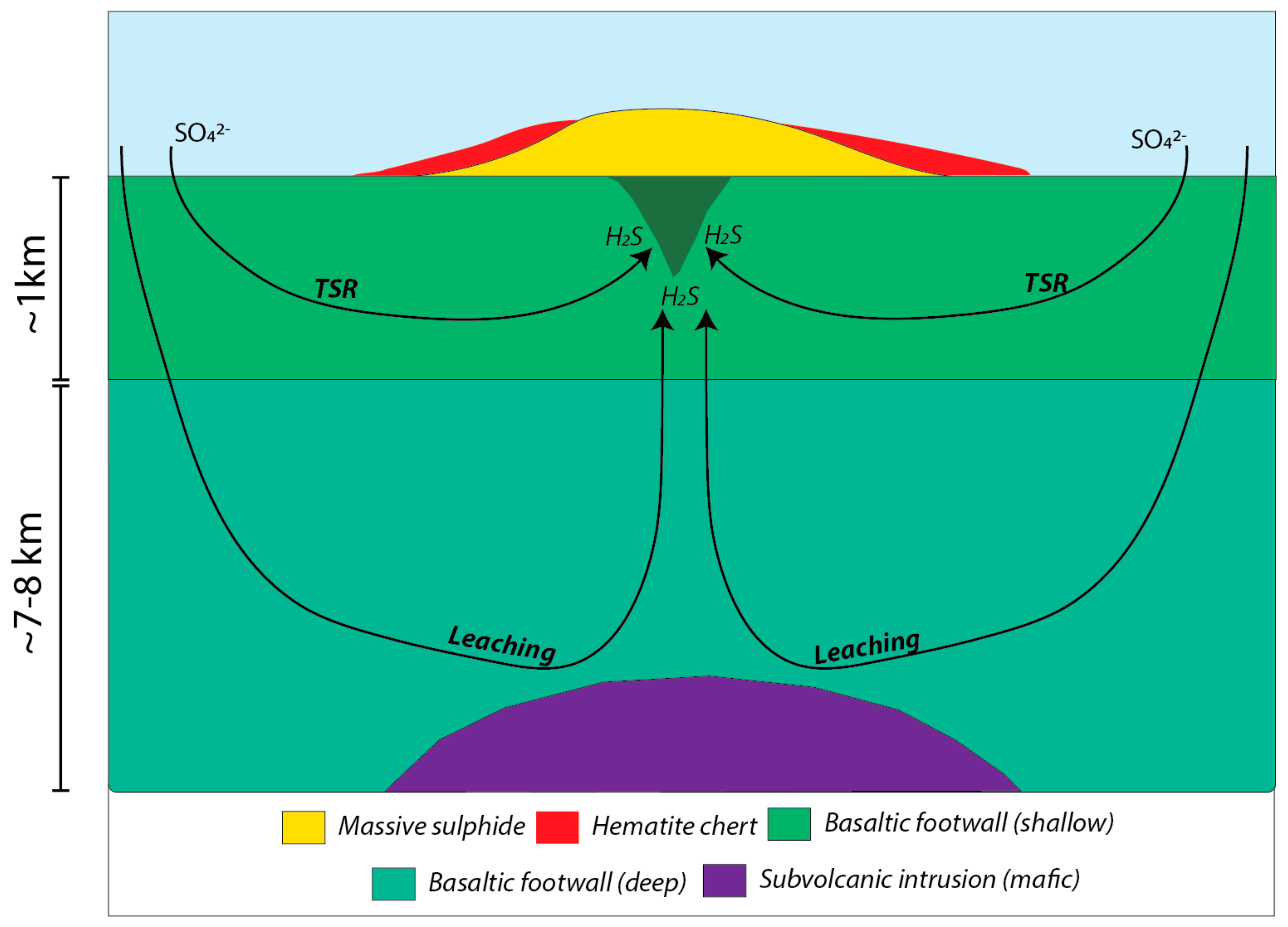
6.2. Sulphur Sources

Ohmoto and Rye [32] and Ohmoto and Goldhaber [33] have outlined the following as potential sources of reduced sulphur (H2S) for VMS (and other hydrothermal) deposits: (1) H2S generated from bacterial sulphate reduction (BSR) of seawater sulphate; (2) H2S generated from thermochemical sulphate reduction (TSR) of seawater sulphate; and (3) and igneous sulphur either via input of sulphur from magmatic fluids/volatiles and/or through stripping of the sulphur from basement rocks by hydrothermal fluids.
Bacterial sulphate reduction (BSR) is a common process that takes place in many lower temperature (<150 °C) hydrothermal systems where thermophillic bacteria biogenically reduce seawater sulphate (SO42−) to sulphide (H2S) [34]. 32S is kinetically favoured over 34S during BSR, resulting in negative δ34S values in sulphide [33]. However, all δ34S values obtained from sulphides in the Ice samples are positive, with the lowest value being +1.8‰. Additionally, the assemblages of the Ice deposit indicate deposition from fluids likely in excess of 150 °C [22,23,24,28] and above temperatures of ~100 °C where direct influence of sulphate reducing bacteria in hydrothermal systems can be considered negligible [33,34]. Furthermore, biogenically reduced sulphur results in the deposition of sulphides with distinct textures, such as framboidal pyrite, and these textures are absent in the Ice sulphides. Taken together, the lack of isotopic and textural evidence for BSR suggests that BSR was not a significant source of reduced sulphur in the Ice deposit.
Despite the unlikelihood of BSR playing a role in the Ice deposit sulphur budget, the lower δ34S values found in both euhedral pyrite and chalcopyrite (Figure 12) requires a source with low values. The lower values of sulphur isotopes are consistent with magmatic sulphur, which typically has values of δ34S = 0 ± 3‰ [32,33]; however, deciphering magmatic sulphur from a magmatic fluid versus that leached from an igneous source is difficult. In VMS associated with magmatic fluids, however, the δ34S of sulfides is often negative (<−3‰), consistent with disproportionation of SO2 into the magmatic-hydrothermal fluid during magmatic degassing [35,36]; the values at Ice are not this low. In addition, VMS deposits with magmatic contributions often have distinctive epithermal suite (As-Sb-Hg-Au-Ag) element enrichments, sulfosalt-rich assemblages, and aluminous alteration assemblages [37,38,39,40], features absent in the Ice deposit, suggesting that direct magmatic fluid input of S was not important.
The lower δ34S values present in some Ice pyrite and chalcopyrite samples is more consistent with a leached igneous sulphur source, and is consistent with both the geological setting and the type of deposit. The Campbell Range formation basalts have normal mid-ocean ridge basalt (N-MORB) to back-arc basin basalt (BABB) signatures [11] and it is reasonable to assume that these samples would have sulphur isotope signatures similar to modern N-MORB and BABB, with values that are ~δ34S = 0‰ [41,42,43,44]. Leaching of the basement rocks from the Campbell Range could therefore account for some of the lower values of δ34S found in some of the Ice pyrite and chalcopyrite (Figure 12; Table 1).
A leached igneous source, however, does not explain some of the higher sulphur isotope values in the Ice deposit (i.e., those with δ34S >> 0‰), requiring an additional sulphur source. The most viable source of heavier sulphur is that formed via thermochemical sulphate reduction of seawater sulphate (TSR). Thermochemical sulphate reduction is effective high temperature (>200 °C) hydrothermal fluids containing seawater sulphate interact with wall rocks [45,46,47]. Commonly, iron, or some another reducing agent, will react with the sulphate in the fluid and result in H2S formation (e.g., Reference [47]):
HSO4 + 8FeO(rock) + H+ → H2S + 4Fe2O3
The mineral assemblages at Ice, including its Cu-rich assemblage suggest the fluids that it formed from were of high temperature (~200–350 °C), temperatures where TSR is known to be effective [45,46,47]. Furthermore, the mafic volcanic rocks of the Campbell Range Belt contain abundant iron [11], which would have been a reducing agent for circulating seawater sulphate [33,45,46,47].
To model and test the role of TSR, we have utilized the equations of Ohmoto and Rye [32] and Ohmoto and Goldhaber [33]. The fractionation of sulphur isotopes between seawater sulphate and H2S during TSR is a function of temperature:
1000 ln α H 2 S SO 4 =   A × 10 6 T 2   +   B × 10 3 T   +   C   =   δ 34 S H 2 S     δ 34 S SO 4
where α H 2 S SO 4 = fractionation factor (the ratio of sulphide to sulphate during TSR), T = temperature in Kelvin, δ 34 S SO 4 is the sulphur isotope composition seawater sulphate; A, B, and C are constants; and δ 34 S H 2 S is the sulphur isotope composition of H2S generated from TSR. The fractionation factor is also influenced by temperature as given by Equation (4):
α H 2 S SO 4   =   e 5.26   ×   10 6 / T 2 1000
Given the Cu-rich assemblages at Ice, and the fact that TSR occurs at depth, it is likely that TSR took place at higher temperatures, and we have assumed that it has taken place at 350 °C (e.g., References [23,24]), and this yields an α H 2 S SO 4 of 0.9806, which is used to calculate the composition of H2S formed by TSR using:
δ 34 S H 2 S   =   δ 34 S SO 4 ( parent )   +   1000 ( 0.9806 1 )
which relates the sulphur isotope compositions of H2S derived from seawater sulphate as a function of the Rayleigh distillation Equation (6):
δ 34 S SO 4 ( t )   =   ( δ 34 S SO 4 ( t   =   0 )   +   1000 )   ×   f ( 0.9806 ) 1000
Equation (6) further calculates the δ34S-value of SO4 at a certain time ( δ 34 S SO 4 ( t ) ) relative to the parent composition of seawater sulphate ( δ 34 S SO 4 ( t   =   0 ) = δ 34 S SO 4 ( parent ) ). This is a function related to the amount of sulphate reduced to H2S, as measured by f, where f represents the atomic fraction of the parent SO4 ( δ 34 S SO 4 ( t   =   0 ) = δ 34 S SO 4 ( parent ) ) reduced to H2S ( δ 34 S H 2 S ) relative to the original amount of SO4 present. For example, when f = 1, no sulphate has been reduced to sulphide, whereas when f = 0, all sulphate has been reduced to sulphide. In Equations (5) and (6), it has been assumed that the δ 34 S SO 4 ( parent ) = δ 34 S SO 4 ( t   =   0 ) is ~13.2‰ the value for seawater sulphate in the Permian (273–274 Ma) [48,49,50], and f is varied from 1 to 0.5.
The H2S generated for a given f value in (6) is then utilized to calculate the δ34S of the coexisting sulphide phase that precipitated from the fluid, be it pyrite or chalcopyrite using Equation (7):
1000 ln α i H 2 S =   A   ×   10 6 T 2   +   B   ×   10 3 T   +   C   =   δ 34 S i     δ 34 S H 2 S
where α i H 2 S = fractionation factor between the sulphide phase (i) and H2S, T = temperature in Kelvin, δ34Si is the sulphur isotope composition of the sulphide phase in question, A, B, and C are constants, and δ34SH2S is the H2S generated from TSR as calculated using Equation (5). This equation also lets one calculate the composition of the sulphide phase as a function of a cooling fluid (i.e., with changing temperature; Figure 13).
The results of the models are shown in Figure 13 for pyrite and chalcopyrite. Additionally, shown are temperature estimates for the various pyrite types and associations. These temperature estimates are rough estimates based on mineral assemblages and general knowledge of the temperature ranges for such assemblages in VMS hydrothermal systems (e.g., References [23,24,51]). We have assumed that colloform pyrite formed at temperatures of 150–250 °C, euhedral pyrite, and chalcopyrite likely formed at temperatures above 250 °C and likely above 300 °C, respectively, and subhedral pyrite likely overlapped the temperature ranges for the latter assemblages (e.g., 200–300 °C) (see also Section 6.1 for additional arguments). The hematite-associated pyrite was likely associated with low temperature activity (T < 150 °C; [4,24]); however, we have given a broader range from 50 to 250 °C as it is possible that the hematite-rich pyrite represents earlier formed pyrite that formed at higher temperatures, but was influenced and overprinted by late Fe-rich fluids (Figure 11). While these are broad temperature estimates, they are sufficient for the purposes of modeling herein and for illustrating the range of sulphur isotopic values associated with TSR.
Both the results for pyrite and chalcopyrite can be explained partially by TSR, as most of the data, regardless of assemblage, lies between the curves for 30% and 50% TSR (f = 0.7 to 0.5; Figure 12). Euhedral pyrite associated with the middle, highest temperature (>300 °C) paragenetic stage of deposit evolution, however, is shifted towards higher f values meaning that the samples had a much greater contribution of leached, igneous basement sulphur (Figure 13), consistent with mixing of sulphur from isotopically distinct sources (e.g., Figure 14).
Both varying amounts of TSR and mixing of sulphur from TSR and leached igneous sources can explain the variation in sulphur isotopes. It is notable, however, that there are distinct differences in sulphur isotopes as a function of paragenesis and temperature. In general, earlier formed, and likely lower temperature, colloform pyrite (early paragenetically) have higher δ34S, whereas later formed, and likely higher temperature euhedral pyrite and chalcopyrite (middle paragentically) are closer to igneous values (Figure 12 and Figure 13). This paragenetic shift suggests that there was a shift in the source of sulphur isotopes through time and is consistent with the lower temperatures sulphides being derived primarily from TSR, whereas the later, higher temperature sulphides were derived either from TSR but with less sulphate reduced (i.e., lower f), or more likely via an input of lighter sulphur from leached igneous sources (Figure 14). Similar results have been found by Gemmell and Large [52] in the Hellyer deposit, and Gemmell and Sharpe [53] in the modern TAG deposit; the latter modern deposit is remarkably similar to the Ice deposit.
In light of the above we favour a sulphur isotope model for the Ice deposit that involved three stages with varying sulphur isotope sources (Figure 14): (1) an early, low temperature phase (<250 °C) resulting in the deposition of mainly colloform pyrite associated with Zn and lesser Cu, with the majority of sulphur being derived from TSR of seawater sulphate; (2) a high temperature stage (>300 °C) where there was recrystallization of earlier formed pyrite, formation of zoned to unzoned euhedral pyrite, and abundant high temperature chalcopyrite, where the source of sulphur included both TSR and that obtained via high temperature leaching of igneous sulphur from basement rocks; and (3) a final stage that involved a cooling of the hydrothermal system and a late stage of pyrite deposition associated with hematite at low temperatures (<150 °C), where sulphur was once again derived predominantly from TSR.

7. Conclusions

The Ice VMS deposit is a type example of a Cyprus-(mafic)-style VMS deposite hosted by basaltic rocks of the Campbell Range formation (Slide Mountain terrane), Yukon, Canada. The deposit consists of a massive sulphide mound that is underlain by a chlorite-sulphide-hematite-rich stringer zone, which collectively have five sulphide facies (pyrite, pyrite-bornite, pyrite-chalcopyrite, pyrite-hematite, and stringer sulphides). These facies have distinctive mineral assemblage and textural evolution that record the zone refining of an ancient VMS mound, including an early, low temperature (~250 °C) stage dominated by Fe-Zn-Cu mineralization; an intermediate, high temperature (>300 °C) stage dominated by Cu-Fe mineralization; and a late low temperature (<150 °C) stage dominated by Fe mineralization.
In situ, sulphur isotope geochemistry of paragenetically controlled pyrite and chalcopyrite range from δ34S = +1.8‰ to +8.2‰ and δ34S = +1.8‰ to +5.4‰, respectively. The pyrite sulphur isotope geochemistry varies as a function of texture and paragenesis. Paragenetically early colloform pyrite and later formed hematite-associated pyrite have higher δ34S values, whereas more euhedral, chalcopyrite-associated pyrite have lower, albeit overlapping, δ34S values. The variation in δ34S is interpreted to reflect varying contributions of H2S from thermochemical sulphate reduction (TSR) of seawater sulphate and that leached from igneous basement rocks. In addition, lower temperature sulphides that formed early and late in the deposit’s history had greater contributions from TSR, whereas higher temperature sulphides contained a greater input of leached igneous sulphur, similar to some modern and ancient VMS deposits.

Author Contributions

M.J.M. undertook the majority of the petrography, SEM, and SIMS S isotope data presented in this paper as part of a BSc(Hons) thesis at Memorial University of Newfoundland. S.J.P. undertook initial fieldwork, was responsible for project design and execution, undertook preliminary mineralogical research on the deposits, was responsible for the sulphur isotope modeling, and was the primary writer of the manuscript and conversion of the BSc(Hons) thesis of McDonald into this manuscript. G.D.L. was responsible for overseeing analysis of and reduction of the SIMS S isotopic data herein, provided editorial comments, and collaborated on the modeling of the sulphur isotopic data. L.C.P. was responsible for the fieldwork and geological framework for the deposit, and was responsible for the mapping, isopach maps, and geological sections presented in this paper. He guided the field research with S.J.P. as part of this project. G.P. was responsible for sulphur isotope data acquisition and reduction of data.

Funding

Initial stages of this research was undertaken as part of the Ancient Pacific NATMAP project funded by the Geological Survey of Canada and the Yukon Geological Survey, with additional logistical and financial support provided by the Yukon Geological Survey through Don Murphy. This research was also funded by an NSERC Discovery Grant and the NSERC-Altius Industrial Research Chair in Mineral Deposits supported by NSERC, Altius Resources Inc., and the Research and Development Corporation of Newfoundland and Labrador (now InnovateNL) to Piercey. Most of this manuscript was completed while Piercey was a Dobbin Scholar at the Irish Center for Research in Applied Geosciences (iCRAG) at both Trinity College and University College Dublin and supported by the Dobbin Atlantic Scholarship Programme of the Ireland Canada University Foundation.

Acknowledgments

We would like to thank colleagues on research in the Finlayson Lake district including Tom Becker, Doug Eaton, Jill Moore, Jim Mortensen, Don Murphy, Suzanne Paradis, and Jan Peter. Reviews by two anonymous reviewers significantly improved the manuscript and we thank them for their contributions.

Conflicts of Interest

There are no conflicts of interest that can be identified by any author in this manuscript that would influence the results presented herein or the outcome of the research.

References

  1. Galley, A.G.; Koski, R.A. Setting and characteristics of ophiolite-hosted volcanogenic massive sulfide deposits. Rev. Econ. Geol. 1999, 8, 221–246. [Google Scholar]
  2. Adamides, N.G. Diverse modes of occurrence of cyprus sulfide deposits and comparisons with recent analogues. In Cyprus Crustal Study Project: Initial Report, Holes Cy-2 and 2a; Robinson, P.T., Gibson, I.L., Panayiotou, A., Eds.; Paper 85-29; Geological Survey of Canda: Ottawa, ON, Canada, 1987; pp. 153–168. [Google Scholar]
  3. Kean, B.F.; Evans, D.T.W.; Jenner, G.A. Geology and Mineralization of the Lushs Bight Group; Geological Survey of Newfoundland and Labrador, Mineral Development Division: St. John’s, CA, USA, 1995; p. 204. [Google Scholar]
  4. Koski, R.A.; Clague, D.A.; Oudin, E. Mineralogy and chemistry of massive sulfide deposits from the juan de fuca ridge. Geol. Soc. Am. Bull. 1984, 95, 930–945. [Google Scholar] [CrossRef]
  5. Hannington, M.D.; Galley, A.G.; Herzig, P.M.; Petersen, S. Comparison of the tag mound and stockwork complex with cyprus-type massive sulfide deposits. Proc. Ocean Drill. Program Sci. Results 1998, 158, 389–415. [Google Scholar]
  6. Aggarwal, P.K.; Nesbitt, B.E. Geology and geochemistry of the chu chua massive sulfide deposit, British Columbia. Econ. Geol. 1984, 79, 815–825. [Google Scholar] [CrossRef]
  7. Bachinski, D.J. Metamorphism of cupriferous iron sulfide deposits, notre dame bay, newfoundland. Econ. Geol. 1976, 71, 443–452. [Google Scholar] [CrossRef]
  8. Bachinski, D.J. Alteration associated with metamorphosed ophiolitic cupriferous iron sulfide deposits; whalesback mine, notre dame bay, newfoundland. Miner. Depos. 1977, 12, 48–63. [Google Scholar] [CrossRef]
  9. Murphy, D.C.; Mortensen, J.K.; Piercey, S.J.; Orchard, M.J.; Gehrels, G.E. Tectonostratigraphic evolution of yukon. In Paleozoic Evolution of Pericratonic Terranes at the Ancient Pacific Margin of North America, Canadian and Alaskan Cordillera; Vol. Geological Association of Canada Special Paper 45; Colpron, M., Nelson, J.L., Eds.; Geological Association of Canada: St. John’s, CA, USA, 2006; pp. 75–105. [Google Scholar]
  10. Peter, J.M.; Layton-Matthews, D.; Piercey, S.; Bradshaw, G.; Paradis, S.; Boulton, A. Volcanic-hosted massive sulphide deposits of the finlayson lake district, Yukon. In Mineral Deposits of Canada: A Synthesis of Major Deposit-Types, District Metallogeny, the Evolution of Geological Provinces, and Exploration Methods; Special Publication 5; Goodfellow, W.D., Ed.; Mineral Deposits Division, Geological Association of Canada: St. John’s, CA, USA, 2007; pp. 471–508. [Google Scholar]
  11. Piercey, S.J.; Murphy, D.C.; Creaser, R.A. Lithosphere-asthenosphere mixing in a transform-dominated late paleozoic backarc basin: Implications for northern cordilleran crustal growth and assembly. Geosphere 2012, 8, 716–739. [Google Scholar] [CrossRef]
  12. Piercey, S.J.; Nelson, J.L.; Colpron, M.; Dusel-Bacon, C.; Simard, R.-L.; Roots, C.F. Paleozoic magmatism and crustal recycling along the ancient pacific margin of north america, northern cordillera. In Paleozoic Evolution and Metallogeny of Pericratonic Terranes at the Ancient Pacific Margin of North America, Canadian and Alaskan Cordillera; Vol. Geological Association of Canada Special Paper 45; Colpron, M., Nelson, J.L., Eds.; Geological Association of Canada: St. John’s, NL, Canada, 2006; pp. 281–322. [Google Scholar]
  13. Piercey, S.J.; Paradis, S.; Murphy, D.C.; Mortensen, J.K. Geochemistry and paleotectonic setting of felsic volcanic rocks in the finlayson lake volcanic-hosted massive sulfide (vhms) district, Yukon, Canada. Econ. Geol. 2001, 96, 1877–1905. [Google Scholar]
  14. Plint, H.E.; Gordon, T.M. The slide mountain terrane and the structural evolution of the finlayson lake fault zone, southeastern Yukon. Can. J. Earth Sci. 1997, 34, 105–126. [Google Scholar] [CrossRef]
  15. Mortensen, J.K. New u-pb ages for the slide mountain terrane in southeastern Yukon territory. In Radiogenic Age and Isotopic Studies: Report 5; Paper 91-2; Geological Survey of Canada: St. John’s, CA, USA, 1992; pp. 167–173. [Google Scholar]
  16. Becker, T. Assessment Report Describing Geological Mapping, Prospecting, Soil Geochemistry, and Diamond Drilling on the Ice Property in the Watson Lake Mining District, Yukon Territory; Unpublished Report for Expatriate Resources Ltd.; Expatriate Resources Ltd.: Vancouver, BC, USA, 1998. [Google Scholar]
  17. Moore, J.; Bradshaw, G.; Duncan, R. Re Evaluation of the Ice Massive Sulfide Deposit; Assessment Report, Yukon Territorial Government; Yukon Territorial Government: Whitehorse, CA, USA, 2003; p. 33.
  18. Eaton, D.; Pigage, L.C. Geological Mapping, Prospecting, Soil Geochemistry, Geophysical Surveys and Diamond Drilling on the Ice Property; Archer, Cathro and Associates (1981) Limited: Vancouver, BC, USA, 1997. [Google Scholar]
  19. Pigage, L.C. Mapping and Stratigraphy at Ice; Unpublished Report for Expatriate Resources Ltd.; Expatriate Resources Ltd.: Vancouver, BC, USA, 1997; p. 5. [Google Scholar]
  20. Clark, A.H.; Blyth, D.M. Reflected-light nomarski interference contrast imaging of dolomite zoning, viburnum trend lead district, southeast missouri; comparisons with cathodoluminescence and electron backscatter microscopy. Econ. Geol. 1993, 88, 1904–1910. [Google Scholar] [CrossRef]
  21. Brueckner, S.M.; Piercey, S.J.; Layne, G.D.; Piercey, G.; Sylvester, P.J. Variations of sulfur isotope signatures in sulfides from the metamorphosed Cu(-Au) volcanogenic massive sulfide ming deposit, Newfoundland Appalachians, Canada. Miner. Depos. 2015, 50, 619–640. [Google Scholar] [CrossRef]
  22. Lydon, J.W. Volcanogenic massive sulphide deposits; Part 2, genetic models. Geosci. Can. 1988, 15, 43–65. [Google Scholar]
  23. Large, R.R. Australian volcanic-hosted massive sulfide deposits; features, styles, and genetic models. Econ. Geol. 1992, 87, 471–510. [Google Scholar] [CrossRef]
  24. Ohmoto, H. Formation of volcanogenic massive sulfide deposits: The kuroko perspective. Ore Geol. Rev. 1996, 10, 135–177. [Google Scholar] [CrossRef]
  25. Roedder, E. The non-colloidal origin of ‘colloform’ textures in sphalerite ores. Econ. Geol. 1968, 63, 451–471. [Google Scholar] [CrossRef]
  26. Barrie, C.D.; Boyce, A.J.; Boyle, A.P.; Williams, P.J.; Blake, K.; Ogawara, T.; Akai, J.; Prior, D.J. Growth controls in colloform pyrite. Am. Mineral. 2009, 94, 415–429. [Google Scholar] [CrossRef]
  27. Eldridge, C.W.; Barton, P.B.; Ohmoto, H. Mineral textures and their bearing on formation of the kuroko orebodies. Econ. Geol. Monogr. 1983, 5, 241–281. [Google Scholar]
  28. Janecky, D.R.; Seyfried, W.E., Jr. Formation of massive sulfide deposits on oceanic ridge crests; incremental reaction models for mixing between hydrothermal solutions and seawater. Geochim. Cosmochim. Acta 1984, 48, 2723–2738. [Google Scholar] [CrossRef]
  29. Tivey, M.K. Generation of seafloor hydrothermal vent fluids and associated mineral deposits. Oceanography 2007, 20, 50–65. [Google Scholar] [CrossRef]
  30. Tivey, M.K.; Humphris, S.E.; Thompson, G.; Hannington, M.D.; Rona, P.A. Deducing patterns of fluid flow and mixing within the tag active hydrothermal mound using mineralogical and geochemical data. J. Geophys. Res. Solid Earth 1995, 100, 12527–12555. [Google Scholar] [CrossRef]
  31. Vaughan, D.J.; Craig, J.R. Sulfide ore mineral stabilities, morphologies, and intergrowth textures. In Hydrothermal Ore Deposits, 2nd ed.; Barnes, H.L., Ed.; John Wiley & Sons: New York, NY, USA, 1997; pp. 367–434. [Google Scholar]
  32. Ohmoto, H.; Rye, R.O. Isotopes of sulfur and carbon. In Geochemistry of Hydrothermal Ore Deposits, 2nd ed.; Barnes, H.L., Ed.; John Wiley & Sons: New York, NY, USA, 1979; pp. 509–567. [Google Scholar]
  33. Ohmoto, H.; Goldhaber, M.B. Sulfur and carbon isotopes. In Geochemistry of Hydrothermal Ore Deposits, 3rd ed.; Barnes, H.L., Ed.; John Wiley and Sons: New York, NY, USA, 1997; pp. 517–611. [Google Scholar]
  34. Jørgensen, B.B.; Isaksen, M.F.; Jannasch, H.W. Bacterial sulfate reduction above 100 °C in deep-sea hydrothermal vent sediments. Science 1992, 258, 1756–1757. [Google Scholar] [CrossRef] [PubMed]
  35. Huston, D.; Relvas, J.; Gemmell, J.; Drieberg, S. The role of granites in volcanic-hosted massive sulphide ore-forming systems: An assessment of magmatic–hydrothermal contributions. Miner. Depos. 2011, 46, 473–507. [Google Scholar] [CrossRef]
  36. Rye, R.O. The evolution of magmatic fluids in the epithermal environment; the stable isotope perspective. Econ. Geol. 1993, 88, 733–752. [Google Scholar] [CrossRef]
  37. Sillitoe, R.H.; Hannington, M.D.; Thompson, J.F.H. High sulfidation deposits in the volcanogenic massive sulfide environment. Econ. Geol. 1996, 91, 204–212. [Google Scholar] [CrossRef]
  38. Mercier-Langevin, P.; Dube, B.; Hannington, M.D.; Davis, D.W.; Lafrance, B.; Gosselin, G. The laronde penna au-rich volcanogenic massive sulfide deposit, abitibi greenstone belt, Quebec: Part I. Geology and geochronology. Econ. Geol. 2007, 102, 585–609. [Google Scholar] [CrossRef]
  39. Dubé, B.; Gosselin, P.; Mercier-Langevin, P.; Hannington, M.; Galley, A. Gold-rich volcanogenic massive sulphide deposits. In Mineral Deposits of Canada: A Synthesis of Major Deposit-Types, District Metallogeny, the Evolution of Geological Provinces, and Exploration Methods; Special Publication, 5, Goodfellow, W.D., Eds.; Mineral Deposits Division, Geological Association of Canada: St. John’s, CA, USA, 2007; pp. 75–94. [Google Scholar]
  40. Hannington, M.D.; Poulsen, K.H.; Thompson, J.F.H.; Sillitoe, R.H. Volcanogenic gold in the massive sulfide environment. In Volcanic-Associated Massive Sulfide Deposits: Processes and Examples in Modern and Ancient Settings; Vol. Reviews in Economic Geology 8; Barrie, C.T., Hannington, M.D., Eds.; Society of Economic Geologists: Littleton, CO, USA, 1999; pp. 325–356. [Google Scholar]
  41. Alt, J.C.; Shanks, W.C., III; Jackson, M.C. Cycling of sulfur in subduction zones: The geochemistry of sulfur in the Mariana Island arc and back-arc trough. Earth Planet. Sci. Lett. 1993, 119, 477–494. [Google Scholar] [CrossRef]
  42. Kusakabe, M.; Mayeda, S.; Nakamura, E. S, O and sr isotope systematics of active vent materials from the mariana backarc basin spreading axis at 18 n. Earth Planet. Sci. Lett. 1990, 100, 275–282. [Google Scholar] [CrossRef]
  43. Sakai, H.; Marais, D.J.D.; Ueda, A.; Moore, J.G. Concentrations and isotope ratios of carbon, nitrogen and sulfur in ocean-floor basalts. Geochim. Cosmochim. Acta 1984, 48, 2433–2441. [Google Scholar] [CrossRef]
  44. Hochstaedter, A.G.; Gill, J.B.; Kusakabe, M.; Newman, S.; Pringle, M.; Taylor, B.; Fryer, P. Volcanism in the sumisu rift, i. Major element, volatile, and stable isotope geochemistry. Earth Planet. Sci. Lett. 1990, 100, 179–194. [Google Scholar] [CrossRef]
  45. Shanks, W.C.; Bischoff, J.L.; Rosenbauer, R.J. Seawater sulfate reduction and sulfur isotope fractionation in basaltic systems: Interaction of seawater with fayalite and magnetite at 200–350∞c. Geochim. Cosmochim. Acta 1981, 45, 1977–1995. [Google Scholar] [CrossRef]
  46. Shanks, W.C., III; Seyfried, W.E., Jr. Stable isotope studies of vent fluids and chimney minerals, southern juan de fuca ridge; sodium metasomatism and seawater sulfate reduction. J. Geophys. Res. 1987, 92, 11387–11399. [Google Scholar] [CrossRef]
  47. Huston, D.L.; Brauhart, C.W.; Drieberg, S.L.; Davidson, G.J.; Groves, D.I. Metal leaching and inorganic sulfate reduction in volcanic-hosted massive sulfide mineral systems; evidence from the paleo-archean Panorama district, Western Australia. Geology 2001, 29, 687–690. [Google Scholar] [CrossRef]
  48. Claypool, C.E.; Hosler, W.T.; Saki, I.R.; Zak, I. The age curves for sulfur and oxygen isotopes in marine sulfate and their mutual interpretation. Chem. Geol. 1980, 28, 199–260. [Google Scholar] [CrossRef]
  49. Kampschulte, A.; Strauss, H. The sulfur isotopic evolution of phanerozoic seawater based on the analysis of structurally substituted sulfate in carbonates. Chem. Geol. 2004, 204, 255–286. [Google Scholar] [CrossRef]
  50. Paytan, A.; Gray, E.T. Chapter 9—Sulfur isotope stratigraphy. In The Geologic Time Scale; Gradstein, F.M., Ogg, J.G., Schmitz, M.D., Ogg, G.M., Eds.; Elsevier: Boston, MA, USA, 2012; pp. 167–180. [Google Scholar]
  51. Lydon, J.W. Some Observations on the Morphology and Ore Textures of Volcanogenic Sulfide Deposits of Cyprus; Paper 84-01A; Geological Survey of Canada: St. John’s, CA, USA, 1984; p. 10. [Google Scholar]
  52. Gemmell, J.B.; Large, R.R. Stringer system and alteration zones underlying the hellyer volcanic-hosted massive sulfide deposit, Tasmania, Australia. Econ. Geol. 1992, 87, 620–649. [Google Scholar] [CrossRef]
  53. Gemmell, J.B.; Sharpe, R. Detailed sulfur-isotope investigation of the tag hydrothermal mound and stockwork zone, 26 degrees n, mid-atlantic ridge. Proc. Ocean Drill. Program Sci. Results 1998, 158, 71–84. [Google Scholar]
  54. Galley, A.G. Characteristics of semi-conformable alteration zones associated with volcanogenic massive sulphide districts. J. Geochem. Explor. 1993, 48, 175–200. [Google Scholar] [CrossRef]
  55. Franklin, J.M.; Gibson, H.L.; Galley, A.G.; Jonasson, I.R. Volcanogenic massive sulfide deposits. In Economic Geology 100th Anniversary Volume; Hedenquist, J.W., Thompson, J.F.H., Goldfarb, R.J., Richards, J.P., Eds.; Society of Economic Geologists: Littleton, CO, USA, 2005; pp. 523–560. [Google Scholar]
Figure 1. Geologic map of Finlayson Lake district, showing locations of volcanogenic massive sulfide deposits [9]. Abbreviations: BCT = Big Campbell thrust, CLT = Cleaver Lake thrust, MCT = Money Creek thrust, NRF = North River Formation, and SMT = Slide Mountain terrane.
Minerals 08 00501 g001aMinerals 08 00501 g001b
Figure 2. Stratigraphic section illustrating relationships of different stratigraphic units in the Yukon-Tanana terrane within the Finlayson Lake region. Abbreviations: ALK = alkaline basalt, Arc = basalts with arc affinity, AT = A-type felsic rocks, BAB = back-arc basin basalt, BON = boninite, MORB = mid-ocean riedge basalt, N-MORB = normal mid-ocean ridge basalt, E-MORB = enriched mid-ocean ridge basalts. Bars near plutons reflect range of U-Pb ages. Modified from Murphy et al. [9]. Campbell in the above figure = Campbell Range formation.
Minerals 08 00501 g002
Figure 3. Geological map of the Ice deposit with location of cross section shown in Figure 5 (modified from References [10,16,19]).
Minerals 08 00501 g003
Figure 4. Stratigraphy of the Ice deposit area showing location of mineralization (modified from References [10,19]).
Minerals 08 00501 g004
Figure 5. Representative cross section (section 11500E) through the Ice deposit (modified from References [10,16]).
Minerals 08 00501 g005
Figure 6. Isopach map of the thicknesses of sulfides from the Ice deposit (modified from References [10,16,19]). Despite minor fault offsets, the isopach pattern is typical of a mound-style VMS deposit.
Minerals 08 00501 g006
Figure 7. Representative photographs of various mineralization types from the Ice deposit. (A) Pyrite-chalcopyrite facies (pyrite—yellow; chalcopyrite—bright yellow). (B) Pyrite-bornite facies with pyrite (yellow) and bornite (purple) cross-cut by chalcopyrite (bright yellow). (C) Pyritic sulphides (yellow) with hematitic chert (red) from near the outer margin of the deposit. (D) Stringer sulphides with stringer pyrite (yellow) in between fragments of brecciated basalt that is altered to chlorite and hematite (green).
Minerals 08 00501 g007
Figure 8. Photomicrographs of mineral assemblages and textures from the Ice deposit. (A) Colloform pyrite locally surrounded by euhedral pyrite grains and partially replaced by sheets of chalcopyrite often forming rounded atoll structures. (B) Euhedral to subhedral pyrite grains and locally pyrite atolls associated with intergrown bornite and sphalerite. (C) Colloform pyrite surrounded by recrystallized, euhedral pyrite proximal to bornite. (D) Partly recrystallized and zoned pyrite grains with relict colloform shapes in their cores with growth zones marked by sphalerite and chalcopyrite grains (sample was etched in nitric acid for 20 s). (E) Zoned pyrite grains with no relict colloform textures, but well-developed zoning with zones marked by trails of chalcopyrite and sphalerite grains; and (F) differential interference contrast image of (E) illustrating the topography and well developed zoning of the pyrite grain (sample in (E,F) was etched in nitric acid for 20 s). (G) Euhedral, inclusion-rich grains of pyrite with interstitial chalcopyrite and lesser sphalerite (sample was etched in nitric acid for 20 s). (H) Euhedral, generally inclusion-free grains of pyrite within a sea of chalcopyrite. (I) Intergrowth of cracked bornite with chalcopyrite associated with euhedral to subhedral pyrite. (J) Specular hematite replacement of pyrite grains associated with euhedral to subhedral pyrite. Abbreviations: Py = pyrite; Py(e) = euhedral pyrite; Py(c) = colloform pyrite; Ccp = chalcopyrite; Brn bornite; Sp = sphalerite; and Hem = hematite.
Minerals 08 00501 g008aMinerals 08 00501 g008b
Figure 9. Scanning electron microsope (SEM) images and semi-quantitative SEM energy dispersive X-ray (SEM-EDX) elemental maps for various mineral assemblages in the Ice deposit. (A) Back scatter electron (BSE) and (B) SEM-EDX elemental maps for pyrite-chalcopyrite atoll structure surrounded by anhedral sphalerite. (C) BSE and (D) SEM-EDX elemental map of atoll to spherulitic pyrite intergrown with bornite. (E) BSE and (F) SEM-EDX elemental may of intergrown pyrite, chalcopyrite and bornite with quartz. (G) BSE and (H) SEM-EDX elemental map of euhedral pyrite with titanite clots in chlorite-altered basalt associated with stringer sulphides. (I) BSE image of fibrous clot of hematite within stringer sulphides. (J) BSE image of galena (bright) inclusions in bornite. (K) BSE image of uraninite (bright; Urn) associated with pyrite (Py) and bornite (Brn). (L) BSE image of monazite (Mon) associated with titanite (Tn) and muscovite (Msc).
Minerals 08 00501 g009
Figure 10. (A) BSE image of well zoned and inclusion-rich pyrite grain showing the location of elemental profile in (C). (B) SEM-EDX semi-quantitative elemental map illustrating the distribution of sphalerite and chalcopyrite inclusions along the various growth zones. (C) Semi-quantitative percent signal of X-ray intensity of various elements across the profile shown in (A). Note the distribution peaks for Cu, Zn, and Si, reflecting the locations of chalcopyrite, pyrite, and silicate inclusions located along growth zones.
Minerals 08 00501 g010
Figure 11. Paragenetic sequence for the sulphide-oxide minerals present in the Ice deposit.
Minerals 08 00501 g011
Figure 12. (A) Histogram and (B) box and whisker plot for the sulphur isotopic data for pyrite and chalcopyrite in the Ice deposit as a function of texture.
Minerals 08 00501 g012
Figure 13. Results from modeling of thermochemical sulfate reduction (TSR) of Permian seawater sulfate for (A) pyrite and (B) chalcopyrite. Details of the model are provided in the text. The results illustrate that TSR played an important role in the sulphur isotope budget of the Ice deposit.
Minerals 08 00501 g013
Figure 14. Sulphur isotope model for the Ice VMS deposit. The model involves two predominant sources of H2S: (1) H2S derived from higher temperature (>300 °C) deep circulating fluids that leached igneous sulphur and yielded sulphides with δ34S~0; and (2) H2S derived from thermochemical sulphate reduction (TSR) of shallowly circulating SO4-rich seawater at lower temperatures (<300 °C) that formed sulphides with δ34S > 0. Both paragenetically early and late sulphides were dominated by H2S derived from TSR and had higher δ34S values. In contrast, sulphides generated during the middle stage of deposit paragenesis had H2S that was derived from both TSR and leached igneous basement, with the latter being of greater importance, resulting in sulphides with lower δ34S values (δ34S~0). This model is based on the concepts outlined by Gemmell and Sharpe [53]. The VMS circulation model is modified after concepts in Galley [54] and Franklin et al. [55].
Minerals 08 00501 g014
Table 1. Sulphur isotope data for pyrite and chalcopyrite from the Ice deposit.
Sample NumberDrill HoleDepthMineralization TypeMineral AnalyzedTextural TypeMineral Associationδ34S
IC2E Py@1ID97-284.53–84.63Py+Brn SMSPyriteColloform PyriteBornite4.3
IC2E Py@2ID97-284.53–84.63Py+Brn SMSPyriteColloform PyriteBornite3.7
IC2E Py@3ID97-284.53–84.63Py+Brn SMSPyriteColloform PyriteBornite4.9
IC4G Py@2ID97-2090.2–90.27Py+Brn+Ccp MSPyriteColloform PyriteBornite8.2
IC4G Py4ID97-2090.2–90.27Py+Brn+Ccp MSPyriteColloform PyriteBornite6.4
IC4G Py@6ID97-2090.2–90.27Py+Brn+Ccp MSPyriteColloform PyriteBornite7.5
IC4G Py10ID97-2090.2–90.27Py+Brn+Ccp MSPyriteColloform PyriteBornite3.1
IC2F Py7ID97-286.97–87.07Py+Ccp MSPyriteColloform PyritePyrite5.0
IC2E Py8ID97-284.53–84.63Py+Ccp SMSPyriteEuhedral PyriteBornite3.9
IC3J Py2ID97-13103.39–103.49Py+Ccp SSPyriteEuhedral PyriteChalcopyrite4.4
IC3H Py1ID97-1395.25–98.15Py+Ccp SSPyriteEuhedral PyriteChalcopyrite1.8
IC3H Py3ID97-1395.25–98.15Py+Ccp SSPyriteEuhedral PyriteChalcopyrite5.3
IC2E Py1ID97-284.53–84.63Py+Brn SMSPyriteEuhedral PyritePyrite6.0
IC2E Py2ID97-284.53–84.63Py+Brn SMSPyriteEuhedral PyritePyrite3.1
IC2E Py6ID97-284.53–84.63Py+Brn SMSPyriteEuhedral PyritePyrite4.4
IC2E Py7ID97-284.53–84.63Py+Brn SMSPyriteEuhedral PyritePyrite3.1
IC2M Py1ID97-2134.97–135.1Py SSPyriteEuhedral PyritePyrite5.8
IC2M Py3ID97-2134.97–135.1Py SSPyriteEuhedral PyritePyrite5.9
IC4G Py@1ID97-2090.2–90.27Py+Brn+Ccp MSPyriteEuhedral PyritePyrite7.5
IC4G Py@2ID97-2090.2–90.27Py+Brn+Ccp MSPyriteEuhedral PyritePyrite3.8
IC4G Py@4ID97-2090.2–90.27Py+Brn+Ccp MSPyriteEuhedral PyritePyrite5.0
IC4G Py9ID97-2090.2–90.27Py+Brn+Ccp MSPyriteEuhedral PyritePyrite2.0
IC3J Py1ID97-13103.39–103.49Py+Ccp SSPyriteEuhedral PyritePyrite5.1
IC3J Py3ID97-13103.39–103.49Py+Ccp SSPyriteEuhedral PyritePyrite4.8
IC3J Py4ID97-13103.39–103.49Py+Ccp SSPyriteEuhedral PyritePyrite3.0
IC2F Py@1ID97-286.97–87.07Py+Ccp MSPyriteEuhedral PyritePyrite2.9
IC2F Py@2ID97-286.97–87.07Py+Ccp MSPyriteEuhedral PyritePyrite3.9
IC2F Py@3ID97-286.97–87.07Py+Ccp MSPyriteEuhedral PyritePyrite4.9
IC2F Py4ID97-286.97–87.07Py+Ccp MSPyriteEuhedral PyritePyrite5.7
IC2F Py5ID97-286.97–87.07Py+Ccp MSPyriteEuhedral PyritePyrite4.6
IC2F Py6ID97-286.97–87.07Py+Ccp MSPyriteEuhedral PyritePyrite2.8
IC4G Py@3ID97-2090.2–90.27Py+Brn+Ccp MSPyriteSubhedral PyriteBornite8.1
IC4G Py@5ID97-2090.2–90.27Py+Brn+Ccp MSPyriteSubhedral PyritePyrite4.0
IC3H Py2ID97-1395.25–98.15Py+Ccp SSPyriteSubhedral PyritePyrite3.4
IC2M Py4ID97-2134.97–135.1Py SSPyriteHematized PyriteHematite4.1
IC3H Ccp3ID97-1395.25–98.15Py SSChalcopyriteChalcopyriteBornite3.3
IC3J Ccp3ID97-13103.39–103.49Py+Ccp SSChalcopyriteChalcopyritePyrite5.4
IC3J Ccp4ID97-13103.39–103.49Py+Ccp SSChalcopyriteChalcopyritePyrite5.0
IC3H Ccp1ID97-1395.25–98.15Py+Ccp SSChalcopyriteChalcopyritePyrite4.7
IC3H Ccp4ID97-1395.25–98.15Py+Ccp SSChalcopyriteChalcopyritePyrite3.0
IC3H Ccp5ID97-1395.25–98.15Py+Ccp SSChalcopyriteChalcopyritePyrite3.4
IC3J Ccp1ID97-13103.39–103.49Py+Ccp SSChalcopyriteChalcopyriteChalcopyrite3.5
IC3J Ccp2ID97-13103.39–103.49Py+Ccp SSChalcopyriteChalcopyriteChalcopyrite5.4
IC3H Ccp2ID97-1395.25–98.15Py+Ccp SSChalcopyriteChalcopyriteChalcopyrite5.2
IC2F Ccp 1ID97-286.97–87.07Py+Ccp MSChalcopyriteChalcopyriteChalcopyrite1.8
Notes: Py = pyrite; Ccp = chalcopyrite; Brn = bornite; MS = massive sulphide; SMS = smei-massive sulphide; SS = stringer sulphide.

