Stability of Chromium in Stainless Steel Slag during Cooling

1
Key Laboratory for Ecological Metallurgy of Multimetallic Minerals (Ministry of Education), Northeastern University, Shenyang 110819, China
2
School of Metallurgy, Northeastern University, Shenyang 110819, China
3
WISDRI Engineering & Research Incorporation Limited, Wuhan 430223, China
*
Author to whom correspondence should be addressed.
Minerals 2018, 8(10), 445; https://doi.org/10.3390/min8100445
Submission received: 21 August 2018
/
Revised: 4 October 2018
/
Accepted: 9 October 2018
/
Published: 11 October 2018
(This article belongs to the Special Issue Metallurgical Slags)
Abstract
:The chromium elution behavior of stainless steel (SS) slag depends highly on the chromium distribution, and the molten modification process proved to effectively improve the chromium enrichment in stable phases. However, the phase transformation and variation of chromium stability during the subsequent cooling process is still poorly understood. In this work, the phase composition and chromium distribution of SS slag from different quenching temperatures were experimentally studied, and the stability of chromium-bearing phases was evaluated using standard leaching tests. The results indicated that dicalcium silicate and spinel phases had formed in the molten slag at 1600 °C, while the dicalcium silicate disappeared and the phases of merwinite and melilite precipitated when the temperature decreased from 1600 to 1300 °C (at a rate of 5 °C/min). During this cooling process, the chromium migrated from other phases into the spinel, significantly suppressing the chromium elution. The leaching results also demonstrated that the potential chromium-bearing phases of glass, dicalcium silicate and merwinite are unstable and are presumably the main source of chromium release. The treated SS slag meets the requirements for the utilization of chromium-bearing slag in the cement and brick industries.
1. Introduction
Stainless steel (SS) slag is generated during the SS production process and discharged to disposal pits that occupy large areas. Calcium oxide is a major component in SS slag, which originates from the addition of lime as flux during the processing of the steel. This is followed by SiO2. Silicon is added during the metal processing to prevent chromium oxidation; it is also formed during the deoxidation of the steel. The third dominant composition in the slag is MgO, which originates from the addition of dolomite as flux and from the refractory lining of the furnace. Some chromium in molten steel can be oxidized during the smelting process forming chromium oxides, and the content of Cr2O3 in SS slag is commonly in the range of 2% to 10% [1,2]. Unlike other metallurgical slags, the potential risk of chromium release from SS slag causes serious environmental concerns which makes it difficult to use as a resource.
Chromium elution behavior is closely related to its distribution in SS slag [3,4]. Many studies [5,6,7,8] reported that the phases of SS slag mainly include dicalcium silicate (Ca2SiO4), merwinite (Ca3MgSi2O8), melilite (Ca2MgSi2O7 and Ca2Al2SiO7), periclase (MgO) and spinel (Mg(Al,Cr)2O4). Chromium can be eluted and oxidized to the toxic hexavalent state (Cr6+) in the natural environment when it exists in unstable phases [9,10,11]. Samada et al. [12] investigated the leaching behavior of chromium from SS slag into seawater, proposing that the chromium-bearing Ca2SiO4 phase is the main source of chromium release in marine systems. Spinel was considered to be a target phase for chromium sequestration due to its excellent stability in both acid and alkaline environments [12,13,14,15,16,17]. The studies by Kilau [18] and Garcia-Ramos [19] showed that the leachability of chromium can be suppressed by promoting the formation of the spinel phase in a CaO-SiO2-Cr2O3-(MgO) slag system. Carbonation treatment for metallurgical slag is regarded as a promising approach for toxic metal sequestration, while the leachability of chromium was reported to not be significantly affected by carbonation [20]. Moreover, it was proven that molten modification using spinel forming agents, such as Al2O3, can accelerate spinel crystallization at up to around 1600 °C [21], while the phase transformation and variation of chromium stability during the subsequent cooling process are still not clear.
Rapid cooling from high temperature by water granulation can form an amorphous structure of slag [22], which could encapsulate metals and thereby lower the solubility of heavy metals [17]. This was attributed to the formation of a stable silica network structure that can repel water and suppress chromium ion elution [23]. However, Engstrom et al. [24] reported that chromium became more reactive in the presence of some chromium-bearing metastable phases during a rapid cooling process, so that the chromium pollution risk remains. The difference in the quenching temperature that researchers employed may be a primary reason for the disagreement.
To clarify this problem and provide some helpful experiences on SS slag remediation, the phase composition of the SS slag and the chromium distribution from different quenching temperatures 1600, 1500, 1400 and 1300 °C were experimentally investigated in this study. Moreover, a standard leaching test was carried out and the stability of various chromium-bearing phases was evaluated.
2. Experiments
2.1. Experimental Sample and Preparation
Our previous research [20] has proved that molten modification using an Al2O3 can promote the enrichment of chromium in a spinel phase in SS slag and reduce the leaching of chromium in an aqueous solution. On the basis of these findings, an Al2O3 modified slag, based on the composition of an AOD (argonoxygen decarburization) slag, was adopted as the raw material, with the chemical composition and basicity (CaO/SiO2) as listed in Table 1.
2.2. Experiment Procedure
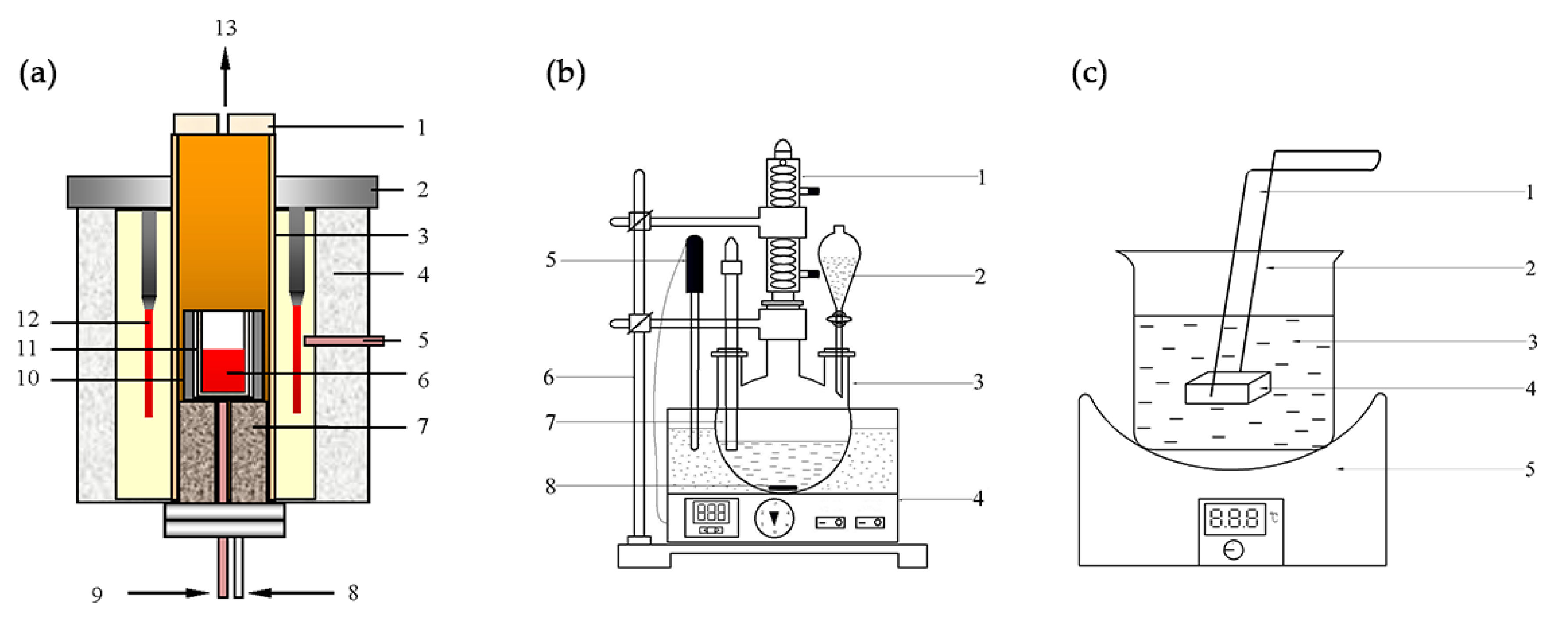
A mass of 15 g slag, with an Al2O3 content of 12%, was poured into a molybdenum crucible positioned inside a graphite crucible. The graphite crucible was then placed in the constant-temperature zone of a furnace. High-quality argon (>99.99%) was injected from the bottom of the furnace to protect the samples from being oxidized. The slags were heated to 1600 °C and held for 30 min to achieve a fully molten state. After that, the temperature was decreased with a fixed cooling rate of 5 °C/min, and the molybdenum crucible was taken out from the furnace when the temperature reached the predetermined values (1600, 1500, 1400 and 1300 °C) and quenched using water. The experimental apparatus used in this study is illustrated in Figure 1.
After the slag samples were separated from the molybdenum crucibles, an X’Pert Pro diffractometer (Kα-Cu) (Philips, Amsterdam, The Netherlands) was used for an X-ray diffraction (XRD) analysis to determine the phase composition of the experiment samples. An Ultra Plus scanning electron microscopy equipped with an energy dispersive spectrometer (SEM-EDS, detection limit of EDS is 0.1%) (HITACHI, Tokyo, Japan) was conducted to investigate the microstructure and the elemental composition in each phase of the samples. This EDS analysis was carried out for 15 different fields of SEM at an amplification factor of 1000. The mass fraction of the precipitated phase was calculated using the mass conservation principle and the linear least squares methods, which are given as follows:
where Xn is the mass fraction of a specific phase in the sample (%), tn is the mass fraction of a specific element in the phase (%), and mn is the mass fraction of a specific element in the experimental slag (%). The calculated mass fraction of the phases was normalized using Equation (3) to ensure the cumulative value equals 100%.
where is the normalized mass fraction of a specific phase (%).
The distribution ratio of chromium in various phases can be obtained from the precipitated fraction of each phase combined with the chromium content dissolved in the corresponding phases. Thus, the enrichment degree of chromium (DCr,i) in a specific phase in a sample can be defined as
where (%Cr)i is the chromium content in a specific phase.
To evaluate the chromium stability in samples quenched from different temperatures, a leaching test was conducted based on the “Standards of the Environmental Protection Industry of the People’s Republic of China HJ/T 299-2007”, and the experimental apparatus employed can be seen in Figure 1b. A mass of 5 g samples was crushed until its particle size was smaller than 74 μm. Then, the sample powder was poured into 50 mL acid solution (mass ratio 2:1 of sulfuric acid and nitric acid) at a pH value of 3.2. After 18 h, the leachate was separated by filtrating in a vacuum system. The amount of chromium in the leachate was determined by ICP-OES (Induced Coupled Plasma-Optical Emission Spectroscopy, detection limit 0.01 mg/L) (Thermo Fisher Scientific, Waltham, MA, USA). Three repetitions were performed for each sample.
Furthermore, in order to study the stability of various chromium-bearing phases in SS slag, some lumps samples were polished using a polisher and several types of abrasive paper to obtain a smooth flat surface. The samples were held using a Teflon holder and immersed and constantly shaken in the same solution (see Figure 1c). After 18 h, the lumps were removed from the vessel and subsequently washed with deionized water, which was performed carefully to avoid any substantial change in the surface eroded by the solution. A gold spraying process was applied to the flat surface of lumps after a leaching test to obtain the conductivity for the subsequent SEM-EDS analysis.
3. Results and Discussion
3.1. Phase Transformations
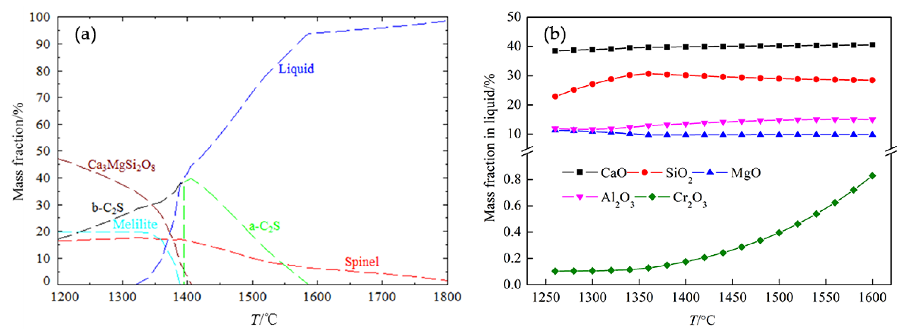
The phase transformations in the studied slag during a cooling process were simulated using FactSage 7.0 software (developed jointly between Thermfact/CRCT and GTT-Technologies, version 7.0, Montreal, Canada-Aachen, Germany) for Gibbs energy minimization. The selected databases were FToxid, FToxid-slagA, FToxid-Mel, FToxid-spinA and FToxid-C2S, respectively. As shown in Figure 2a, the theoretically predicted phases that may precipitate in the temperature range from 1800 to 1200 °C are spinel ((MgAl,Cr)2O4), dicalcium silicate (Ca2SiO4), merwinite (Ca3MgSi2O8), and melilite (Ca2MgSi2O7 and Ca2Al2SiO7). The spinel phase can exist in molten slag above 1600 °C, and with a temperature decrease a dicalcium silicate phase subsequently forms. When the temperature is around 1400 °C, merwinite and melilite phases may precipitate, and a crystal transformation of dicalcium silicate may occur. The mass fraction of some of the main components in the liquid phase at equilibrium was calculated and the results are plotted in Figure 2b. It can be seen that the Cr2O3 content in the liquid phases changes with the temperature, and is less than 0.1% at around 1300 °C. All this suggests that quenching temperature has a significant effect on the phase composition of SS slag and chromium distribution.
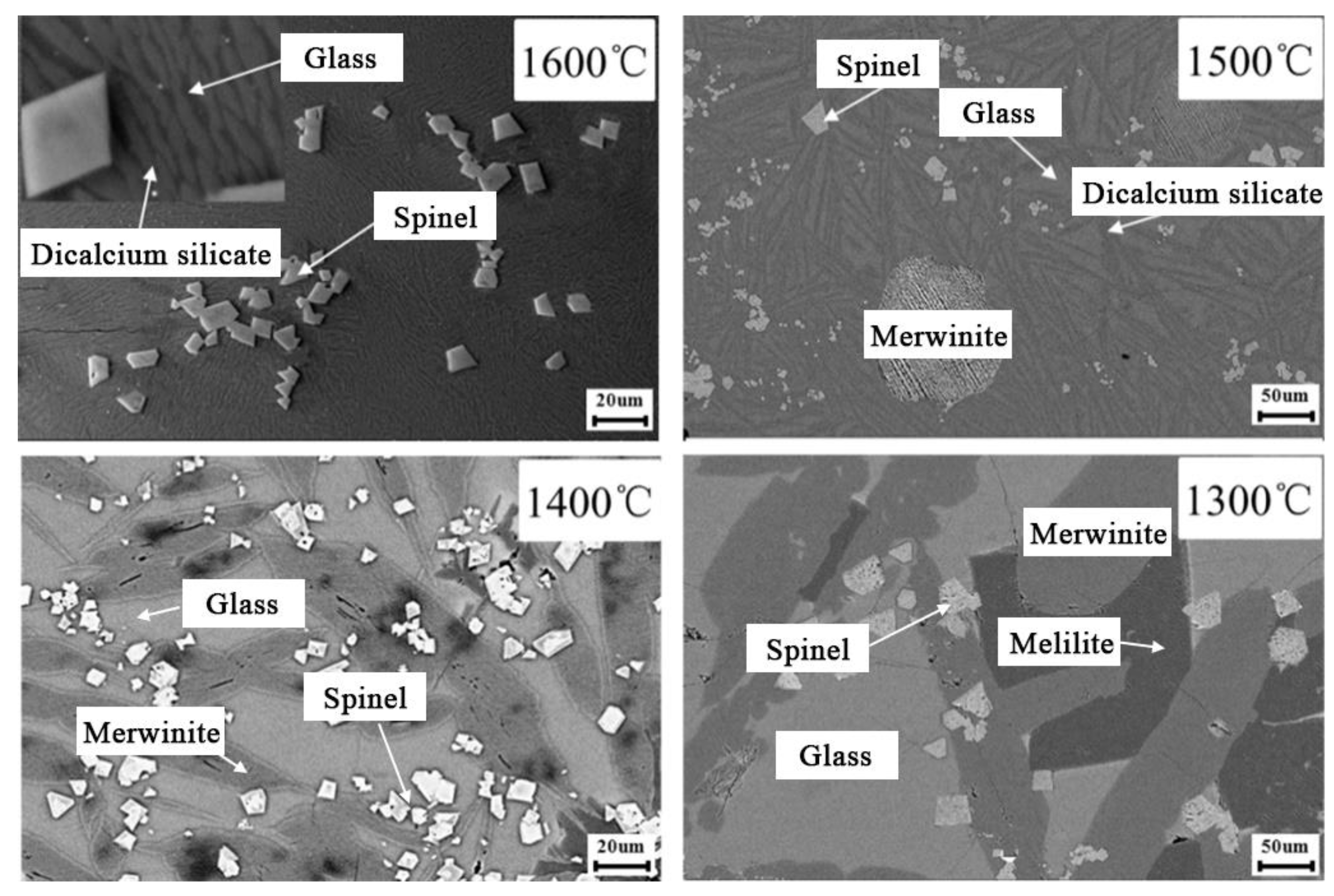
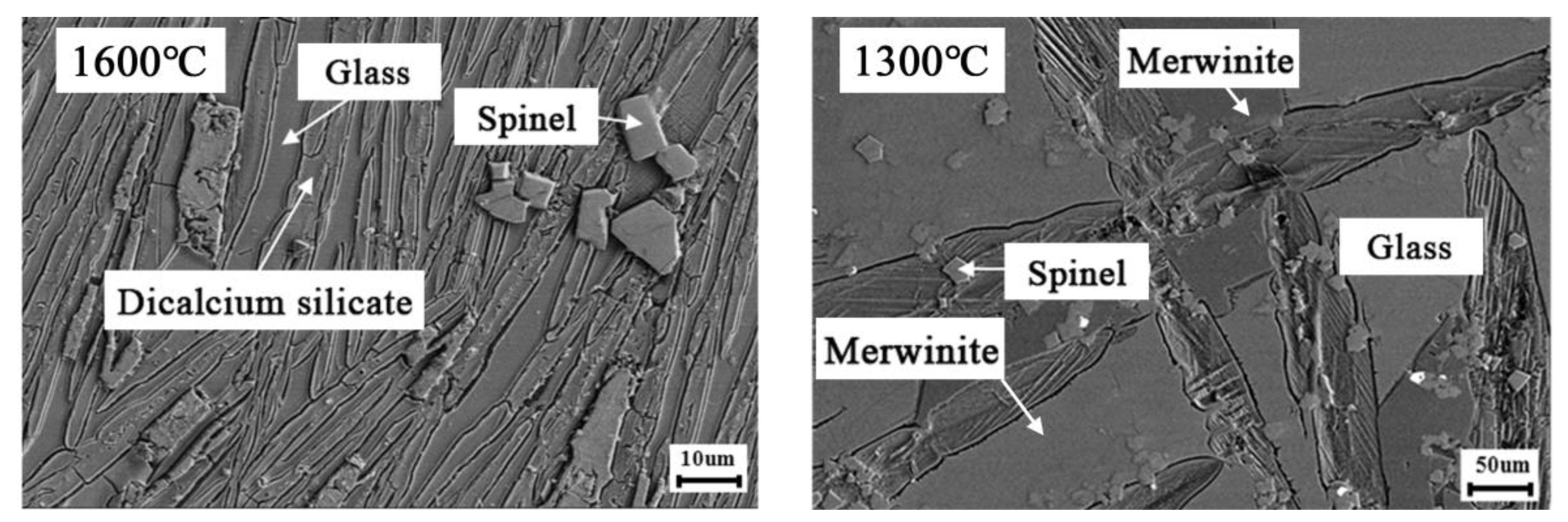
Figure 3 gives the SEM images of the samples quenched from different temperatures of 1600, 1500, 1400 and 1300 °C, respectively. The results indicate that the phase composition obviously changes with a variation in the quenching temperature. According to Figure 3 and the EDS results given in Table 2, it was found that the spinel crystals had formed at 1600 °C, and a dicalcium silicate phase had precipitated from the glass. When the quenching temperature was 1500 °C, the dicalcium silicate phase became larger and the merwinite phase appeared. Some glass phase still existed in the sample. When the quenching temperature was lowered to 1400 °C, only three phases of glass, spinel, and merwinite, respectively, were visible in the SEM image. The dicalcium silicate phase is not detectable in either the SEM-EDS or the XRD analysis. A melilite phase was found in the sample that was quenched from 1300 °C, and the principal phases found are glass, spinel, merwinite, and melilite, respectively.
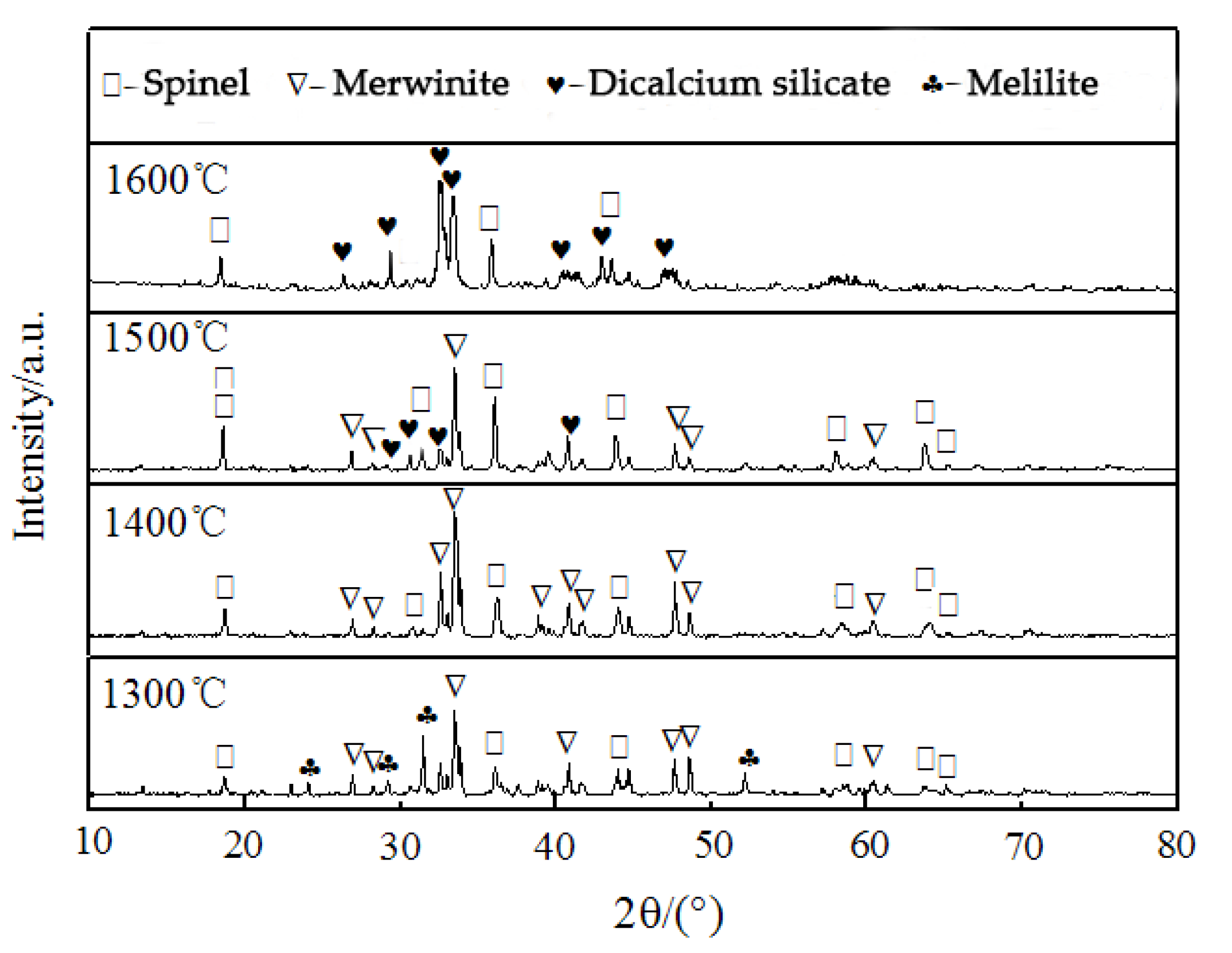
An XRD analysis was performed on the samples quenched from various temperatures. The results are shown in Figure 4 and are consistent with what can be concluded from the corresponding SEM-EDS analysis. The variation of phase composition with the quenching temperature proved that certain phase transformations occur during the cooling process. On the basis of these findings, it was suggested that the chromium distribution may be controlled by controlling cooling conditions, and, the stability of chromium may be further improved after a meltcomposition modification.
3.2. Chromium Distribution
It was found, as listed in Table 2, that the chromium present in the 1600 °C-quenched sample mainly existed in the spinel, glass, and dicalcium silicate phases. When the quenching temperature was 1500 °C, the chromium content in dicalcium silicate was below the detection limit of EDS, while the precipitated merwinite contained some chromium. As the quenching temperature was further lowered to 1400 °C, the chromium content in the glass phase was smaller, while the remaining chromium mainly enriched in the spinel phase. At 1300 °C, no chromium was detected in other phases apart from the spinel.
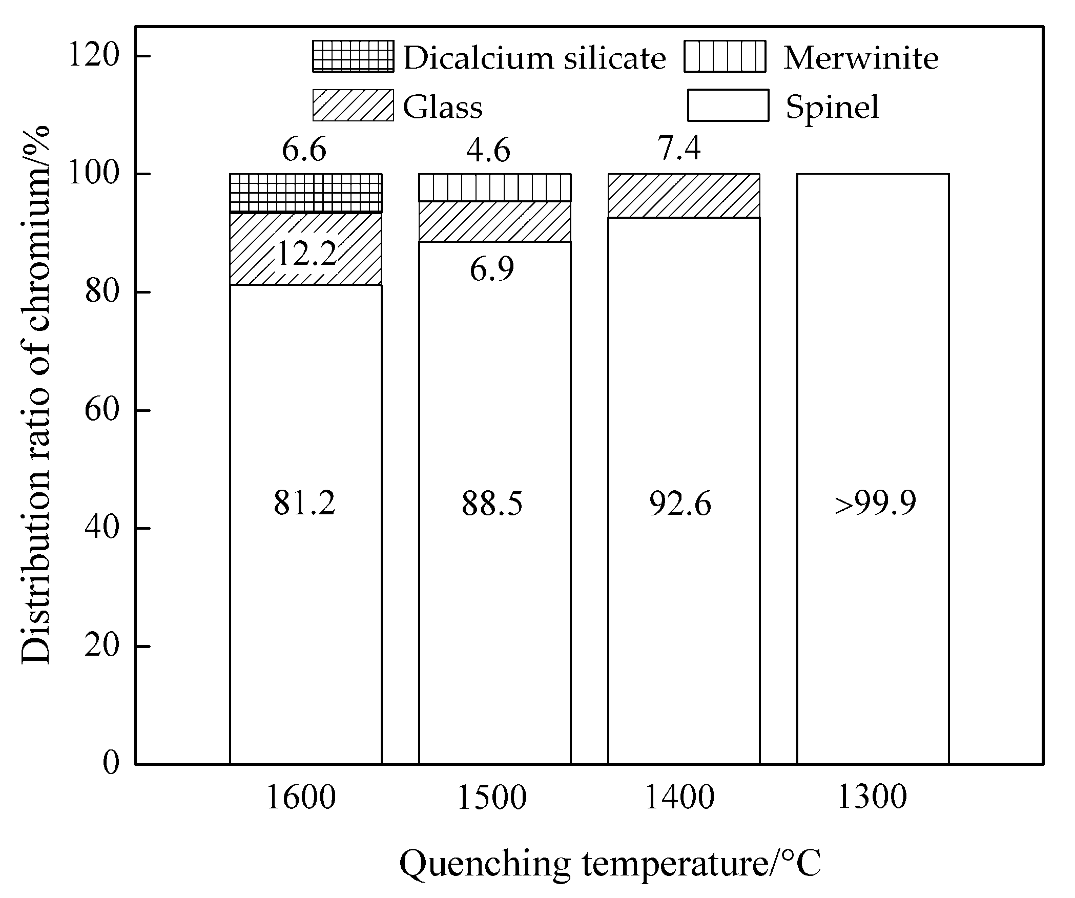
The average values of the degree of enrichment of chromium in the various phases from different quenching temperatures and their corresponding standard deviation (σ) were calculated and are given in Table 3. The distribution ratio of chromium is shown in Figure 5. It can be seen that 81.2% of the chromium existed in the spinel phase for 1600 °C quenching, and approximately 12.2% and 6.6% of the chromium were in the glass and dicalcium silicate phases, respectively. With the decrease in the quenching temperature, some chromium was found in the spinel rather than in the other phases, i.e., there was a higher degree of enrichment chromium in the spinel phase. As the quenching temperature decreased to 1300 °C, almost all the chromium existed in the spinel phase. The explanations for the different final forms in which the chromium exists after quenching could be as follows: The growth of a spinel crystal during the cooling process requires Cr2O3 feeding, which causes a driving force for chromium transported from other phases to the spinel. Moreover, the solid solubility of Cr2O3 in the precipitated silicate phases decreases with temperature, eliminating the Cr2O3 from the merwinite and melilites [25,26,27].
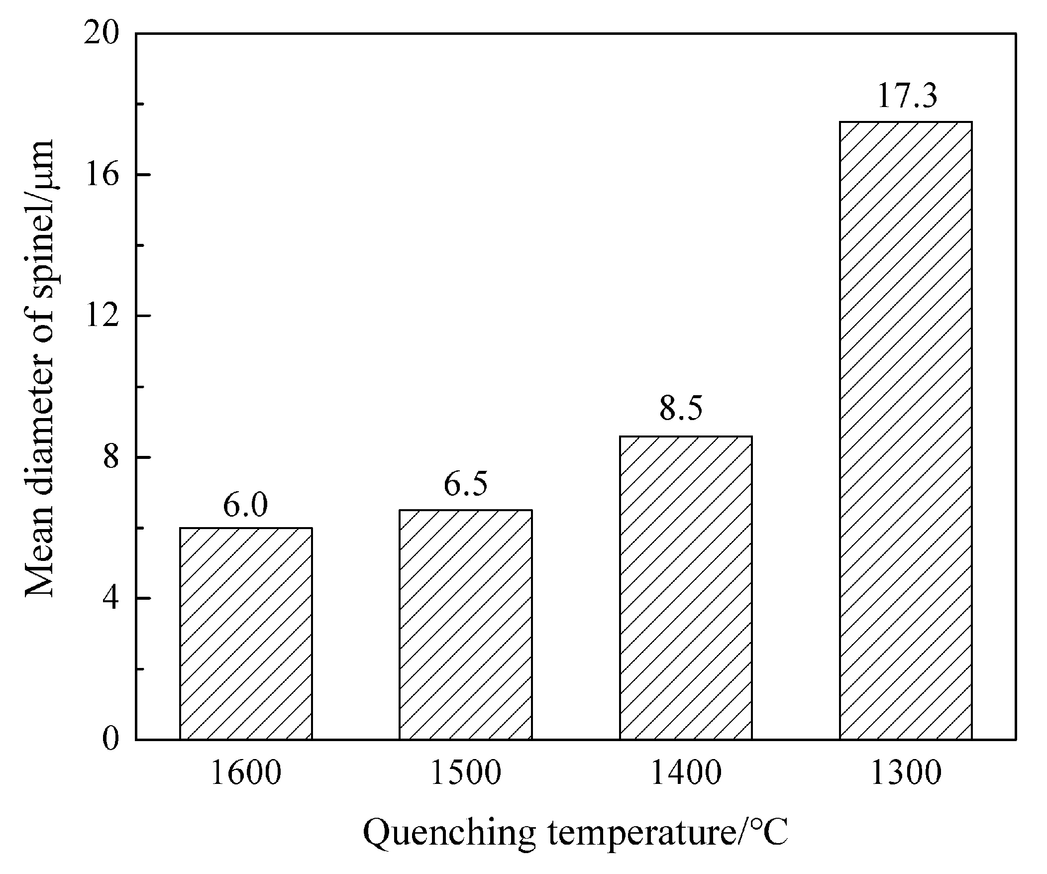
Based on the above discussion, the growth behavior of spinel in the cooling process was investigated. The mean diameter of the spinel was determined by analyzing the spinel at 15 different fields with the image analysis software Image-Pro Plus 6, with results as shown in Figure 6. It was found that the mean diameter was around 6.0 μm for quenching 1600 °C and increased when the quenching temperature was decreased to 1300 °C. A rapid increase in spinel size is seen when comparing quenching from 1400 with quenching from 1300 °C, giving a significant increase from 8.5 to 17.3 μm in mean diameter. This increase in spinel size when quenching at lower temperatures is clearly an important factor for chromium migration.
3.3. Chromium Stability Evaluation
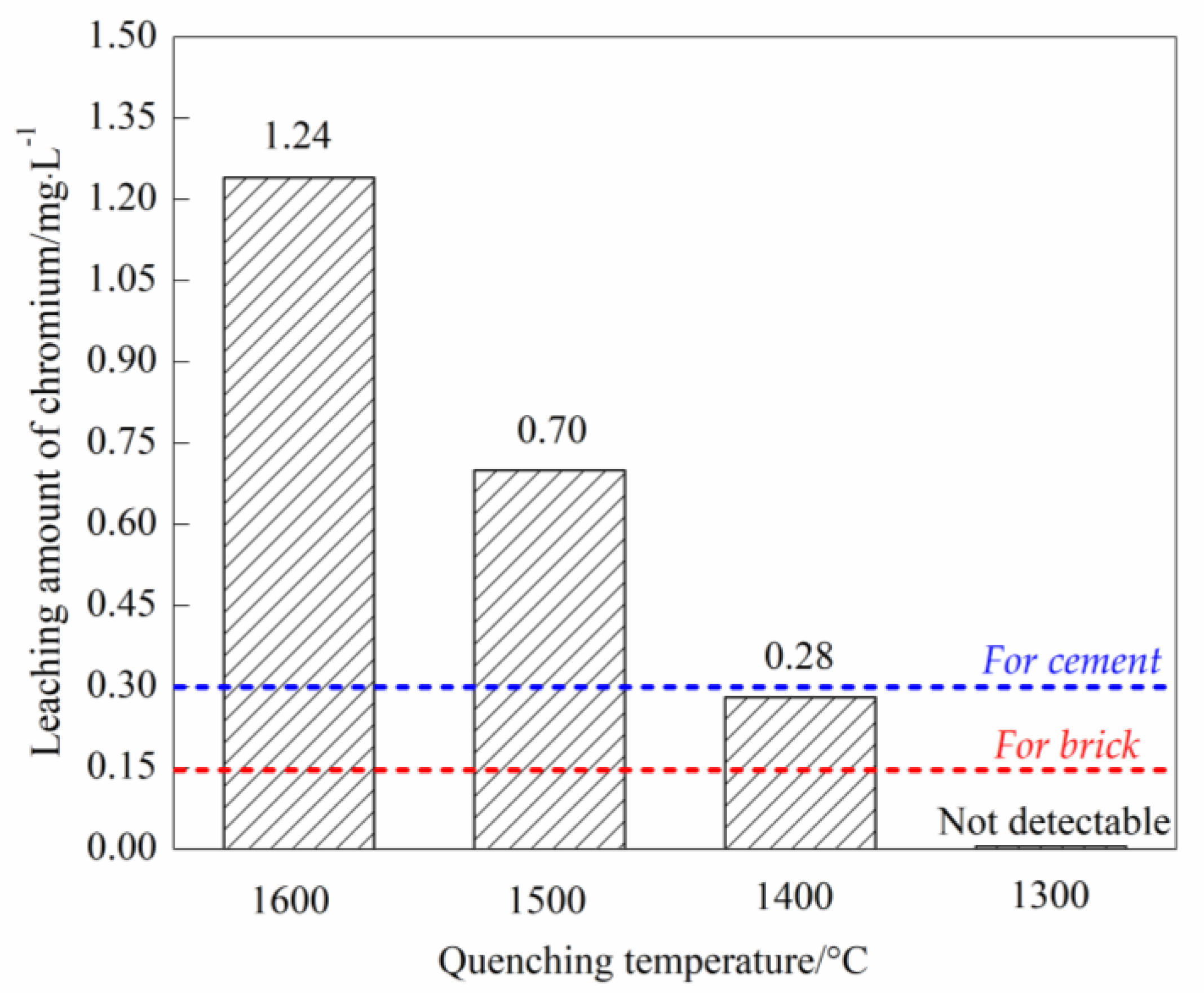
To evaluate the chromium stability of samples quenched from different temperatures, a batch of standard leaching tests was conducted. Figure 7 shows the leaching amount of chromium from the samples quenched from 1600, 1500, 1400 and 1300 °C, respectively. Experimental results indicated that, when the quenching temperature was 1600 °C, the chromium concentration in leachate was 1.24 mg/L, which decreased with lower quenching temperatures. When the sample was quenched from 1300 °C, chromium could no longer be detected in the leachate, which implies a concentration of less than 0.01 mg/L (detection limit of the employed ICP-OES). According to the “environmental protection technical specifications pollution treatment of the chromium residue” by HJ/T 301-2007 of China, the limit for chromium leaching is 0.30 mg/L (blue dash line in Figure 7) and 0.15 mg/L (red dash line in Figure 7) for the utilization of chromium-bearing slag in the cement and brick industries, respectively. Therefore, a well-designed cooling process may suppress chromium elution from SS slag and make this by-product suitable for use as a resource.
The leaching results were in agreement with Samada’s study [12], and the small amount of chromium leached from the sample quenched from 1300 °C is attributed to the high degree of enrichment of chromium in a stable spinel [18,19]. For the purpose of understanding the stability of other chromium-bearing phases precipitated during cooling, a stability diagram of several pure silicates was plotted [28]. Figure 8 gives the amount of calcium leached as a function of the pH value at 25 °C, which could represent the stability of the corresponding silicate. The results indicated that the large amount of calcium may be eluted from the silicates in an acid solution, meaning that the dicalcium silicate, merwinite, and melilite are unstable phases. Chromium contained in these phases would be released along with the decomposition of these phases. Thus, chromium-bearing dicalcium silicate, merwinite, and melilite may be the main sources of chromium elution.
To verify the proposed speculation, lump samples quenched from 1600 °C and 1300 °C, respectively, were selected and corroded for 18 h using a standard acid solution (mass ratio 2:1 of sulfuric acid and nitric acid, pH = 3.2). The morphology of the phases was investigated using SEM-EDS, and the SEM images are given in Figure 9. It can be clearly seen that significant cracks formed in the glass and dicalcium silicate phases when quenched from 1600 °C, implying that the two phases were eroded in the acid solution employed. Moreover, the erosion in the dicalcium silicate phase was found to be more severe.
For the samples quenched from 1300 °C and leached for 18 h, the surface of the merwinite phase was seriously eroded, while the melilite and spinel phases kept their original morphology. Based on the above observation, it was concluded that the dicalcium silicate, merwinite, and glass phases were unstable, while the spinel is apparently the target phase for chromium fixation. Therefore, a cooling process preferably ensures a full chromium migration into stable spinel phases.
4. Conclusions
The phase composition and chromium distribution of SS slag quenched from different temperatures were studied, and a batch of standard leaching tests was carried out to evaluate the stability of various chromium-bearing phases. Experimental results showed that the dicalcium silicate and spinel phases could form in the molten slag at 1600 °C. Comparing quenching from 1600°C and 1300 °C when cooling at a rate of 5 °C/min, the dicalcium silicate disappeared in the 1300°C sample, which also showed the presence of precipitated phases of merwinite and melilite. Moreover, the degree of enrichment of chromium in the spinel phase in these samples was 81.2% and >99.9%, respectively, while the chromium elution from SS slag was smaller for lower quenching temperatures. When the quenching temperature was 1300 °C, almost all the chromium existed in the spinel phases and the amount of chromium leached in a standard acid solution (mass ratio 2:1 of sulfuric acid and nitric acid, pH = 3.2) was less than 0.01 mg/L. It was also demonstrated that the elution behavior of chromium from SS slag depends highly on its distribution across the phases. The glass, dicalcium silicate, and merwinite are unstable phases, which may be the main source of chromium release in the acid system, while the spinel is suggested to be a preferable target phase for chromium fixation. Therefore, with the consideration of a non-polluting use of SS slag, the cooling process should be carried out under well-controlled conditions. This work thus provides useful information on SS slag remediation.
Author Contributions
Experiment, Q.Z., L.C. and X.Z.; Data Analysis and Writing—Original Draft Preparation, Q.Z.; Writing, Review and Editing, C.L. and M.J.
Funding
This research was supported by the National Natural Science Foundation of China (No. 51704068), the National Key R&D Program of China (No. 2017YFC0805100) and the Fundamental Research Funds for the Central Universities (No. N172504020).
Acknowledgments
The authors gratefully acknowledge support from the National Natural Science Foundation of China (No. 51704068), the National Key R&D Program of China (No. 2017YFC0805100), the Fundamental Research Funds for the Central Universities (No. N172504020). Ron Zevenhoven of Åbo Akademi University, Turku, Finland, is acknowledged for checking and commenting on the manuscript.
Conflicts of Interest
The authors declare no conflict of interest.
References
- Loncnar, M.; Zupancic, M.; Bukovec, P. The effect of water cooling on the leaching behaviour of EAF slag from stainless steel production. Mater. Tehnol. 2009, 43, 315–322. [Google Scholar]
- Mombelli, D.; Mapelli, C.; Barella, S.; Di Cecca, C.; Le Saout, G.; Garcia-Diaz, E. The effect of microstructure on the leaching behaviour of electric arc furnace (EAF) carbon steel slag. Process Saf. Environ. Prot. 2016, 102, 810–821. [Google Scholar] [CrossRef]
- Mombelli, D.; Mapelli, C.; Barella, S.; Di Cecca, C.; Le Saout, G.; Garcia-Diaz, E. The effect of chemical composition on the leaching behaviour of electric arc furnace (EAF) carbon steel slag during a standard leaching test. J. Environ. Chem. Eng. 2016, 4, 1050–1060. [Google Scholar] [CrossRef] [Green Version]
- Mombelli, D.; Mapelli, C.; Barella, S.; Gruttadauria, A.; Le Saout, G.; Garcia-Diaz, E. The efficiency of quartz addition on electric arc furnace (EAF) carbon steel slag stability. J. Hazard. Mater. 2014, 279, 586–596. [Google Scholar] [CrossRef] [PubMed]
- Wei, D.X.; Xu, A.J.; Dong, D.F.; Tian, N.Y.; Yang, Q.X. Beneficial reuse of EAF slag and its leaching behavior of Cr. Iron Steel 2012, 47, 92–96, (In Chinese with English abstract). [Google Scholar]
- Shi, H.Z.; Wang, R.Y.; Chen, R.H.; Shi, L. Safety analysis of stainless steel slag used as composite cement admixture. J. Build. Mater. 2010, 13, 802–806, (In Chinese with English abstract). [Google Scholar]
- Shen, H.; Forssberg, E.; Nordström, U. Physicochemical and mineralogical properties of stainless steel slags oriented to metal recovery. Resour. Conserv. Recycl. 2004, 40, 245–271. [Google Scholar] [CrossRef]
- Engström, F.; Adolfsson, D.; Samuelsson, C.; Sandström, Å.; Björkman, B. A study of the solubility of pure slag minerals. Miner. Eng. 2013, 41, 46–52. [Google Scholar] [CrossRef]
- Yamaguchi, A. Characteristics and problem of chrome—Containing refractory. China’s Refract. 2007, 16, 3–7, (In Chinese with English abstract). [Google Scholar]
- Lee, Y.; Nassaralla, C.L. Minimization of hexavalent chromium in magnesite—Chrome refractory. Metall. Mater. Trans. B 1997, 28, 855–859. [Google Scholar] [CrossRef]
- Lee, Y.; Nassaralla, C.L. Formation of hexavalent chromium by reaction between slag and magnesite—Chrome refractory. Metall. Mater. Trans. B 1998, 29, 405–410. [Google Scholar] [CrossRef]
- Pillay, K.; Von Blottnitz, H.; Petersen, J. Ageing of chromium(III)-bearing slag and its relation to the atmospheric oxidation of solid chromium(III)-oxide in the presence of calcium oxide. Chemosphere 2003, 52, 1771–1779. [Google Scholar] [CrossRef]
- Samada, Y.; Miki, T.; Hino, M. Prevention of chromium elution from stainless steel slag into seawater. ISIJ Int. 2011, 51, 728–732. [Google Scholar] [CrossRef]
- Real, H.C.; Serrano, A.; Zeifert, B.H.; Ramirez, A.H.; Lopez, M.H.; Ramirez, A. Effect of MgO and CaO/SiO2 on the immobilization of chromium in synthetic slags. J. Mater. Cycles Waste Manag. 2012, 14, 317–324. [Google Scholar] [CrossRef]
- Torres, V.A.; Romero, A.; Zeifert, B.H.; Rivera, J.C.; Sánchez, P.F.; Cruz, A. Stabilization of MgCr2O4 spinel in slags of the SiO2-CaO-MgO-Cr2O3 system. Rev. Metal. Madr. 2006, 42, 417–424. [Google Scholar] [CrossRef]
- Drissen, P.; Ehrenberg, A.; Kuhn, M.; Mudersbach, D. Recent development in slag treatment and dust recycling. Steel Res. Int. 2009, 80, 737–745. [Google Scholar] [CrossRef]
- Tossavainen, M.; Forssberg, E. Studies of the leaching behaviour of rock material and slag used in road construction: A mineralogical interpretation. Steel Res. 2000, 71, 442–448. [Google Scholar] [CrossRef]
- Kilau, H.W.; Shah, I.D. Chromium-bearing waste slag: Evaluation of leachability when exposed to simulated acid precipitation. In Proceedings of the 3th Symposium, Hazardous Industrial Waste Management and Testing, Philadelphia, PA, USA, 7–10 Match 1983. [Google Scholar]
- García-Ramos, E.; Romero-Serrano, A.; Zeifert, B.; Flores-Sánchez, P.; Hallen-López, M.; Palacios, E.G. Immobilization of chromium in slags using MgO and Al2O3. Steel Res. Int. 2008, 79, 332–339. [Google Scholar] [CrossRef]
- Baciocchi, R.; Costa, G.; Polettini, A.; Pomi, R. Effects of thin-film accelerated carbonation on steel slag leaching. J. Hazard. Mater. 2015, 286, 369–378. [Google Scholar] [CrossRef] [PubMed]
- Cao, L.H.; Liu, C.J.; Zhao, Q.; Jiang, M.F. Effect of Al2O3 modification on enrichment behavior of chromium in stainless steel slag. J. Iron Steel Res. Int. 2017, 24, 258–265. [Google Scholar] [CrossRef]
- Tossavainen, M.; Engström, F.; Yang, Q.; Menad, N.; Lidstrom, L.M.; Bjorkman, B. Characteristics of steel slag under different cooling conditions. Waste Manag. 2007, 27, 1335–1344. [Google Scholar] [CrossRef] [PubMed]
- Sakai, Y.; Yabe, Y.; Takahashi, M.; Iizuka, A.; Shibata, E.; Nakamura, T. Elution of hexavalent chromium from molten sewage sludge slag: Influence of sample basicity and cooling rate. Ind. Eng. Chem. Res. 2013, 52, 3903. [Google Scholar] [CrossRef]
- Engstrom, F.; Adolfsson, D.; Yang, Q.; Samuelsson, C.; Bjorkman, B. Crystallization behaviour of some steelmaking slags. Steel Res. Int. 2010, 81, 362–371. [Google Scholar] [CrossRef]
- Cao, L.H.; Liu, C.J.; Zhao, Q.; Jiang, M.F. Growth behavior of spinel in stainless steel slag during cooling process. Metall. Res. Technol. 2018, 115, 114–121. [Google Scholar] [CrossRef]
- Bartie, N.J. The Effects of Temperature Slag Chemistry and Oxygen Partial Pressure on the Behaviour of Chromium Oxide in Melter Slags. Ph.D. Thesis, The University of Stellenbosch, Stellenbosch, South Africa, December 2004. [Google Scholar]
- Albertsson, G.J.; Teng, L.; Engström, F.; Seetharaman, S. Effect of the heat treatment on the chromium partition in CaO-MgO-SiO2-Cr2O3 synthetic slags. Metall. Mater. Trans. B 2013, 44, 1586–1597. [Google Scholar] [CrossRef]
- Barin, I. Thermochemical Data of Pure Substances; part 1; VCH: Weinheim, Germany, 1989. [Google Scholar]
Figure 1.
Illustration of the experimental apparatus used in this study. (a) Furnace. 1—cap; 2—furnace cover; 3—corundum tube; 4—insulation layer; 5—thermocouple A; 6—sample; 7—refractory; 8—gas inlet; 9—thermocouple B; 10—graphite crucible; 11—molybdenum crucible; 12—MoSi2 heating elements; 13—gas outlet. (b) For powder leaching. 1—condenser; 2—liquid inlet; 3—three-necked flask; 4—oil bath pan; 5—thermocouple; 6—retort stand; 7—pH meter; 8—magneton. (c) For lump leaching. 1—Teflon holder; 2—glass beaker; 3—sulfuric acid and nitric acid; 4—lump sample; 5—automatic temperature-controlled electric heater.

Figure 2.
(a) Phase evolution of the studied slag in the temperature range from 1800 to 1200 °C and (b) Mass fraction of components in the liquid phase as a function of temperature.
Figure 2.
(a) Phase evolution of the studied slag in the temperature range from 1800 to 1200 °C and (b) Mass fraction of components in the liquid phase as a function of temperature.

Figure 3.
SEM images of samples quenched from different temperatures.

Figure 4.
XRD patterns of samples quenched from different temperatures.

Figure 5.
Distribution ratio of chromium in phases quenched from different temperatures.

Figure 6.
Mean diameter of spinel quenched from different temperatures.

Figure 7.
Leaching amount of chromium from samples quenched from different temperatures.

Figure 8.
Stability diagram of calcium ion in aqueous solution at 25 °C.

Figure 9.
SEM images of 1600 and 1300 °C-quenched samples after leaching test.


Table 1.
The chemical composition of experimental slag, wt %.
| CaO | SiO2 | MgO | FeO | Al2O3 | Cr2O3 | CaF2 | Basicity |
|---|---|---|---|---|---|---|---|
| 40.8 | 27.2 | 9.0 | 3.0 | 12.0 | 5.0 | 3.0 | 1.5 |
Table 2.
EDS results of each phase in Figure 3, at %.
Table 2.
EDS results of each phase in Figure 3, at %.
| Temperature, °C | Phase | Ca | Mg | Si | Al | Cr | Fe | O |
|---|---|---|---|---|---|---|---|---|
| 1600 | Glass-1 | 17.35 | 4.22 | 5.30 | 12.28 | 0.42 | - | 57.53 |
| Spinel-2 | 1.05 | 12.74 | 0.27 | 10.71 | 15.72 | - | 57.36 | |
| Dicalcium silicate-3 | 21.89 | 4.02 | 13.49 | 1.72 | 0.38 | - | 57.30 | |
| 1500 | Glass-1 | 18.71 | 3.84 | 13.88 | 8.74 | 0.38 | 0.65 | 53.97 |
| Spinel-2 | 0.60 | 14.02 | - | 10.00 | 21.62 | 1.63 | 52.13 | |
| Merwinite-3 | 22.73 | 6.86 | 15.14 | 0.97 | 0.21 | 0.46 | 53.83 | |
| Dicalcium silicate-4 | 24.04 | 2.69 | 14.08 | - | - | 0.52 | 58.67 | |
| 1400 | Glass-1 | 17.66 | 1.93 | 11.08 | 6.13 | 0.28 | 1.58 | 54.77 |
| Spinel-2 | 0.33 | 11.54 | - | 9.00 | 19.45 | 1.57 | 58.11 | |
| Merwinite-3 | 21.23 | 6.58 | 14.49 | - | - | - | 57.88 | |
| 1300 | Glass-1 | 18.32 | 2.26 | 11.54 | 4.24 | - | 1.31 | 58.62 |
| Spinel-2 | 0.39 | 11.65 | - | 9.22 | 17.79 | 1.28 | 59.66 | |
| Merwinite-3 | 21.62 | 5.73 | 14.35 | - | - | - | 58.30 | |
| Melilite-4 | 16.52 | 2.52 | 11.06 | 9.13 | - | - | 60.77 |
Table 3.
Calculated degree of enrichment of chromium in the various phases from different quenching temperatures and their corresponding standard deviation.
Table 3.
Calculated degree of enrichment of chromium in the various phases from different quenching temperatures and their corresponding standard deviation.
| Item | Average Value, % | Standard Deviation (σ) |
|---|---|---|
| DCr,spinel,1600 °C | 81.2 | 2.36 |
| DCr,glass,1600 °C | 12.2 | 1.09 |
| DCr,dicalcium silicate,1600 °C | 6.6 | 2.17 |
| DCr,spinel,1500 °C | 88.5 | 2.21 |
| DCr,merwinite,1500 °C | 6.9 | 1.33 |
| DCr,glass,1500 °C | 4.6 | 2.05 |
| DCr,spinel,1400 °C | 92.6 | 1.45 |
| DCr,glass,1400 °C | 7.4 | 2.87 |
| DCr,spinel,1300 °C | >99.9 | 0.21 |
© 2018 by the authors. Licensee MDPI, Basel, Switzerland. This article is an open access article distributed under the terms and conditions of the Creative Commons Attribution (CC BY) license (http://creativecommons.org/licenses/by/4.0/).
Share and Cite
MDPI and ACS Style
Zhao, Q.; Liu, C.; Cao, L.; Zheng, X.; Jiang, M. Stability of Chromium in Stainless Steel Slag during Cooling. Minerals 2018, 8, 445. https://doi.org/10.3390/min8100445
AMA Style
Zhao Q, Liu C, Cao L, Zheng X, Jiang M. Stability of Chromium in Stainless Steel Slag during Cooling. Minerals. 2018; 8(10):445. https://doi.org/10.3390/min8100445
Chicago/Turabian StyleZhao, Qing, Chengjun Liu, Longhu Cao, Xiang Zheng, and Maofa Jiang. 2018. "Stability of Chromium in Stainless Steel Slag during Cooling" Minerals 8, no. 10: 445. https://doi.org/10.3390/min8100445
Note that from the first issue of 2016, this journal uses article numbers instead of page numbers. See further details here.