

Dynamic Balancing of Humanoid Robot with Proprioceptive Actuation: Systematic Design of Algorithm, Software, and Hardware


Abstract
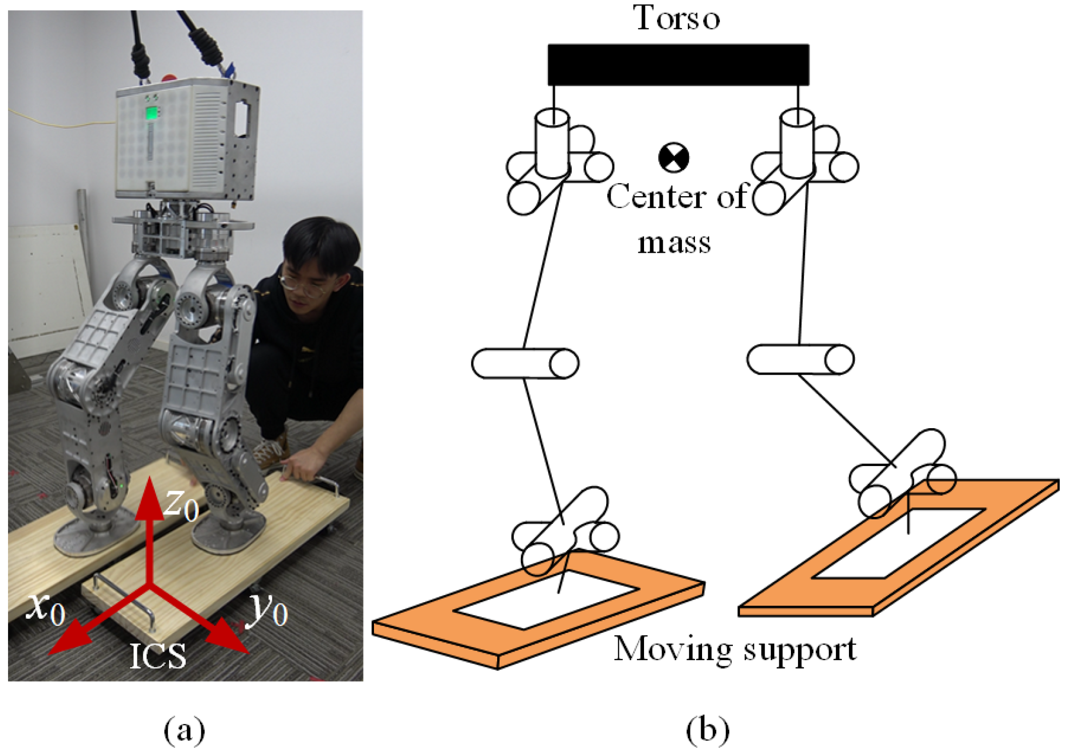
:1. Introduction
2. Control Approach
3. Tasks and Constraints in Dynamic Balancing
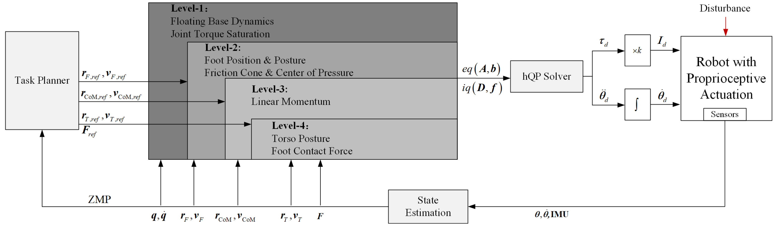
3.1. Task Planner
3.2. Tasks and Constraints Hierarchy
3.2.1. Floating Base Dynamics
3.2.2. Operational Space Tasks
3.2.3. Robot Safety Constraints
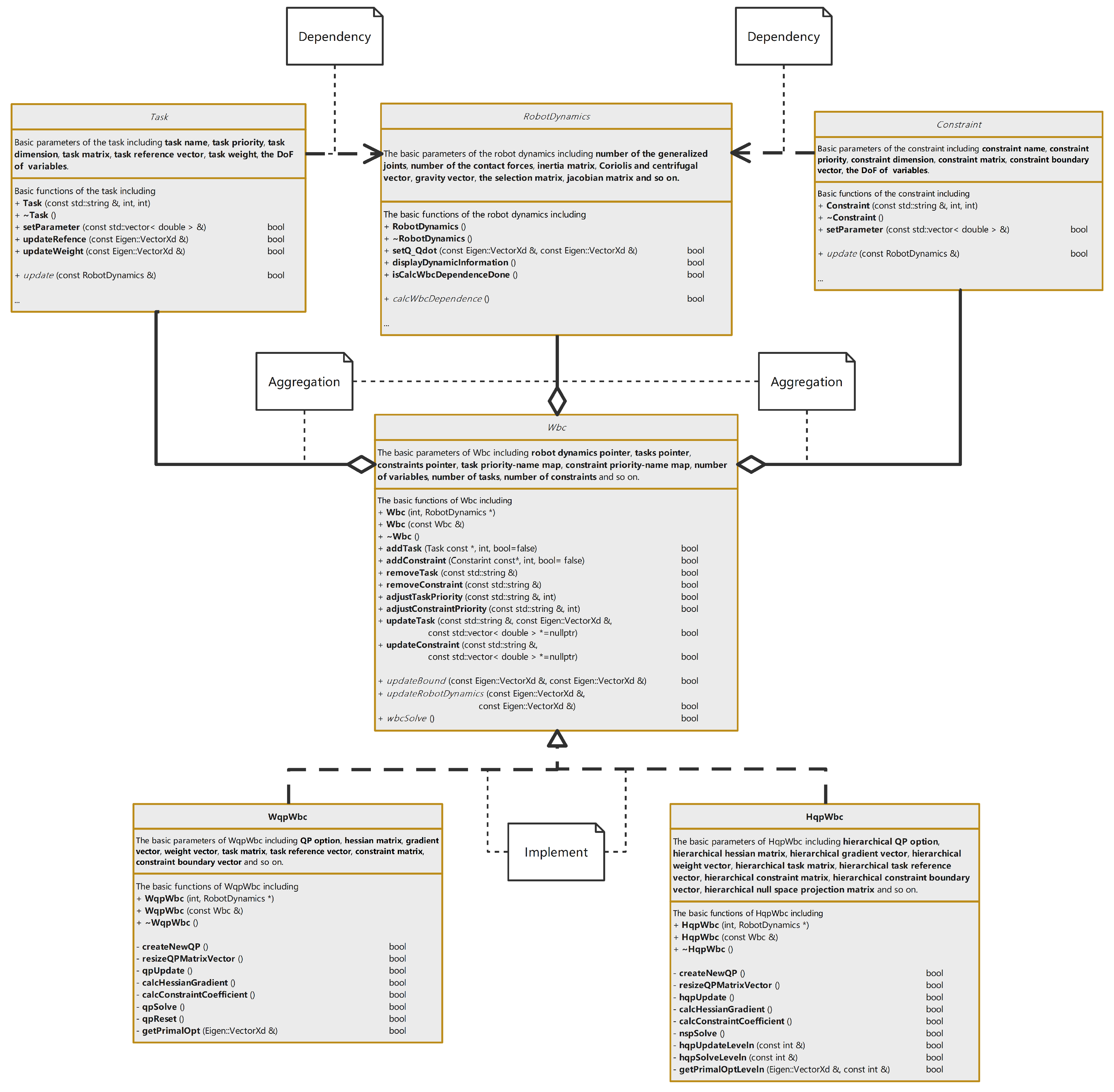
4. Real-Time WBC
4.1. Reduced Hierarchal Whole-Body Control
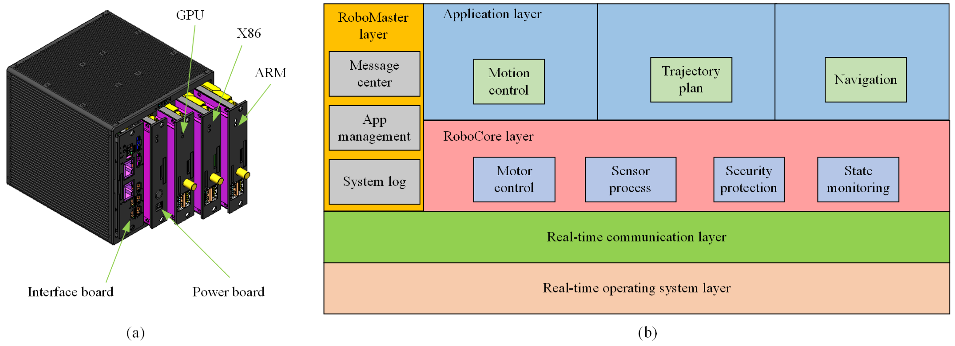
4.2. High-Performance Master Control System
5. Proprioceptive Actuation with a Big Reduction Ratio
5.1. Joint-Level Control
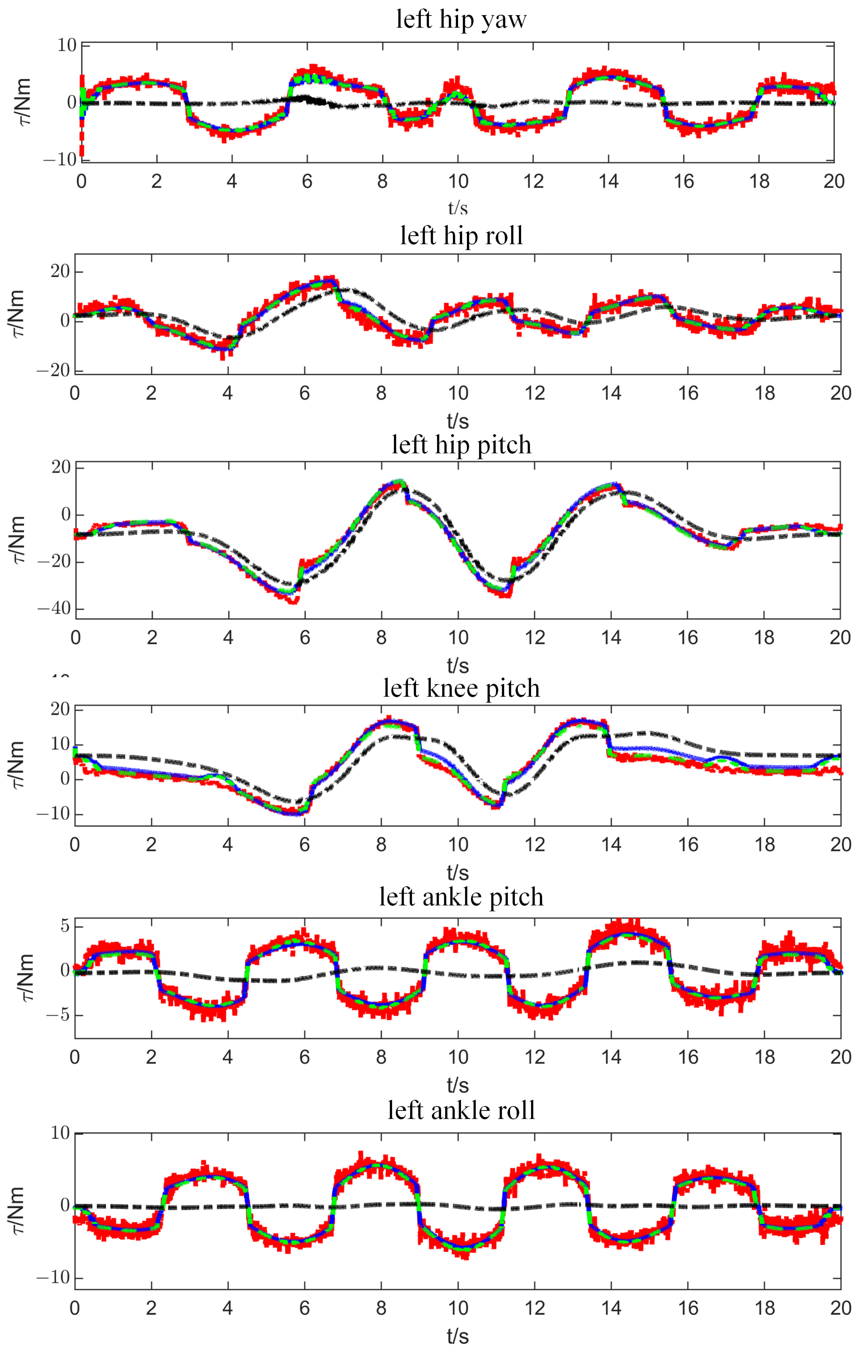
5.2. Model Identification
5.2.1. Linearization of Dynamic Equation
5.2.2. Optimal Excitation Trajectory
5.2.3. Dynamic Parameters Optimization
6. Experimental Results and Discussion
6.1. Push Recovery on the Ground
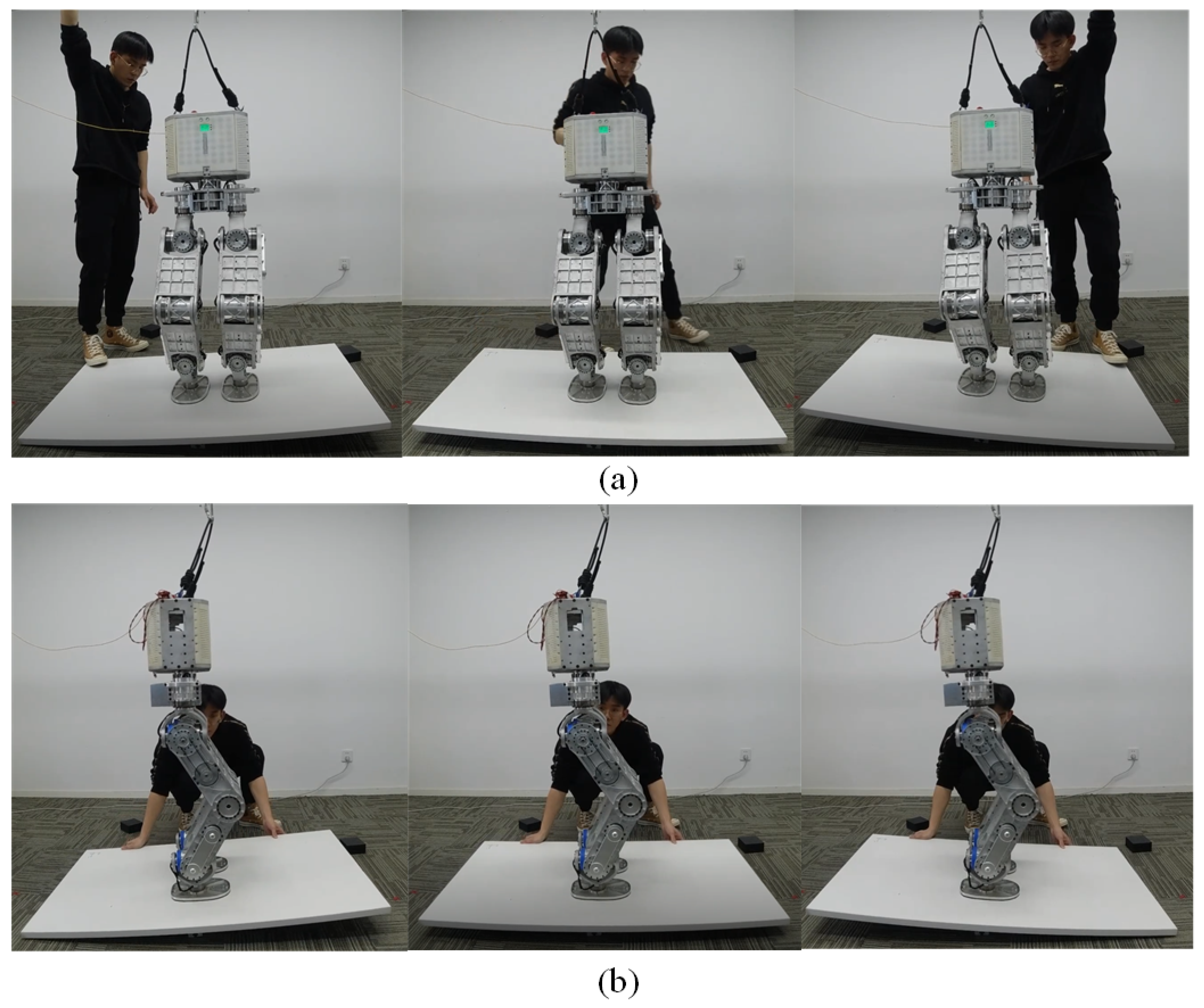
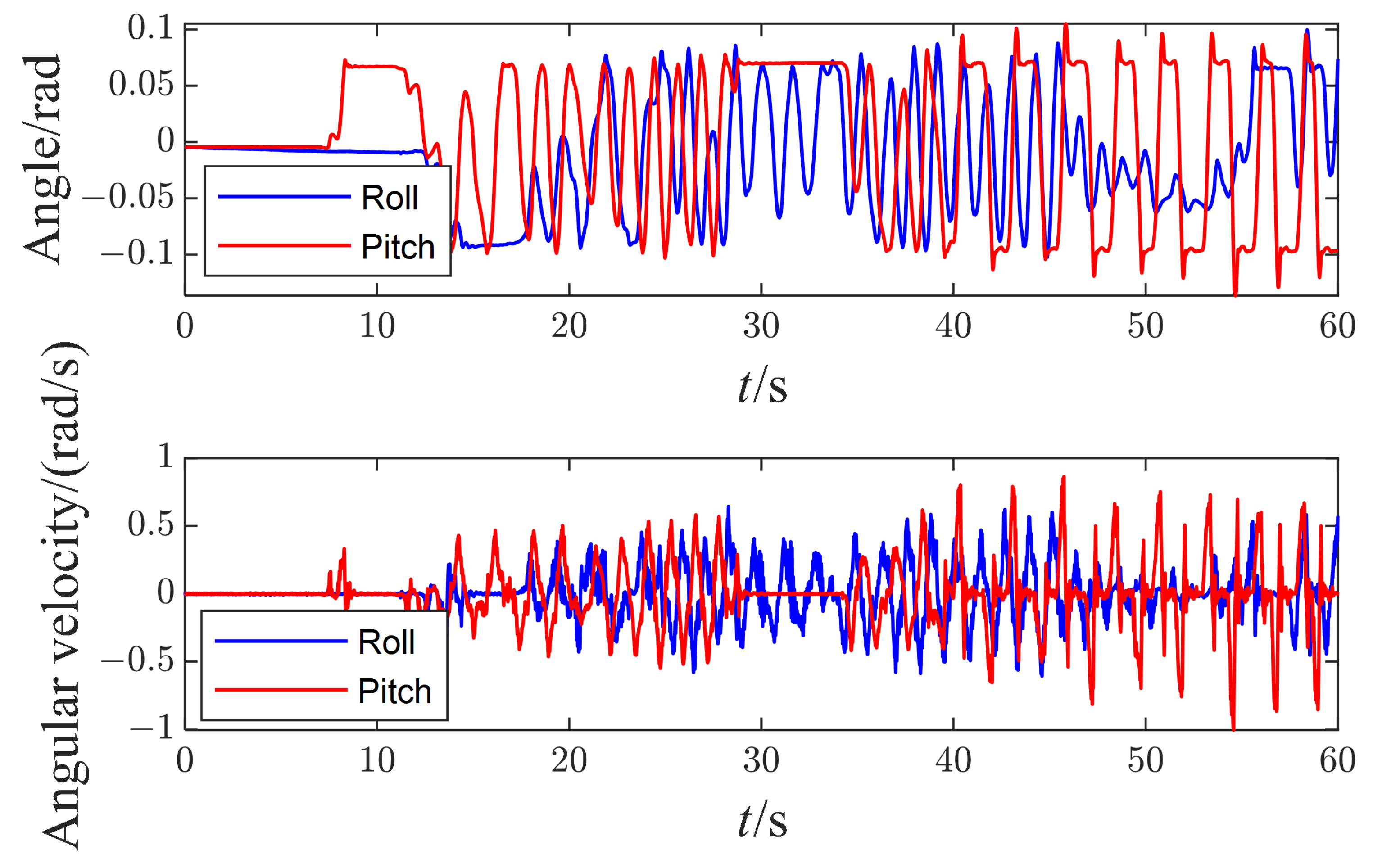
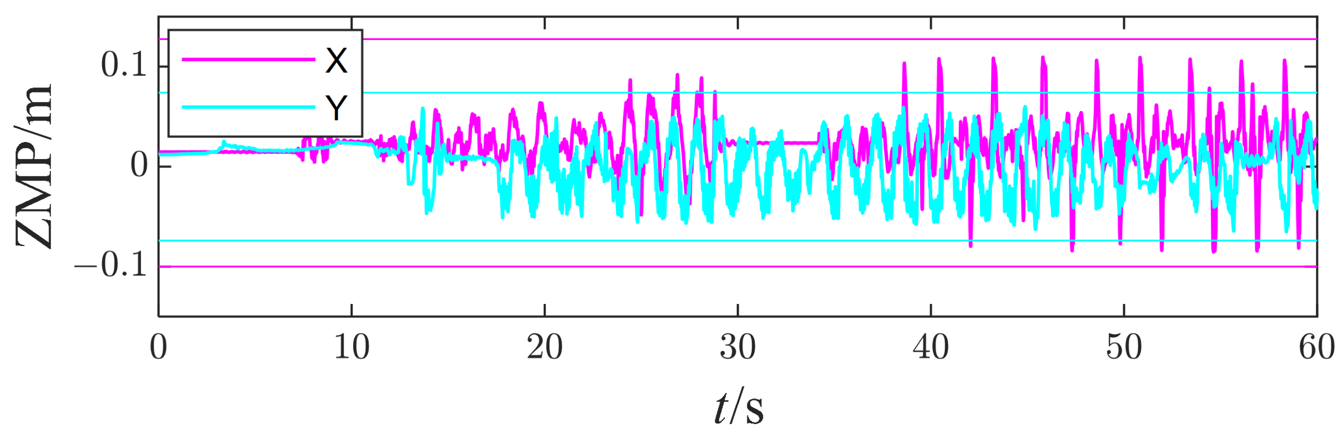
6.2. Balancing on a Seesaw
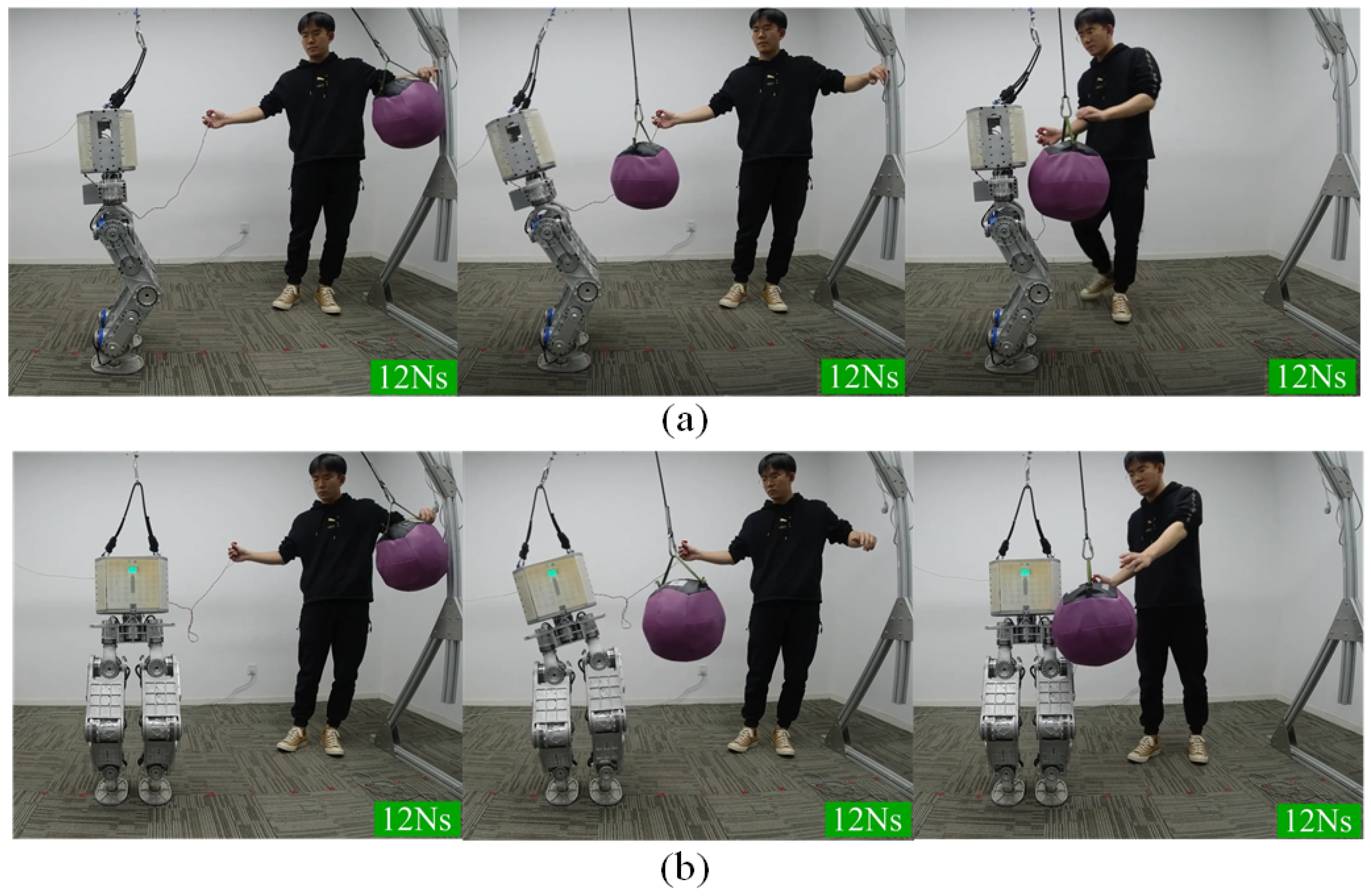
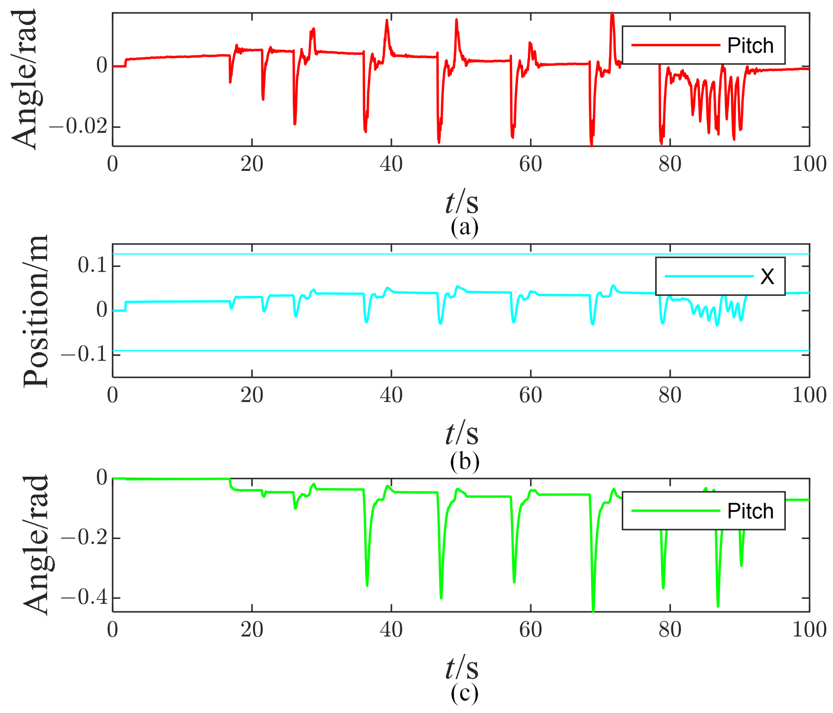
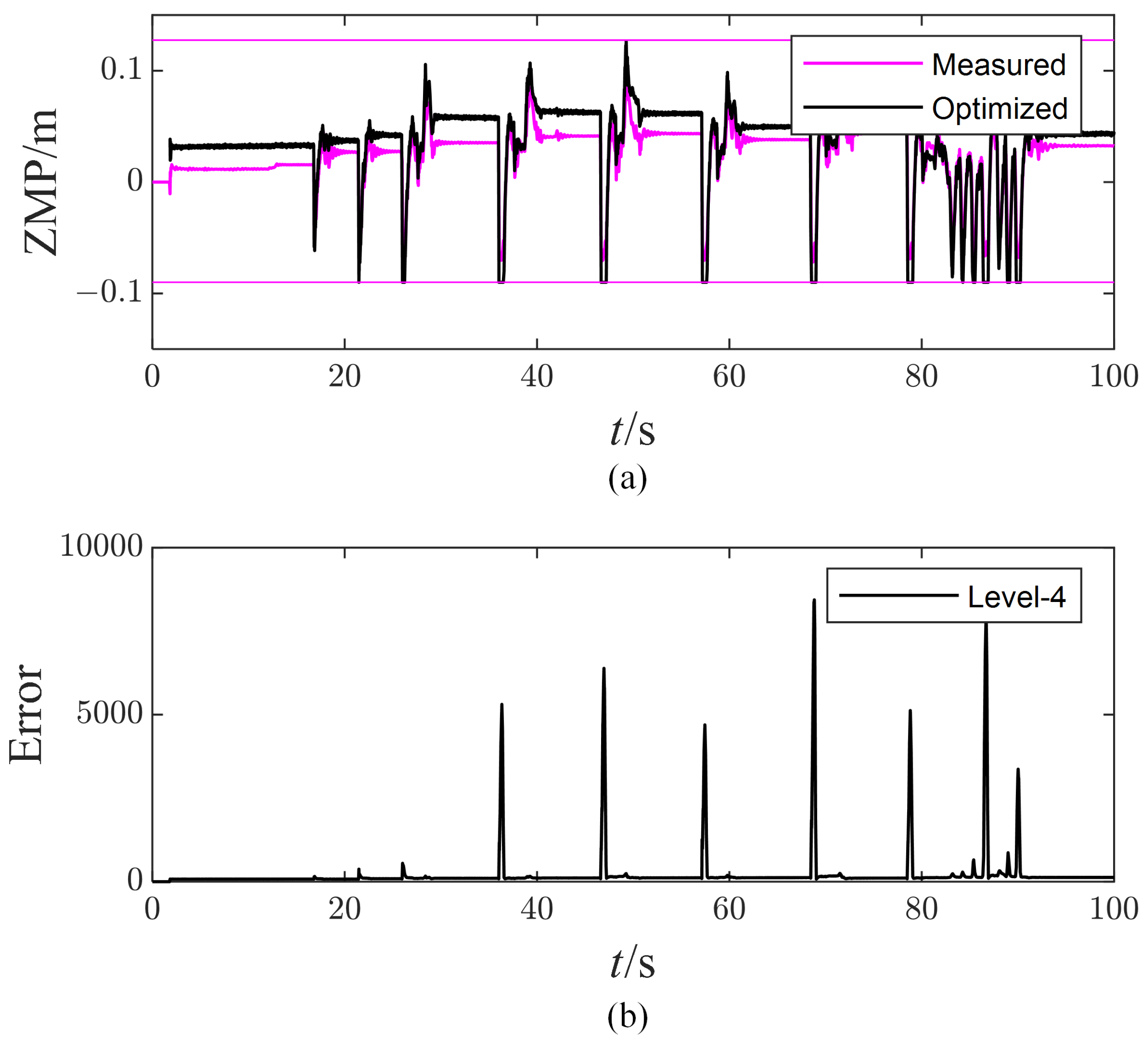
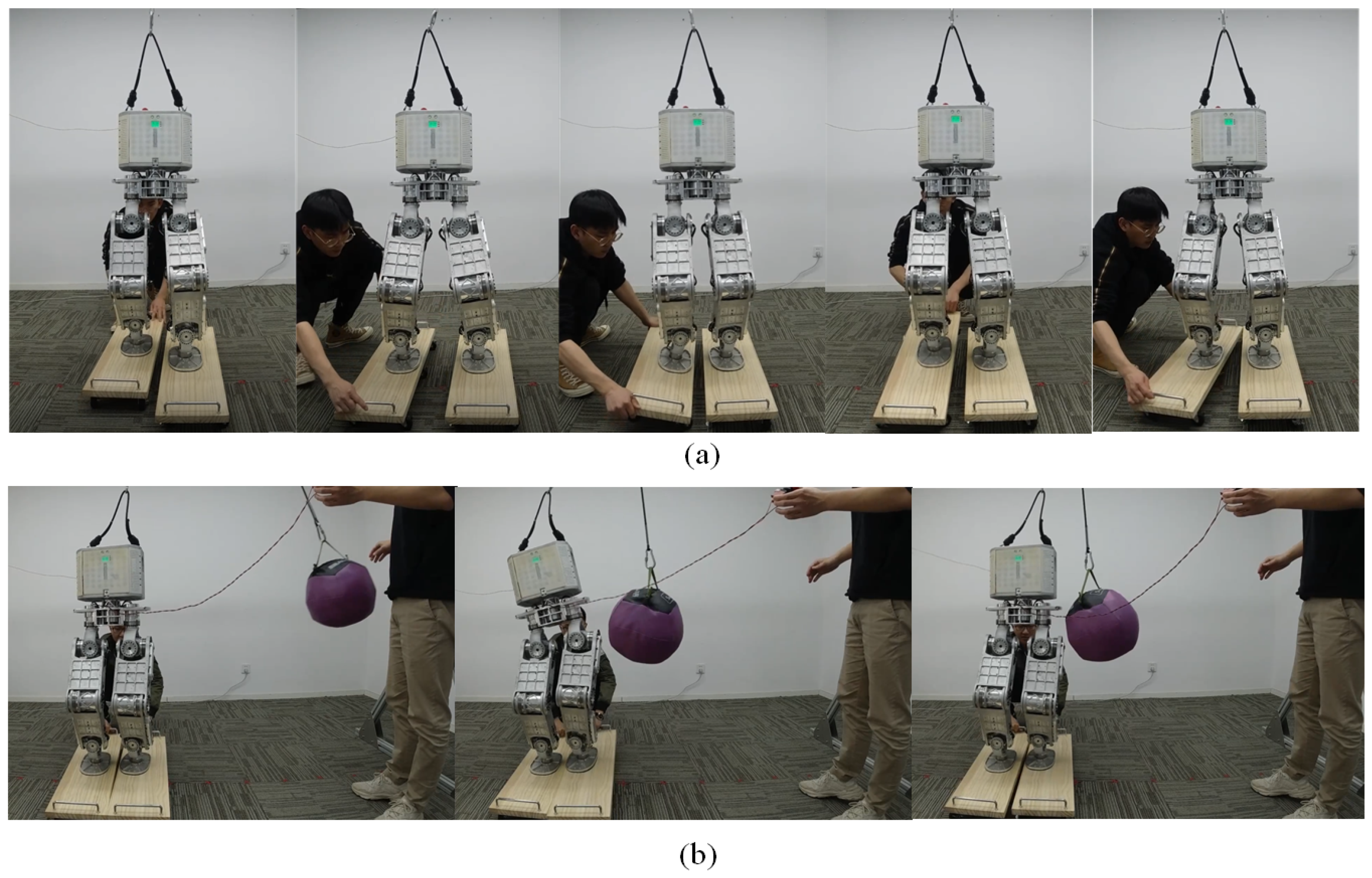
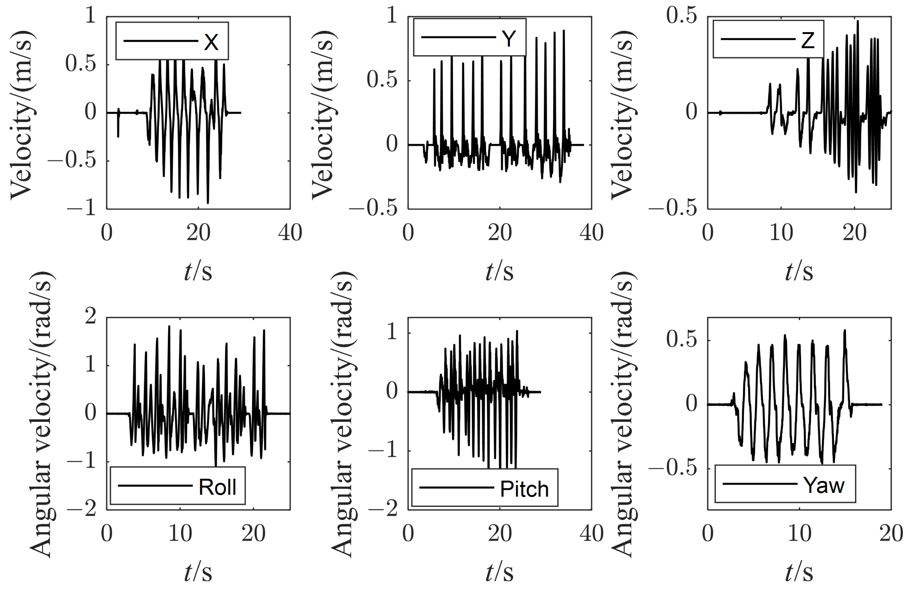
6.3. Push Recovery on Two Moving Skateboards
7. Conclusions
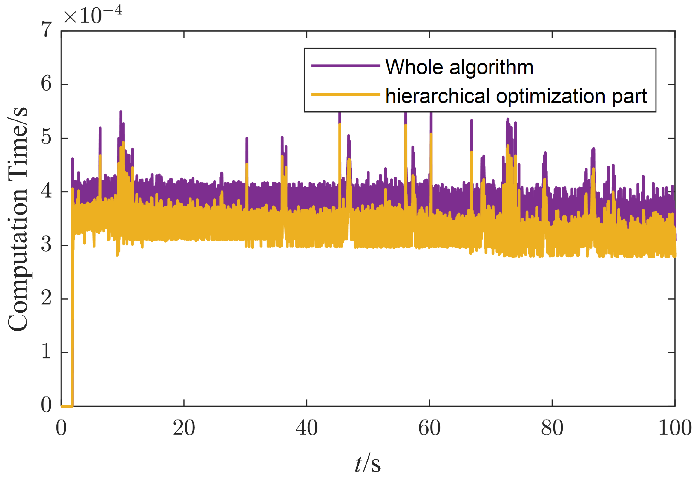
- A real-time computation is achieved through computationally efficient WBC software and a reduced hierarchical whole-body control scheme.
- UBTMaster, a modular control system with real-time communication and powerful computing capabilities, is designed.
- The key dynamic parameters are identified to deal with the nonlinear friction and imprecision of the model of the robot.
Author Contributions
Funding
Data Availability Statement
Conflicts of Interest
References
- Mikolajczyk, T.; Mikołajewska, E.; Al-Shuka, H.F.N.; Malinowski, T.; Kłodowski, A.; Pimenov, D.Y.; Paczkowski, T.; Hu, F.; Giasin, K.; Mikołajewski, D.; et al. Recent Advances in Bipedal Walking Robots: Review of Gait, Drive, Sensors and Control Systems. Sensors 2022, 22, 4440. [Google Scholar] [CrossRef] [PubMed]
- Mikolajczyk, T.; Fas, T.; Malinowski, T.; Romanowski, L. Prototype Model of Walking Robot. Appl. Mech. Mater. 2014, 613, 21–28. [Google Scholar] [CrossRef]
- Ficht, G.; Behnke, S. Bipedal Humanoid Hardware Design: A Technology Review. Curr. Robot. Rep. 2021, 2, 201–210. [Google Scholar] [CrossRef]
- Li, Z.; Zhou, C.; Tsagarakis, N.; Caldwell, D. Compliance control for stabilizing the humanoid on the changing slope based on terrain inclination estimation. Auton. Robot. 2016, 40, 955–971. [Google Scholar] [CrossRef]
- Nenchev, D.N. Reaction null space of a multibody system with applications in robotics. Mech. Sci. 2013, 4, 97–112. [Google Scholar] [CrossRef]
- Dietrich, A.; Ott, C.; Albu-Schäffer, A. An overview of null space projections for redundant, torque-controlled robots. Int. J. Robot. Res. 2015, 34, 1385–1400. [Google Scholar] [CrossRef]
- Nakamura, Y.; Hanafusa, H.; Yoshikawa, T. Task-priority based redundancy control of robot manipulators. Int. J. Robot. Res. 1987, 6, 3–15. [Google Scholar] [CrossRef]
- Kajita, S.; Kanehiro, F.; Kaneko, K.; Fujiwara, K.; Harada, K.; Yokoi, K.; Hirukawa, H. Resolved momentum control: Humanoid motion planning based on the linear and angular momentum. In Proceedings of the 2003 IEEE/RSJ International Conference on Intelligent Robots and Systems (IROS 2003) (Cat. No. 03CH37453), Las Vegas, NV, USA, 27–31 October 2003; Volume 2, pp. 1644–1650. [Google Scholar]
- Dai, H.; Valenzuela, A.; Tedrake, R. Whole-body motion planning with centroidal dynamics and full kinematics. In Proceedings of the 2014 IEEE-RAS International Conference on Humanoid Robots, Madrid, Spain, 18–20 November 2014; pp. 295–302. [Google Scholar] [CrossRef]
- Feng, S.; Whitman, E.; Xinjilefu, X.; Atkeson, C.G. Optimization-based full body control for the darpa robotics challenge. J. Field Robot. 2015, 32, 293–312. [Google Scholar] [CrossRef]
- Koolen, T.; Bertrand, S.; Thomas, G.; de Boer, T.; Wu, T.; Smith, J.; Englsberger, J.; Pratt, J. Design of a Momentum-Based Control Framework and Application to the Humanoid Robot Atlas. Int. J. Hum. Robot. 2016, 13, 1650007. [Google Scholar] [CrossRef]
- De Lasa, M.; Mordatch, I.; Hertzmann, A. Feature-based locomotion controllers. ACM Trans. Graph. TOG 2010, 29, 1–10. [Google Scholar] [CrossRef]
- Kanoun, O.; Lamiraux, F.; Wieber, P.B. Kinematic control of redundant manipulators: Generalizing the task-priority framework to inequality task. IEEE Trans. Robot. 2011, 27, 785–792. [Google Scholar] [CrossRef]
- Escande, A.; Mansard, N.; Wieber, P.B. Hierarchical quadratic programming: Fast online humanoid-robot motion generation. Int. J. Robot. Res. 2014, 33, 1006–1028. [Google Scholar] [CrossRef]
- Herzog, A.; Rotella, N.; Mason, S.; Grimminger, F.; Schaal, S.; Righetti, L. Momentum control with hierarchical inverse dynamics on a torque-controlled humanoid. Auton. Robot. 2016, 40, 473–491. [Google Scholar] [CrossRef]
- Bellicoso, C.D.; Gehring, C.; Hwangbo, J.; Fankhauser, P.; Hutter, M. Perception-less terrain adaptation through whole body control and hierarchical optimization. In Proceedings of the 2016 IEEE-RAS 16th International Conference on Humanoid Robots (Humanoids), Cancun, Mexico, 15–17 November 2016; pp. 558–564. [Google Scholar]
- Wensing, P.M.; Wang, A.; Seok, S.; Otten, D.; Lang, J.; Kim, S. Proprioceptive Actuator Design in the MIT Cheetah: Impact Mitigation and High-Bandwidth Physical Interaction for Dynamic Legged Robots. IEEE Trans. Robot. 2017, 33, 509–522. [Google Scholar] [CrossRef]
- Kim, D.; Zhao, Y.; Thomas, G.; Fernandez, B.R.; Sentis, L. Stabilizing Series-Elastic Point-Foot Bipeds Using Whole-Body Operational Space Control. IEEE Trans. Robot. 2016, 32, 1362–1379. [Google Scholar] [CrossRef]
- Lee, S.H.; Goswami, A. A momentum-based balance controller for humanoid robots on non-level and non-stationary ground. Auton. Robot. 2012, 33, 399–414. [Google Scholar] [CrossRef]
- Wensing, P.M.; Orin, D.E. Improved computation of the humanoid centroidal dynamics and application for whole-body control. Int. J. Hum. Robot. 2016, 13, 1550039. [Google Scholar] [CrossRef]
- Featherstone, R. Rigid Body Dynamics Algorithms; Springer: Berlin/Heidelberg, Germany, 2014. [Google Scholar]
- Dietrich, A.; Wimbock, T.; Albu-Schaffer, A.; Hirzinger, G. Reactive Whole-Body Control: Dynamic Mobile Manipulation Using a Large Number of Actuated Degrees of Freedom. IEEE Robot. Autom. Mag. 2012, 19, 20–33. [Google Scholar] [CrossRef]
- Gaz, C.; Magrini, E.; De Luca, A. A model-based residual approach for human-robot collaboration during manual polishing operations. Mechatronics 2018, 55, 234–247. [Google Scholar] [CrossRef] [Green Version]
- Siciliano, B.; Khatib, O. Springer Handbook of Robotics; Springer: Berlin/Heidelberg, Germany, 2016. [Google Scholar]
- Ferreau, H.J.; Kirches, C.; Potschka, A.; Bock, H.G.; Diehl, M. qpOASES: A parametric active-set algorithm for quadratic programming. Math. Program. Comput. 2014, 6, 327–363. [Google Scholar] [CrossRef]
- Li, Z.; Tsagarakis, N.G.; Caldwell, D.G. Stabilizing humanoids on slopes using terrain inclination estimation. In Proceedings of the 2013 IEEE/RSJ International Conference on Intelligent Robots and Systems, Tokyo, Japan, 3–7 November 2013; pp. 4124–4129. [Google Scholar]


| Level | Task | Task Dimensions | Constraint | Constraint Dimensions |
|---|---|---|---|---|
| 1 | Floating base dynamics | 6 | Joint torque saturation | 12 |
| 2 | Foot position and posture | 12 | Center of pressure and Friction cone | 18 |
| 3 | Linear momentum | 3 | ||
| 4 | Torso posture and Foot contact force | 15 |
| Index | 1 | 2 | 3 | 4∼8 |
|---|---|---|---|---|
| Magnitude | 8 Ns | 10 Ns | 11 Ns | 12 Ns |
Publisher’s Note: MDPI stays neutral with regard to jurisdictional claims in published maps and institutional affiliations. |
© 2022 by the authors. Licensee MDPI, Basel, Switzerland. This article is an open access article distributed under the terms and conditions of the Creative Commons Attribution (CC BY) license (https://creativecommons.org/licenses/by/4.0/).
Share and Cite
Xie, Y.; Wang, J.; Dong, H.; Ren, X.; Huang, L.; Zhao, M. Dynamic Balancing of Humanoid Robot with Proprioceptive Actuation: Systematic Design of Algorithm, Software, and Hardware. Micromachines 2022, 13, 1458. https://doi.org/10.3390/mi13091458
Xie Y, Wang J, Dong H, Ren X, Huang L, Zhao M. Dynamic Balancing of Humanoid Robot with Proprioceptive Actuation: Systematic Design of Algorithm, Software, and Hardware. Micromachines. 2022; 13(9):1458. https://doi.org/10.3390/mi13091458
Chicago/Turabian StyleXie, Yan, Jiajun Wang, Hao Dong, Xiaoyu Ren, Liqun Huang, and Mingguo Zhao. 2022. "Dynamic Balancing of Humanoid Robot with Proprioceptive Actuation: Systematic Design of Algorithm, Software, and Hardware" Micromachines 13, no. 9: 1458. https://doi.org/10.3390/mi13091458