
Surface Acoustic Wave DMMP Gas Sensor with a Porous Graphene/PVDF Molecularly Imprinted Sensing Membrane
by
 ,
,
Sheng Xu
1 ,
,
Rui Zhang
1,2,
Junpeng Cui
1,
Tao Liu
1,
Xiuli Sui
1,
Meng Han
3,
Fu Zheng
4 and
Xiaoguang Hu
1,* 1
School of Software and Communication, Tianjin Sino-German University of Applied Sciences, Tianjin 300350, China
2
School of Electrical and Information Engineering, Tianjin University, Tianjin 300072, China
3
Deepinfar Ocean Technology Co., Ltd., Building #28, Tianjin Binhai Innovation Park, Tianjin 300000, China
4
Tianjin Key Laboratory of Film Electronic and Communicate Devices, School of Electrical and Electronic Engineering, Tianjin University of Technology, Tianjin 300384, China
*
Author to whom correspondence should be addressed.
Micromachines 2021, 12(5), 552; https://doi.org/10.3390/mi12050552
Submission received: 15 April 2021
/
Revised: 5 May 2021
/
Accepted: 10 May 2021
/
Published: 12 May 2021
(This article belongs to the Special Issue Micromachined Gas Sensors)
Abstract
:In this paper, surface acoustic wave (SAW) sensors containing porous graphene/PVDF (polyvinylidene fluoride) molecularly imprinted sensitive membrane for DMMP gas detection were investigated. A 433 MHz ST-cut quartz SAW resonator was used to convert gas concentration changes into frequency shifts by the sensors. The porous graphene/PVDF film was fabricated on the sensor’s surface by using the tape-casting method. DMMP molecules were adsorbed on the porous structure sensing film prepared by the 2-step method to achieve the specific recognition effect. The sensitivity of the sensor could reach −1.407 kHz·ppm−1. The response time and recovery time of the SAW sensor with porous graphene/PVDF sensing membrane were about 4.5 s and 5.8 s at the concentration of 10 ppm, respectively. The sensor has good anti-interference ability to most gases in the air.
1. Introduction
Chemical warfare agents (CWAs) [1] are fast-acting lethal compounds even at low concentration levels. It is necessary to develop CWAs detection technology with high sensitivity, good selectivity, strong anti-interference ability, fast response and compatibility with the current Internet of things technology. Nerve gases [2] are the most dangerous agents of chemical warfare and mass destruction, can cause irreversible damage to the nervous system within seconds and are fatal if exposure occurs for even a few minutes. Therefore, it is very dangerous for researchers to directly study such gases’ sensing characteristics in the laboratory. Almost all studies examine simulants, which have no toxicity or less toxicity, but similar functional groups, structures and properties as nerve gases. DMMP [3,4] is a well-known nerve agent simulator, specifically of Sarin.
As a new and efficient recognition technology, molecularly imprinted technology [5,6] integrates materials science, polymer science, chemical engineering, biochemistry and other disciplines and can recognize specific analytes. Due to the characteristics of predetermination, recognition and practicability, it has been widely used in many fields, such as chromatographic separation [7,8], solid-phase extraction [9,10], biomimetic sensing [11], enzyme catalysis [12], clinical drug analysis [13] and so on. In addition, sensing films prepared by molecularly imprinted technology can also be integrated with electrochemical sensors and microelectronic sensors for detecting trace analytes.
Recently, surface acoustic wave (SAW) sensors [14,15,16] have been extensively used in liquid [17,18] and gas [19,20,21] detection because of their low cost, high precision, miniaturization, and compatibility with semiconductor technology. The SAW sensor consists of a sensing film and a conversion element (SAW resonator or delay line). A sensing film is the core of the SAW sensor. After it adsorbs the analyte to be measured, the SAW converter converts the adsorptions into frequency or phase shifts of the sensor to obtain the device’s response. Due to the high sensitivity and selectivity, the polymer [22,23,24], semiconductor [25,26] and graphene [27,28] sensing films have mostly been used in SAW sensors.
In this paper, we investigated a surface acoustic wave (SAW) sensor with porous PVDF layer sensing film based on molecularly imprinted recognition technology for simulant DMMP detection. A 433 MHz SAW one-port resonator based on ST-quartz substrate and aluminum interdigital transducers (Al-IDTs) was selected to convert the change of gas concentration into frequency shift.
2. Materials and Methods
2.1. Preparation of the SAW Sensor with a Porous Graphene/PVDF Sensing Layer
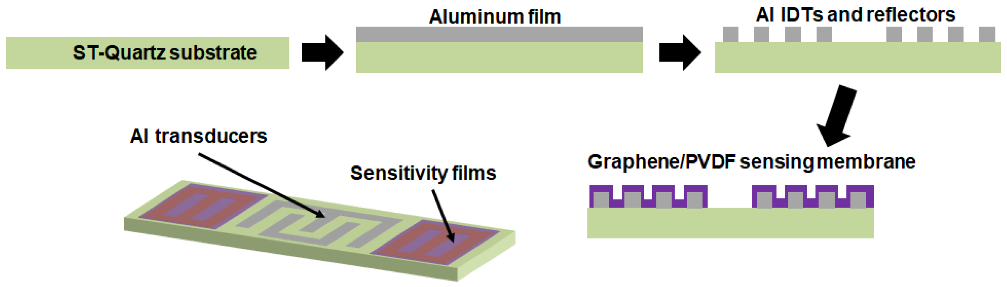
Figure 1 is a schematic diagram of the fabrication process for the one-port SAW resonator as a based device. The substrate was ST-quartz with a SAW velocity of 3158 m·s−1. The aluminum IDTs were fabricated using a standard UV-photolithography process. Each resonator consisted of an IDT with 160 pairs of electrodes and two reflectors on both sides of IDTs with 270 electrodes. The pitch and acoustic apertures were 1.8 μm and 172 μm, respectively. Moreover, the resonant frequency of the SAW devices was approximately 434.9 MHz. The sensing films were coated on both reflectors’ IDTs on the SAW resonator to reduce the propagation loss.
The porous graphene/PVDF sensing films were fabricated as the sensing membrane. First, 0.2 mmol of citric acid monohydrate (CAM), 0.02 mL of dimethyl methyl phosphonate (DMMP), 8 mg of graphene and 0.6 g of polyvinylidene fluoride (PVDF) powder was dispersed in 10 mL of N, N-dimethylformamide (DMF) with the assistance of ultrasonic dispersion to form CAM/DMMP/PVDF/graphene/DMF polymeric precursor solution. Then, 1 mL polymeric precursor solution was coated on the SAW resonator to obtain the porous film using a tape-casting method [29], followed by a drying treatment at 85 °C for 30 min in an oven.
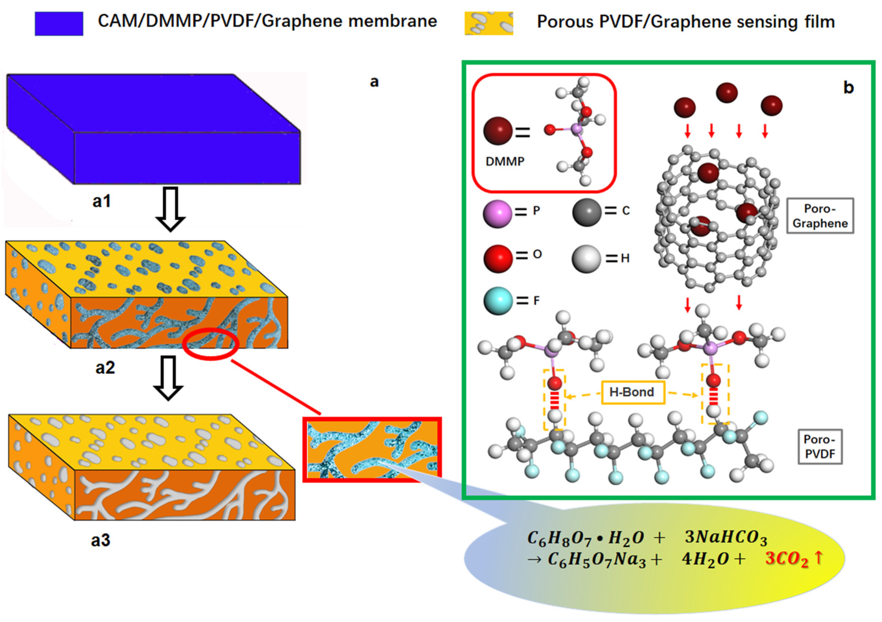
The preparation process of the sensing film on the SAW resonator is shown in Figure 2a. The graphene and recrystallized CAM micro/nanoparticles were uniformly dispersed in the cured graphene/PVDF/DMMP membrane (Figure 2(a1)). Next, the SAW device was immersed in the concentrated NaHCO3 (0.01 mol/L) aqueous solution for 1.5 h at 25 °C. Due to polymer swelling, the CAM nanoparticles near the surface of the sensing film will react with NaHCO3 at the interface between PVDF and graphene. Then, micro holes were formed with the emission of CO2. At the same time, DMMP on the inner wall of the micro-hole and the surface of the film was discharged with CO2 (Figure 2(a2)). Thus, the porous graphene/PVDF sensing films with DMMP molecular imprinting was formed. Finally, the devices were rinsed with ethanol and water to give the SAW sensors (Figure 2(a3)).
2.2. Characterization and Measurement
The morphologies of devices were characterized using scanning electron microscopy (FE-SEM; Merlin Compact, Zeiss, Oberkochen, Germany) and atomic force microscopy (AFM; Agilent 5500, Agilent Technologies, Santa Clara, CA, USA). The crystalline phases of materials were analyzed by X-ray diffraction (XRD; D/max-2500/PC, Rigaku, Tokyo, Japan). The responses of the SAW resonators and sensors were measured by a network analyzer (ENA-E5071C, Keysight, Santa Rosa, CA, USA).
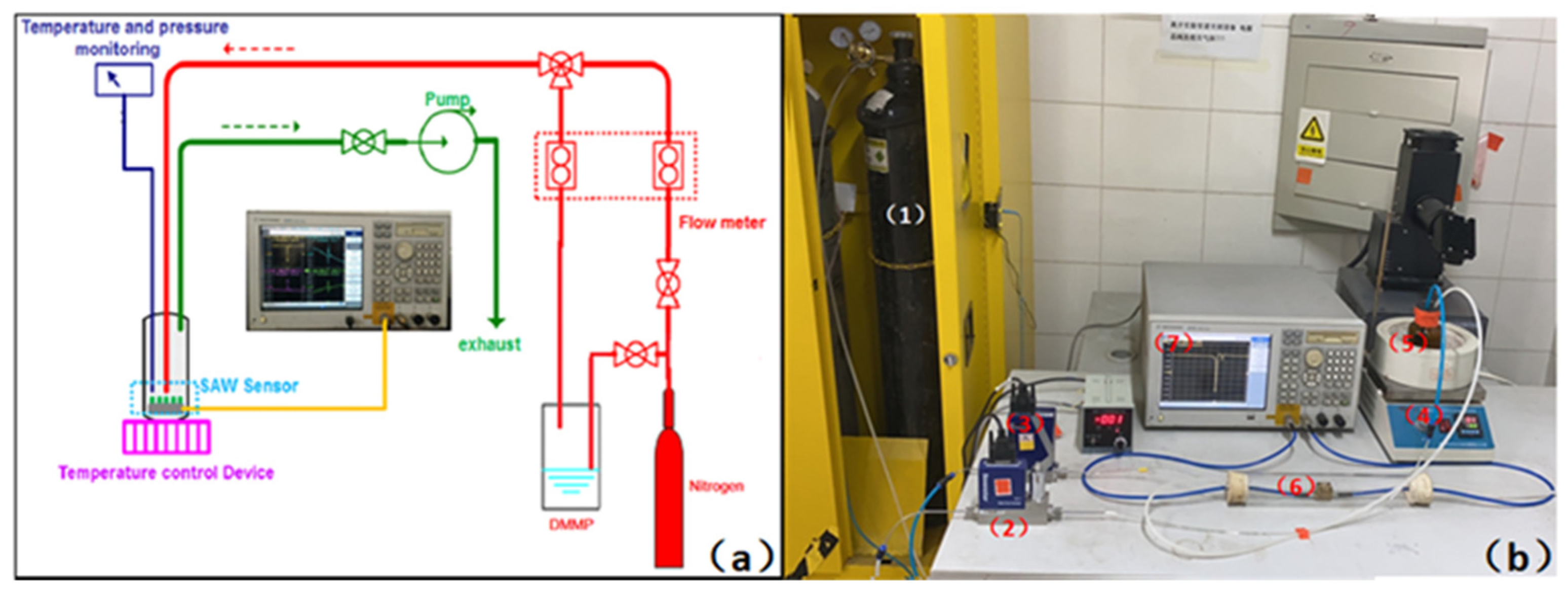
For sensing vapors, a DMMP gas delivery and SAW measurement system was developed as Figure 3, which was included (1) standard N2 source, (2) massflow controller (MFC) for the mixture of N2/ DMMP, (3) MFC for N2, (4) heating device, (5) DMMP source, (6) prepared SAW sensor in a chamber, and (7) network analyzer. The nitrogen from the source was divided into two paths, one carrying the DMMP and the other only carrier to the sensor surface. Both were precisely controlled by MFC. The gas flow rate of the N2/DMMP path was maintained at 250 mL·min−1, and the flow rate of the pure nitrogen path can be adjusted. The flask containing DMMP is heated to 30 °C or 50 °C. Using the molar volume at different temperatures and flow differences between two gas channels, the concentration of the DMMP scan be achieved [30,31]. The SAW sensor was placed in a sealed chamber with a volume of about 500 mL. A pump was connected to the chamber’s outlet to realize the weak negative pressure in the test system, which could ensure the dynamic circulation of gas and the tightness of the system. Before testing, the SAW sensor, fixed on the test fixture, was placed in an N2 environment and preheated to 80 °C for 1 h to remove any gas absorbed on the sensing film.
3. Results and Discussion
3.1. Characterization and Measurement Results
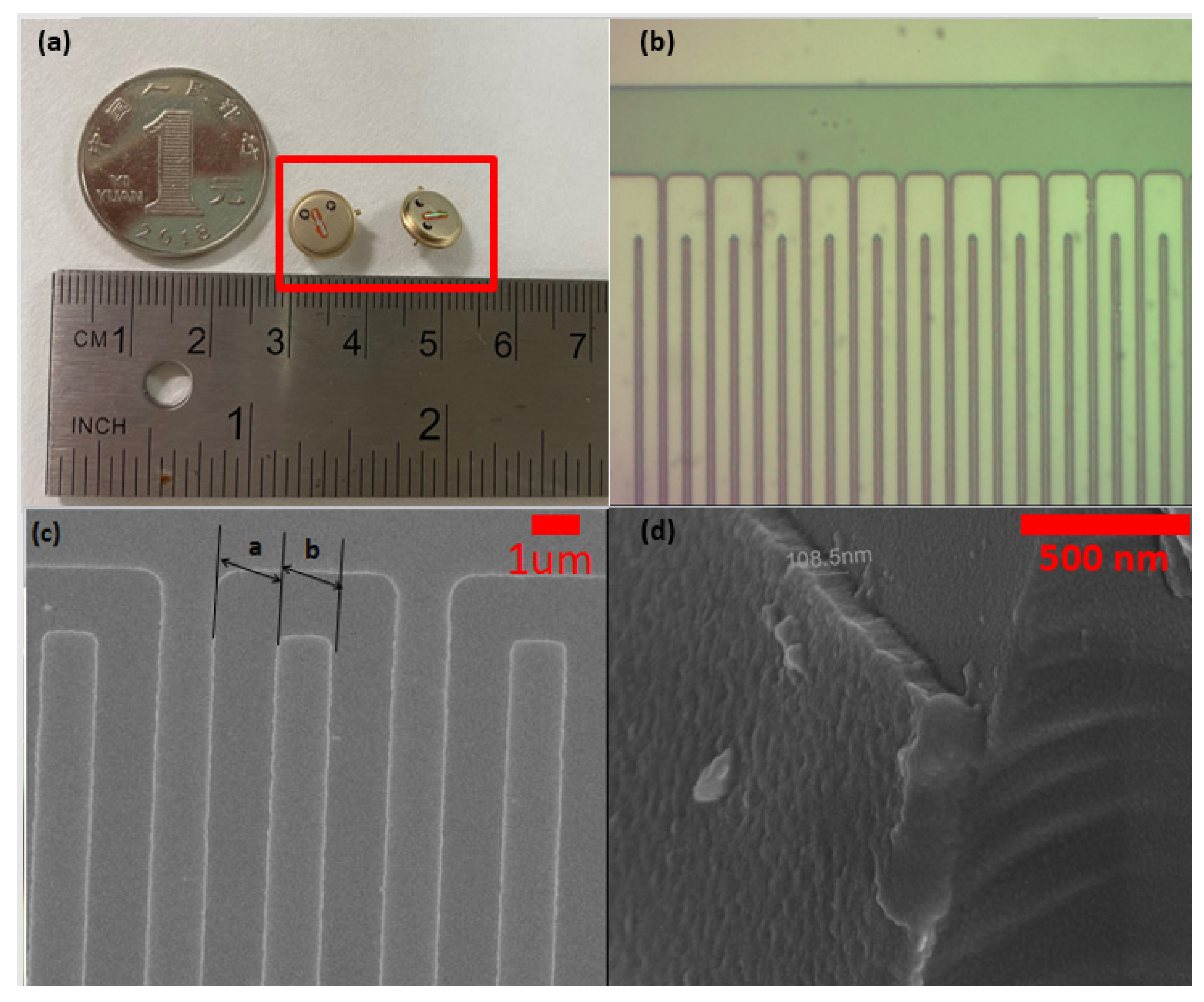
Figure 4a is the image of a one-port SAW resonator fabricated by a standard integrated circuit manufacturing method. Figure 4b,c shows the OM and SEM images of IDTs, which confirm that the IDTs finger width and gap are equal to 1.6 um, respectively. Figure 4d is the cross-sectional SEM images of IDTs, showing that the thickness of aluminum electrodes is about 108.5 nm.
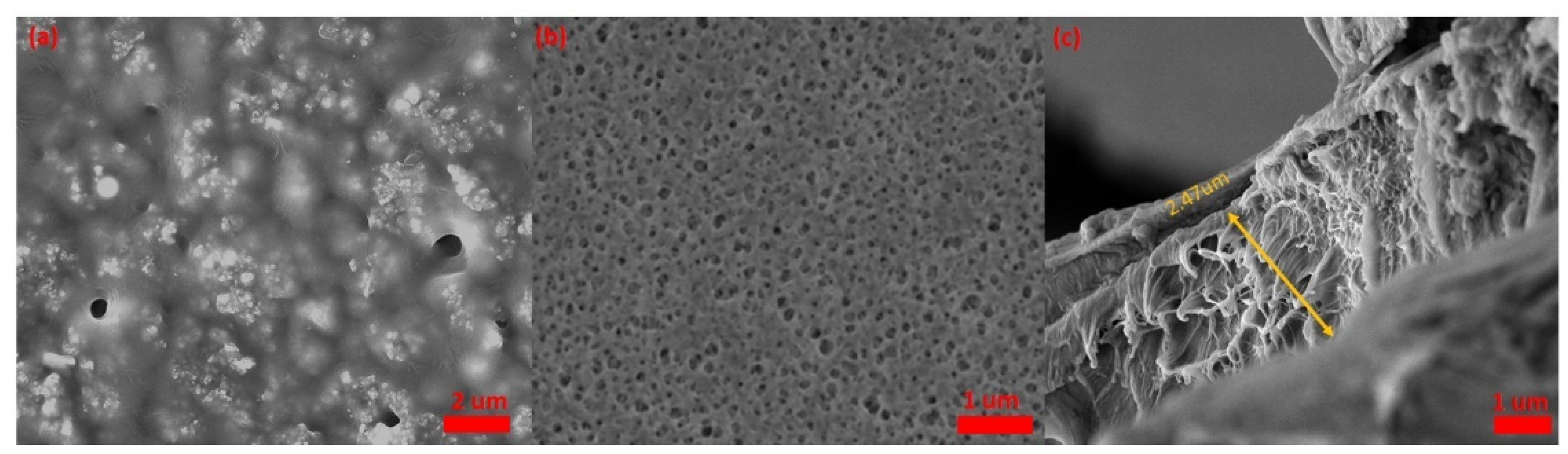
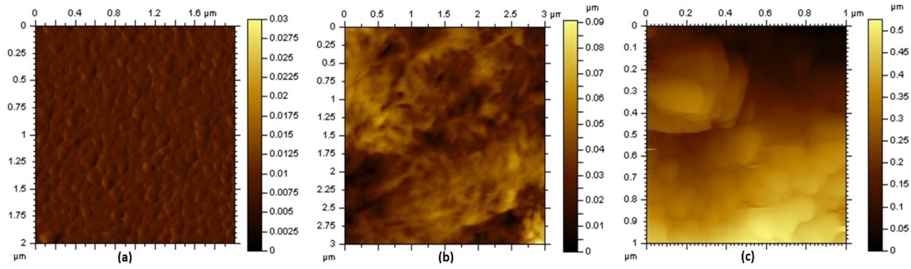
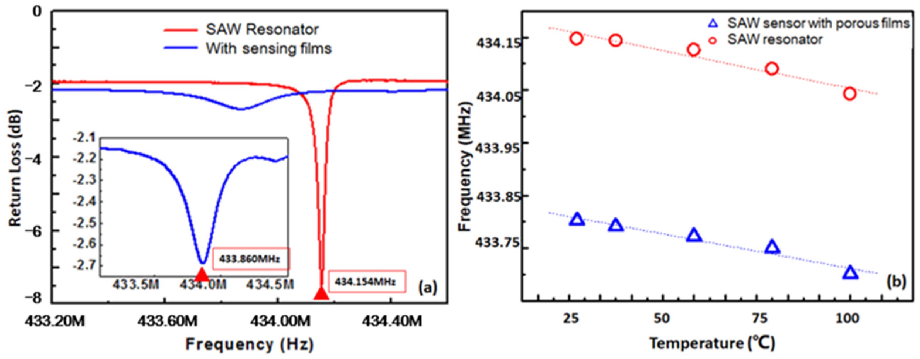
Figure 5a is the SEM images of graphene/PVDF/CAM/DMMP membrane, showing that the graphene and recrystallized CAM micro/nanoparticles were uniformly dispersed in the film. After immersion in the NaHCO3 solution, the recrystallized CAM precipitated in the form of carbon dioxide and formed a porous structure on the surface of the sensing film (Figure 5b). The thickness of the sensing film was about 2.47 μm (Figure 5c). Figure 6 shows AFM images of the Al IDTs, PVDF/DMMP film and porous graphene/PVDF sensing film. The roughness (RMS) of the IDT electrodes on one-port SAW resonator, PVDF/DMMP /SAW, and porous graphene/PVDF /SAW was 1.14 nm, 10.9 nm and 119 nm, respectively. With the formation of the porous structure sensing film, the roughness of the sensor surface increased significantly, which led to the S11 of the device decreasing from −8.21 dB to −2.68 dB (Figure 7a). Moreover, after the sensing film was fabricated on the reflective grating, the resonant frequency of the sensor showed a negative frequency shift of about 294 kHz due to the mass-loading effect [32].
The temperature coefficient of frequency (TCF), which is an important parameter to characterize the temperature stability of the SAW sensor, was observed in the range of 25–100 °C. As shown in Figure 7b, the preparation of the sensing film did not lead to significant changes in the temperature stability of the device. The TCF of the bare SAW resonator and SAW sensor with porous graphene/PVDF sensing membrane was −1.4305 ppm/°C and −1.5624 ppm/°C.
3.2. Static Responses of DMMP Sensors
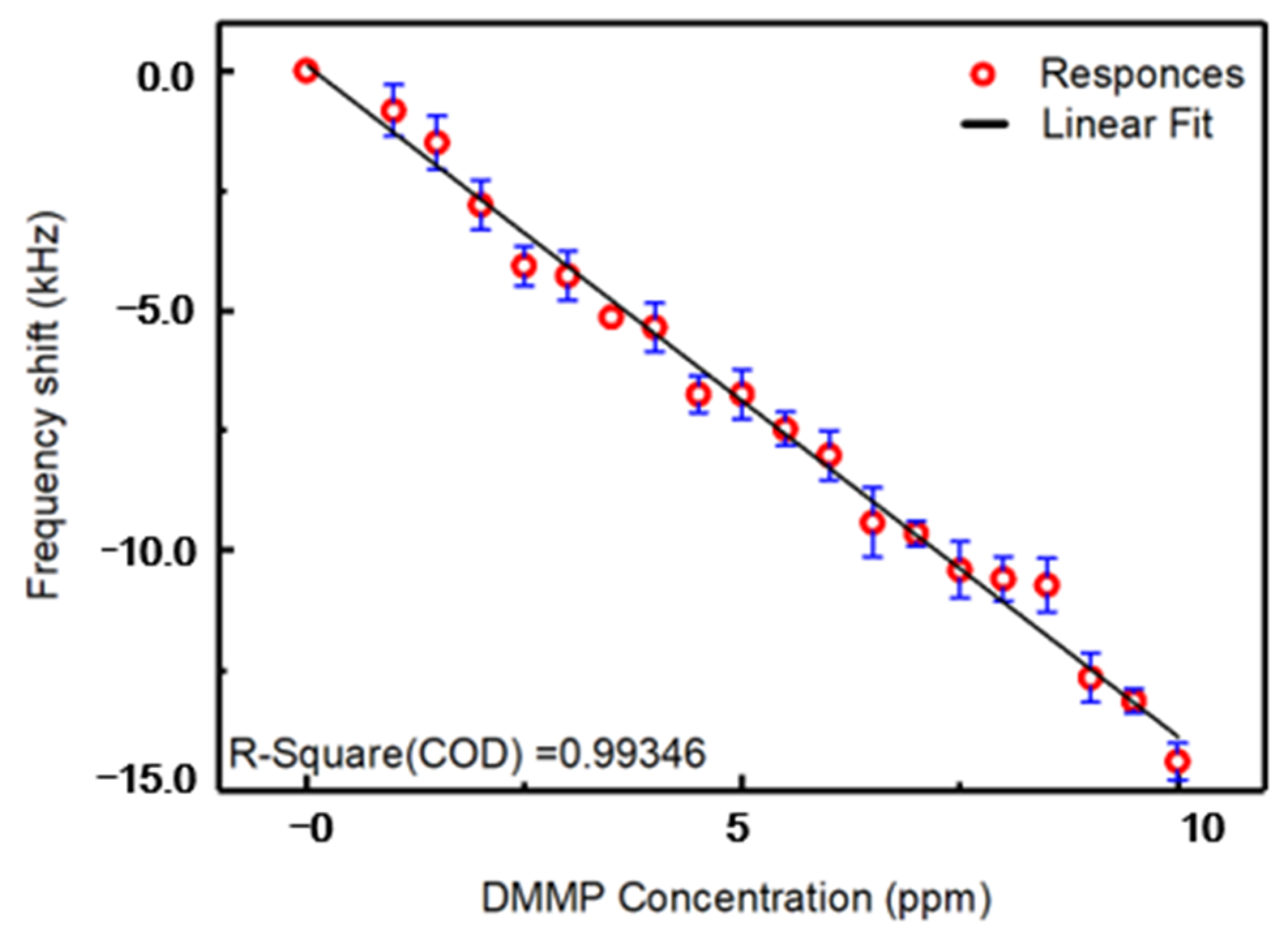
Figure 8 shows the static responses of the SAW gas sensor with different DMMP concentrations in the range from 0 to 10 ppm. The sensor was tested more than 10 times at each concentration value. The raw data, statistical analysis and residual plots are shown in Table S1 and Figure S2. The response of the SAW sensor decreased rapidly with increasing DMMP concentration in the range from 0 to 10 ppm. The sensitivity of the sensor, which can be obtained from the slope of the linear fitting (solid black line in Figure 8), was about −1.407 kHz/ppm (R = 0.99346). The linear-regression equation, parameters, statistics and R-value are shown in Figure S3.
3.3. Dynamic Responses and Sensing Mechanism
The frequency shift of the SAW sensors based on the electric loading effect can be correlated with the sheet conductivity and the surface capacitance per length of the sensing film using the following relationship [33,34]:
where v0 is the effective SAW velocity of the device, K2 is the electromechanical coupling coefficient of the piezoelectric substrate, σS is the sheet conductivity, and CS is the surface capacitance per length. In the process of adsorbing DMMP gas, CS, which is determined by the structure of the device, remains constant. The porous graphene and PVDF film could both absorb DMMP gas and resulted in a decrease of resonant frequency due to the shift of the sheet conductivity. The sheet conductivity of porous graphene/PVDF film was about 6.1 × 10⁻³ S/cm under pure N2 and 2.7 × 10⁻³ S/cm under 10 ppm DMMP gas.
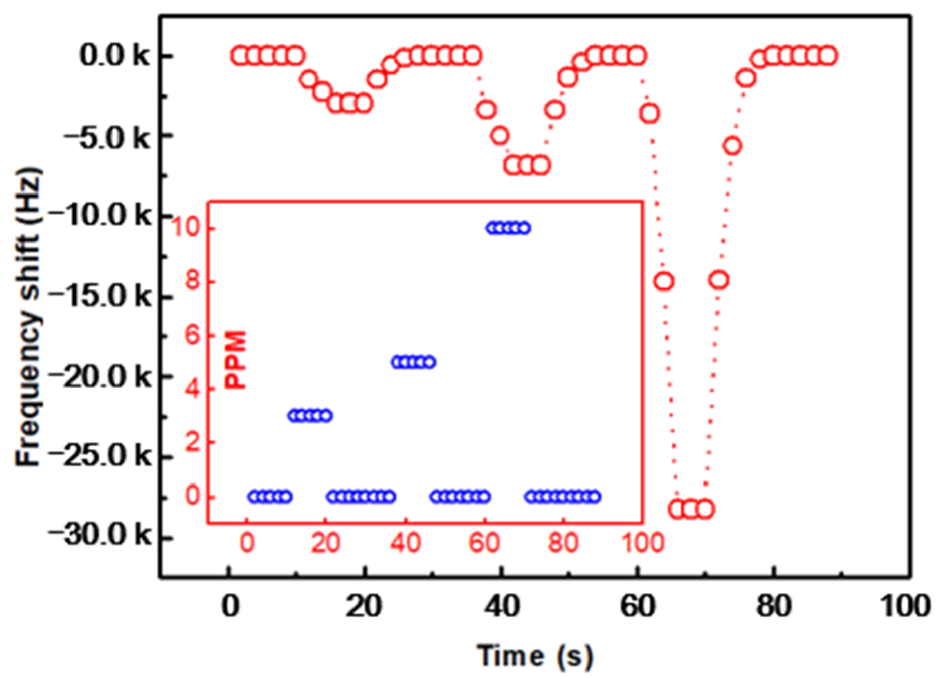
As shown in Figure 9, the dynamic responses of the prepared SAW sensors with porous PVDF sensing film to fast DMMP concentration (0, 3, 5, 10 ppm) changes were investigated. The blue bubble was the DMMP concentration–time curve. The gas concentration was determined by the ratio of nitrogen and DMMP, while 0 ppm is pure nitrogen with equal gas flow. The response time and recovery time were defined as the time required for the frequency shift to achieve 10% and 90% of the change for the adsorption and desorption processed, respectively [35]. It can be seen from Figure 9 that the response time of the sensor was clearly faster than the recovery time. For the concentration of 3 ppm, 5 ppm and 10 ppm, the response time was about 2.9 s, 3.6 s, and 4.5 s, and the recovery time was about 3.7 s, 4.9 s, 5.8 s, respectively. When DMMP gas was introduced into the sensitive membrane, the molecularly imprinted sensitive membrane could quickly capture the analyte. Moreover, the hydrogen bond structure between DMMP and PVDF needs a certain gas flux to desorb when the gas concentration decreased. Figure 2b shows the gas adsorption and hydrogen bond formation diagram. In the multilayer sensing film, PVDF was used to protect the metal interdigital electrode, and porous graphene could effectively increase the specific surface area of the sensing film and increased the adsorption of the gas to be measured. When the sensitive membrane adsorbs DMMP gas, DMMP molecules pass through the porous structure, the O atom in the P = O group of DMMP and the H atom of PVDF form an H-bond [36] structure, which achieves specific recognition. The synergetic effect between PVDF and porous graphene was proven by the enhancement of sensitivity.
3.4. Selectivity and Stability
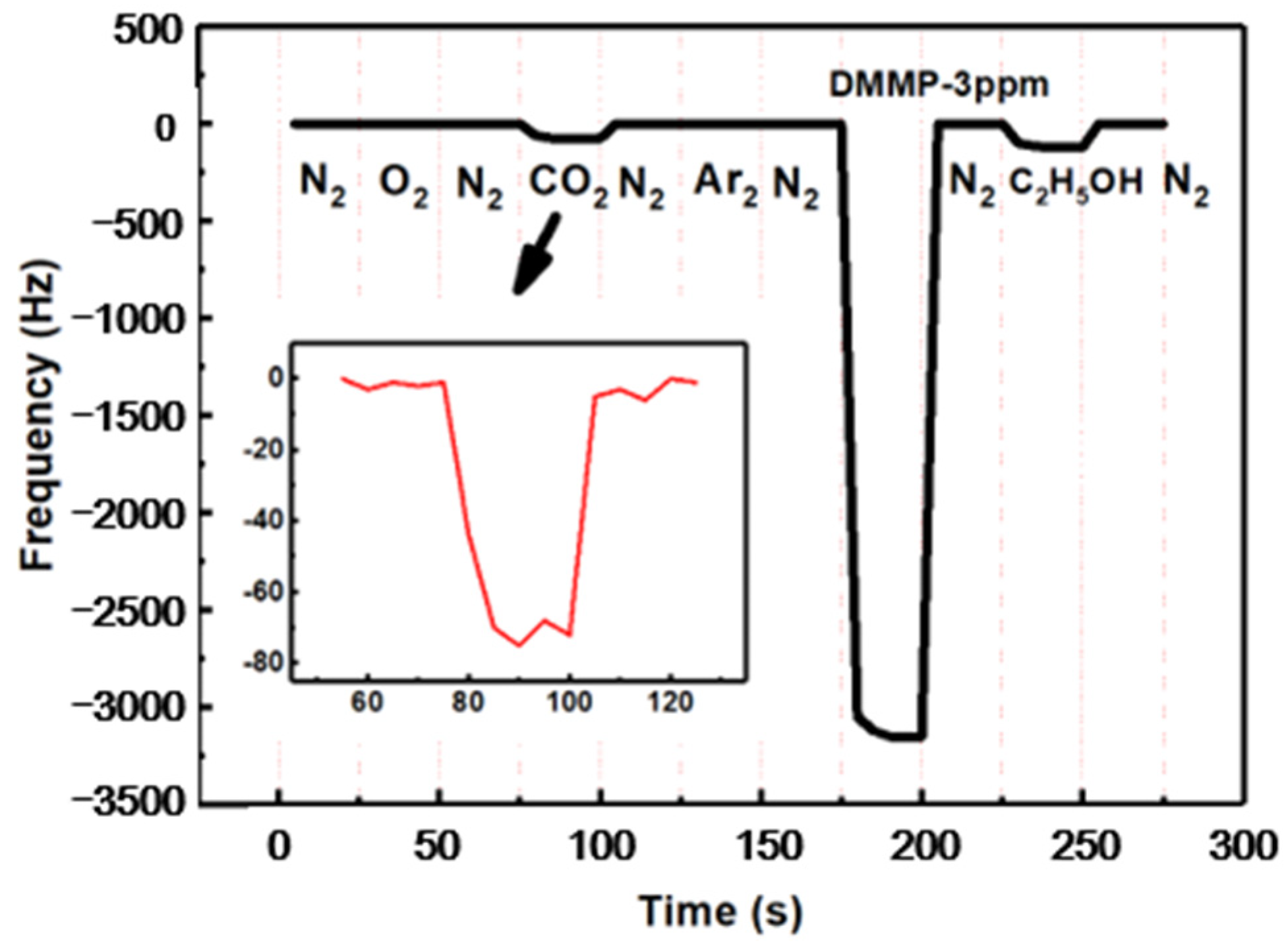
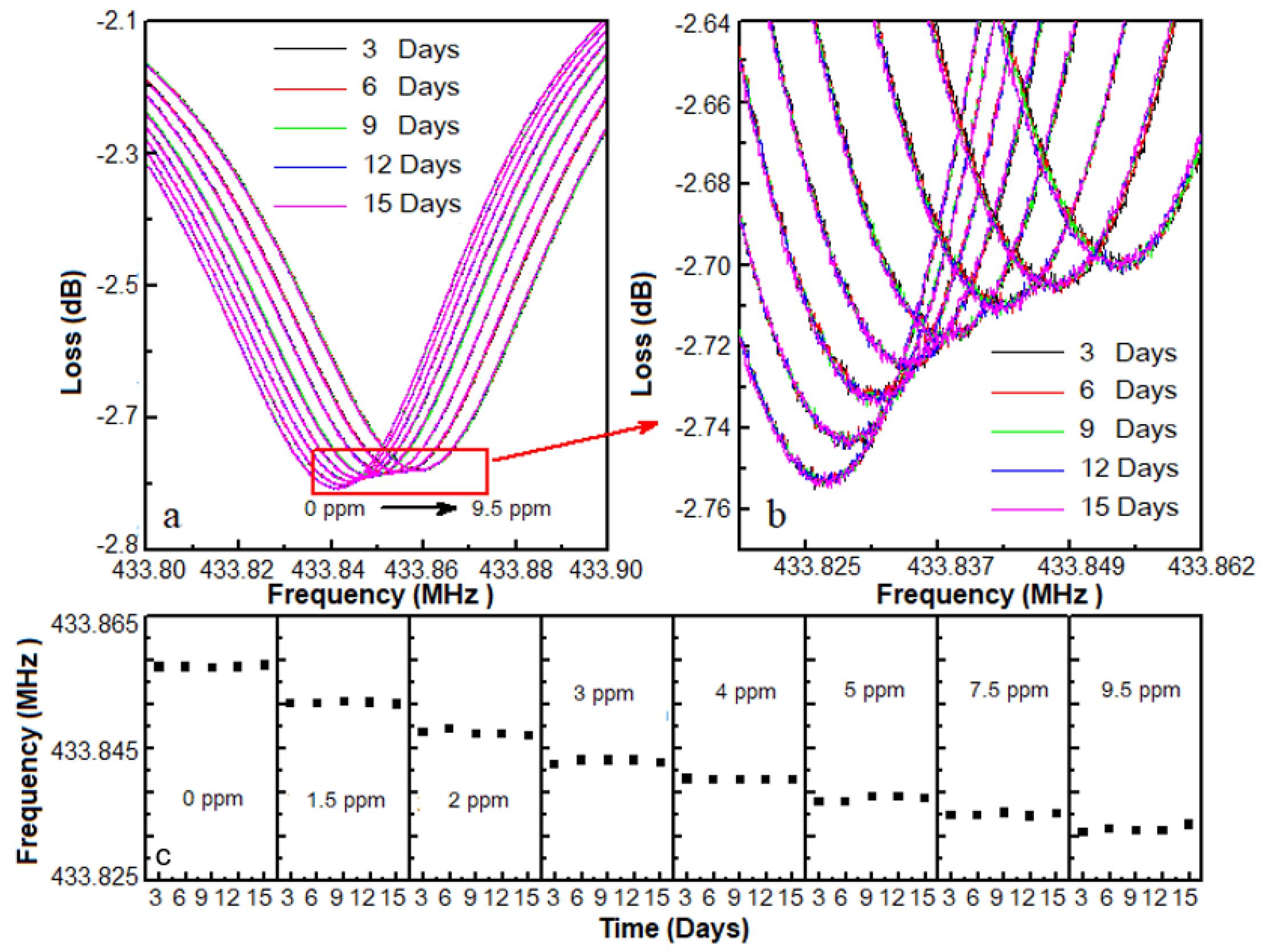
Figure 10 shows the selectivity of the SAW DMMP sensor. The SAW sensor did not have a marked response to pure N2, O2 and Ar. Although the responses could be interfaced by pure CO2 and ethanol gases, it was also far less than DMMP of 3 ppm. These results suggest that due to the preparation of molecularly imprinted sensitive membrane, the sensor had strong selectivity for DMMP. Furthermore, as shown in Figure 11, the response frequencies for different DMMP concentrations were recorded for 15 days to verify the stability of the sensors. When the time of storage increased, the frequency shifts of the porous graphene/PVDF SAW sensor were nearly constant.
4. Conclusions
In this paper, a DMMP gas sensor based on the SAW device with a porous graphene/PVDF molecularly imprinted sensing membrane was developed. The sensing membrane with a porous structure could improve the adsorption capacity of DMMP gas. Due to the molecularly imprinted recognition technology used in the sensing film, the SAW sensor, which had an excellent anti-interference ability, could detect DMMP specifically. The sensitivity of the sensor could reach −1.407 kHz·ppm−1. The response time of the SAW sensor with porous graphene/PVDF molecularly imprinted sensing membrane was faster than 4.5 s, and the recovery time was faster than 5.8 s at the concentration of 10 ppm. Furthermore, the developed SAW sensor could also be used for real-time and online monitoring of nerve gas.
Supplementary Materials
The following are available online at https://www.mdpi.com/article/10.3390/mi12050552/s1, Figure S1: Responses of the bare SAW and sensor with sensitivity film for TCF, Figure S2: Residual plots for the data of Figure 8, Table S1: Statistical Analysis of the Experimental Data.
Author Contributions
Conceptualization, S.X. and R.Z.; methodology, X.H.; software, X.S. and T.L.; validation, S.X. and J.C.; formal analysis, R.Z.; investigation, M.H.; resources, X.H.; data curation, S.X.; writing—original draft preparation, F.Z., S.X. and J.C.; writing—review and editing, S.X. All authors have read and agreed to the published version of the manuscript.
Funding
This research was funded by the Natural Science Foundation of Tianjin, grant number 20JCYBJC00280.
Conflicts of Interest
The authors declare no conflict of interest.
References
- Kloske, M.; Witkiewicz, Z. Novichoks—The A group of organophosphorus chemical warfare agents. Chemosphere 2019, 221, 672–682. [Google Scholar] [CrossRef] [PubMed]
- Zhao, S.; Zhu, Y.; Xi, H.; Han, M.; Li, D.; Li, Y.; Zhao, H. Detoxification of mustard gas, nerve agents and simulants by peroxomolybdate in aqueous H2O2 solution: Reactive oxygen species and mechanisms. J. Environ. Chem. Eng. 2020, 8, 104221. [Google Scholar] [CrossRef]
- Li, Y.; Li, Z.; Guo, L.; Yang, B.; Li, T. Enhanced dual-wavelength upconversion luminescence, thermosensitivity and DMMP detection of multifunctional Gd2MoO6: Er3+/Yb3+ nanoparticles. J. Alloys Compd. 2020, 847, 156399. [Google Scholar] [CrossRef]
- Wu, Y.-L.; Sun, Y.-Q.; Li, X.-X.; Zheng, S.-T. A new dimeric isopolyoxoniobate {β-H4Nb52O150} decorated with copper(II)-ethylenediamine for hydrolytic decomposition of chemical warfare agent simulant DMMP. Inorg. Chem. Commun. 2020, 113, 107815. [Google Scholar] [CrossRef]
- Sroysee, W.; Chunta, S.; Amatatongchai, M.; Lieberzeit, P.A. Molecularly imprinted polymers to detect profenofos and carbofuran selectively with QCM sensors. Phys. Med. 2019, 7, 100016. [Google Scholar] [CrossRef]
- Hassanpour, A.; Irandoust, M.; Soleimani, E.; Zhaleh, H. Increasing the anticancer activity of azidothymidine toward the breast cancer via rational design of magnetic drug carrier based on molecular imprinting technology. Mater. Sci. Eng. C 2019, 103, 109771. [Google Scholar] [CrossRef]
- Zhang, K.; Zhou, T.; Kettisen, K.; Ye, L.; Bülow, L. Chromatographic separation of hemoglobin variants using robust molecularly imprinted polymers. Talanta 2019, 199, 27–31. [Google Scholar] [CrossRef]
- Moein, M.M. Advancements of chiral molecularly imprinted polymers in separation and sensor fields: A review of the last decade. Talanta 2021, 224, 121794. [Google Scholar] [CrossRef]
- Maranata, G.J.; Surya, N.O.; Hasanah, A.N. Optimising factors affecting solid phase extraction performances of molecular imprinted polymer as recent sample preparation technique. Heliyon 2021, 7, e05934. [Google Scholar] [CrossRef]
- Vasconcelos, I.; Da Silva, P.H.R.; Dias, D.R.D.; Marques, M.B.D.F.; Mussel, W.D.N.; Pedrosa, T.A.; E Silva, M.E.S.R.; Freitas, R.F.D.S.; De Sousa, R.G.; Fernandes, C. Synthesis and characterization of a molecularly imprinted polymer (MIP) for solid-phase extraction of the antidiabetic gliclazide from human plasma. Mater. Sci. Eng. C 2020, 116, 111191. [Google Scholar] [CrossRef] [PubMed]
- Li, W.; Zhang, X.; Li, T.; Ji, Y.; Li, R. Molecularly imprinted polymer-enhanced biomimetic paper-based analytical devices: A review. Anal. Chim. Acta 2021, 1148, 238196. [Google Scholar] [CrossRef] [PubMed]
- Muratsugu, S.; Shirai, S.; Tada, M. Recent progress in molecularly imprinted approach for catalysis. Tetrahedron Lett. 2020, 61, 151603. [Google Scholar] [CrossRef]
- Ozcelikay, G.; Ozcelikay, G.; Karadas-Bakirhan, N.; Karadas-Bakirhan, N.; Taskin-Tok, T.; Taskin-Tok, T.; Ozkan, S.A.; Ozkan, S.A.; Ozcelikay, G.; Ozcelikay, G.; et al. A selective and molecular imaging approach for anticancer drug: Pemetrexed by nanoparticle accelerated molecularly imprinting polymer. Electrochim. Acta 2020, 354, 136665. [Google Scholar] [CrossRef]
- Kus, F.; Altinkok, C.; Zayim, E.; Erdemir, S.; Tasaltin, C.; Gurol, I. Surface acoustic wave (SAW) sensor for volatile organic compounds (VOCs) detection with calix[4]arene functionalized Gold nanorods (AuNRs) and silver nanocubes (AgNCs). Sens. Actuators B Chem. 2021, 330, 129402. [Google Scholar] [CrossRef]
- Grabka, M.; Jasek, K.; Pasternak, M. Application of polymethyl[4-(2,3-difluoro-4-hydroxyphenoxy)butyl] siloxane in surface acoustic wave gas sensors for dimethyl methylphosphonate detection. Sens. Actuators B Chem. 2021, 329, 129216. [Google Scholar] [CrossRef]
- Brugger, M.S.; Schnitzler, L.G.; Nieberle, T.; Wixforth, A.; Westerhausen, C. Shear-horizontal surface acoustic wave sensor for non-invasive monitoring of dynamic cell spreading and attachment in wound healing assays. Biosens. Bioelectron. 2021, 173, 112807. [Google Scholar] [CrossRef]
- Rimeika, R.; Čiplys, D.; Poderys, V.; Rotomskis, R.; Shur, M. Fast-response and low-loss surface acoustic wave humidity sensor based on bovine serum albumin-gold nanoclusters film. Sensors Actuators B Chem. 2017, 239, 352–357. [Google Scholar] [CrossRef]
- Sivanantha, N.; Ma, C.; Collins, D.J.; Şeşen, M.; Brenker, J.; Coppel, R.L.; Neild, A.; Alan, T. Using Nano-mechanics and Surface Acoustic Wave (SAW) for Disease Monitoring and Diagnostics at a Cellular Level in Red Blood Cells. Phys. Procedia 2015, 70, 18–20. [Google Scholar] [CrossRef] [Green Version]
- Tang, Y.; Xu, X.; Du, H.; Zhu, H.; Li, D.; Ao, D.; Guo, Y.; Fu, Y.; Zu, X. Cellulose nano-crystals as a sensitive and selective layer for high performance surface acoustic wave HCl gas sensors. Sens. Actuators A Phys. 2020, 301, 111792. [Google Scholar] [CrossRef]
- Tang, Y.; Wu, W.; Wang, B.; Dai, X.; Xie, W.; Yang, Y.; Zhang, R.; Shi, X.; Zhu, H.; Luo, J.; et al. H2S gas sensing performance and mechanisms using CuO-Al2O3 composite films based on both surface acoustic wave and chemiresistor techniques. Sens. Actuators B Chem. 2020, 325, 128742. [Google Scholar] [CrossRef]
- Wang, J.; Guo, Y.; Long, G.; Tang, Y.; Tang, Q.; Zu, X.; Ma, J.; Du, B.; Torun, H.; Fu, Y. Integrated sensing layer of bacterial cellulose and polyethyleneimine to achieve high sensitivity of ST-cut quartz surface acoustic wave formaldehyde gas sensor. J. Hazard. Mater. 2020, 388, 121743. [Google Scholar] [CrossRef] [PubMed]
- Zhong, H.; Wu, J.; Bao, B.; Mao, Q. A composite beam integrating an in-situ FPCB sensor membrane with PVDF arrays for modal curvature measurement. Measurment 2020, 166, 108241. [Google Scholar] [CrossRef]
- Kaneko, R.; Froemel, J.; Tanaka, S. Development of PVDF-TrFE/SiO2 composite film bulk acoustic resonator. Sens. Actuators A Phys. 2018, 284, 120–128. [Google Scholar] [CrossRef]
- Li, Y.; Deng, C.; Yang, M. A novel surface acoustic wave-impedance humidity sensor based on the composite of polyaniline and poly(vinyl alcohol) with a capability of detecting low humidity. Sens. Actuators B Chem. 2012, 165, 7–12. [Google Scholar] [CrossRef]
- Long, G.; Guo, Y.; Li, W.; Tang, Q.; Zu, X.; Ma, J.; Du, B.; Fu, Y. Surface acoustic wave ammonia sensor based on ZnS mucosal-like nanostructures. Microelectron. Eng. 2020, 222, 111201. [Google Scholar] [CrossRef]
- Tang, Y.; Xu, X.; Han, S.; Cai, C.; Du, H.; Zhu, H.; Zu, X.; Fu, Y. ZnO-Al2O3 nanocomposite as a sensitive layer for high performance surface acoustic wave H2S gas sensor with enhanced elastic loading effect. Sens. Actuators B Chem. 2020, 304, 127395. [Google Scholar] [CrossRef]
- Yin, C.; Wu, J.; Zhou, J.; Zhang, D.; Liu, Z.; Liu, X.; Liu, L.; Zhan, Z.; Garner, S.; Fu, Y. Enhancing the sensitivity of flexible acoustic wave ultraviolet photodetector with graphene-quantum-dots decorated ZnO nanowires. Sens. Actuators A Phys. 2021, 321, 112590. [Google Scholar] [CrossRef]
- Sayago, I.; Matatagui, D.; Fernández, M.J.; Fontecha, J.L.; Jurewicz, I.; Garriga, R.; Muñoz, E. Graphene oxide as sensitive layer in Love-wave surface acoustic wave sensors for the detection of chemical warfare agent simulants. Talanta 2016, 148, 393–400. [Google Scholar] [CrossRef] [PubMed]
- Chen, L.; Si, Y.; Zhu, H.; Jiang, T.; Guo, Z. A study on the fabrication of porous PVDF membranes by in-situ elimination and their applications in separating oil/water mixtures and nano-emulsions. J. Membr. Sci. 2016, 520, 760–768. [Google Scholar] [CrossRef]
- Singh, H.; Raj, V.B.; Kumar, J.; Mittal, U.; Mishra, M.; Nimal, A.; Sharma, M.; Gupta, V. Metal oxide SAW E-nose employing PCA and ANN for the identification of binary mixture of DMMP and methanol. Sens. Actuators B Chem. 2014, 200, 147–156. [Google Scholar] [CrossRef]
- Raj, V.B.; Singh, H.; Nimal, A.; Sharma, M.; Gupta, V. Oxide thin films (ZnO, TeO2, SnO2, and TiO2) based surface acoustic wave (SAW) E-nose for the detection of chemical warfare agents. Sens. Actuators B Chem. 2013, 178, 636–647. [Google Scholar] [CrossRef]
- You, R.; Liu, J.; Liu, M.; He, S. Detecting of non-uniformly distributed loads with SAW sensors using a two-dimensional segmentation method. Sens. Actuators A Phys. 2021, 326, 112728. [Google Scholar] [CrossRef]
- Šetka, M.; Bahos, F.; Matatagui, D.; Potoček, M.; Kral, Z.; Drbohlavová, J.; Gràcia, I.; Vallejos, S. Love wave sensors based on gold nanoparticle-modified polypyrrole and their properties to ammonia and ethylene. Sens. Actuators B Chem. 2020, 304. [Google Scholar] [CrossRef]
- Su, Y.; Li, C.; Li, M.; Li, H.; Xu, S.; Qian, L.; Yang, B. Surface acoustic wave humidity sensor based on three-dimensional architecture graphene/PVA/SiO2 and its application for respiration monitoring. Sens. Actuators B Chem. 2020, 308, 127693. [Google Scholar] [CrossRef]
- Park, S.Y.; Lee, J.E.; Kim, Y.H.; Kim, J.J.; Shim, Y.-S.; Kim, S.Y.; Lee, M.H.; Jang, H.W. Room temperature humidity sensors based on rGO/MoS2 hybrid composites synthesized by hydrothermal method. Sens. Actuators B Chem. 2018, 258, 775–782. [Google Scholar] [CrossRef]
- Park, E.J.; Han, S.W.; Jeong, B.; Park, S.H.; Kim, Y.-G.; Kim, Y.H.; Kim, Y.D. Effect of polydimethylsiloxane (PDMS) coating on TiO2-based MALDI matrix for dimethyl methylphosphonate (DMMP) analysis. Appl. Surf. Sci. 2015, 353, 342–349. [Google Scholar] [CrossRef]
Figure 1.
Schematic diagram of the fabrication process for the surface acoustic wave (SAW) sensor.

Figure 2.
(a) Preparation process diagram of the sensing film, (b) gas adsorption and hydrogen bond formation diagram.
Figure 2.
(a) Preparation process diagram of the sensing film, (b) gas adsorption and hydrogen bond formation diagram.

Figure 3.
(a) Preparation process diagram of the sensing film, (b) DMMP measurement system.

Figure 4.
(a) One-port SAW resonators, (b) Optical microphotograph image of electrodes on bare SAW, (c) top view and (d) cross-sectional SEM images of interdigital transducers.
Figure 4.
(a) One-port SAW resonators, (b) Optical microphotograph image of electrodes on bare SAW, (c) top view and (d) cross-sectional SEM images of interdigital transducers.

Figure 5.
(a) SEM image of graphene/PVDF/CAM/DMMP film, (b) SEM image of porous graphene/PVDF film, (c) thickness of graphene/PVDF sensing film.
Figure 5.
(a) SEM image of graphene/PVDF/CAM/DMMP film, (b) SEM image of porous graphene/PVDF film, (c) thickness of graphene/PVDF sensing film.

Figure 6.
AFM image of (a) Al IDTs, (b) PVDF film and (c) porous graphene/PVDF sensing film.

Figure 7.
(a) Frequency characteristics of the SAW resonators (red) and SAW sensors with sensing films (blue), (b) TCF of the SAW resonators (red) and SAW sensors with sensing films (blue).
Figure 7.
(a) Frequency characteristics of the SAW resonators (red) and SAW sensors with sensing films (blue), (b) TCF of the SAW resonators (red) and SAW sensors with sensing films (blue).

Figure 8.
Responses of the sensor to different concentrations of DMMP in nitrogen.

Figure 9.
Dynamic response of the graphene/PVDF SAW sensor for DMMP.

Figure 10.
Selectivity of the SAW DMMP sensor.

Figure 11.
(a) Stability of the proposed SAW sensor; (b) frequency response curves of the sensor for various DMMP concentrations; (c) stability of the sensor stored at ambient conditions.
Figure 11.
(a) Stability of the proposed SAW sensor; (b) frequency response curves of the sensor for various DMMP concentrations; (c) stability of the sensor stored at ambient conditions.

Publisher’s Note: MDPI stays neutral with regard to jurisdictional claims in published maps and institutional affiliations. |
© 2021 by the authors. Licensee MDPI, Basel, Switzerland. This article is an open access article distributed under the terms and conditions of the Creative Commons Attribution (CC BY) license (https://creativecommons.org/licenses/by/4.0/).
Share and Cite
MDPI and ACS Style
Xu, S.; Zhang, R.; Cui, J.; Liu, T.; Sui, X.; Han, M.; Zheng, F.; Hu, X. Surface Acoustic Wave DMMP Gas Sensor with a Porous Graphene/PVDF Molecularly Imprinted Sensing Membrane. Micromachines 2021, 12, 552. https://doi.org/10.3390/mi12050552
AMA Style
Xu S, Zhang R, Cui J, Liu T, Sui X, Han M, Zheng F, Hu X. Surface Acoustic Wave DMMP Gas Sensor with a Porous Graphene/PVDF Molecularly Imprinted Sensing Membrane. Micromachines. 2021; 12(5):552. https://doi.org/10.3390/mi12050552
Chicago/Turabian StyleXu, Sheng, Rui Zhang, Junpeng Cui, Tao Liu, Xiuli Sui, Meng Han, Fu Zheng, and Xiaoguang Hu. 2021. "Surface Acoustic Wave DMMP Gas Sensor with a Porous Graphene/PVDF Molecularly Imprinted Sensing Membrane" Micromachines 12, no. 5: 552. https://doi.org/10.3390/mi12050552
Note that from the first issue of 2016, this journal uses article numbers instead of page numbers. See further details here.