Article

Study of Mechanical Properties, Microstructure, and Residual Stresses of AISI 304/304L Stainless Steel Submerged Arc Weld for Spent Fuel Dry Storage Systems

1
Materials Science and Technology Division, Oak Ridge National Laboratory, 1 Bethel Valley Road, Oak Ridge, TN 37831, USA
2
Nuclear Energy and Fuel Cycle Division, Oak Ridge National Laboratory, 1 Bethel Valley Road, Oak Ridge, TN 37831, USA
3
Department of Arts and Sciences, Grace College, 1 Lancer Wy, Winona Lake, IN 46590, USA
*
Author to whom correspondence should be addressed.
Current address: Nuclear Engineering Department, Purdue University, 701 W Stadium Ave, West Lafayette, IN 47907, USA.
Current address: Materials Engineering Department, Purdue University, 701 W Stadium Ave, West Lafayette, IN 47907, USA.
§
Current address: Spectra Tech Inc., 132 Jefferson Ct., Oak Ridge, TN 37830, USA.
Metals 2024, 14(3), 262; https://doi.org/10.3390/met14030262
Submission received: 26 January 2024 / Revised: 13 February 2024 / Accepted: 16 February 2024 / Published: 22 February 2024

Abstract

:
The confinement boundaries of spent nuclear fuel (SNF) canisters are typically fusion welded. Welded microstructures, strain hardening, and residual stresses combined with a chemically aggressive, chloride-rich environment led to concerns that the welded canister may be susceptible to chloride-induced stress corrosion cracking (CISCC). A comprehensive understanding of the modification of stainless steel (SS) metallurgical and mechanical properties by fusion welding could accelerate the predictive analysis of CISCC susceptibility. This paper describes a submerged arc welding (SAW) procedure that was developed and qualified on 12.7 mm (0.5 in.) thick AISI 304/304L SS to produce joints in a way similar to actual SNF canister manufacturing. This procedure has the potential to reduce the production cost and weld CISCC susceptibility by using fewer welding passes and lower heat input than current industrial applications. Global and local mechanical behaviors and properties, as well as residual stress distributions on the welded joint, were studied. The results indicate that hardness values in the fusion zone (FZ) and heat-affected zone (HAZ) are slightly higher than that of the base metal. Strain localization was presented in the HAZ before the tensile stress reached its maximum value, and then it shifted to the FZ. The specimen finally broke in the FZ. High tensile residual stresses exhibited in the FZ and the nearby HAZ suggest the highest CISCC-susceptible spots. The maximum tensile residual stresses were along the welding direction, indicating that if cracks occur, they would be perpendicular to the welding direction. This study involved developing and qualifying a SAW procedure for SNF canister production. The new procedure yielded cost savings (SAW working efficiency increased by about 80%), improved mechanical properties, and presented moderate residual stresses. Analysis revealed that the welded joint’s low-stress and high-stress damage assessments may be affected by shifts in the strain localization spot under loading.

Graphical Abstract

1. Introduction

Currently, the worldwide volume of spent nuclear fuel (SNF) stored in dry storage systems (DSSs) at individual reactors is steadily increasing. In early 2009, ~60,000 MTUs (metric tons of uranium; ~210,000 spent fuel assemblies) were in storage. A total of 47,500 MTUs were in wet storage, and 13,000 MTUs were stored in ~1200 dry casks at 44 plant sites in 31 states [1]. This inventory is expected to increase to 130,000 MTUs (~420,000 spent fuel assemblies) by 2040, even if no new nuclear power plants are built. Projections show that more than 3700 dry casks will have been installed by 2025, and more than 7000 casks will be required by 2040 [2].
One factor that could affect the continued storage and off-site transportation of SNF stored in DSSs relates to the aging of the confinement boundary and its potential effect on performance [3,4,5,6,7]. In the United States, approximately 90% of the DSSs currently in use consist of welded austenitic stainless steel (SS) canisters placed in concrete or metal overpacks; AISI 304/304L SS (AISI, American Iron and Steel Institute) and AISI 316L make up the majority of selections, and the remaining 10% are bolted-lid metal casks [3,4,7,8]. Although the sizes and configurations of DSSs can vary significantly, leak tightness is ensured by a continuous boundary consisting of metallic gaskets, such as bolted-lid metal casks, or metallic components that are welded together, such as welded canisters. The confinement boundary is one of the most important components of a DSS because it serves as the final barrier to the release of fission products to the outside environment under normal and postulated accident conditions. The confinement boundary’s integrity must be maintained throughout the storage period, including during the initial licensing period (40 years maximum) and any subsequent license renewal periods, in increments of up to 40 additional years. Extended SNF storage lasting for more than 100 years is anticipated in some cases [9].
Recent evaluations showed that welded canisters are robust against degradation. However, under certain conditions, these canisters, typically made of 12.7 mm (0.5 in.) or 15.9 mm (0.625 in.) thick AISI 304/304L SS, may be susceptible to chloride-induced stress corrosion cracking (CISCC) [6,7,10,11,12]. The important variables affecting stress corrosion cracking (SCC) are temperature, environment, material composition, stress level, and microstructure [13]. As a local metallurgical manufacturing process, welding introduces residual stresses to the welded structures, including tensile residual stress in the fusion zone (FZ) and in the nearby heat-affected zone (HAZ), as well as compression at places away from those areas [14,15]. Tensile residual stress is one of the three basic factors (i.e., applied or residual tensile stresses, susceptible microstructures, and corrosive environment) necessary for SCC to occur. The presence of tensile residual stresses in the HAZ may accelerate corrosive attack and cracking, particularly along sensitized grain boundaries [13]. In a study by Dong [12], SCC tests were performed on a welded SS cylinder with synthetic sea salt and MgCl2 salt deposits. Because of the high tensile residual stresses, the HAZ region showed greater vulnerability to both SCC and pitting corrosion, compared with the base and weld regions. Studies also indicated that pitting and cracking under stresses and salt environments should preferably occur. Studies also indicated that pitting and cracking under stresses and salt environments should preferably occur with high tensile residual stresses at locations containing δ-ferrite, high tensile residual stresses at locations containing δ-ferrite, which is generally seen in austenitic SS welds [12,16]. Post-welding processes, such as surface mechanical deformation using peening, dramatically reduced SS weld tensile residual stresses [17], and the resulting welded joint had improved SCC resistance [18,19]. However, post-welding mechanical processes increase the manufacturing cost, and cold work effects may degrade gradually when exposed to radiation. A cost-saving solution is to reduce the tensile residual stress by modifying the welding process, for example, by controlling the welding heat input.
Although SCC has not been reported in current SNF DSSs, SCC has not been ruled out based on filed detection and lab experiments. Studies of nuclear reactor aging showed that SCC is a significant degradation mechanism for nuclear reactors, including for major components of pressurized water reactors (PWRs) and boiling water reactors (BWRs). Almost all SCC cases in BWR components occur in the vicinity of welds, and the level of welding tensile residual stress is a very important factor affecting both crack initiation and crack propagation [20]. Specifically, for austenitic steel components in BWRs, SCC propagates mainly through HAZs. In PWRs, SCC was associated with wrought materials when surface residual stress was introduced by grinding or other surface-finishing operations [20]. CISCC cases were identified in locations in the HAZ and adjacent areas of 304L SS welds in multiple nuclear power plants. These locations include (1) emergency core cooling system (ECCS) suction piping at the St. Lucie Nuclear Power Plant (1999); (2) the reactor cavity and spent fuel cooling system tanks at the Koeberg Nuclear Power Station (2001); and (3) ECCS suction piping, alternate boration gravity feed to charging line piping, and ECCS mini flow return to refueling water storage tank at the San Onofre Nuclear Generating Station (2009) [21]. In a study by Okamura et al. [22], SCC cases were found in the core shroud and primary loop recirculation piping of several BWR plants. Those SCC cases were verified mainly near the shroud ring weld line and the core region weld line. The study also found that crack shapes depended on the local residual stress distribution at the surface. Saukkonen et al. [23] investigated plastic strain distribution in a 304L SS BWR pipping weld using electron backscatter diffraction (EBSD), and the residual stress distribution in the same weld cross section was determined by the contour method. According to their study, the most SCC-susceptible sites are the areas with the highest tensile residual stresses, where the highest residual strain gradients are present simultaneously, as occurs on the root side extending to the inner surface of the pipe in the HAZ, as well as in the middle of the FZ extending to the HAZs. A versatile remediation module has been developed for the remote repair of SNF and high-level waste storage containers if SCC occurs on SNF canisters [24].
Potential consequences associated with unmitigated CISCC of canisters include through-wall cracking, followed by loss of inert backfill overpressure, air ingress, and reduced heat removal capacity. Additional degradation or other complicating factors could follow if a canister remains in storage and cracking is unmitigated [6,10]. A comprehensive understanding of welded joint behavior and modification of SS metallurgical and mechanical properties is necessary to support the predictive analysis of CISCC susceptibility.
Sandia National Laboratories (Sandia) developed a full-sized mock-up spent fuel SS canister (15.9 mm [0.625 in.] thick AISI 304/304L SS, dual certified). This canister was based on the TransNuclear NUHOMS 24P design from 2016 [25]. The canister design was employed in a nuclear power station that was surveyed by the Electric Power Research Institute (EPRI) to evaluate the dust composition on the surfaces of the containers. In that fabrication, submerged arc welding (SAW) was used to join circumference and vertical welds. Each weld contained either seven welding passes (three passes from inside and four passes from outside) or eight welding passes (three passes from inside and five passes from outside) [25]. Generally, welding metals with similar thicknesses requires more welding passes, increasing the cost of welding consumables, labor, and time. However, designs with fewer welding passes require carefully and well-developed parameters and procedures to achieve high-quality welded joints.
This paper presents an SAW procedure comprising two passes (one pass from inside and one pass from outside) that was applied to 12.7 mm (0.5 in.) AISI 304/304L SS plates. The goals were to reduce production cost while achieving proper microstructure, mechanical properties, and residual stress distribution, as well as to improve the SCC resistance. For possible industrial application, the SAW procedure was also qualified according to the American Society of Mechanical Engineers (ASME) Boiler and Pressure Vessel Code (BPVC), Section IX [26]. A complete study of microstructure characterization, mechanical testing with global properties and local behaviors, and residual stress distribution was performed, and results are discussed herein.

2. Materials and Experiments

2.1. Materials and Welding Equipment

In this study, we used AISI 304/304L SS (North American Stainless, Ghent, KY, USA), which is one of the two major austenitic SS selections for SNF canister production in the United States. The AISI 304/304L SS used in this study was certified to ASME standard SA240 [27] and manufactured by North American Stainless (Ghent, KY 41045-9615, USA). The chemical composition (weight percentage) is shown in Table 1 [28]. Lincolnweld Ø 2.4 mm (0.094 in.) diameter 308L welding wire (ER308/308L (The Lincoln Electric company, Cleveland, OH, USA), certified by the American Welding Society AWS A5.9 and the ASME SFA-5.9) and Lincolnweld P2007 (The Lincoln Electric company, Cleveland, OH, USA) flux were used as the welding consumables. The chemical composition of the 308L welding wire is shown in Table 2.

2.2. Submerged Arc Welding

Before SAW, 60° double-V grooves were machined at the AISI 304/304L SS plate edges. The groove design is illustrated in Figure 1. The SAW was applied from one side, and then from the other.
Two AISI 304/304L SS welded joints were produced by SAW. The first SAW was performed on two 304.8 mm × 152.4 mm × 12.7 mm (12 × 6 × 0.5 in.) AISI 304/304L SS plates. This joint was used for tensile and bend tests, and specimens were removed from the welded plate, as required by ASME Section IX, for welding procedure qualification. Additional microstructure characterization and microhardness tests were also performed. The second SAW was performed on two 1219.2 mm × 152.4 mm × 12.7 mm (48 × 6 × 0.5 in.) AISI 304/304L SS plates. The second joint was used for residual stress measurement. Both SAW processes employed a constant voltage control mode, and major welding parameters are listed in Table 3. For each SAW, two welding passes, one from each side of the plates, were applied to join the AISI 304/304L SS pieces. After the first SAW pass, manual grinding was used to excavate the backside to sound metal, confirmed by visible dye penetrant inspection, before the second weld pass.

2.3. Welded Joint Microstructure Characterization and Mechanical Property Tests

2.3.1. Microstructure Characterization

A metallographic specimen, containing the FZ, HAZ, and base metal (BM), was removed from the first welded joint. The specimen was ground, polished, and finished with 0.05 μm colloidal silica. The polished specimen was etched with Glyceregia etchant (20 mL glycerol, 30 mL HCl, and 10 mL HNO3). The cross section and microstructures at various metallurgical zones were observed by an optical microscope.

2.3.2. Mechanical Property Testing

Following the ASME BPVC Section IX [26], visual and dye penetration inspections were performed on the first AISI 304/304L SS welded joint. After the inspections, two transverse tensile test specimens and four side-bend test specimens were removed from the welded joint, with the FZ in the middle of the specimens. One additional tensile specimen was machined from the second welded joint, and two tensile specimens were machined from the AISI 304/304L SS BM. Tensile specimens were machined according to ASTM International (ASTM) E8/E8M [29] and each had a gauge length of 76.2 mm and a gauge width of 19.05 mm, as shown in Figure 2a. Side-bend specimens were machined according to ASME BPVC Section IX [26] and had dimensions of 152.4 mm × 12.7 mm × 9.5 mm, as shown in Figure 2b.
Tensile tests were performed on joint and BM specimens at ambient temperature. Digital image correlation (DIC) was applied on the joint specimen from the second weld to obtain local strain information. All tensile tests were carried out on an MTS material testing system, using a 0.025 mm/s (0.001 in./s) cross-head displacement rate, and a 25.4 mm (1 in.) extensometer was used to measure the engineering strain. For the DIC tensile test, images of the speckle pattern-painted specimen were taken every 2 s.
The bend test procedure followed QW-162, described in ASTM BPVC Section IX [26]. In the wrap-around bend test, a pin restrained one end of the specimen from rotating, and a hydraulic ram with a roller wrapped the specimen around a cylindrical die of a specified radius until a 180° bend was achieved. In this study, the specimen thickness was 9.5 mm, and a 38 mm diameter die was used to achieve the 4T bend test, as required by ASTM BPVC Section IX [26]. After bend tests, the deformed FZ and HAZ were visually inspected for open discontinuity.
Vickers microhardness testing was conducted on the weld metallographic specimen by using a LECO M-400-H2 tester (LECO, St. Joseph, MI, USA). The testing was carried out along three horizontal lines across the specimen, at heights of one-quarter, one-half, and three-quarter plate thickness. The BM microhardness testing was carried out at the specimen corners, far from the submerged arc weld. For the microhardness test, 200 g of force and 10 s dwell time were used, and the indentation spacing was 150 µm.

2.3.3. Residual Stress Measurement

The welding residual stress was measured on a 228.6 mm × 304.8 mm × 12.7 mm coupon removed from the second AISI 304/304L welded joint by using the shallow hole drilling technique. The measurement was performed from the second weld pass surface, which had higher tensile residual stresses than the other side. The residual stresses were measured at the center of the FZ and in the HAZ at 6.5, 19.5, 30.5, and 43 mm from the weld toe. Residual stresses of the BM were also measured on an annealed AISI 304/304L SS plate.
Equipment and consumables used in the residual stress measurement included an RS-200 milling guide, ATC-200-062 carbide cutting bits, a P-3 strain indicator, and CEA-09-120-062UL strain gauge rosettes produced by Micro Measurements.
During residual stress measurement, the drilling followed the procedures described in ASTM E837 [30]. At each step, the hole was drilled in 0.05 mm increments, for a total hole depth of 1 mm. After the experiment, stresses were calculated, as per ASTM E837, with the assumption that the stresses were nonuniform with hole depth [30].

3. Results

3.1. Microstructure

The AISI 304/304L SS weld cross section, the microstructure of the AISI 304/304L SS BM, and the microstructures of both weld passes are shown in Figure 3. As can be seen in Figure 3a, a complete penetration weld was achieved by this double-sided SAW; the first pass is shown at the top of the image. The weld configuration is a result of the welding groove design, shown in Figure 2. The AISI 304/304L SS BM exhibited a general annealed 304L SS microstructure with equiaxed grains and deformation twins, as shown in Figure 3b. Typical columnar dendritic grain structures were observed in both welds, and the orientations of dendritic grains reflect the temperature gradient during solidification, as shown in Figure 3a,c,d. The chemical segregation in the weld pool, nonspontaneous nucleation, and the two-pass SAW technique created relatively small columnar grain sizes. Similar FZ morphology and similar grain structures of FZ and BM were observed in double-sided submerged arc welds of 304L SS [31].

3.2. Mechanical Properties

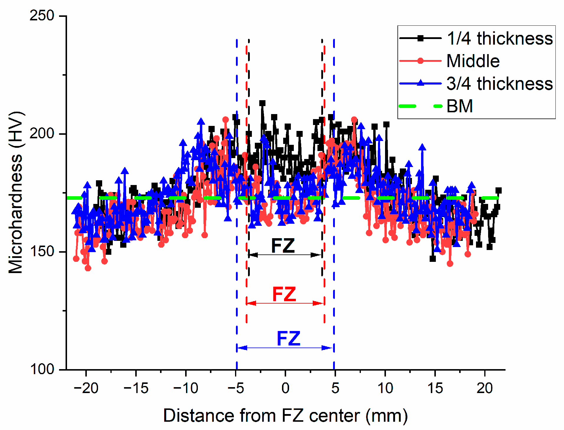
3.2.1. Microhardness Distribution

The Vickers microhardness tests were performed along the three lines shown in Figure 3a, at one-quarter, one-half, and three-quarter plate thickness. Vickers microhardness distributions across the weld are shown in Figure 4. The FZ widths were 7.4, 7.8, and 9.8 mm along the three microhardness measured lines, respectively. The across-FZ, -HAZ, and -BM microhardness results exhibited a “W” shape, a typical fusion-welded 304L SS hardness distribution with the lowest hardness in the HAZ [32,33,34]. Figure 4 shows that FZ microhardness measurements are higher than or similar to those of the BM value. The average FZ hardness values were 190.7, 172.2, and 175.5 HV at the three respective height locations. The BM average hardness value was 172.8 HV. In the plot, this value is indicated by a dashed green line for comparison. The FZ hardness at one-quarter thickness, which was in the first pass weld, is higher than those at the other two thickness locations. This result is likely due to the lower BM dilution of the filler metal between the two passes. For all height locations, the HAZ microhardness values near the FZ were higher than the BM hardness, but those far from the FZ had lower microhardness values.

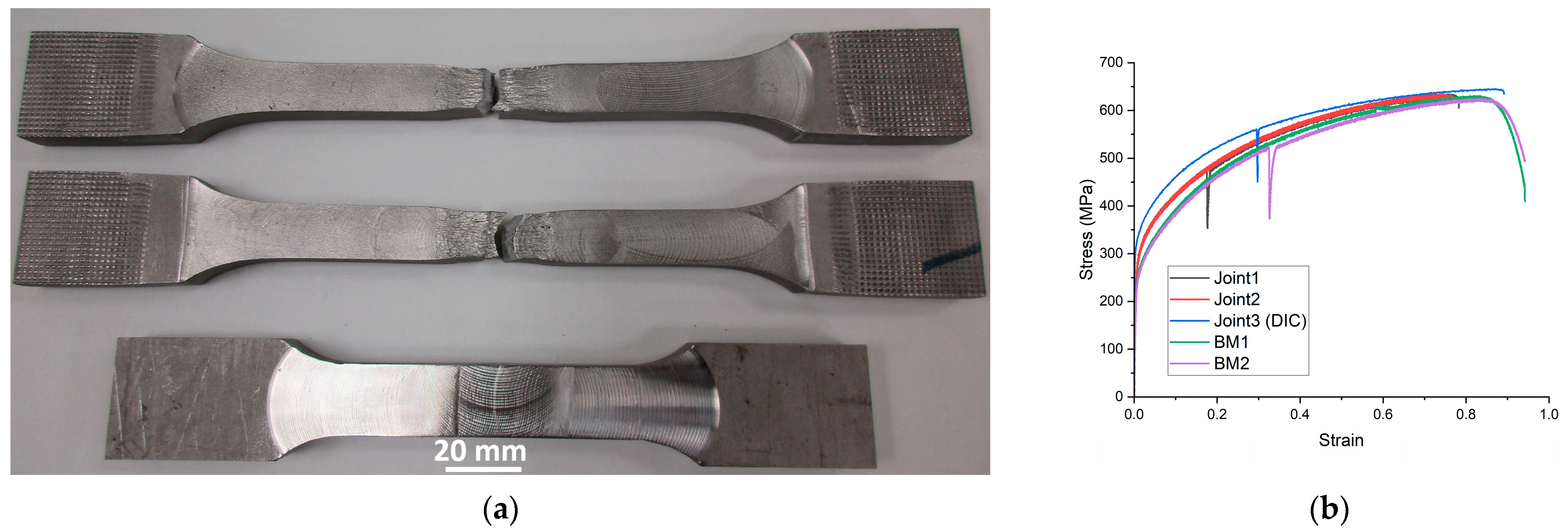
3.2.2. Tensile Properties
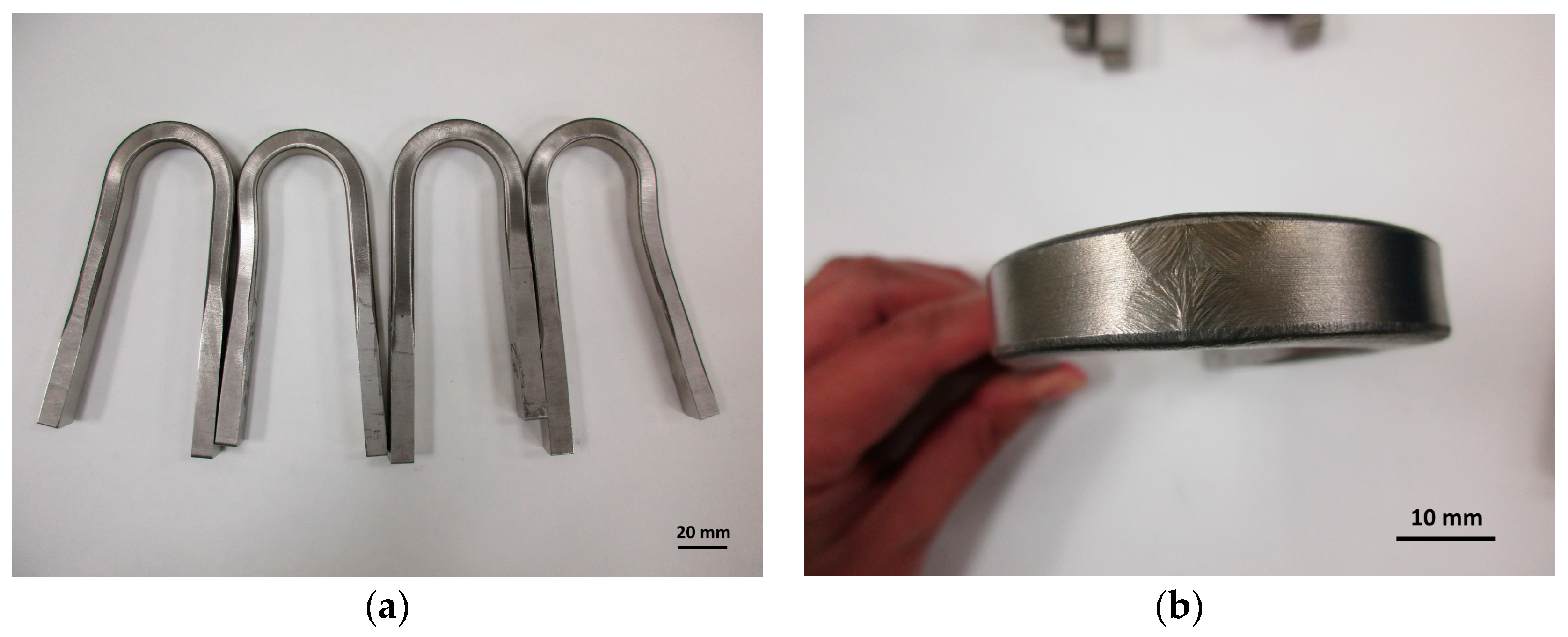
All tensile test specimens broke at the FZ. Selected tensile specimens and all tensile curves are shown in Figure 5, and tensile properties are listed in Table 4. Broken tensile specimens in Figure 5a showed significant plastic deformation at the gauge section before they failed at the FZ, indicating excellent uniform deformation before necking. Figure 5b shows load drops for a few tensile curves. These drops were caused by the slipping between the testing machine grips and the tensile specimen. Average tensile properties and standard deviations are also listed in Table 4. The SAW joint specimen yield strengths (YSs) were clearly higher than the those of the BM, and the ultimate tensile strengths (UTSs) were about the same. The YS, UTS, and elongation of the AISI 304L SS welded joints are comparable with those in other studies [31,32,33,34]. Moreover, the SAW joint UTS (~635 MPa) is higher than the ASME BPVC Section IX tensile strength minimum requirement of 482.6 MPa (70 ksi) [26]. Finally, all specimens exhibited very good uniform elongation and total elongation.

3.3. Bend Tests

Bend tests were performed using a wraparound tester, as described in the previous section; tested specimens are shown in Figure 6. All tested specimens attained about 180° bent shapes, as shown in Figure 6a, satisfying the bend test requirements from the ASME BPVC Section IX [26]. Furthermore, the joint FZ/HAZ boundaries and columnar dendritic structures in the FZ are clearly shown on the deformed surface in Figure 6b, indicating a huge amount of plastic deformation. Nevertheless, no cracks were observed in the FZ or HAZ on any of the tested specimens; thus, passed the ASME requirement [26].
Combining the welded joint tensile strength and the bend test results, as well as nondestructive inspections, the SAW process used in this study was qualified in accordance with ASME BPVC Section IX [26].
The FZ area, estimated from the welded joint cross section in Figure 3a, is about 143 mm2, and that of the welded joint following the current SNF canister production [25] was about 362 mm2. This study applied two SAW passes to join the AISI 304/304L SS plates, while the SNF canister was joined with seven to eight SAW passes [25]. Moreover, in this study, the welding speed was 8.47 mm/s, and that of the SNF canister was about 6.71 mm/s. Therefore, the SAW working efficiency of this study increased about 80%, compared with the industrial welding procedure, and the time and labor savings on supplemental work, such as grinding and inspection, are not included.

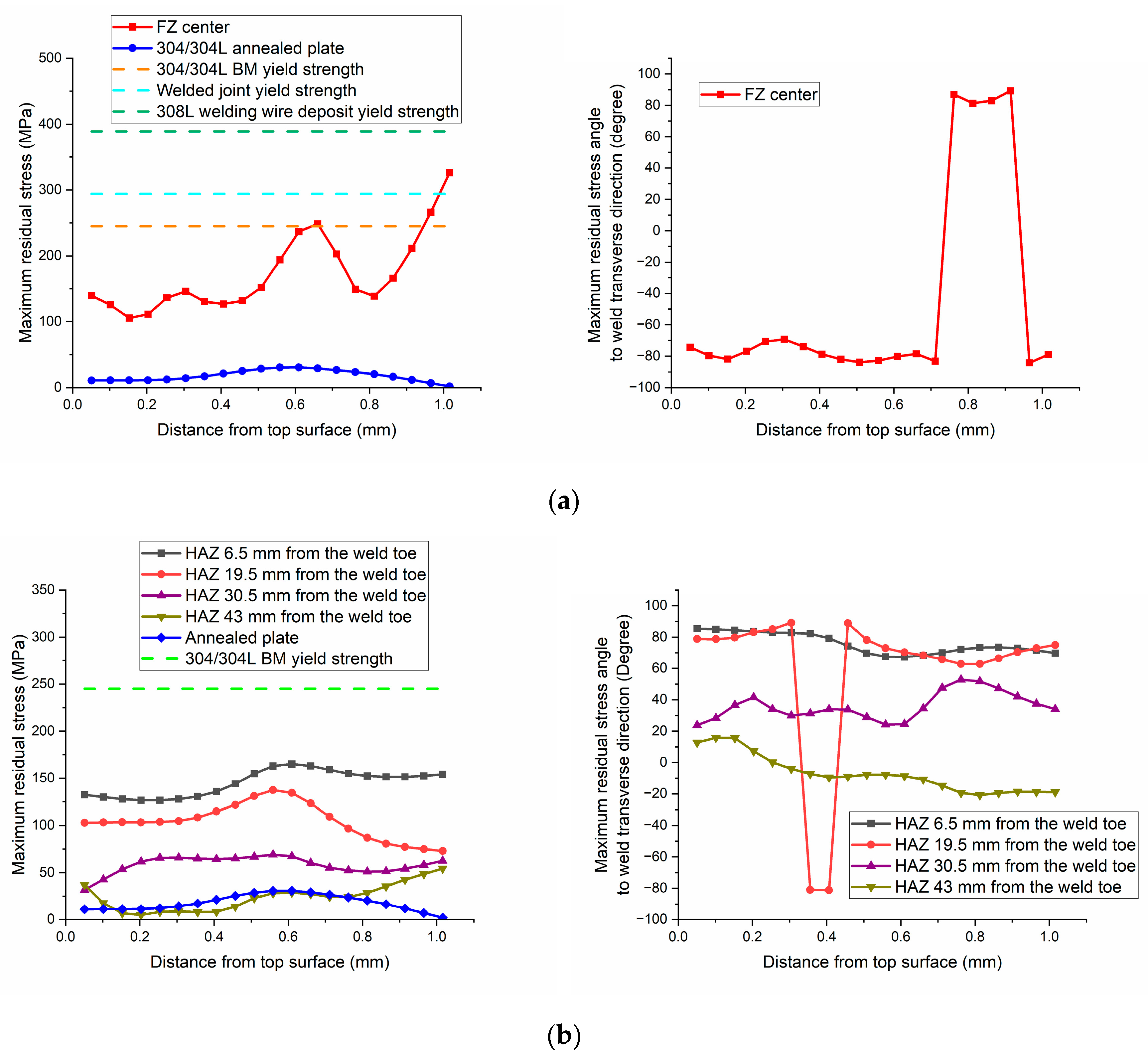
3.4. Residual Stress Measurements

As previously mentioned, the residual stresses were measured and calculated per ASTM E837 [30]. Maximum or principal residual stresses, and their orientations at different locations, measured by the hole drilling technique, are shown in Figure 7. In addition to the FZ and HAZ maximum residual stress distributions, the annealed AISI 304/304L SS plate residual stress, the as-received AISI 304/304L SS YS, the welded joint YS, and the filler material 308L SS tensile YS are also plotted in Figure 7. As expected, all measured residual stresses inside the FZ and nearby HAZ were tensile stresses. The highest tensile residual stresses were measured at the FZ center. These stresses were higher than the AISI 304/304L BM and the welded joint YSs, but lower than the 308L welding wire YS. The HAZ residual stresses were lower than the AISI 304/304L BM YS, and they gradually decreased as measuring locations moved away from the FZ/HAZ boundary. Because the welded plate was not a thin sheet, and the welding heat source was nonuniform through the thickness, residual stresses measured through the thickness direction were not uniform. After annealing, residual stresses in the BM-only specimen were very low, with a maximum value of ~30 MPa, effectively validating the hole drilling procedures.

4. Discussions

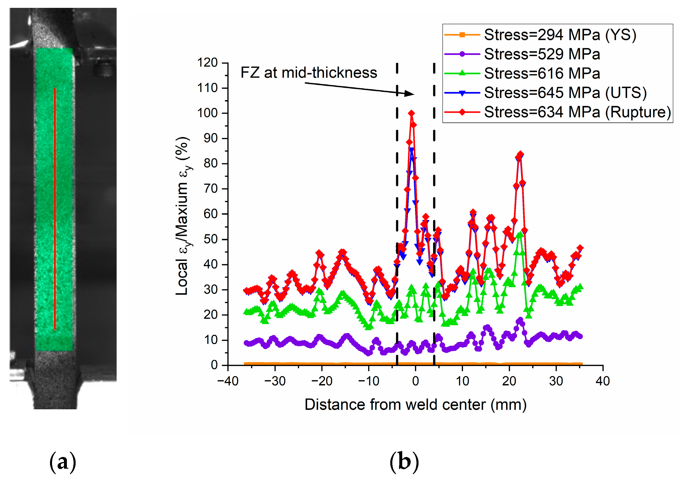
4.1. Local Deformation Behavior in Weld Transverse Tensile Test

After the tensile test, strains along the pulling direction can be calculated via DIC. In this study, the tensile strain at each point along the red line in Figure 8a was extracted at different stress levels. The tensile strain ratio was calculated, using each strain divided by the maximum strain along the line before specimen failure. Figure 8b shows the tensile strain ratio along the red line at several specific stress levels. In Figure 8b, 294, 645, and 634 MPa represent stress levels at the global YS, UTS, and rupture stress, respectively. As shown in Figure 8b, the maximum tensile strains at the 529 and 616 MPa stress levels, which were stresses between the YS and UTS, occurred in the HAZ at about 22 mm from the weld center. These locations correspond to the minimum HAZ hardness locations shown in Figure 4. In contrast, the maximum strains at the 645 and 634 MPa stress levels, which were the UTS and rupture stress, occurred at the weld centerline, and slightly lower strain values occurred in the HAZ minimum hardness locations. Therefore, strain localization first occurred in the minimum hardness HAZ locations after yield, and then shifted to the FZ after UTS and remained in the FZ as the tensile process approached rupture stress levels.
The chemistry of the FZ comprised a mix of AISI 304/304L SS BM and 308L welding wire. The 308L welding wire YS (389 MPa) is higher than that of the AISI 304/304L SS (245 MPa), and the mix of the two materials resulted in higher YS in the FZ than in the HAZ and BM. Therefore, tensile strain peaks appeared in the HAZ after yield. However, the welding wire UTS (549 MPa) was lower than that of the AISI 304/304L SS (628 MPa) and was likely lower than the that of the HAZ material. Therefore, the local strain peaks shifted in the FZ after UTS.
The DIC technique was used to reveal strain localization in the welded joint tensile test [35,36], but strain localization spot shifting has not been seen in the literature. The similar but mismatched YS and UTS at different metallurgical zones caused strain localization spot shifting during the loading process. Such strain localization and location shifting information are important for potential low-stress damage assessment, such as CISCC and fatigue, for which the degradation may occur at another location (HAZ), different from the tensile failure location (FZ).

4.2. Residual Stress Distribution

Tensile residual stress peak values and distributions are major factors affecting a structure’s SCC resistance. Other factors influencing SCC behavior include environment, material composition, microstructure, and temperature [13]. Welding joins materials via local heating, melting, solidification, and cooling, and these local metallurgical processes always result in significant residual stresses in the welded joint. Specifically, tensile residual stresses exist in the FZ, and in the HAZ region close to the FZ, and compressive residual stresses present in the far HAZ, and in the BM adjacent to the HAZ. Combining factors such as residual stress, thermal history, chemical composition, and microstructure, the HAZ region immediately outside the fusion line is the area that is most susceptible to SCC [13,20,21,22,23].
Multiple welding passes can result in more complicated residual stress distributions and, possibly, higher tensile residual stresses. Furthermore, the multiple thermal cycles that occur with many welding passes may lead to more undesired microstructures and degraded joint properties, such as large columnar grain size and ferrite ratio, as well as low ductility and fracture toughness [37]. In research by Nam et al. [38], artificial SCC was induced in STS 304 welds by reproducing operation environments of more than 350 °C and 180 bar in nuclear power plant primary systems. Four pipes that had been welded using 1-pass, 5-pass, 10-pass, and 15-pass processes were subjected to the SCC test, and a 3D finite element method was used for heat transfer analysis and residual stress analysis. Results showed that increasing the number of weld passes increased the tensile residual stress and decreased the time before SCC initiation. Therefore, when other parameters are similar, SNF canisters produced with fewer welding passes may exhibit lower tensile residual stress in the HAZ, better microstructure, and higher SCC resistance than those produced using more welding passes.
A comparison of residual stress values in Figure 7a,b reveals that FZ residual stress peak values are higher than those in the HAZ because the SAW filler material, 308L SS, has a higher YS (389 MPa [39]) than the AISI 304/304L SS BM (245 MPa). Furthermore, the HAZ tensile residual stresses measured here may not be the highest in this metallurgical zone, owing to the measuring locations.
In the HAZ, residual stress peak values were higher at locations that were closer to the fusion line. However, none of the measured maximum residual stresses reached the BM YSs, and the highest peak value, 165 MPa, was measured at a location 6.5 mm away from the weld toe. In the Sandia report [25], the highest HAZ tensile residual stresses measured by hole drilling, within 1 mm below the surface for a circumference weld and a longitudinal weld, were about 230 and 220 MPa, respectively. Obviously, measured HAZ peak residual stress of the two- pass welded joint in this study was lower than those of the seven- or eight-pass welded joints [25]. However, conditions were not the same in the two studies. In the current study, residual stress was measured on a 228.6 mm × 304.8 mm × 12.7 mm 304L SS welded coupon, and the HAZ measurement location closest to the FZ was 6.5 mm from the weld toe. In the Sandia study [25], residual stress was measured on a piece of mockup canister (1714.5 mm diameter, 1828.8 mm length, and 19.1 mm thickness), and the HAZ residual stress measurement was described as immediately adjacent to the FZ. Pictures show strain gauges close to the fusion line. Therefore, the two studies may show the trends, but direct comparisons are not valid without further information and/or additional experiments.
The principal residual stresses located at the FZ center and the two HAZ locations (i.e., 6.5 and 19.5 mm from the weld toe) were ~80°–90° to the weld transverse direction, as shown in Figure 7, indicating that the high principal tensile residual stresses in the FZ and HAZ were along the welding direction. Therefore, the potential CISCC orientation would likely be perpendicular to the welding direction. The sign change in the residual stress angles in Figure 7 indicates artificial effects that occurred during the calculation. All normal forces appear in pairs opposite to each other: +90° and −90° angles are a pair of normal forces.
In Figure 7a, the FZ center residual stress values and measurement scatter increase as the measuring position deepens. Generally, weld surface and near-surface residual stresses are lower than those at relatively deeper locations within the same weld pass, mainly because constraints at the surface and near-surface locations are fewer than those at deeper locations. Furthermore, cooling rates at the surface and near-surface locations are faster than those at deeper locations. In hole drilling residual stress measurement, strain gauges are attached to the coupon surface; hence, strain changes caused by material removal at locations close to the surface are more directly/accurately reflected by strain gauges, whereas corrections are needed to reflect strain changes at deeper locations. Therefore, in shallow hole drilling residual stress measurements, scatter is more pronounced at deeper locations than at near-surface locations.

5. Summary and Conclusions

Aiming to reduce costs in materials, labor, and time for SNF canister production, as well as to reduce the SCC potential, a double-sided, two-pass SAW procedure was developed, qualified by ASME BPVC section IX, and studied. The new procedure yielded cost savings (SAW working efficiency increased about 80%), improved mechanical properties, and presented moderate residual stresses.
The two-pass welding process produced fully penetrated welds, with typical refined columnar dendritic microstructures. Microhardness measurements in the FZ were slightly higher or similar to those in the BM. Outside of the FZ, the HAZ microhardness varied from high to low, and then increased back to BM hardness. The welded joint’s lowest hardness presented in the HAZ, about 20 mm away from the FZ center. The welded joint exhibited higher YS, similar UTS, and comparable elongation to the 304L SS BM at room temperature. Because of the addition of relatively high-YS and low-UTS 308L welding wire material in the FZ, local strain peak in the tensile test was initiated in the HAZ after yield, then shifted to the FZ after the stress reached UTS, and stayed in the FZ until the specimen broke. Such strain localization spot shifting may affect the damage initiation location under low and high stresses. Moderate principal tensile residual stresses were measured in the FZ and the HAZ. The FZ’s maximum principal residual stress was higher than the AISI 304/304L BM and welded joint YSs, but lower than the 308L welding wire YS. The HAZ’s maximum principal residual stress was lower than the AISI 304/304L BM YS. The principal residual stresses in the FZ and the high principal residual stresses in the HAZ were along the welding direction. Therefore, the potential CISCC orientation is perpendicular to the welding direction.

6. Acknowledgments

This is a technical paper that does not take into account contractual limitations or obligations under the Standard Contract for Disposal of Spent Nuclear Fuel and/or High-Level Radioactive Waste (Standard Contract) (10 CFR Part 961). For example, under the provisions of the Standard Contract, spent nuclear fuel in multi-assembly canisters is not an acceptable waste form, absent a mutually agreed to contract amendment. To the extent discussions or recommendations in this paper conflict with the provisions of the Standard Contract, the Standard Contract governs the obligations of the parties, and this paper in no manner supersedes, overrides, or amends the Standard Contract. This paper reflects technical work which could support future decision making by the U.S. Department of Energy (DOE or Department). No inferences should be drawn from this paper regarding future actions by the DOE, which are limited by both the terms of the Standard Contract and Congressional appropriations for the Department to fulfill its obligations under the Nuclear Waste Policy Act, including licensing and construction of a spent nuclear fuel repository.
This manuscript has been authored by UT-Battelle LLC, under contract DE-AC05-00OR22725 with the US Department of Energy (DOE). The US government retains, and the publisher, by accepting the article for publication, acknowledges that the US government retains, a nonexclusive, paid-up, irrevocable, worldwide license to publish or reproduce the published form of this manuscript, or allow others to do so, for US government purposes. The DOE will provide public access to these results of federally sponsored research in accordance with the DOE Public Access Plan (http://energy.gov/downloads/doe-public-access-plan (accessed on 28 January 2024).
The authors gratefully acknowledge the welding operation and coupon/specimen preparation by Doug Kyle, the residual stress measurement training and guidance of Yanli Wang and Christopher Stevens, the metallographic specimen preparation and characterization by Tom Geer and Victoria Cox, the tensile tests by Donald Erdman and Rick Lowden, and the radiographical inspection by Jessica Osborne, along with the specimen and coupon machining conducted by technicians at the Oak Ridge National Laboratory machine shop.

Author Contributions

Conceptualization, S.C., R.H., W.T. and R.G.M.; methodology, W.T., R.G.M. and S.C.; validation, W.T. and S.C.; formal analysis, W.T., C.M.S. and S.C.; investigation, C.M.S., W.T., R.G.M. and S.C.; data curation, C.M.S. and W.T.; writing—original draft preparation, W.T. and S.C.; writing—review and editing, W.T., S.C., R.G.M. and R.H.; visualization, W.T. and S.C.; supervision, W.T., S.C. and R.H.; project administration, S.C., R.H. and W.T.; funding acquisition, S.C. and R.H. All authors have read and agreed to the published version of the manuscript.

Funding

This research was funded by the Spent Fuel and Waste Disposition Program for the US Department of Energy Office of Nuclear Energy, within work package SF-18OR02040801.

Data Availability Statement

The raw/processed data required to reproduce these findings cannot be shared at this time, owing to technical or time limitations. However, the raw/processed data required to reproduce these findings will be made available upon request and with the approval of the DOE office.

Conflicts of Interest

Author Robert Howard was employed by the company Spectra Tech Inc. The remaining authors declare that the re-search was conducted in the absence of any commercial or financial relationships that could be construed as a potential conflict of interest.

References

  1. Kadak, A.C.; Yost, K. Key Issues Associated with Interim Storage of Used Nuclear Fuel; Massachusetts Institute of Technology: Cambridge, MA, USA, 2010. [Google Scholar]
  2. Blue Ribbon Committee. Blue Ribbon Commission on America’s Nuclear Future; Report to the Secretary of Energy; Blue Ribbon Committee: Washington, DC, USA, 2012. [Google Scholar]
  3. United States Nuclear Waste Technical Review Board. Evaluation of the Technical Basis for Extended Dry Storage and Transportation of Used Nuclear Fuel; United States Nuclear Waste Technical Review Board: Arlington, VA, USA, 2010. [Google Scholar]
  4. Chopra, O.K.; Diercks, D.R.; Fabian, R.R.; Han, Z.H.; Liu, Y.Y. Managing Aging Effects on Dry Cask Storage Systems for Extended Long-Term Storage and Transportation of Used Fuel; ANL-13/15 rev. 2; Argonne National Laboratory: Lemont, IL, USA, 2014. [Google Scholar]
  5. Nuclear Energy Institute. Format, Content and Implementation Guidance for Dry Cask Storage Operations-Based Aging Management; NEI 14-03 rev. 2; Nuclear Energy Institute: Washington, DC, USA, 2016. [Google Scholar]
  6. Electric Power Research Institute. Aging Management Guidance to Address Potential Chloride-Induced Stress Corrosion Cracking of Welded Stainless Steel Canisters; 300200819; Electric Power Research Institute: Palo Alto, CA, USA, 2017. [Google Scholar]
  7. US Nuclear Regulatory Commission. Managing Aging Processes in Storage (MAPS) Report; Draft Report for Comment. NUREG-2214; US Nuclear Regulatory Commission: Rockville, MD, USA, 2017. [Google Scholar]
  8. Jones, R.H., Jr. Dry Storage Cask Inventory Assessment; FCRD-NFST-2014-000602; Savannah River National Laboratory: Jackson, SC, USA, 2017. [Google Scholar]
  9. Werner, J.D.U.S. Spent Nuclear Fuel Storage; Congressional Research Service: Washington, DC, USA, 2012. [Google Scholar]
  10. US Nuclear Regulatory Commission. Identification and Prioritization of the Technical Information Needs Affecting Potential Regulation of Extended Storage and Transportation of Spent Nuclear Fuel; US Nuclear Regulatory Commission: Rockville, MD, USA, 2014. [Google Scholar]
  11. Hanson, B.; Alsaed, H.; Stockman, C.; Enos, D.; Meyer, R.; Sorenson, K. Gap Analysis to Support Extended Storage of Used Nuclear Fuel; FCRD-USED-2011-000136 rev. 0, PNNL-20509; Pacific Northwest National Laboratory: Richland, WA, USA, 2012. [Google Scholar]
  12. Dong, P.; Scatigno, G.G.; Wenman, M.R. Effect of Salt Composition and Microstructure on Stress Corrosion Cracking of 316L Austenitic Stainless Steel for Dry Storage Canisters. J. Nucl. Mater. 2021, 545, 152572. [Google Scholar] [CrossRef]
  13. Davis, J.R. Corrosion of Weldments; ASM International: Materials Park, OH, USA, 2006. [Google Scholar]
  14. Connor, L.P. Residual Stress and Distortion. Welding Handbook: Welding Technology; American Welding Society: Doral, FL, USA, 1989; pp. 217–264. [Google Scholar]
  15. Chandra, U. Control of residual stresses. In ASM Handbook: Materials Selection and Design; ASM International: Materials Park, OH, USA, 1997; pp. 811–819. [Google Scholar]
  16. Kim, S.; Ahn, K.; Kim, G.; Song, S.-W. Synchrotron X-ray fluorescence imaging study on chloride-induced stress corrosion cracking behavior of austenitic stainless steel welds via selective corrosion of δ-ferrite. Corros. Sci. 2023, 218, 111176. [Google Scholar] [CrossRef]
  17. Lee, D.; Kim, Y.; Cho, S. Evaluation of Residual Stress on Welds of Spent Fuel Dry Storage Canisters by Peening Technology. In Proceedings of the Transactions of the Korean Nuclear Society, Virtual spring Meeting, 13–14 May 2021. [Google Scholar]
  18. John, M.; Ralls, A.M.; Misra, M.; Menezes, P.L. Effect of ultrasonic impact peening on stress corrosion cracking resistance of austenitic stainless-steel welds for nuclear canister applications. J. Nucl. Mater. 2023, 584, 154590. [Google Scholar] [CrossRef]
  19. John, M.; Ralls, A.M.; Misra, M.; Menezes, P.L. Understanding the Mechanism of Stress Corrosion Cracking Resistance in Stainless Steel Welds Subjected to Laser Shock Peening without Coating for Nuclear Canister Applications. J. Mater. Eng. Perform. 2024, 21. [Google Scholar] [CrossRef]
  20. International Atomic Energy Agency. Stress Corrosion Cracking in Light Water Reactors: Good Practices and Lessons Learned; IAEA Nuclear Energy Series, No. NP-T-3.13; International Atomic Energy Agency: Vienna, Austria, 2011. [Google Scholar]
  21. US Nuclear Regulatory Commission. Potential Chloride-Induced Stress Corrosion Cracking of Austenitic Stainless Steel and Maintenance of Dry Cask Storage System Canisters; US Nuclear Regulatory Commission: Rockville, MD, USA, 2012. [Google Scholar]
  22. Okamura, Y.; Sakashita, A.; Fukuda, T.; Yamashita, H.; Futami, T. Latest SCC issues of core shroud and recirculation piping in Japanese BWRs. In Proceedings of the 17th International Conference on Structural Mechanics in Reactor Technology, Prague, Czech Republic, 17–22 August 2003. [Google Scholar]
  23. Saukkonen, T.; Aalto, M.; Virkkunen, I.; Ehrnstén, U.; Hänninen, H. Plastic strain and residual stress distributions in an AISI 304 stainless steel BWR pipe weld. In Proceedings of the 15th International Conference on Environmental Degradation of Materials in Nuclear Power Systems—Water Reactors; Springer: Cham, Switzerland, 2011; pp. 2351–2367. [Google Scholar]
  24. Chatzidakis, S.; Giuliano, D.; Slade, J.; Tang, W.; Miller, R.; Reeves, S.; Scaglione, J.; Howard, R. A Versatile Remediation Module for Remote Repair of Spent Nuclear Fuel and High-Level Waste Storage Containers. Nucl. Technol. 2021, 207, 750–760. [Google Scholar] [CrossRef]
  25. Enos, D.G.; Bryan, C.R. Final Report: Characterization of Canister Mockup Weld Residual Stress; FCRD-UFD-2016-000064; Sandia National Laboratories: Albuquerque, NM, USA, 2016. [Google Scholar]
  26. ASME Boiler and Pressure Vessel Code IX, Qualification Standard for Welding, Brazing, and Fusing Procedures; Welders; Brazers; and Welding, Brazing, and Fusing Operators; American Society of Mechanical Engineers: New York, NY, USA, 2013.
  27. SA-240/SA-240M; Specification for Chromium and Chromiumnickel Stainless Steel Plate, Sheet, and Strip for Pressure Vessels and for General Applications. ASTM: West Conshohocken, PA, USA, 2007.
  28. North American Stainless, Inspection Certificate #377084 01, 2018.
  29. ASTM E8/E8M; Standard Test Methods for Tension Testing of Metallic Materials. ASTM International: West Conshohocken, PA, USA, 2021.
  30. ASTM E837-13a; Standard Test Method for Determining Residual Stress by the Hole-Drilling Strain-Gage Method. ASTM International: West Conshohocken, PA, USA, 2013.
  31. Sridhar, P.V.S.S.; Biswas, P.; Mahanta, P. Effect of process parameters on bead geometry, tensile and microstructural properties of double-sided butt submerged arc welding of SS 304 austenitic stainless steel. J. Braz. Soc. Mech. Sci. Eng. 2020, 42, 551. [Google Scholar] [CrossRef]
  32. Nam, T.-H.; An, E.; Kim, B.J.; Shin, S.; Ko, W.-S.; Park, N.; Kang, N.; Jeon, J.B. Effect of Post Weld Heat Treatment on the Microstructure and Mechanical Properties of a Submerged-Arc-Welded 304 Stainless Steel. Metals 2018, 8, 26. [Google Scholar] [CrossRef]
  33. Saha, S.; Mukherjee, M.; Pal, T.K. Microstructure, Texture, and Mechanical Property Analysis of Gas Metal Arc Welded AISI 304 Austenitic Stainless Steel. J. Mater. Eng. Perform. 2015, 24, 1125–1139. [Google Scholar] [CrossRef]
  34. Kumar, S.; Shahi, A.S. On the Influence of Welding Stainless Steel on Microstructural Development and Mechanical Performance. Mater. Manuf. Process. 2014, 29, 894–902. [Google Scholar] [CrossRef]
  35. Boyce, B.L.; Reu, P.L.; Robino, C.V. The Constitutive Behavior of Laser Welds in 304L Stainless Steel Determined by Digital Image Correlation. Metall. Mater. Trans. A 2006, 37A, 2481–2492. [Google Scholar] [CrossRef]
  36. Switzner, N.; Yu, Z.; Eff, M.; Lienert, T.; Fonseca, A. Microstructure and mechanical property variations within inertia friction-welded joints of stainless steel to steel. Int. J. Adv. Manuf. Technol. 2018, 95, 4327–4340. [Google Scholar] [CrossRef]
  37. Gowrisankar, I.; Bhaduri, A.K.; Seetharaman, V.; Verma, D.D.N.; Achar, D.D.G. Effect of the number of passes on the structure and properties of submerged arc welds of AISI type 316l stainless steel. Weld. Res. Suppl. 1987, 66, 147-s–154-s. [Google Scholar]
  38. Nam, J.Y.; Seo, D.H.; Lee, S.Y.; Hwang, W.K.; Lee, B.Y. The effect of residual stress on the SCC using ANSYS. Procedia Eng. 2011, 10, 2609–2614. [Google Scholar] [CrossRef]
  39. Lincoln Electric. Lincolnweld® 308/308L. Available online: https://www.lincolnelectric.com/en/products/lincolnweld308308l_saw (accessed on 18 January 2024).
Figure 1. The cross section of two edge-machined plates, forming 60° double-V grooves.
Metals 14 00262 g001
Figure 2. Dimensions of the (a) tensile test specimen and (b) bend test specimen.
Metals 14 00262 g002
Figure 3. AISI 304/304L SS submerged arc welded joint cross section and microstructure: (a) weld cross section, (b) BM, (c) the first pass weld center, and (d) the second pass weld center.
Metals 14 00262 g003
Figure 4. Microhardness distributions of the AISI 304/304L welded joint.
Metals 14 00262 g004
Figure 5. Tensile curves of 304L SS SAW joints and BM. (a) Tensile specimens before and after the test and (b) tensile curves.
Metals 14 00262 g005
Figure 6. Transverse side bend-tested AISI 304/304L SS welded joint specimens: (a) bend-tested specimens and (b) deformed welded joint.
Metals 14 00262 g006
Figure 7. Maximum residual stresses and orientations in the FZ and HAZ of the AISI 304/304L SS welded joint. (a) FZ center maximum residual stresses and directions and (b) HAZ maximum residual stresses and directions.
Metals 14 00262 g007
Figure 8. Local strain distribution along the tensile direction. (a) Local strain calculation line and (b) local strain ratio distributions.
Metals 14 00262 g008
Table 1. Chemical composition of the AISI 304/304L SS [28] (wt %).
CCrMnNiPSNSiFe
0.027118.05251.79508.02700.03200.00100.05920.2395Balance
Table 2. Chemical composition of the 308L welding wire (wt %).
CCrMnNiPSNSiMoNbCuFe
0.0120.01.910.10.02<0.010.050.310.06<0.010.19Balance
The SAW power source was a Miller Intelliweld 650 (Miller Intelliweld, Appleton, WI, USA), and the SAW controller was a Miller Automatic 1DA (Appleton, WI, USA).
Table 3. Submerged arc welding parameters.
Welding Current (A)Welding Voltage (V)Welding Speed (mm/s)Welding Wire Feed Speed (mm/s)
450308.4759.3
Table 4. Tensile properties of 304L SS joints and BMs.
Specimen IDYield Strength (MPa)Ultimate Tensile Strength (MPa)Uniform Elongation (%)Total Elongation (%)
MeasuredAverage ± Standard DeviationMeasuredAverage ± Standard DeviationMeasuredAverage ± Standard DeviationMeasuredAverage ± Standard Deviation
Joint1316304 ± 12635638 ± 675.8378.22 ± 7.9778.2581.52 ± 6.64
Joint229863471.7277.16
Joint3 (DIC)29464587.1189.16
BM1243245 ± 2631628 ± 481.9683.98 ± 2.8694.2894.21 ± 0.11
BM22466258694.13
Disclaimer/Publisher’s Note: The statements, opinions and data contained in all publications are solely those of the individual author(s) and contributor(s) and not of MDPI and/or the editor(s). MDPI and/or the editor(s) disclaim responsibility for any injury to people or property resulting from any ideas, methods, instructions or products referred to in the content.

