Article

Evolution of the Heterogeneous Microstructure of a 12Cr1MoV Welded Joint after Post-Weld Heat Treatment and Its Effect on Mechanical Properties

1
College of New Energy, China University of Petroleum (East China), Qingdao 266580, China
2
College of Mechanical and Electronic Engineering, Shandong University of Science and Technology, Qingdao 266590, China
*
Author to whom correspondence should be addressed.
Metals 2023, 13(12), 1998; https://doi.org/10.3390/met13121998
Submission received: 7 November 2023 / Revised: 5 December 2023 / Accepted: 10 December 2023 / Published: 12 December 2023
(This article belongs to the Special Issue Advances in High-Strength Low-Alloy Steels (2nd Edition))

Abstract

:
The non-uniformity of microstructures and mechanical properties across a whole welded joint is a crucial factor leading to its weakening performance and premature failure. Post-weld heat treatment is a primary method for increasing the mechanical properties. However, the evolution mechanism of mechanical properties related to heterogeneous microstructure after heat treatment remains unclear, making it challenging to design the heat treatment process and evaluate its effect comprehensively. In this study, microstructure characterization and a series of mechanical tests of 12Cr1MoV welded joint after the stress relief annealing (SRA) and tempering heat treatment (THT) were conducted. The effect of heat treatment on mechanical properties is analyzed based on the comparison between stress relief annealing and tempering heat treatment in terms of tensile properties, impact toughness, and impact fracture morphology. The results indicate that, after the tempering heat treatment, the evolution of mechanical properties in each subzone of the joint is consistent, i.e., the hardness and tensile strength decreased while the toughness increased. Notably, the most substantial enhancement in toughness is observed in the weld zone, primarily due to a significant reduction in the presence of pre-eutectoid ferrite. Furthermore, it is proved that hardness is an indicator to reflect changes in tensile strength related to the microstructure evolution, which indicates it can be employed to evaluate the effectiveness of post-weld heat treatment in practical engineering.

1. Introduction

Welded joints, as a critical connection structure, often experience premature failure. Moreover, the failure modes of welded joints change with the change in loading conditions. Welded joints typically consist of various subzones including base material (BM), heat-affected zone (HAZ), and weld metal (WM) [1,2]. The heterogenous microstructure and mechanical properties of welded joints is a key contributing factor to their performance degradation and premature failure [3,4]. Post-weld heat treatment is a primary means of improving the microstructure and overall performance of welded joints [5,6,7,8]. Considering the non-uniform characteristics of welded joints [9,10,11,12,13], it is essential to design a scientific heat treatment process according to specific working conditions. Therefore, a comprehensive understanding of the evolution of microstructure and mechanical properties in different subzones of the welded joint and the influence of heat treatment processes on this evolution is crucial.
The typical post-weld heat treatment processes include dehydrogenation heat treatment, stress relieving heat treatment, tempering heat treatment and so on [14,15,16,17,18]. Different process methods and parameters have a great influence on the performance. Schönmaie et al. studied the impact of post-weld heat treatment on the microstructure and mechanical properties of 2.25Cr–1Mo–0.25V weld metal and found that a longer PWHT-time could cause a reduction of strength and an increase of the weld metals ductility [19]. In order to enhance the toughness and other mechanical properties of API X60 steel pipe welded joints, Khalaj et al. proposed a new two-step post-weld heat treatment consisting of “quenching + tempering”, and prepared a variety of samples under different post-weld heat treatments to compare the joint properties with the traditional single-step normalizing post-weld heat treatment. The results show that the impact performance of the welded joint after the “quenching + tempering” two-step heat treatment is significantly improved, and by comparing the performance under multiple tempering heat treatment parameters, it is found that the best tempering temperature is 600 °C and the best tempering time is 30 min [20]. Dey studied the effects of post-weld heat treatment time and multiple post-weld heat treatments on the mechanical properties of 9Cr1Mo steel welded joints. The single heat treatment temperature was 760 °C, and the holding time was 1 h, 3 h, 4 h, 8 h and 12 h. The heat treatment temperature of multiple welding was also 760 °C. The holding time is the combination of “1 h + 3 h” and “4 h + 4 h”, and the joint properties were compared with the single heat treatment of holding for 4 h and 8 h, respectively. The results show that the impact toughness of 9Cr1Mo steel welded joints increased significantly after post-weld heat treatment, but tensile strength decreased slightly with the increase of heat treatment time. In addition, multiple post-weld heat treatment processes have no adverse effect on both the tensile and impact properties of welded joints [21]. It is worth noting that an unreasonable heat treatment process may deteriorate the performance [22,23,24]. Kromm et al. mentioned that welding of 13CrMoV9-10 vanadium steel requires care due to an increased susceptibility to stress relief cracking during post-weld heat treatment [25]. Chen discussed the selection of the post-weld heat treatment process for welded joints of SUMITEN610F low-carbon high-strength steel. One group of welded joints was treated with hydrogen removal at 200 °C × 2 h, and the other group was treated with stress removal at 600 °C × 2 h. The tensile, bending, impact, hardness and other mechanical properties of welded joints after different heat treatments were tested and evaluated. It was found that the mechanical properties of the welded joints obtained by dehydrogenation treatment at 200°C × 2 h met the requirements, while the stress relief treatment at 600°C × 2 h would reduce the properties of the welded joints [26]. Zhang et.al. analyzed reheat cracking in 12Cr1MoV steel welded joints after post-weld heat treatment and identified that heat treatment temperature is a critical factor for the reheat cracking [27]. In addition, some research focused on the evolution of both microstructure and mechanical properties after the post-weld heat treatment. Zhang et al. investigated the effect of post-weld heat treatment temperature on the carbon-manganese alloy steel welded joints and found that the heat treatment softened the ferrite during temperature holding, while the hardness of the acicular ferrite depended significantly on the temperatures [28]. Jiang Feng et al. discovered that post-weld heat treatment improved the cast structure significantly in the weld zone of Al-Mg-Sc alloy welded joints, leading to a substantial increase in both strength and toughness [29]. Wang et al. found that post-weld heat treatment promotes the decomposition of pearlite in 12Cr1MoV seamless steel pipe welded joints, as well as the growth of ferrite grains and carbides, thus reducing yield strength, tensile strength, and hardness but enhancing the toughness and elongation [30].
In summary, there is no uniform statement on the effect of the post-weld heat treatment process on the weld microstructure and mechanical properties, but it can be determined that the post-weld heat treatment process affects the joint properties by changing the microstructure. However, the existing research mainly focuses on the overall effect of post-weld heat treatment, and a systematic and detailed investigation of the heterogeneous microstructure evolution at different microzones of the joint is still required to better understand the heterogeneous mechanical performance after post-weld heat treatment.
Therefore, this study conducted a series of microstructure observations and mechanical properties measurements (including microhardness testing, standard tensile testing, micro-tensile testing, impact testing and fractography observation) for 12Cr1MoV pipeline welded joints after both stress relief annealing and tempering heat treatment. Based on the experimental findings, the intrinsic correlation among post-weld heat treatment process, microstructural characteristics and mechanical performance was discussed comprehensively.

2. Materials Preparation and Experimental Procedure

In this part, two sections of 12Cr1MoV steel pipe are selected as welding materials, and the welding process and test plan of pipeline butt welding are designed, as well as the stress relief annealing and tempering heat treatment process plan. The microstructure of the welded joint was observed, and the Vickers hardness distribution in each microzone was characterized. The standard rod-like tensile samples were used for the normal temperature tensile test, and the micro-tensile samples were used for the high-temperature tensile test. The impact toughness of the welded joint at different positions was measured and the impact fracture morphology was observed by electron probe.

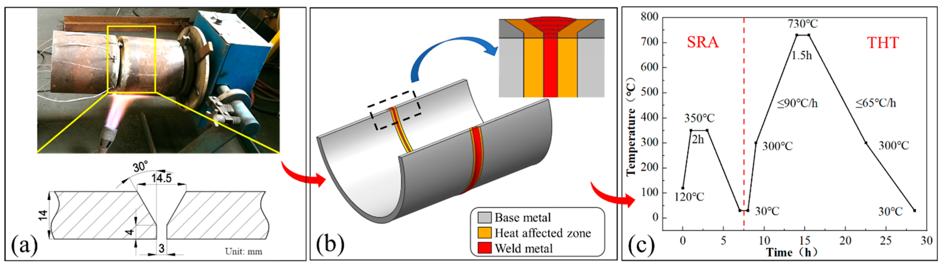
2.1. Materials and Welding Process

The 12Cr1MoV steel pipe joint evaluated in this study consists of two pipes with the size of Φ 168 mm × 14 mm. A single-sided V-shaped 60° groove was manufactured and preheated to approximately 200 °C before welding. In addition, manual shielded metal arc welding (SMAW) was employed with the filler material of R317 (E5515-B2-V). A total of six welding passes were applied. The welding procedure and the configuration of the welded joint are illustrated in Figure 1. The chemical compositions of base and filler metal are listed in Table 1, and the welding process parameters are provided in Table 2.

2.2. Post-Weld Heat Treatment Process

To better reveal the influence of heat treatment processes on the microstructural characteristics of the weld joint, a post-weld stress relief annealing and subsequent tempering heat treatment were performed. The stress relief annealing was conducted before the weld had cooled to 100 °C, while the tempering heat treatment parameters were determined based on actual factory manufacturing processes. The entire tempering process was carried out in a bogie-type resistance furnace. The heat treatment process parameters are listed in Table 3, and the post-weld heat treatment temperature profile is illustrated in Figure 1c.

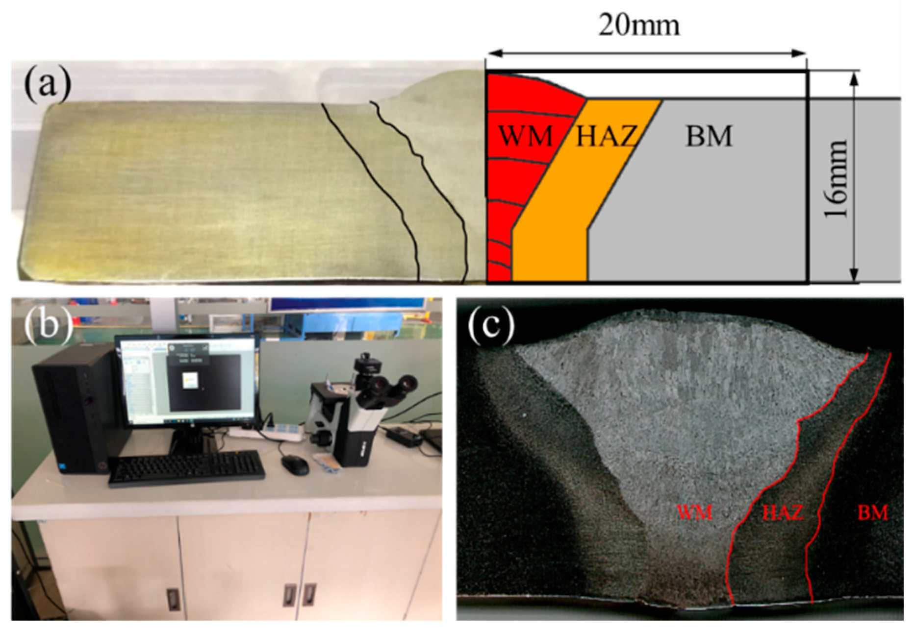
2.3. Microstructure Observation

The microstructure observation at different subzones of welded joints was conducted on an inverted metallurgical microscope (SDPTOP IE200M produced by Sunny Optical Technology Co., Ltd. in Dongguan, China), as shown in Figure 2. The samples were cut from the weld centerline at both stress relief annealing and tempering heat treatment conditions. Note that the sample with a size of 20 mm × 16 mm × 10 mm included the weld zone, heat-affected zone and base metal zone. After grinding and polishing, they were etched with a 4% nitric acid alcohol solution before final observation.

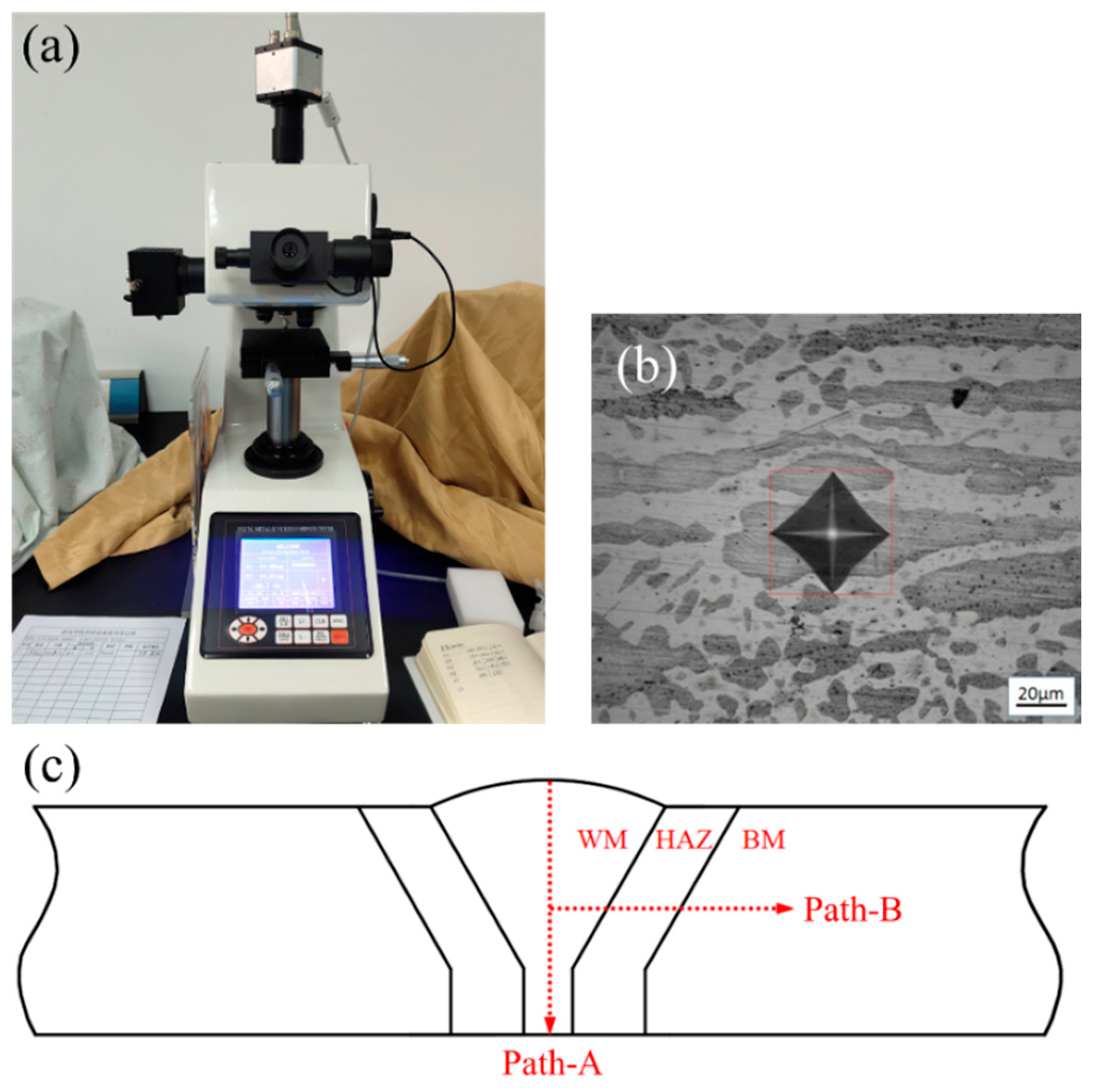
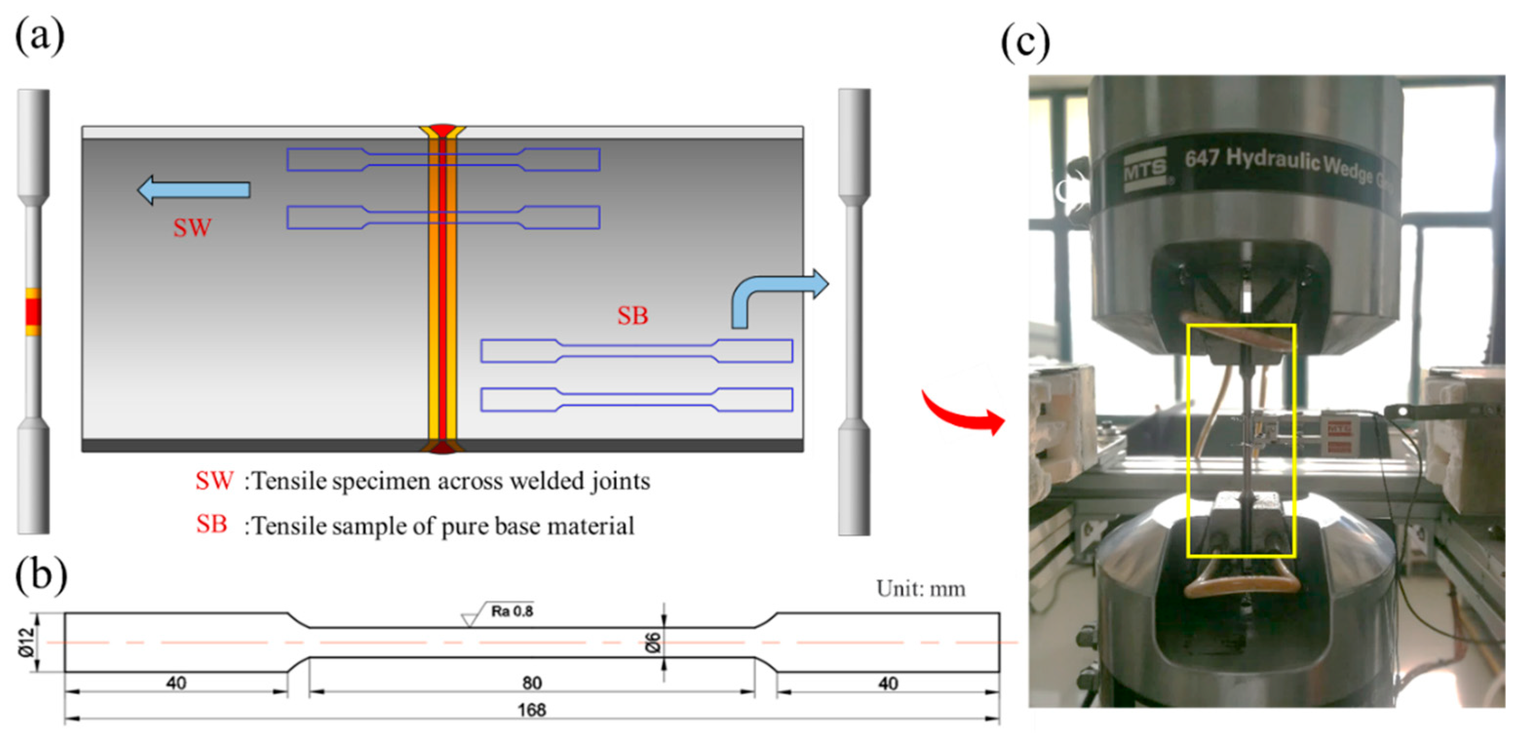
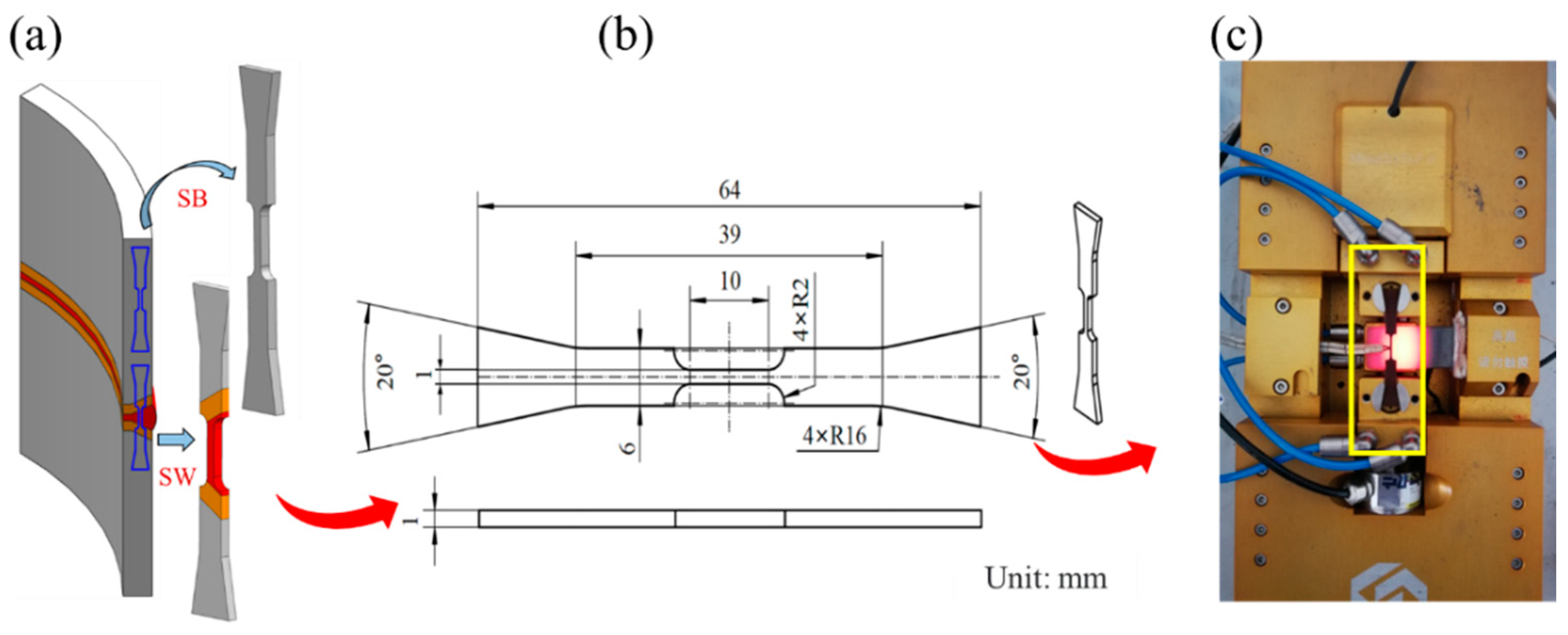
2.4. Measurement of Mechanical Properties

In order to comprehensively understand the mechanical performance of welded joints at the stress relief annealing and tempering heat treatment conditions, a series of mechanical tests were performed. Firstly, the microvickers hardness tests were carried out on the welded joints after stress relief annealing and tempering heat treatment using a TH-701 digital microvickers hardness tester (manufactured by ARTRAY Corporation of Japan). The test was conducted with an applied load of 1.96 N and a holding time of 15 s. The testing path and indentation morphology are illustrated in Figure 3. Secondly, the standard tensile tests of cross-welded joints were conducted in accordance with the standards GB/T 2651-2008 (Tensile Testing of Welded Joints) [31] and GB/T 228.1-2010 (Tensile Testing of Metallic Materials) [32]. The tensile tests were performed on an MTS series hydraulic servo universal testing machine (MTS Landmark 370.10 produced by MTS Systems (China) Co., Ltd. in Shanghai, China). During the tests, the displacement of the specimen was controlled at 0.5 mm/min up to the final rapture. The geometric configurations and sampling locations of the specimen are depicted in Figure 4.
Furthermore, since 12Cr1MoV steel pipe needs to be served in a high-temperature environment, in order to more comprehensively evaluate the effect of the stress relief annealing and tempering heat treatment, its tensile property at different temperatures from room temperature to high temperature was tested. Due to the limited availability of test materials, tensile tests of miniature specimens were conducted using a Mtest3000-F-K micro flat tensile testing machine (produced by Changchun Mechanical Science Research Institute Co., Ltd. in Changchun, China) to evaluate the tensile properties at different subzones under various temperatures. The displacement was controlled as 0.1 mm/min at different temperatures of 27 °C, 400 °C, 470 °C, 500 °C and 538 °C. The geometric configurations and sampling locations of miniature samples are shown in Figure 5. Finally, the impact testing of the welded joints at various micro-regions was also carried out at room temperature using a JBN-300 pendulum impact testing machine (produced by Jinan Union testing Technology Co., Ltd. in Jinan, China) following the standards GB/T 229-2007 (Charpy V-notch Impact Test on Metallic Materials) [33] and GB/T 2650-2008 (Impact Test on Welded Joints) [34]. Standard Charpy V-notch impact specimens were used with the notches oriented parallel to the weld bead. Note that impact properties at different subzones were evaluated based on the locations of the notch, and the fractography observation was also performed on the electron probe microanalyzer (JXA-8230 produced by JEOL (BEIJING) CO., Ltd. in Beijing, China). The geometric configurations and sampling locations of V-notch specimens are depicted in Figure 6. Note that in the tensile test and impact toughness test, three samples with the same sampling position were tested in each group of experiments, and the average value of test results was selected.

3. Results and Discussion

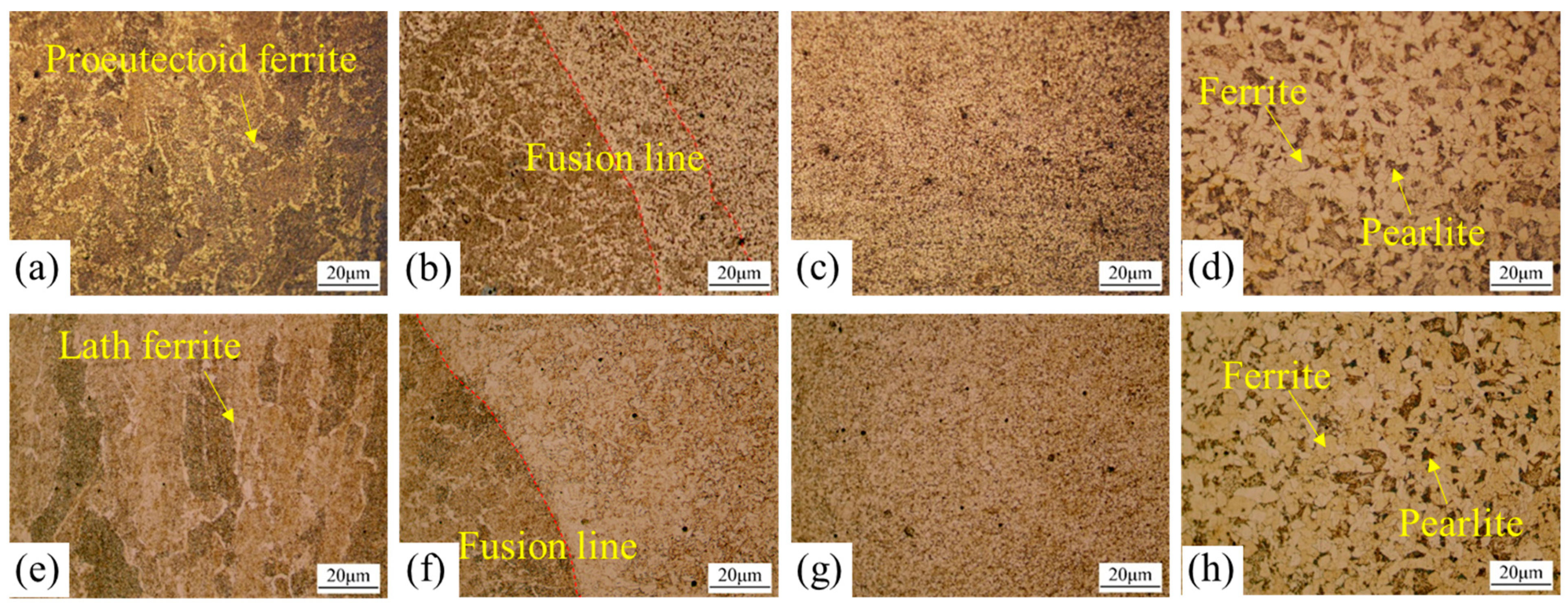
3.1. Evolution of Heterogeneous Microstructure

Figure 7 presents the microstructure at different zones of 12Cr1MoV welded joint at both stress relief annealing and tempering heat treatment conditions. A noticeable reduction in the content of primary coarsened ferrite is observed in the weld seam structure after tempering heat treatment (as shown in Figure 7a,e). Note that the blocky primary coarsened ferrite at the grain boundaries is always regarded as a main factor contributing to rapid crack propagation and decreased toughness. Consequently, it can be speculated that the overall performance of the weld seam may be significantly enhanced. In the coarse-grained heat-affected zone on the right side of the fusion line (Figure 7b,f), some of the bainite undergoes decomposition, and the characteristic plate-like ferrite structure becomes less distinct, leading to a more uniform microstructure distribution. In addition, after tempering heat treatment, the grain size in the fine-grained zone increases with the decomposition of some pearlite, and the ferrite grows larger (Figure 7c,g). In the base metal zone, there is no significant change in grain size, but the pearlite content notably decreases, as shown in (Figure 7d,h).

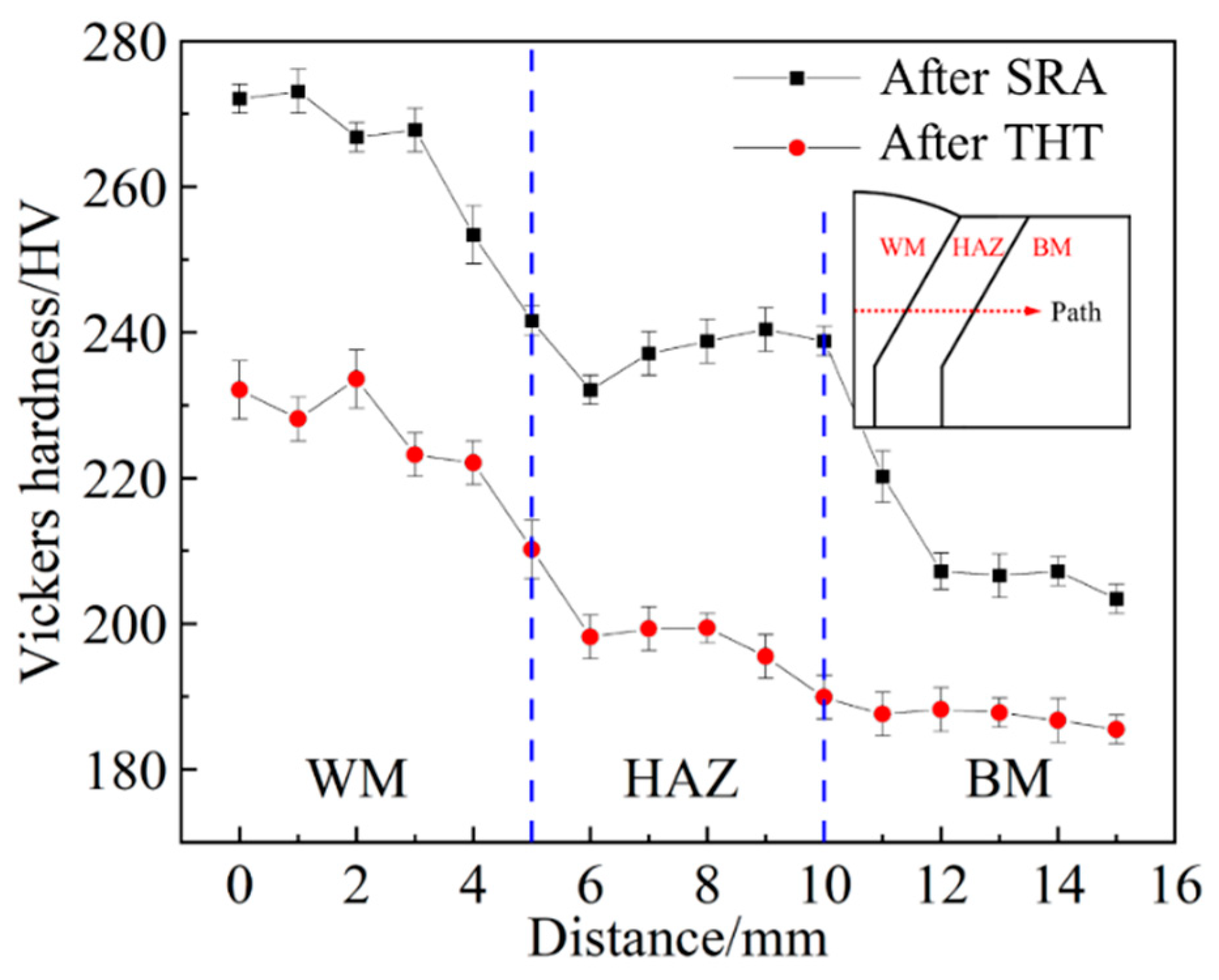
3.2. Evolution of Microhardness

Figure 8 illustrates the distribution of microhardness across the welded joints at stress relief annealing and tempering heat treatment conditions. it is clearly found that the overall trend is as follows: weld seam zone > heat-affected zone > base material zone. This difference in hardness is collectively reflected by variations in element content, microstructure, and grain size in different microzones of the welded joint. More precisely, the weld zone exhibits the highest microhardness due to the higher content of elements like Mn and Si, which play a major role in solid solution strengthening. In addition, the microstructure of the weld zone is mainly composed of bainite and ferrite, which also results in the highest microhardness. The heat-affected zone has a similar microstructure to the base metal zone but has relatively smaller grain sizes, resulting in greater hardness values. In addition, after the tempering heat treatment, there is a significant reduction in microhardness throughout the welded joint. The difference in hardness between different zones decreases, particularly between the heat-affected zone and the base metal zone. Combined with the microstructure observation in Section 3.1, it is suggested that the reduction in microhardness is mainly due to the partial decomposition of bainite and pearlite, the growth of lower-hardness ferrite and the formation of tempering structures.

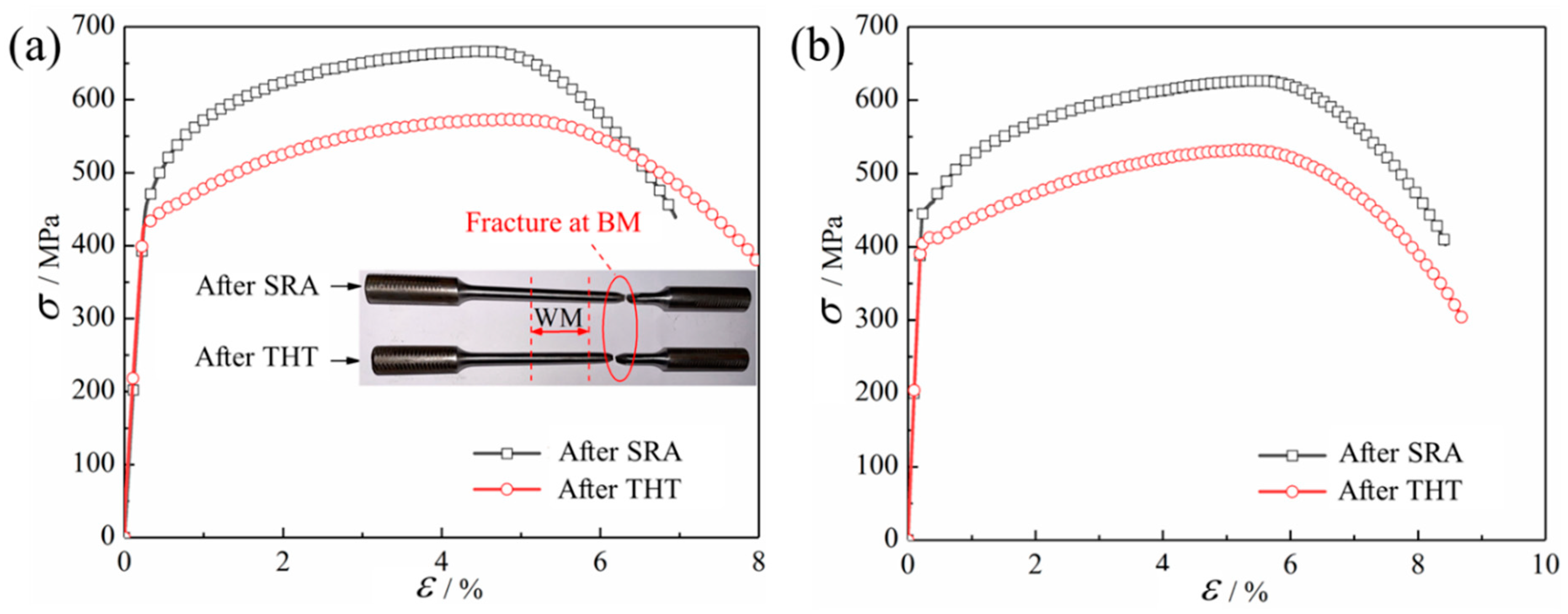
3.3. Evolution of Tensile Properties of Cross-Welded Joint by Standard Specimens

The tensile stress-strain curves obtained by standard specimen for the cross-welded joint and base material at room temperature are shown in Figure 9. Note that the final fracture occurred in the base material zone for the specimens at both stress relief annealing and tempering heat treatment conditions. There may be two reasons, i.e., first, the alloying elements in the welding rod are higher than those in the base metal (as shown in Table 1), indicating a high-strength match for the welding process. Second, the coarse-grained region in the heat-affected zone experiences alloy strengthening due to element diffusion from the weld metal, at the same time, the fine-grained zone, characterized by small and uniformly distributed grain sizes, contributes to fine-grain strengthening in the heat-affected zone. As a result, the overall strength of the heat-affected zone is higher than that of the base metal.
The quantitative strength values are listed in Table 4. It is clear that the strength of the welded joint significantly decreases after tempering heat treatment. The yield strength σy and ultimate tensile strength σu decrease by 12.3% and 13.7%, respectively, but the elongation increases. The behavior of the base metal specimens is consistent with that of the cross-weld joint specimens. After tempering heat treatment, the yield strength and ultimate strength of the base metal decreased by 8.8% and 15.4%, respectively. This is because tempering heat treatment results in the decomposition of some pearlite, leading to an increased proportion of ferrite, which has relatively lower strength but better ductility.

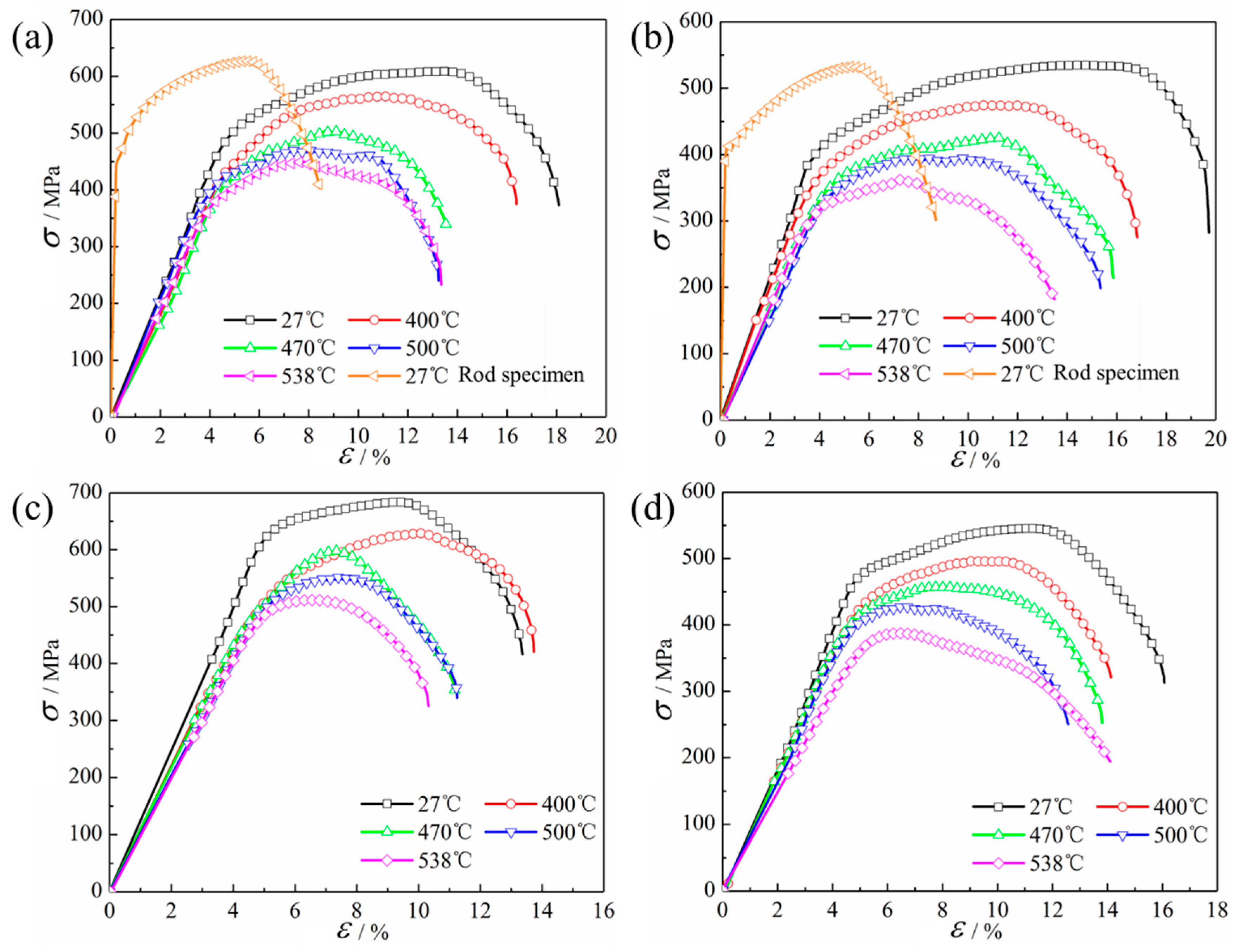
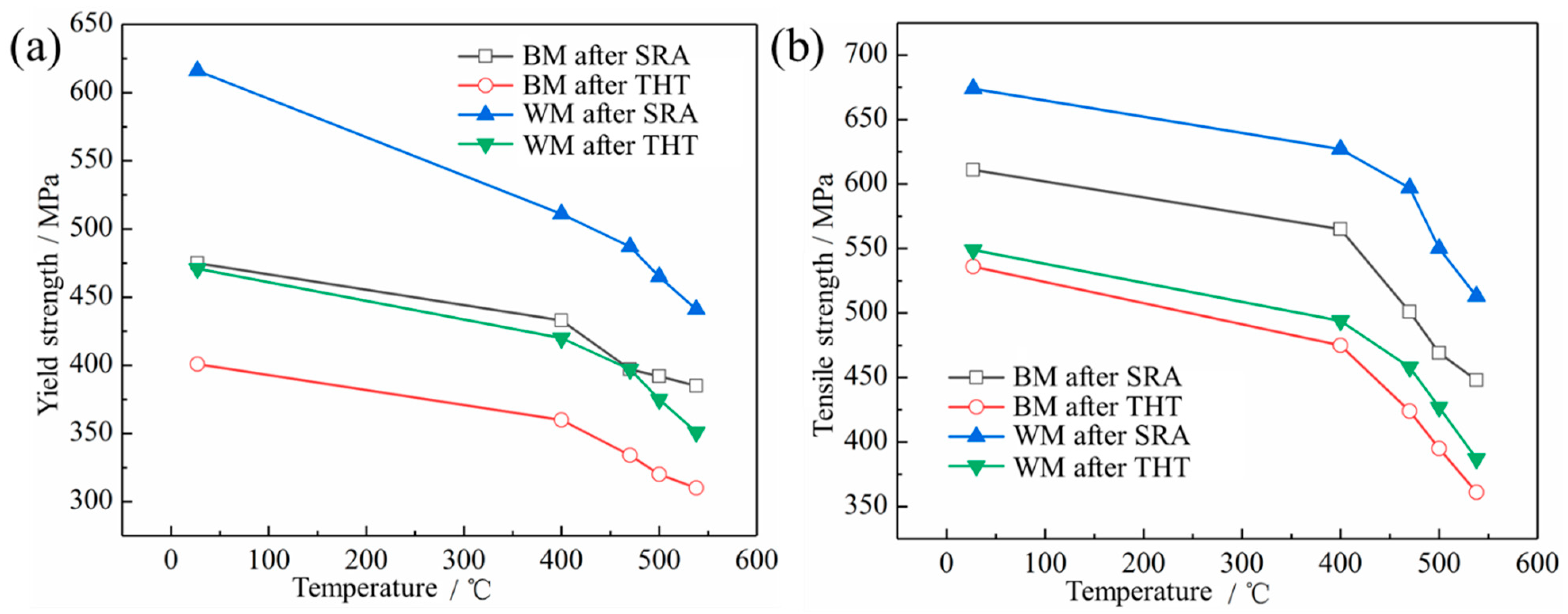
3.4. Evolution of Tensile Properties at Different Temperatures

Figure 10a,b displays the tensile curves at various temperatures for the base metal and cross-welded joints at the stress relief annealing and tempering heat treatment conditions. The room-temperature tensile curves obtained by standard specimens are also provided for comparison. It is evident that the elastic modulus of the micro-sized specimens is significantly lower than that obtained from the standard specimens. Research by Yang et al. [35] has shown that this difference is primarily caused by deformations and clamping effects induced by the fixtures and the insufficient stiffness during the tensile phase of micro-flat specimens. However, the yield strength and ultimate tensile strength of the micro-sized specimens are in great agreement with the results from standard specimens. Therefore, employing miniature specimens to characterize the strength of different regions of the welded joint is effective and feasible.
The middle parallel section of the miniature specimens consists entirely of the weld metal and is fractured in the weld metal zone. Therefore, the obtained performance can be considered as the tensile properties of the weld metal. Combined with Figure 11, it is evident that the yield strength and ultimate tensile strength of the weld metal are significantly higher than that of the base metal at the same temperature in both two conditions. This is consistent with the observed microhardness distribution patterns in different zones, and it is a result of the combined effects of differences in alloying element content, microstructure, and grain size between the weld metal and base metal. In addition, at all temperatures, the specimens after tempering heat treatment exhibit significantly lower yield strength and ultimate tensile strength. Specifically, the yield strength decreases by 15–20%, and the ultimate tensile strength decreases by 13–20%. However, the ductility of the base metal after tempering heat treatment is slightly enhanced.

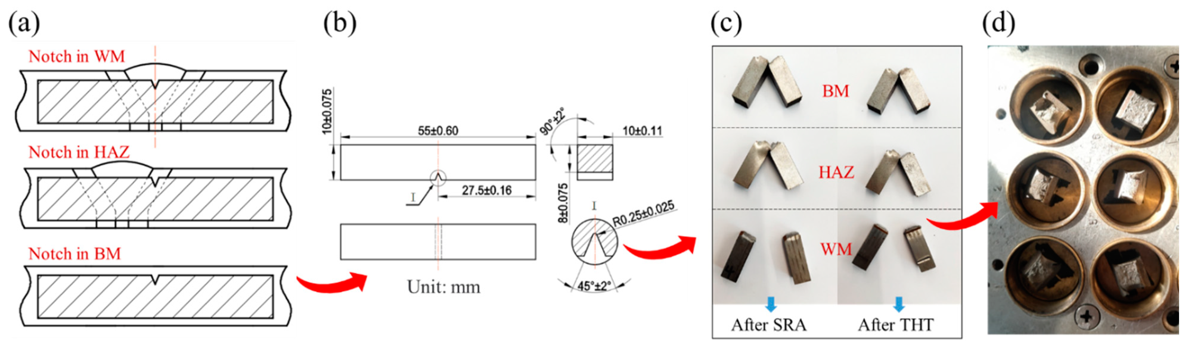
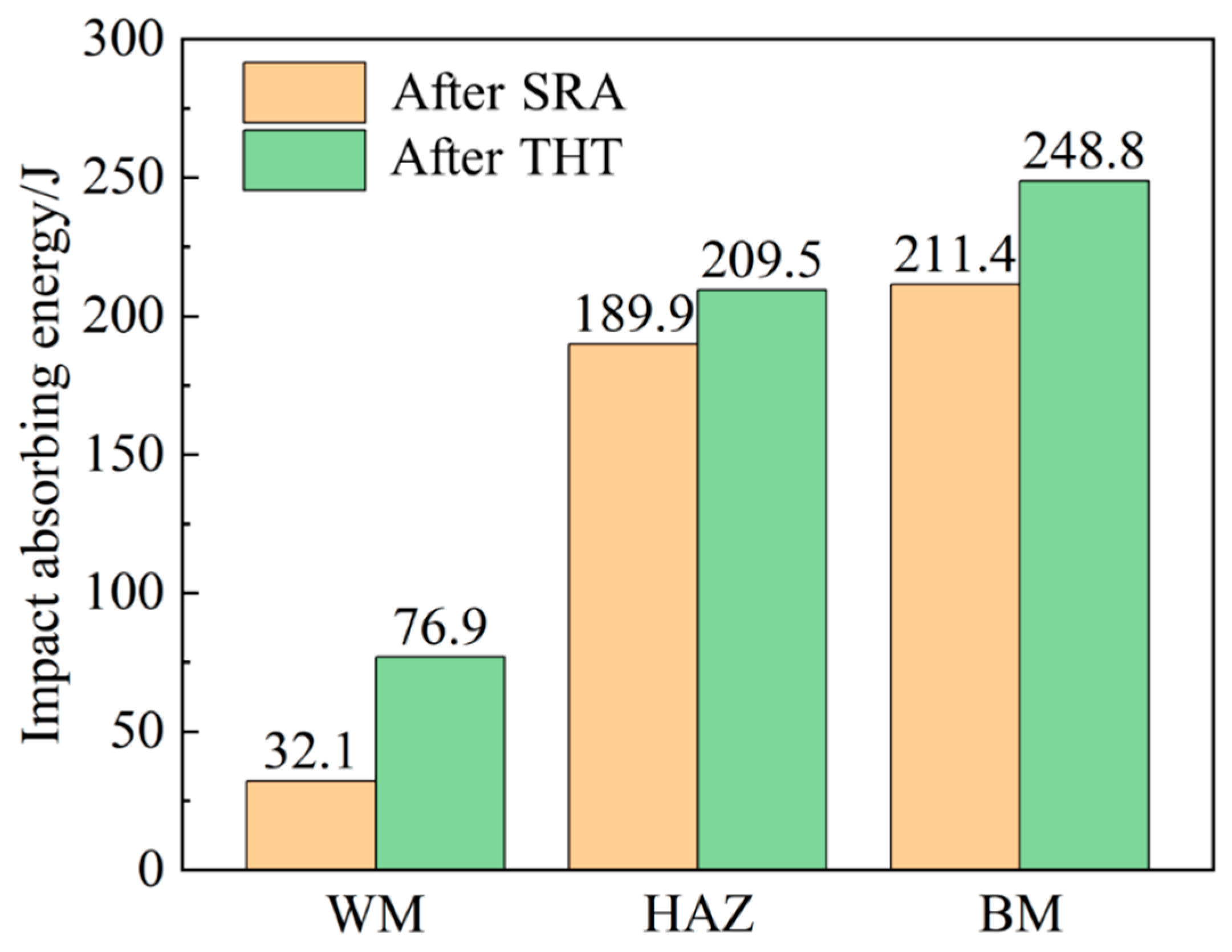
3.5. Evolution of Impact Properties

Figure 12 gives the evolution of impact absorption energy at different subzones of welded joints at the stress relief annealing and tempering heat treatment conditions. It is clearly found that the impact absorption energy follows the order of base metal > HAZ > weld metal. The higher impact toughness of the base metal can be attributed to its uniform microstructure consisting of ferrite and pearlite, with pearlite exhibiting better toughness than bainite. The HAZ has a more complex microstructure, resulting in slightly lower toughness, while the presence of bainite in the weld metal reduces its impact toughness. In addition, the values at tempering heat treatment conditions are greater than those at stress relief annealing conditions.
The fracture morphology is shown in Figure 13. Before tempering, both the base metal and HAZ have numerous dimples of varying sizes, depths, and shapes, indicating ductile fracture. The HAZ’s dimples are shallower than those in the base metal, resulting in slightly lower toughness. On the other hand, the weld metal fracture surface is relatively flat with minimal fibrous regions, showing characteristics of brittle cleavage fracture, suggesting lower toughness. After tempering, the macroscopic fracture surfaces in all three regions become rougher. The HAZ and base metal fractures show a similar pattern, with visible dimples, indicating enhanced toughness. In the weld metal, the fracture surface becomes significantly rougher and exhibits clear fibrous regions. Microscopically, the fracture surface shows characteristics of quasi-cleavage fracture with the presence of smaller dimples, indicating an overall fracture mode combining quasi-cleavage and dimples. Overall, tempering heat treatment increases the impact of toughness in all regions. In the HAZ and base metal, the partial decomposition of pearlite and grain growth in ferrite contribute to the enhanced toughness. The most significant enhancement is observed in the weld metal due to a significant reduction in coarsely coarsened bainite after tempering.

4. Concluding Remarks

This paper investigated the effect of post-weld heat treatment on the microstructure and mechanical properties of different subzones of 12Cr1MoV welded joints. The main conclusions are as follows:
(1)
After tempering heat treatment, there is a consistent change in the macro-mechanical performance of various subzones, i.e., the hardness and strength are reduced by 10–20%, but the ductility is increased, especially in the weld zone. The impact toughness in the weld zone is increased by 58.2%, which changes are primarily attributed to the significant reduction in the content of coarsely coarsening ferrite.
(2)
Regardless of heat treatment, the weld zone of the 12Cr1MoV joint always shows the lowest ductility among all micro-zones and is prone to brittle fracture in practical applications. In contrast, the heat-affected zone demonstrates relatively balanced performance, while the base metal exhibits lower tensile properties at both room temperature and high temperatures.
(3)
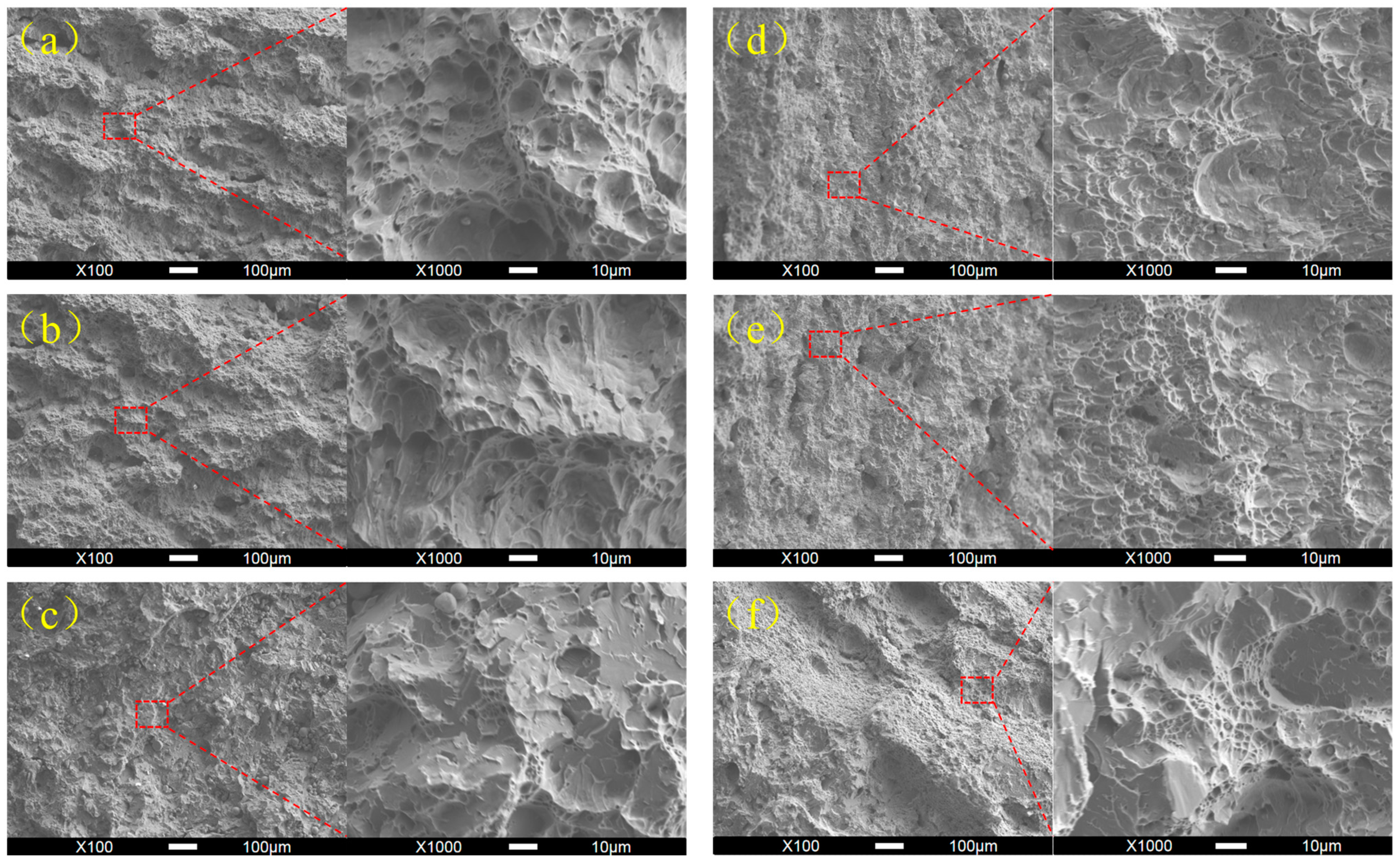
The enhancement in ductility in the weld zone is most significant after tempering heat treatment. Prior to heat treatment, the fracture mode in the weld zone is brittle cleavage. After heat treatment, the fracture mode shifts to quasi-cleavage and dimple-like ductile features. Therefore, tempering heat treatment can greatly enhance the toughness of the weld zone.
(4)
Hardness is found to be a suitable indicator to reflect changes in microstructure. Changes in strength show a positive correlation with hardness changes, while changes in ductility exhibit a negative correlation with hardness changes. Therefore, hardness testing can be used at engineering sites to assess the effectiveness of post-weld heat treatment in increasing welded joint properties.

Author Contributions

Conceptualization, B.Y. and G.S.; methodology B.Y.; software, G.S. and Z.L.; test, Z.L., G.S. and X.S.; data curation, G.S., X.S. and Z.L.; investigation, B.Y.; resources, X.H.; writing—original draft preparation, G.S., B.Y. and W.P.; writing—review and editing, B.Y., G.S., W.P. and X.X.; visualization, X.X.; supervision, X.H.; project administration, B.Y. and X.H.; funding acquisition, B.Y. All authors have read and agreed to the published version of the manuscript.

Funding

Supported by the National Natural Science Foundation of China (Grant No. 52275168).

Institutional Review Board Statement

Not applicable.

Informed Consent Statement

Not applicable.

Data Availability Statement

The data presented in this study are available in this article.

Conflicts of Interest

The authors declare no conflict of interest.

References

  1. Guo, Y.; Zhu, B.; Li, Z.; Wang, T.; Zhang, J.; Xiong, J.; Zhao, P. Research on the micro zone strength and strain hardening behavior in the 30Cr2Ni4MoV rotor welded joint. Mater. Sci. Eng. A 2023, 862, 144456. [Google Scholar] [CrossRef]
  2. Jovanović, M.; Čamagić, I.; Sedmak, S.; Sedmak, A.; Burzić, Z. Effect of material heterogeneity and testing temperature on fatigue behaviour of Cr-Mo steel welded joints. Eng. Fail. Anal. 2022, 141, 106542. [Google Scholar] [CrossRef]
  3. Thakare, J.G.; Pandey, C.; Gupta, A.; Taraphdar, P.K.; Mahapatra, M.M. Role of the heterogeneity in microstructure on the mechanical performance of the Autogenous Gas Tungsten Arc (GTA) welded dissimilar joint of F/M P91 and SS304L steel. Fusion Eng. Des. 2021, 168, 112616. [Google Scholar] [CrossRef]
  4. Gong, H.C.; Fan, Q.B.; Zhang, H.M.; Wang, D.D.; Yu, H.; Yang, L.; Zhu, X.J.; Wang, L. Effects of microstructure heterogeneity on tensile properties and failure mechanism of GTAW joint of as-cast Ti2531. Mater. Charact. 2022, 194, 112258. [Google Scholar] [CrossRef]
  5. Dak, G.; Pandey, C.A. A critical review on dissimilar welds joint between martensitic and austenitic steel for power plant application. J. Manuf. Process. 2020, 58, 377–406. [Google Scholar] [CrossRef]
  6. Wan, Y.; Jiang, W.C.; Song, M.; Huang, Y.L.; Li, J.; Sun, G.A.; Shi, Y.; Zhai, X.N.; Zhao, X.; Ren, L.C. Distribution and formation mechanism of residual stress in duplex stainless steel weld joint by neutron diffraction and electron backscatter diffraction. Mater. Des. 2019, 181, 108086. [Google Scholar] [CrossRef]
  7. Peng, W.; Jiang, W.C.; Sun, G.H.; Yang, B.; Shao, X.M.; Tu, S.T. Biaxial residual stress measurement by indentation energy difference method: Theoretical and experimental study. Int. J. Press. Vessel. Pip. 2022, 195, 104573. [Google Scholar] [CrossRef]
  8. Pandey, C.; Mahapatra, M.M.; Kumar, P.; Kumar, S.; Sirohi, S. Effect of post weld heat treatments on microstructure evolution and type IV cracking behavior of the P91 steel welds joint. J. Mater. Process. Technol. 2019, 266, 140–154. [Google Scholar] [CrossRef]
  9. Peng, W.; Jiang, W.C.; Yang, B.; Sun, G.H.; Shao, X.M. An indentation method for measuring welding residual stress: Estimation of stress-free indentation curve using BP neural network prediction model. Int. J. Press. Vessel. Pip. 2023, 206, 105070. [Google Scholar] [CrossRef]
  10. Kumar, R.; Varma, A.; Kumar, Y.R.; Neelakantan, S.; Jain, J. Enhancement of mechanical properties through modified post-weld heat treatment processes of T91 and Super304H dissimilar welded joint. J. Manuf. Process. 2022, 78, 59–70. [Google Scholar] [CrossRef]
  11. Guo, Y.; Li, Z.; Dong, Z.; Xiong, J.; Xu, J.; Xu, D.; Zhang, J. Influence of microstructure on the micro-region fracture toughness of the 30Cr2Ni4MoV turbine rotor welded joint. Int. J. Press. Vessel. Pip. 2023, 201, 104877. [Google Scholar] [CrossRef]
  12. Seo, W.G.; Suh, J.Y.; Shim, J.H.; Lee, H.; Yoo, K.; Choi, S.H. Effect of post-weld heat treatment on the microstructure and hardness of P92 steel in IN740H/P92 dissimilar weld joints. Mater. Charact. 2020, 160, 110083. [Google Scholar] [CrossRef]
  13. Tan, L.; Li, S.; Zhao, L.; Wang, L.; Zhao, X. The effect of mechanical inhomogeneity in microzones of welded joints on CTOD fracture toughness of nuclear thick-walled steel. Nucl. Eng. Technol. 2023, 55, 4112–4119. [Google Scholar] [CrossRef]
  14. Kromm, A.; Lausch, T.; Schröpfer, D.; Rhode, M.; Kannengießer, T. Influence of welding stresses on relief cracking during heat treatment of a creep-resistant 13CrMoV steel: Part I—Effect of heat control on welding stresses and stress relief cracking. Weld. World 2020, 64, 807–817. [Google Scholar] [CrossRef]
  15. Xie, P.; Zhao, H.; Wu, B.; Gong, S. Evaluation of Residual Stresses Relaxation by Post Weld Heat Treatment Using Contour Method and X-ray Diffraction Method. Exp. Mech. 2015, 55, 1329–1337. [Google Scholar] [CrossRef]
  16. Wang, Z.L. Control of microstructure and properties of welded joints of heavy structures of low alloy high strength steels. Key Eng. Mater. 2019, 814, 171–175. [Google Scholar] [CrossRef]
  17. Rhode, M.; Nietzke, J.; Richter, T.; Mente, T.; Mayr, P.; Nitsche, A. Hydrogen effect on mechanical properties and cracking of creep-resistant 9% Cr P92 steel and P91 weld metal. Weld. World 2023, 67, 183–194. [Google Scholar] [CrossRef]
  18. Du, C.; Wang, X.; Luo, C. Effect of post-weld heat treatment on the microstructure and mechanical properties of the 2205DSS/Q235 laser beam welding joint. J. Mater. Process. Technol. 2019, 263, 138–150. [Google Scholar] [CrossRef]
  19. Schönmaier, H.; Fleißner-Rieger, C.; Krein, R.; Schmitz-Niederau, M.; Schnitzer, R. On the impact of post weld heat treatment on the microstructure and mechanical properties of creep resistant 2.25 Cr–1Mo–0.25 V weld metal. J. Mater. Sci. 2021, 56, 20208–20223. [Google Scholar] [CrossRef]
  20. Khalaj, G.; Pouraliakbar, H.; Jandaghi, M.R.; Gholami, A. Microalloyed steel welds by HF-ERW technique: Novel PWHT cycles, microstructure evolution and mechanical properties enhancement. Int. J. Press. Vessel. Pip. 2017, 152, 15–26. [Google Scholar] [CrossRef]
  21. Dey, H.C.; Albert, S.K.; Bhaduri, A.K.; Roy, G.G.; Balakrishnan, R.; Panneerselvi, S. Effect of post-weld heat treatment (PWHT) time and multiple PWHT on mechanical properties of multi-pass TIG weld joints of modified 9Cr-1Mo steel. Weld. World 2014, 58, 389–395. [Google Scholar] [CrossRef]
  22. Sun, Q.; Li, X.; Li, K.; Cai, Z.; Han, C.; Li, S.; Pan, J. Effects of long-term service on microstructure and impact toughness of the weld metal and heat-affected zone in CrMoV steel joints. Metals 2022, 12, 278. [Google Scholar] [CrossRef]
  23. Tomerlin, D.; Marić, D.; Kozak, D.; Samardžić, I. Post-Weld Heat Treatment of S690QL1 Steel Welded Joints: Influence on Microstructure, Mechanical Properties and Residual Stress. Metals 2023, 13, 999. [Google Scholar] [CrossRef]
  24. Taheri, M.; Halvaee, A.; Kashani-Bozorg, S.F. Effect of Pre- and Post-weld Heat Treatment on Microstructure and Mechanical Properties of GTD-111 Superalloy Welds. Met. Mater. Int. 2021, 27, 1173–1192. [Google Scholar] [CrossRef]
  25. Kromm, A.; Lausch, T.; Schröpfer, D.; Rhode, M.; Kannengießer, T. Influence of welding stresses on relief cracking during heat treatment of a creep-resistant 13CrMoV steel part II: Mechanisms of stress relief cracking during post weld heat treatment. Weld. World 2020, 64, 819–829. [Google Scholar] [CrossRef]
  26. Chen, Z.M. Comparative analysis of hydrogen and stress relief heat treatment of welded joint of SUMITEN610F-TMC steel. Mech. Electr. Tech. Hydropower Stn. 2016, 39, 49–52, 61. [Google Scholar] [CrossRef]
  27. Zhang, S.M.; Tang, C.P.; Wang, P.; Sun, Z.Q.; Zhou, L.; Zhang, Y.; Jiang, D.Y.; Lü, Y.S.; Chen, Z.B. Analysis on welding crack of 12Cr1MoV steel water wall and its countermeasures. Heat Treat. Met. 2016, 41, 180–184. [Google Scholar] [CrossRef]
  28. Zhang, C.Z.; Yang, S.H.; Gong, B.M.; Deng, C.Y.; Wang, D.P. Effects of post weld heat treatment (PWHT) on mechanical properties of C-Mn weld metal: Experimental observation and microstructure-based simulation. Mater. Sci. Eng. A 2018, 712, 430–439. [Google Scholar] [CrossRef]
  29. Jiang, F.; Zhao, J.; Jian, H.G.; He, Z.B.; Lei, X.F. Influence of post-weld heat treatment on microstructures and mechanical properties of welded joints for al-mg-sc alloy sheets. Acta Metall. Sin. 2008, 10, 1277–1280. [Google Scholar] [CrossRef]
  30. Wang, J.J.; Sun, J.; Yu, X.H.; Chen, G.C.; Fu, Q.H.; Gao, C.; Tang, W.M. Microstructures and mechanical properties of 12cr1movg tube welded joints with/without post-weld heat treatment. J. Mater. Eng. Perform. 2017, 26, 4659–4666. [Google Scholar] [CrossRef]
  31. GB/T 2651-2008; Tensile Test Method on Welded Joints. GB/T: Beijing, China, 2008.
  32. GB/T 228.1-2010; Metallic Materials-Tensile Testing—Part 1: Method of Test at Room Temperature. GB/T: Beijing, China, 2010.
  33. GB/T 229-2007; Metallic Materials Charpy Pendulum Impact Test Method. GB/T: Beijing, China, 2007.
  34. GB/T 2650-2008; Impact Test Methods on Welded Joints. GB/T: Beijing, China, 2007.
  35. Yang, B.; Sun, W.Q.; Jiang, W.C.; Wang, M.L.; Li, M.C.; Chen, J.K. Comparative study of the tensile properties of a 1.25Cr-0.5Mo steel characterized by the miniature specimen and the standard specimen. Int. J. Press. Vessel. Pip. 2019, 177, 103990. [Google Scholar] [CrossRef]
Figure 1. (a) Pre-weld preheating and groove profile, (b) configuration of welded joints, and (c) post-weld heat treatment process: stress relief annealing (SRA) and tempering heat treatment (THT).
Metals 13 01998 g001
Figure 2. Microstructure observation test: (a) Sampling position of the metallographic sample, (b) inverted metallographic microscope, and (c) overall appearance of welded joint.
Metals 13 01998 g002
Figure 3. Micro-hardness test: (a) microvickers hardness tester, (b) indentation morphology, and (c) testing paths.
Metals 13 01998 g003
Figure 4. Tensile test at room temperature: (a) sampling diagram of rod-shaped tensile specimen, (b) size of the tensile specimens, and (c) tensile testing process.
Metals 13 01998 g004
Figure 5. High-temperature tensile test for miniature plate: (a) sampling diagram of miniature plate tensile specimen, (b) miniature plate sample size, and (c) testing process.
Metals 13 01998 g005
Figure 6. Impact test and fractography observation: (a) sampling position of impact specimen, (b) size of Charpy impact sample, (c) fracture of impact specimen, and (d) fracture samples.
Metals 13 01998 g006
Figure 7. Microstructure after stress relief annealing for (a) weld metal zone, (b) fusion zone, (c) fine grain heat-affected zone, (d) base metal zone and after tempering heat treatment for (e) weld metal zone, (f) fusion zone (g) fine grain heat-affected zone, and (h) base metal zone.
Metals 13 01998 g007
Figure 8. Distribution of microhardness across the welded joints at stress relief annealing and tempering heat treatment conditions.
Metals 13 01998 g008
Figure 9. Tensile stress-strain curves for (a) cross-welded joint and (b) base metal.
Metals 13 01998 g009
Figure 10. Tensile stress-strain curves at different temperatures for (a) annealing base metal, (b) tempering base metal, (c) annealing cross-welded joints, and (d) tempering cross-welded joints.
Metals 13 01998 g010
Figure 11. Variation of tensile properties with temperature for (a) yield strength and (b) tensile strength.
Metals 13 01998 g011
Figure 12. Impact absorption energy at different subzones of the welded joint.
Metals 13 01998 g012
Figure 13. Impact fracture morphology of (a) annealing weld metal, (b) annealing heat-affected zone, (c) annealing base metal, (d) tempering weld metal, (e) tempering heat-affected zone, and (f) tempering base metal.
Metals 13 01998 g013
Table 1. The chemical composition of base and filler metal (wt, %).
MaterialFeCMnSiCrMoVSP
12Cr1MoVBalance0.130.550.341.080.310.230.0180.017
R317Balance0.120.900.601.500.650.350.0200.020
Table 2. Welding process parameters.
Weld PassCurrent (A)Voltage (V)Time (s)Cooling Time (s)Heat Input (kJ/mm)Electrode Diameter (mm)
11502210011000.4383.2
2120221207800.4183.2
3140251157850.5254.0
4140251309000.5834.0
5140251409100.6284.0
615025145Cooled to 120 °C0.6754.0
Table 3. Post-weld heat treatment process parameters.
Heat Treatment ProcessInitial
Temperature
Holding TemperatureHolding TimeHeating RateCooling RateCooling Method
Stress Relief
Annealing
120 °C350 °C2 hUnrestrictedUnrestrictedAir-cooled
Tempering Heat Treatment30 °C730 °C1.5 h<300 °C:
Unrestricted
≥300 °C: ≤90 °C/h
<300 °C:
Unrestricted
≥300 °C: ≤65 °C/h
Furnace cooling
Table 4. Quantitative tensile properties of cross-welded joint and base metal.
Heat Treatment Conditionσy/MPaσu/MPaE/GPa
Annealing cross-welded joints487665211
Tempered cross-welded joints427574202
Annealing base metal455629205
Tempered base metal415532208
Disclaimer/Publisher’s Note: The statements, opinions and data contained in all publications are solely those of the individual author(s) and contributor(s) and not of MDPI and/or the editor(s). MDPI and/or the editor(s) disclaim responsibility for any injury to people or property resulting from any ideas, methods, instructions or products referred to in the content.

