
Influence of In Situ Magnetic Field on Magnetic Properties of a Bonded Permanent Magnet Manufactured through Material Extrusion Additive Manufacturing

Abstract
:1. Introduction
2. Materials and Methods
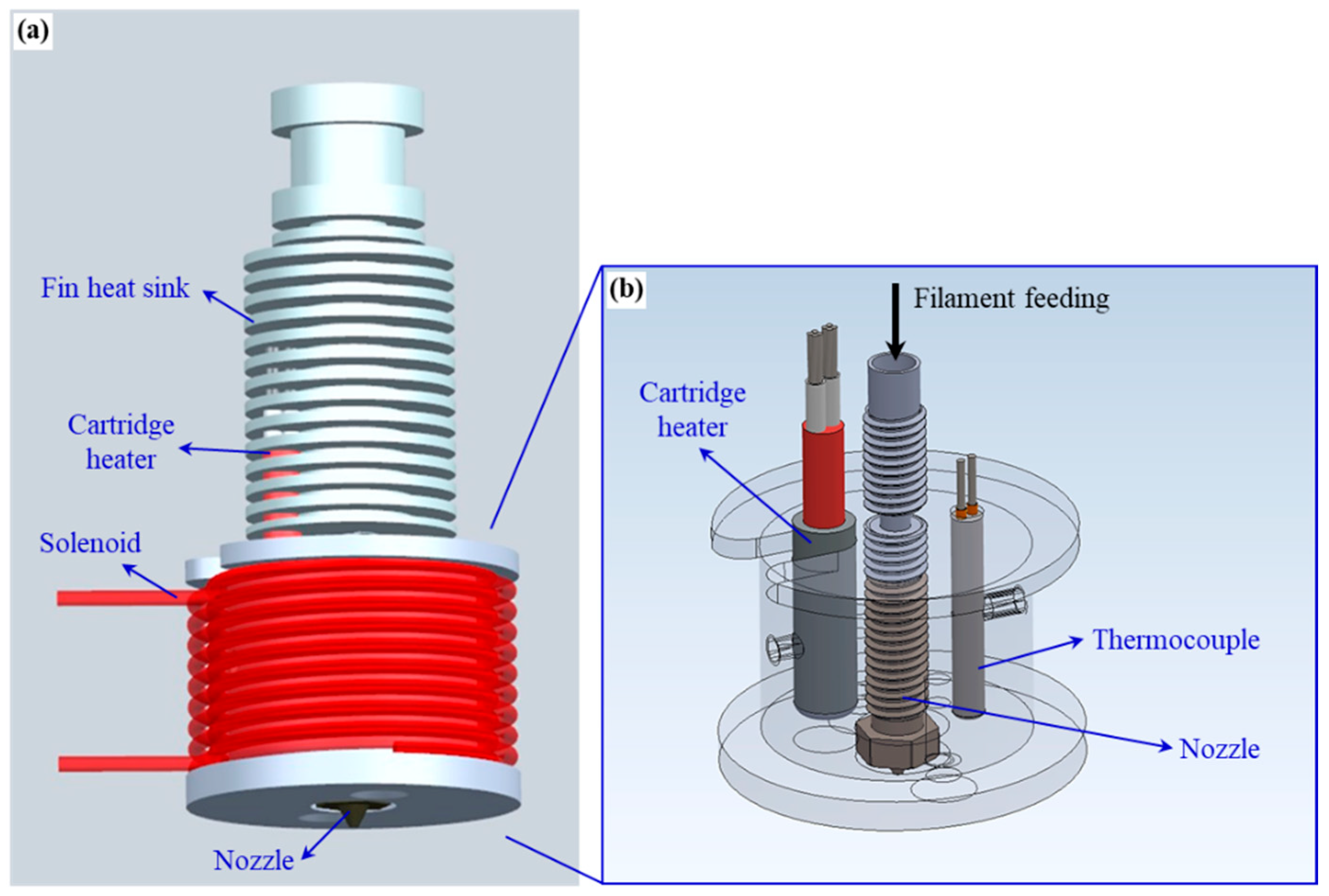
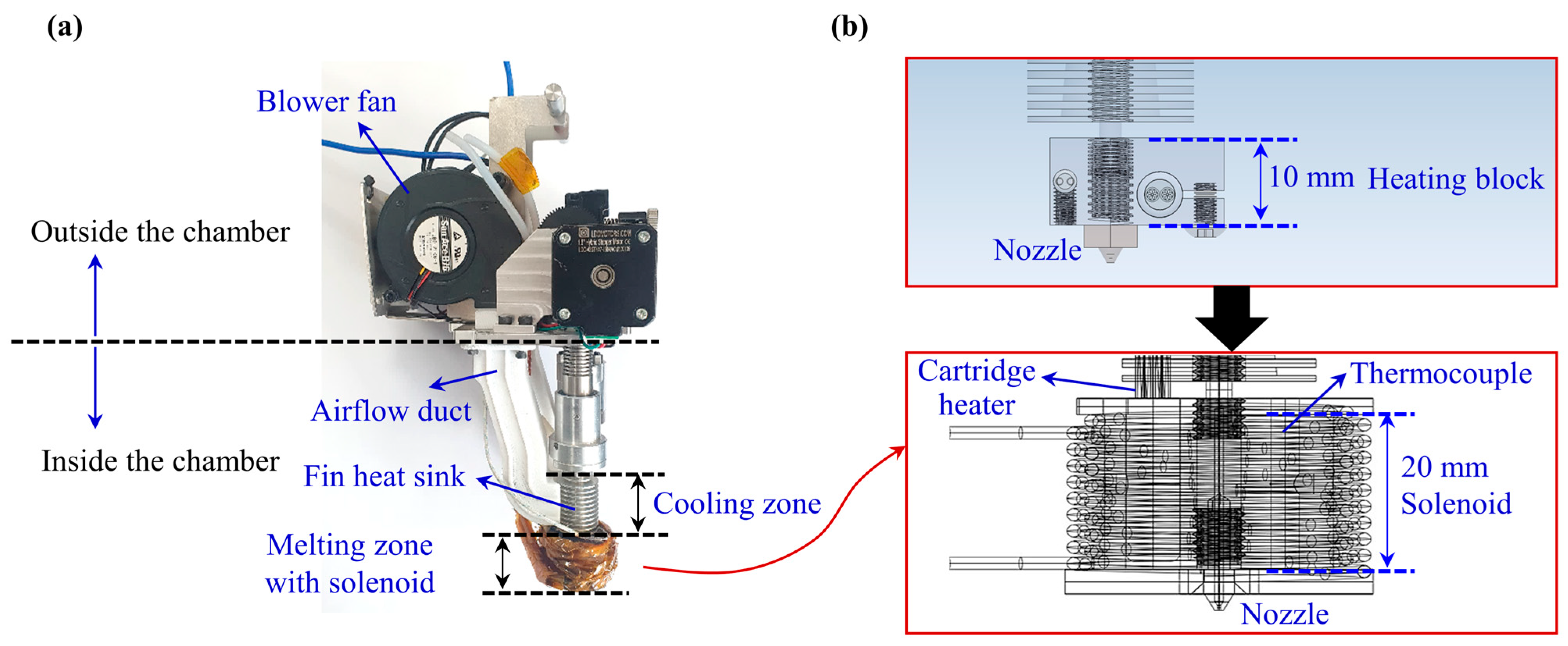
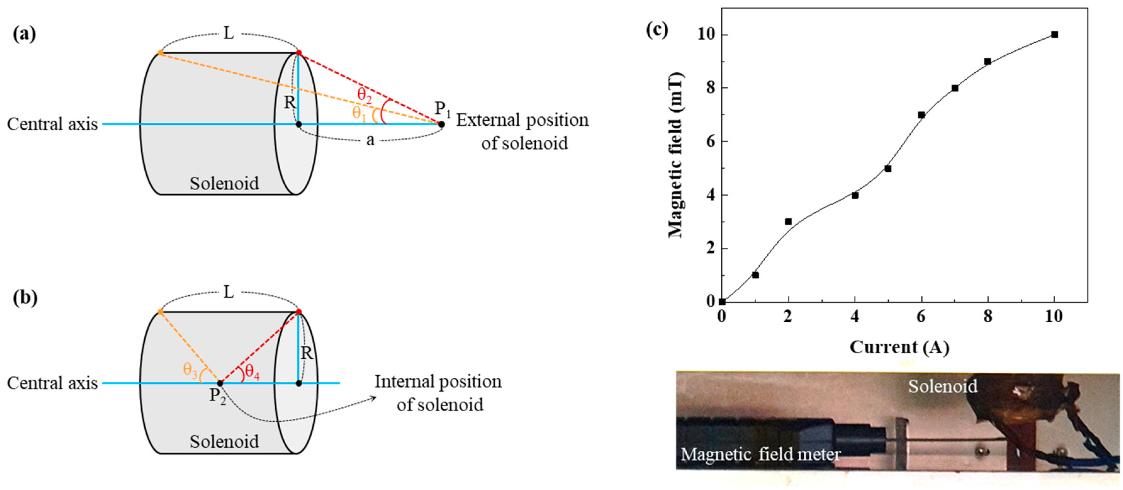
2.1. Nozzle with a Magnetic Field Application System
2.2. MEX Process and Property Analysis
3. Results and Discussion
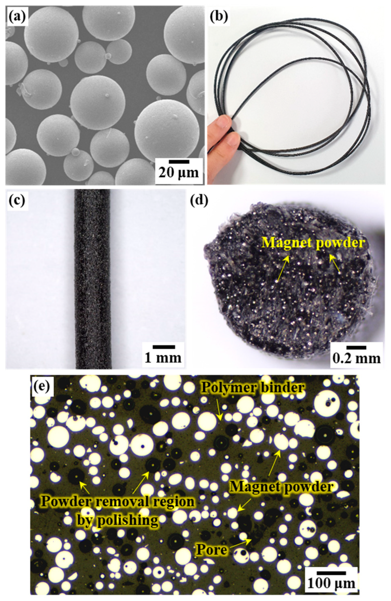
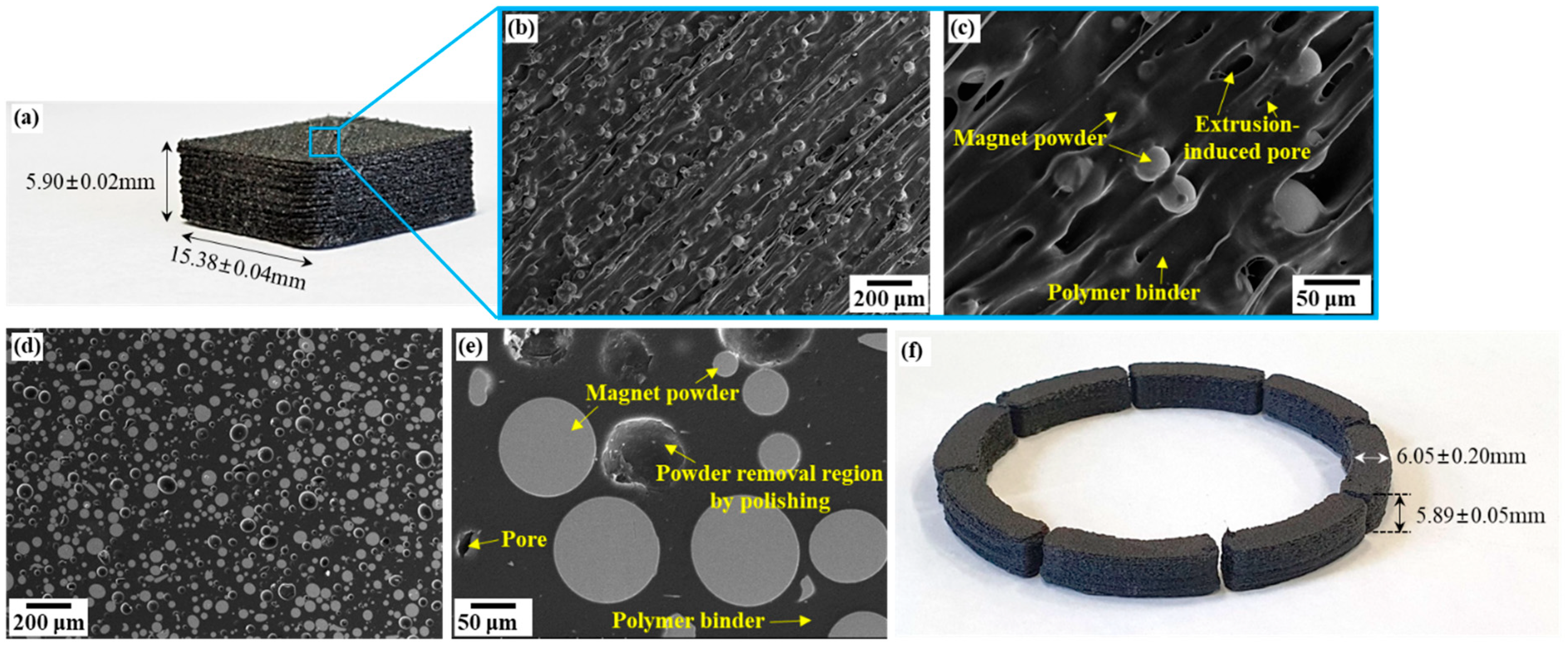
3.1. Fabrication of the Bonded Magnet
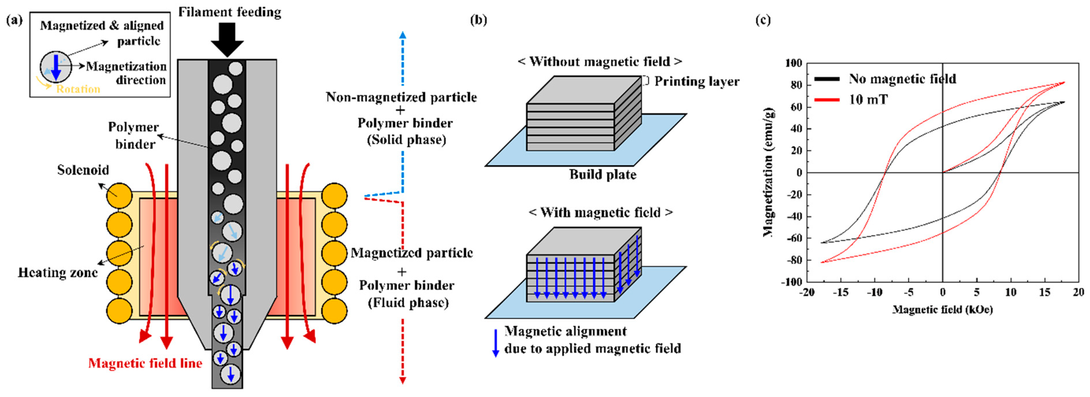
3.2. Magnetic Properties of MEX-Manufactured Bonded Magnets with In Situ Magnetic Field Application
- (1)
- Magnetic torque: This torque causes the rotation and alignment of magnetic particles under the influence of a magnetic field.
- (2)
- Drag torque: This torque hinders the rotation of magnetic particles and depends on the relative angular velocity between the fluid phase and the magnetic particles.
- (3)
- Particle-to-particle interaction torque: This torque is caused by the interaction between neighboring magnetic particles and can either support or oppose alignment, depending on the magnetic moment vectors of the particles. This interaction is called magnetostatic interaction.
4. Conclusions
Author Contributions
Funding
Data Availability Statement
Conflicts of Interest
References
- Pigliaru, L.; Paleari, L.; Bragaglia, M.; Nanni, F.; Ghidini, T.; Rinaldi, M. Poly-ether-ether-ketone—Neodymium-iron-boron bonded permanent magnets via fused filament fabrication. Synth. Met. 2021, 279, 116857. [Google Scholar] [CrossRef]
- Cao, Y.; Zhu, M.; Rong, M.Z.; Zhang, M.Q. Injection moldable, self-healable, and recyclable rubber-bonded NdFeB magnets with the magnetic particulates content up to 90 wt%. Adv. Compos. 2023, 6, 38. [Google Scholar] [CrossRef]
- Qu, Z.; Wu, Q.; Zhang, M.; Yue, M.; Liu, W. Facile preparation of bonded NdFeB/SmFeN hybrid magnets with flexibility, anisotropy and high energy density. J. Magn. Magn. Mater. 2023, 584, 171084. [Google Scholar] [CrossRef]
- Mungale, K.; Lamichhane, T.N.; Wang, H.; Sales, B.C.; Paranthaman, M.P.; Vaidya, U.K. Compression molding of anisotropic NdFeB bonded magnets in a polycarbonate matrix. Materials 2021, 19, 101167. [Google Scholar]
- Magnet Manufacturing Process. Available online: https://www.arnoldmagnetics.com/resources/magnet-manufacturing-process/ (accessed on 21 September 2023).
- Injection Molded Magnet. Available online: https://www.magnet-sdm.com/injection-molded-magnet/ (accessed on 21 September 2023).
- Li, L.; Jones, K.; Sales, B.; Pries, J.L.; Nlebedim, I.C.; Jin, K.; Bei, H.; Post, B.K.; Kesler, M.S.; Rios, O.; et al. Fabrication of highly dense isotropic Nd-Fe-B nylon bonded magnets via extrusion-based additive manufacturing. Addit. Manuf. 2018, 21, 495–500. [Google Scholar] [CrossRef]
- Petersdorff-Campen, K.; Hauswirth, Y.; Carpenter, J.; Hagmann, A.; Boës, S.; Daners, M.S.; Penner, D.; Meboldt, M. 3D printing of functional assemblies with integrated polymer-bonded magnets demonstrated with a prototype of a rotary blood pump. Appl. Sci. 2018, 8, 1275. [Google Scholar] [CrossRef]
- Slapnik, J.; Pulko, I.; Rudolf, R.; Anžel, I.; Brunčko, M. Fused filament fabrication of Nd-Fe-B bonded magnets: Comparison of PA12 and TPU matrices. Addit. Manuf. 2021, 38, 101745. [Google Scholar] [CrossRef]
- Li, L.; Tirado, A.; Nlebedim, I.C.; Rios, O.; Post, B.; Kunc, V.; Lowden, R.R.; Lara-Curzio, E.; Fredette, R.; Ormerod, J.; et al. Big area additive manufacturing of high performance bonded NdFeB magnets. Sci. Rep. 2016, 6, 36212. [Google Scholar] [CrossRef]
- Paranthaman, M.P.; Yildirim, V.; Lamichhane, T.N.; Begley, B.A.; Post, B.K.; Hassen, A.A.; Sales, B.C.; Gandha, K.; Nlebedim, I.C. Additive manufacturing of isotropic NdFeB PPS bonded permanent magnets. Materials 2020, 13, 3319. [Google Scholar] [CrossRef]
- Huber, C.; Abert, C.; Bruckner, F.; Groenefeld, M.; Muthsam, O.; Schuschnigg, S.; Sirak, K.; Thanhoffer, R.; Teliban, I.; Vogler, C.; et al. 3D print of polymer bonded rare-earth magnets, and 3D magnetic field scanning with an end-user 3D printer. Appl. Phys. Lett. 2016, 109, 162401. [Google Scholar] [CrossRef]
- Azimi, G.; Sauber, M.E.; Zhang, J. Technoeconomic analysis of supercritical fluid extraction process for recycling rare earth elements from neodymium iron boron magnets and fluorescent lamp phosphors. J. Clean. Prod. 2023, 422, 138526. [Google Scholar] [CrossRef]
- Delette, G. Nd2Fe14B permanent magnets substituted with non-critical light rare earth elements (Ce, La): A review. J. Magn. Magn. Mater. 2023, 577, 170768. [Google Scholar] [CrossRef]
- An, S.; Ma, Z.; Li, W.; Zhang, H.; Yin, T. Magnetic properties of anisotropic bonded NdFeB/SmCo permanent magnets. AIP Adv. 2019, 9, 125146. [Google Scholar] [CrossRef]
- Gao, R.W.; Zhang, J.C.; Zhang, D.H.; Dai, Y.Y.; Meng, X.H.; Wang, Z.M.; Zhang, Y.J.; Liu, H.Q. Dependence of the magnetic properties on the alignment magnetic field for NdFeB bonded magnets made from anisotropic HDDR powders. J. Magn. Magn. Mater. 1999, 191, 97–100. [Google Scholar] [CrossRef]
- Wang, H.; Lamichhane, T.N.; Paranthaman, M.P. Review of additive manufacturing of permanent magnets for electrical machines: A prospective on wind turbine. Mater. Today Phys. 2022, 24, 100675. [Google Scholar] [CrossRef]
- Gandha, K.; Li, L.; Nlebedim, I.C.; Post, B.K.; Kunc, V.; Sales, B.C.; Bell, J.; Paranthaman, M.P. Additive manufacturing of anisotropic hybrid NdFeB-SmFeN nylon composite bonded magnets. J. Magn. Magn. Mater. 2018, 467, 8–13. [Google Scholar] [CrossRef]
- Suppan, M.; Huber, C.; Mathauer, K.; Abert, C.; Brucker, F.; Gonzalez-Gutierrez, J.; Schuschnigg, S.; Groenefeld, M.; Teliban, I.; Kobe, S.; et al. In situ alignment of 3D printed anisotropic hard magnets. Sci. Rep. 2022, 12, 17590. [Google Scholar] [CrossRef]
- Sarkar, A.; Paranthaman, M.P.; Nlebedim, I.C. In-situ magnetic alignment model for additive manufacturing of anisotropic bonded magnets. Addit. Manuf. 2021, 46, 102096. [Google Scholar] [CrossRef]
- Sonnleitner, K.; Huber, C.; Teliban, I.; Kobe, S.; Saje, B.; Kagerbauer, D.; Reissner, M.; Lengauer, C.; Groenefeld, M.; Suess, D. 3D printing of polymer-bonded anisotropic magnets in an external magnetic field and by a modified production process. Appl. Phys. Lett. 2020, 116, 092403. [Google Scholar] [CrossRef]
- Nagarajan, B.; Aguilera, A.F.E.; Wiechmann, M.; Qureshi, A.J.; Mertiny, P. Characterization of magnetic particle alignment in photosensitive polymer resin: A preliminary study for additive manufacturing processes. Addit. Manuf. 2018, 22, 528–536. [Google Scholar] [CrossRef]
- Jung, H.Y.; Choi, K.S.; Hwang, J.Y. Nozzle Assembly, Three-Dimensional Printer and Three-Dimensional Printing Method Including the Same, and Electronic Component Case Manufactured Using the Same. International Patent System PCT/KR2022/019041, 29 November 2022. [Google Scholar]
- Park, S.J.; Lee, J.E.; Park, J.Y.; Lee, N.K.; Son, Y.; Park, S.H. High-temperature 3D printing of polyetheretherketone products: Perspective on industrial manufacturing applications of super engineering plastics. Mater. Des. 2021, 211, 110163. [Google Scholar] [CrossRef]
- Sarkara, A.; Somashekara, M.A.; Paranthaman, M.P.; Kramer, M.; Haase, C.; Nlebedim, I.C. Functionalizing magnet additive manufacturing with in-situ magnetic field source. Addit. Manuf. 2020, 34, 101289. [Google Scholar] [CrossRef]
- Nlebedim, I.C.; Ucar, H.; Hatter, C.B.; McCallum, R.W.; McCall, S.K.; Kramer, M.J.; Paranthaman, M.P. Studies on in situ magnetic alignment of bonded anisotropic Nd-Fe-B alloy powders. J. Magn. Magn. Mater. 2017, 422, 168–173. [Google Scholar] [CrossRef]
- Khazdozian, H.A.; Li, L.; Paranthaman, M.P.; McCall, S.K.; Kramer, M.J.; Nlebedim, I.C. Low-field alignment of anisotropic bonded magnets for additive manufacturing of permanent magnet motors. JOM 2019, 71, 626–632. [Google Scholar] [CrossRef]
- Kim, Y.H.; Yuk, H.W.; Zhao, R.; Chester, S.A.; Zhao, X. Printing ferromagnetic domains for untethered fast-transforming soft materials. Nature 2018, 558, 274–279. [Google Scholar] [CrossRef]


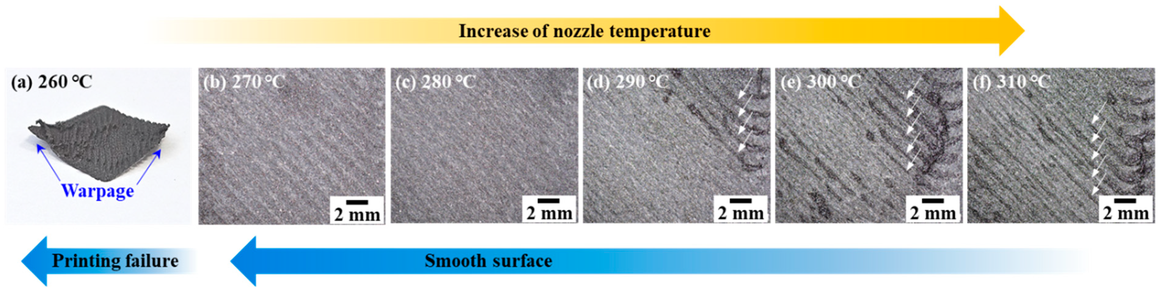
| Nozzle Temperature (°C) | 260–310 |
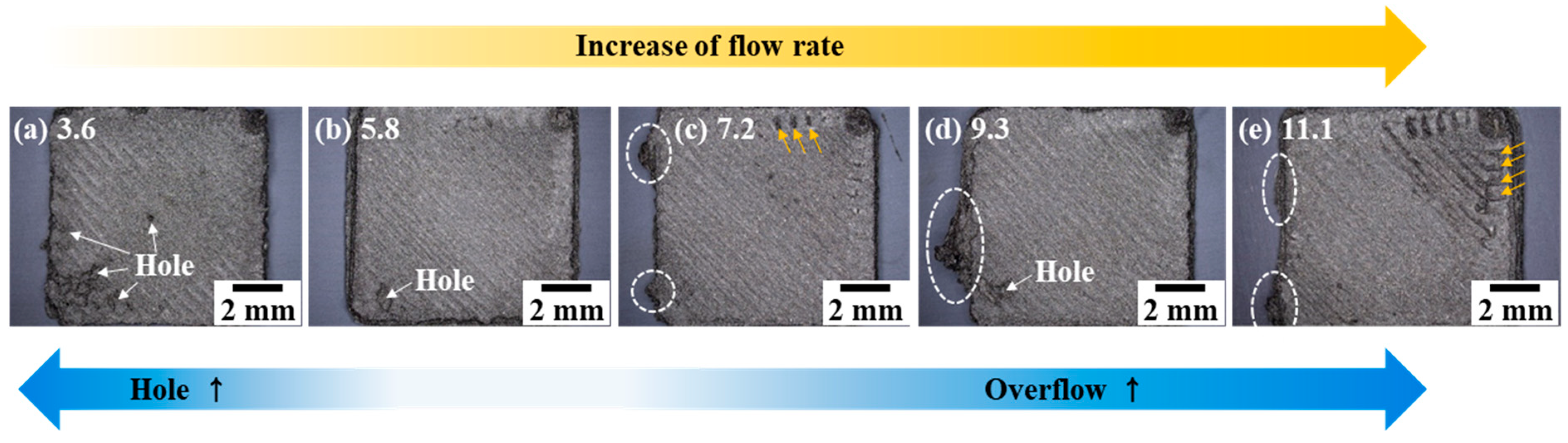
| Flow rate (mm3/s) | 3.6–11.1 |
| Printing speed (mm/s) | 2–10 |
| Magnetic field (mT) | 0, 10 |
| Layer thickness (mm) | 0.2 |
| Scan pattern | Zigzag pattern |
| Nozzle Temp. (°C) | ||||||
|---|---|---|---|---|---|---|
| 260 | 270 | 280 | 290 | 300 | 310 | |
| Protrusion by overflow | - | X | X | △ | ○ | ○ |
| Surface hole | - | X | X | X | X | X |
| Adhesion to the build plate | weak | weak | good | good | good | good |
| Warpage | ○ | △ | X | X | X | X |
| Roughness, Ra (μm) | - | 8.62 | 10.21 | 18.97 | 34.80 | 38.06 |
| Flow Rate (mm3/s) | |||||
|---|---|---|---|---|---|
| 3.6 | 5.8 | 7.2 | 9.3 | 11.1 | |
| Protrusion by overflow | X | X | △ | X | ○ |
| Surface hole | ○ | △ | X | △ | X |
| Adhesion to the build plate | good | good | good | good | good |
| Warpage | X | X | X | X | X |
| Roughness, Ra (μm) | 10.36 | 8.94 | 12.38 | 10.21 | 20.84 |
| Materials | Manufacturing Method | Magnetic Field (mT) | Magnetic Properties | |||||
|---|---|---|---|---|---|---|---|---|
| Initial Slope (emu/gOe) | Coercivity (Oe) | BHmax (kGOe) | Saturation Magnetization (emu/g) | Remanence (emu/g) | Mr/Ms | |||
| This study NdFeB +PA12 | MEX process under magnetic fields | 0 | 1.92 | 8305 | 853 | 65 | 42 | 0.64 |
| 10 | 2.72 | 8496 | 931 | 83 | 55 | 0.67 | ||
| [25] NdFeB/SmFeN +PA12 | MEX process under magnetic fields | 0 | - | 12,600 | - | - | - | 0.55 |
| 148–216 | - | 12,000 | - | - | - | 0.64 | ||
| [27] NdFeB +PA12 | Heating the manufactured bonded magnet for 15 min under magnetic fields | 0 | - | 12,750 | 1750 | - | - | 0.48 |
| 125 | - | 13,600 | 4000 | - | - | 0.70 | ||
| Material | Magnetic Field (mT) | Temperature (°C) | Manufacturing Method | Ref. | |
|---|---|---|---|---|---|
| Powder | Polymer Binder | ||||
| Anisotropic NdFeB alloy | Ethylene vinyl acetate | 1000–5000 | 50–130 | Heating the manufactured bonded magnet for 15 min under magnetic fields | [26] |
| Sm2Fe17N3 | PA12 | 100–200 | 300 | MEX process under a magnetic field | [21] |
| Sm2Fe17N3 | PA12 | 90–100 | 260 | MEX process under a magnetic field | [19] |
| Anisotropic NdFeB alloy | PA12 | 125–1000 | 220, 238, 256 | Heating the manufactured bonded magnet for 15 min under magnetic fields | [27] |
| Anisotropic NdFeB alloy | Mixture of two Silicone-based materials | 20–50 | - | Ink-jet printing under a magnetic field | [28] |
| NdFeB/SmFeN alloy | PA12 | 90–216 | 180–300 | MEX process under a magnetic field | [25] |
Disclaimer/Publisher’s Note: The statements, opinions and data contained in all publications are solely those of the individual author(s) and contributor(s) and not of MDPI and/or the editor(s). MDPI and/or the editor(s) disclaim responsibility for any injury to people or property resulting from any ideas, methods, instructions or products referred to in the content. |
© 2023 by the authors. Licensee MDPI, Basel, Switzerland. This article is an open access article distributed under the terms and conditions of the Creative Commons Attribution (CC BY) license (https://creativecommons.org/licenses/by/4.0/).
Share and Cite
Hwang, J.Y.; Park, S.J.; Son, Y.; Jung, H.Y. Influence of In Situ Magnetic Field on Magnetic Properties of a Bonded Permanent Magnet Manufactured through Material Extrusion Additive Manufacturing. Metals 2023, 13, 1653. https://doi.org/10.3390/met13101653
Hwang JY, Park SJ, Son Y, Jung HY. Influence of In Situ Magnetic Field on Magnetic Properties of a Bonded Permanent Magnet Manufactured through Material Extrusion Additive Manufacturing. Metals. 2023; 13(10):1653. https://doi.org/10.3390/met13101653
Chicago/Turabian StyleHwang, Ji Yong, Seong Je Park, Yong Son, and Hyo Yun Jung. 2023. "Influence of In Situ Magnetic Field on Magnetic Properties of a Bonded Permanent Magnet Manufactured through Material Extrusion Additive Manufacturing" Metals 13, no. 10: 1653. https://doi.org/10.3390/met13101653