

Vacuum Brazing and Performance Evaluation of T2 Copper Block and 316L Stainless Steel Tube

Science and Technology on Reactor Fuel and Materials Laboratory, Nuclear Power Institute of China, Chengdu 610225, China
*
Author to whom correspondence should be addressed.
Metals 2023, 13(8), 1349; https://doi.org/10.3390/met13081349
Submission received: 29 November 2022
/
Revised: 22 February 2023
/
Accepted: 13 March 2023
/
Published: 27 July 2023
(This article belongs to the Special Issue Mechanical Properties of Metals Welding Joints)
Abstract
:The International Thermonuclear Experiment Reactor (ITER) Thermal shield (TS) serves as a cryogenic heat exchanger to maintain the thermal stability of the ITER superconducting magnet coil, which is critical to the control of the plasma during the operation of the ITER device. The TS is composed of long-length 316L stainless steel (SS) and copper as brazed joints. In this case, a feasible fabrication design for the CCS TS is presented, accomplished by three kinds of joining processes (vacuum brazing, friction stir weld, and TIG weld). In the reliable fabrication design, the brazing quality of the as-brazed long-distance 316L SS and copper joints plays a critical role in the thermal conductivity performance of the ITER thermal shield. Therefore, a high-quality vacuum brazing process of long-length SS/Cu joints applied in a low-temperature superconductor magnet system was first studied. The macro metallography analysis demonstrates the braze ratio of the samples is 100%, and no crack or defect is observed in the samples. The microstructural characterization reveals the brazing seams are composed of silver-based Ag-rich eutectic. The micro-shear test indicates that the shear strength of the 316L tube and copper joint is 205 MPa, with the fracture position located on the copper side; this zone will be the most vulnerable zone of the joints. In addition, the SEM results illustrated that the shear fracture morphology displayed a ductile fracture feature. The test results demonstrated that the highly precise depth drilling employed in this paper ensured a good control of the brazing clearance, resulting in a 100% braze ratio for the long-length SS/Cu joints. Therefore, it can be concluded that the brazing process can be applied in the ITER TS for the good thermal conductivity performance of long-length SS/Cu-brazing joints.
1. Introduction
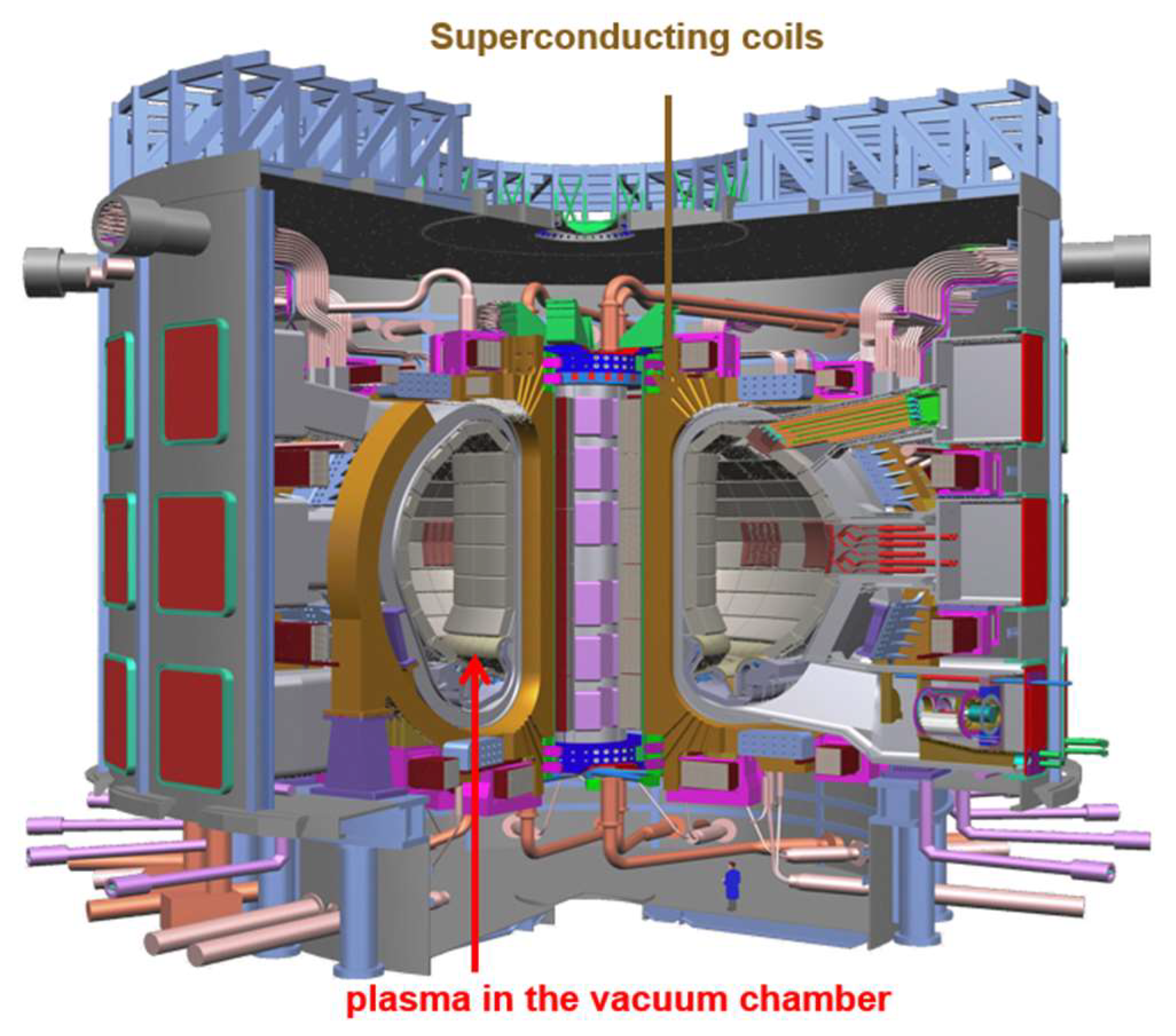
The International Thermonuclear Experiment Reactor (ITER) is the largest superconducting tokamak in the world to demonstrate the feasibility of power generation by nuclear fusion technology [1]. The ITER device, which is now under construction in the south of France, requires very large superconducting magnets for the confinement and control of the burning plasma [2,3]. This is to avoid damage to the first wall caused by the high-temperature plasma with a temperature of hundreds of millions of degrees. A superconduction magnet system is used to constrain the ultra-high temperature deuterium and tritium plasma in the ITER device. Therefore, the superconducting magnet system is an important component of the ITER machine as shown in Figure 1. The magnet system for ITER consists of 18 toroidal field (TF) coils, a central solenoid (CS), 6 poloidal field (PF) coils and 18 correction coils (CCs). In the ITER magnetic system, both the CS and TF coils operate at a high field and use a Nb3Sn-type superconductor. The PF coils and CCs use an NbTi superconductor. All coils are cooled with supercritical helium in the range of 4.4–4.7 K for the different magnet fields. The conductor, not illustrated here, is a cable-in-conduit conductor with a circular multistage cable consisting of about 1000 strands cabled around a small central cooling spiral tube. The operating currents are 40–45 kA for the CS and PF coils and 68 kA for the TF coils. The upper and lower CCs use a reduced-size conductor with about 300 strands and without the central cooling channel. The selection of the conductor operating temperature is linked to the choice of operating fields, the choice of superconductor technology and the design of the cryo-plant.
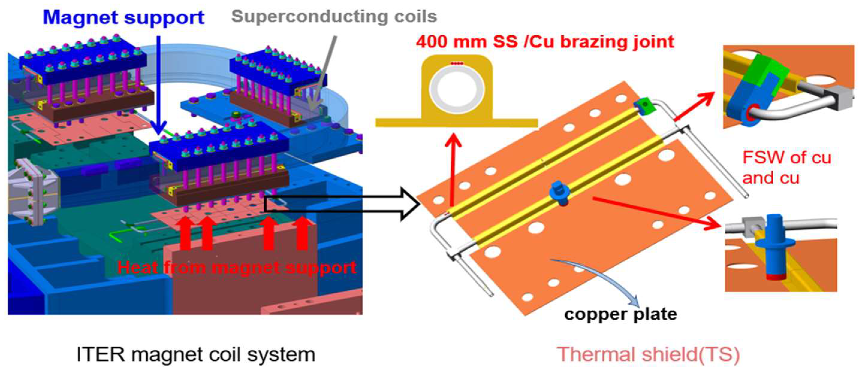
As a critical component of the superconducting magnet system, the 18 correction coils (CC) are used to compensate for field errors arising from the misalignment of the coils and winding deviations from the nominal shape as a result of fabrication tolerances, joints, leads, busbars and assembly tolerances [3]. In order to maintain the suitable operation of the ITER machine, the temperature of the CC superconducting coils shall be kept lower than the current sharing temperatures of 6–8 K to stay superconductive. Unfortunately, there was thermal disturbance, electromagnetic heat and eddy current heat generated by AC loss, etc. In addition, each magnet support that contacts the superconducting coils as a source of heat is approximately 16 kW during the normal and abnormal operation of the ITER tokamak, as shown in Figure 2, in order to intercept the heat from the magnet support to the superconducting coils. The thermal shield (TS), composed of brazed copper and 316L tubes, was located between the magnet support and the superconducting coils. Helium with a temperature of 12 K and pressure of 0.5 MPa was injected into the 316L SS tubes of TS, cutting off the heat from the magnet supports.
The fabrication design of the TS is presented in Figure 2. Three steps of joint processes were employed in this fabrication design as per the quality requirements of ITER. First and foremost, the SS/Cu pipes were bonded by vacuum brazing. After that, the FSW of copper plates was adopted for the joining of copper plate and the as-brazed SS/Cu assembly. Lastly, the TIG SS tubes were connected via TIG welding. The details of the joining process were developed as follows:
- (a)
- Surface preparation:
For a better wettability of AgCu28wt% with SS, nickel plating with a thickness of 3–10 μm was carried out on the surface of the SS tube. After that, the plated SS was ultrasonically cleaned with anhydrous ethanol and dried with compressed inert gas.
- (b)
- High-precision drilling of the copper block:
The high-precision drilling was adopted for the deep hole with a length of up to 400 mm. After that, the wings were fabricated at each side of the copper block and butt welded with the 3 mm copper plate later via FSW welding. After that, the Ni-plated SS tubes were inserted into the copper block with a strictly controlled brazing clearance of 0–0.02 mm. Lastly, the filler materials AgCu28wt% with a diameter of 1 mm were inserted into the as-drilled tiny hole for uniform packing in the longitude direction of the SS tube.
- (c)
- Three kinds of jointing activities:
Step 1, the SS/Cu assemblies were put in a vacuum-brazing furnace. Step 2, as illustrated in Figure 2, the following welding parameters of FSW were used: the welding speed of 100 mm/min, the rotational speed of 500 rpm and the welding pressure of 1000 N. Step 3, the automatic tungsten inert gas protection (TIG) welding was employed to join the 316L tubes (Figure 2). The selected TIG welding parameters were 95–105 A and 12–15°/s for current and welding speed, respectively.
The brazing quality of the as-brazed 316 L tube and Cu block joint plays a critical role in the thermal conductivity performance of the TS. Unfortunately, the joining of copper to stainless steel is challenging because of the differences in melting point, thermal expansion coefficient, wettability and thermal conductivity between stainless steel and copper [4,5]. Many studies on the connection of copper and stainless steel have been carried out to obtain defect-free joints by laser welding, tungsten/metal gas-suspended arc welding, diffusion bonding and vacuum brazing [6,7,8,9,10,11,12,13,14,15,16,17,18,19,20,21]. Li Xiangbin et al. performed vacuum brazing on 100 mm SS and CuCrZr pipe with foil-shaped BAg-6 filler at 690 °C and a pressure of 8 × 10⁻³ Pa, and the shear strength of the as-brazed joint was higher than 90 MPa [15]. Cheng Jiming et al. have assessed the feasibility of the explosive welding process of the SS plate to the CuCrZr plate. The maximal shear strength of the SS/CuCrZr joint was higher than 240 MPa [11]. A hot isostatic pressing was carried out by S.H. Goods et al. to join the SS tube to the CuCrZr base in the ITER first wall at 1040 °C and 103 MPa for 2 h. The tensile strength of the joints was higher than 230 MPa [16]. In particular, Abhay Kumar et al. [13] studied the brazing process, mechanical properties and microstructure of the SS and copper joints of nickel-plated stainless steel. The results revealed that a joint with a shear strength of 170 MPa could be obtained in an overlap joint style with a short distance of 17 mm. Nevertheless, copper/stainless steel components in the ITER TS are cylinder-shaped, with a length of up to 400 mm, and compared with shorter length overlap joints such as 17 or 100 mm, the machining accuracy of a deeper copper block inner hole and the straightness of longer steel pipe turned out to have worse results. Therefore, it is hard to control the brazing clearance of the SS/Cu assemblies strictly and uniformly along the whole 400 mm length, which increases the difficulty of long-distance SS/Cu brazing joints significantly.
In summary, satisfactory brazing joints of copper-stainless steel can be obtained by using a silver-based filler metal and by the adoption of vacuum brazing. Unfortunately, previous studies have predominantly ignored the brazing process and have opted for long-brazing joints with overlap lengths of more than 100 mm. This work aims to find a feasible way of achieving long-distance vacuum brazing joints with a high-brazing ratio and thermal conductivities. The findings of this paper can improve and ensure the cooling efficiency and reliability of the cooling components adopted in the fusion device. Furthermore, it has the advantages of a high-braze ratio and production efficiency due to the adoption of three different joining methods. It can thus be especially suitable for fabricating the extremely heat-loaded components in the fusion reactor and extended to the brazing activities of copper, stainless steel and nickel alloy in aerospace, nuclear power and other applications.
2. Experimental Procedure
In this study, 316L austenitic stainless steel tubes and T2 copper blocks were used as base metals. The 316L tubes had a length of 1000 mm, an outer diameter of 17.10 mm and a thickness of 2.25 mm. The measured chemical composition of the 316L alloy was 0.64 Si, 14 Ni, 1.8 Mn, 2.92 Mo, 0.024 C, 0.001 S, 0.02 P (all in wt.%) and the balance was Fe. The as-received oxygen-free electronic copper with a thickness of 25 and 3 mm had measured chemical compositions of 99.96 Cu, 0.02 Ag, 0.02 S, 0.01 P, 0.02 Bi, 0.05 Fe and 0.01 Pb (all in wt.%). Silver-copper eutectic-filler alloy (72 Ag/28 Cu, wt.%) in the form of a wire with a diameter of 1 mm was used as the filler material.
The fabrication joining process was conducted as follows for the achievement of a perfect brazing clearance (0–0.04 mm) before brazing: firstly, the SS pipes were selected by a gauge with two deep holes which were similar to a go/no-go gauge for better precision of the outer diameter and straightness. Secondly, the surface of the plated SS was ultrasonically cleaned with alcohol and blown dry with dry N2 gas. After that, the surface of the 316L stainless steel tube was coated with a Ni layer of about 3–10 μm in thickness by using the ML-80 semi-gloss for the electroless nickel plating process. Subsequently, a high-precision depth drill was adopted for the inner hole with a diameter from 17.11 to 17.15 mm and a length of 400 mm. Lastly, the SS pipes were injected into the block manually, making a very tight brazing clearance between the SS pipes and the copper block.
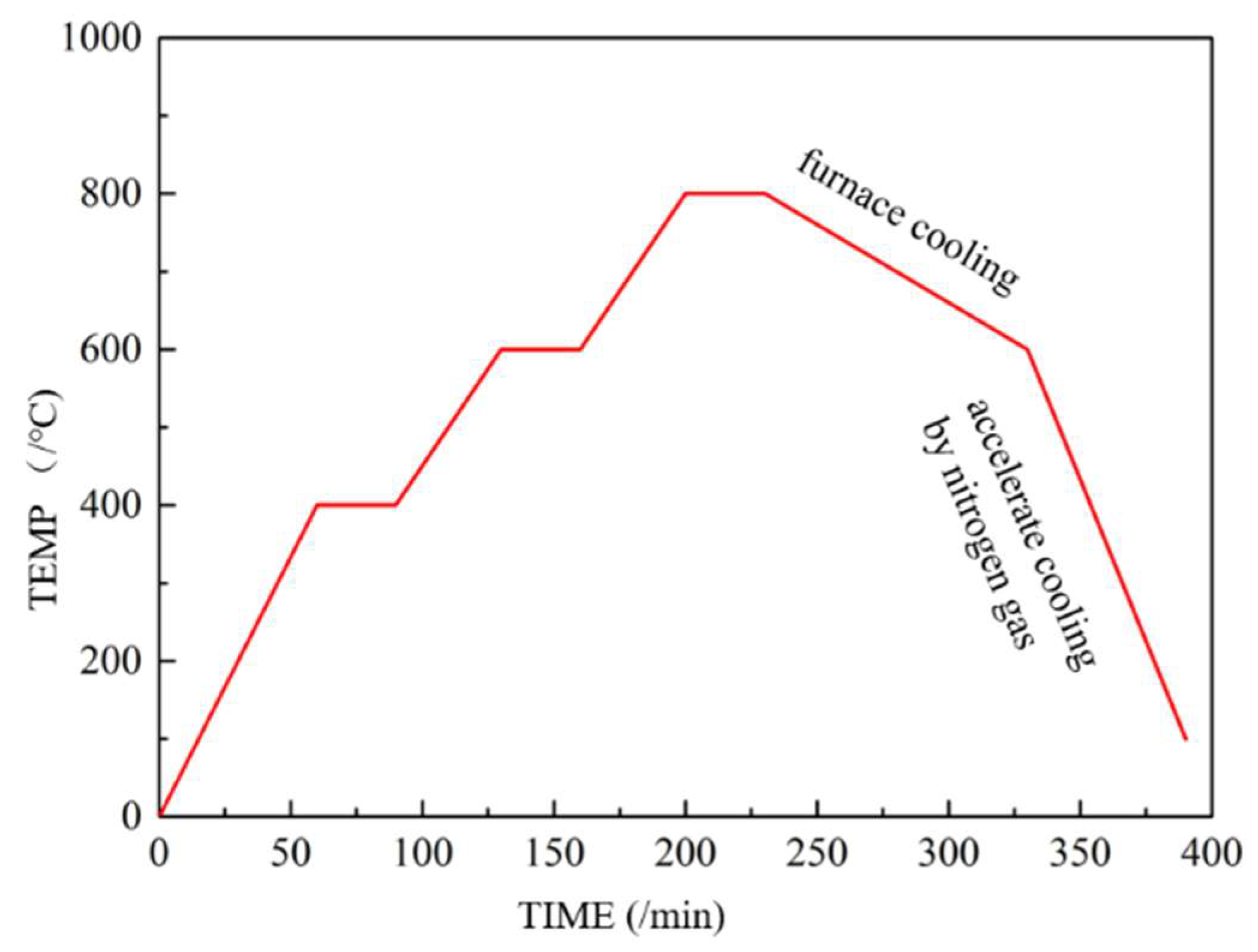
Figure 2 characterized the preparation of long-length SS/Cu and 316 L tube joints. The brazing clearance of the SS/Cu joint was strictly controlled at 0–0.04 mm. Subsequently, the brazing was carried out at 8 × 10⁻³ Pa and 800 °C for 30 min. After that, the as-brazed assemblies were cooled to 580 °C in a furnace. Finally, in order to avoid the deterioration of as-brazed joints, as-brazed joints were rapidly chilled at the rate of 10–20 °C/min to 200 °C by introducing and circulating cooling argon gas. The details of the vacuum-brazing process were shown in Figure 3.
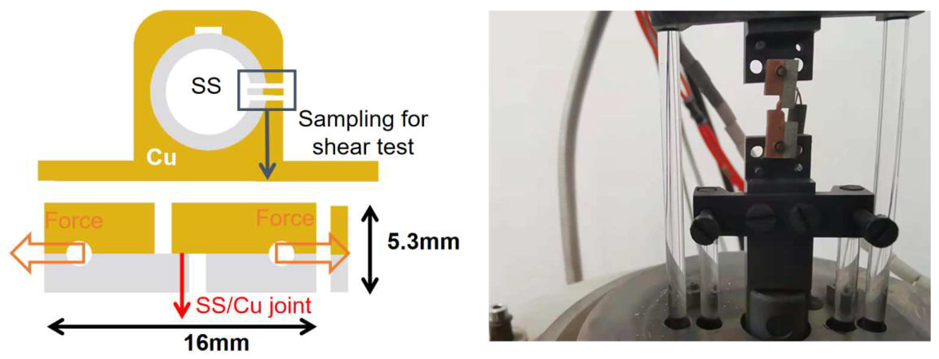
The microstructures of the brazed joints were observed via an optical microscope (ZEISS AXIO) and scanning electron microscopy (ZEISS EVO18 Special Edition) equipped with an energy-dispersive spectrometer (EDS). The samples were ground progressively with 200#, 400#, 800# and 1000# SiC sandpaper, and then polished with a diamond paste. A mixture of FeCl3:HCl:H2O = 5:20:100 was employed for etching the as-brazed joints before the optical microscope test (OM). A Vickers microhardness test was conducted via an HXD-1000TM hardness tester with a test load of 100 N and a holding time of 10 s for each point. The shear strength of the joints was sampled as shown in Figure 4. After that, the shear strength of the two as-brazed samples was examined by a bespoke micro-tensile test machine with a maximum tensile force of 1000 N at 0.2 mm/s cross-head speed. Subsequently, in order to have a better understanding of the fracture behavior during the shear strength test, the characteristics of the shear fracture surfaces were analyzed with the naked eye and SEM.
3. Results and Discussion
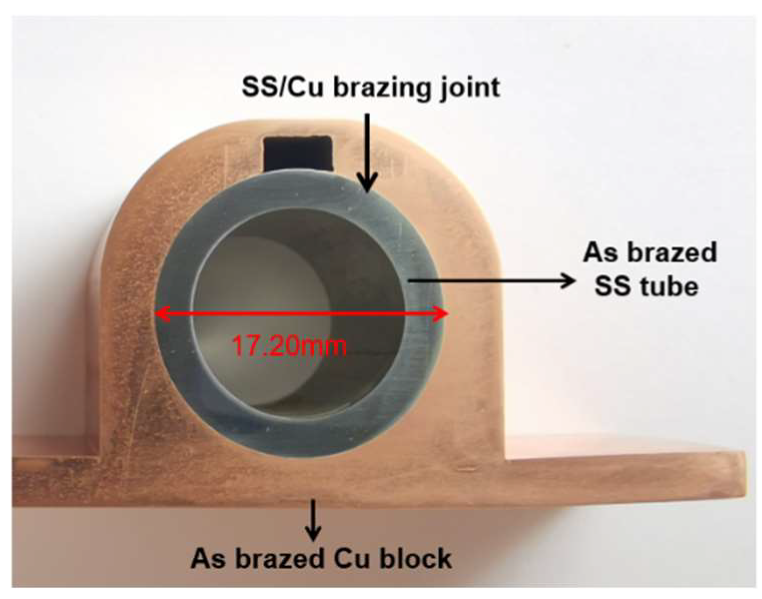
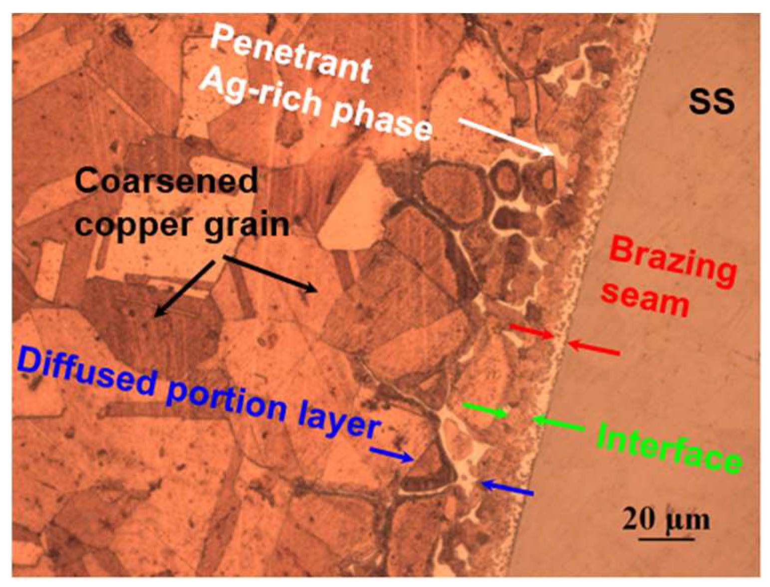
The macromorphology of the brazed joint is presented in Figure 5. It suggests that the as-brazed SS/Cu interface is smooth, without any porosity, cracks or dis-bonded areas. Figure 6 evaluates a high-resolution image of the Cu/SS steel-brazed joint by OM. The OM observation on the cross-section of the SS/Cu brazed joint reveals that the thickness of the interface is about 130–150 μm. Of note, the brazing joint is composed of a brazing seam center area with a thickness of approximately 10 μm, an interface area of the brazing seam layer with a thickness of about 20 μm and a diffused portion layer with a thickness of 100 μm. For the diffused portion layer, the primary crystal of Cu grows close to the Ni layer, due to the good wettability of Cu on the Ni layer. During the brazing activities, the molten filler materials infiltrated into the grain boundaries of the coarsened copper grains with a distance of 40–100 μm. This phenomenon is consistent with what was reported in the literature [13]. During the cooling process after brazing, the copper grew along the Ni layer that was formed by the nickel plating and the molten filler automatically flowing to the Cu grain boundary, resulting in the Ag-rich phase mainly distributed near the copper side after brazing.
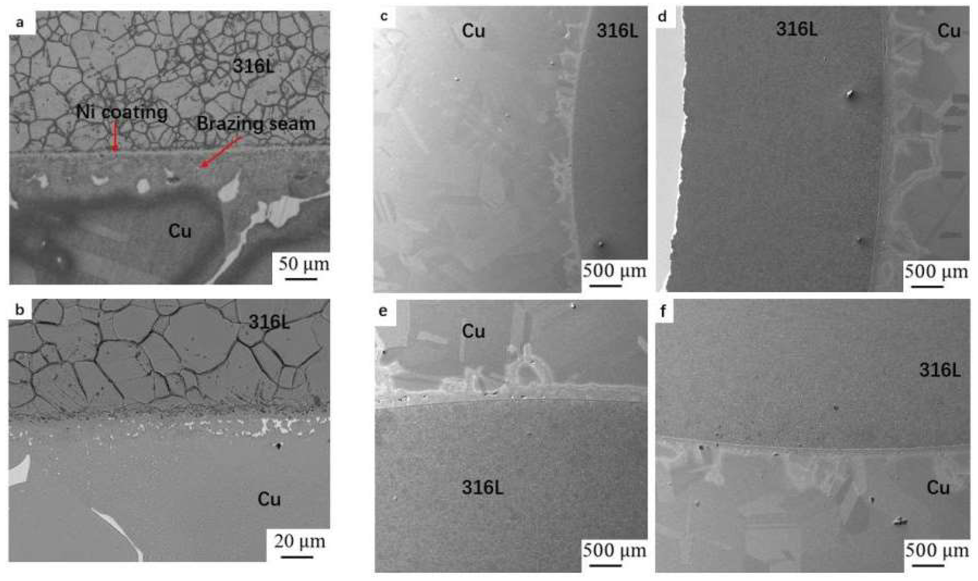
Optical micrographs and back scattered images of the brazed joint are characterized in Figure 7a,b, respectively. The microstructure of the 316L side is equiaxial austenite and the copper side is a Cu phase with a small amount of silver penetrating into the copper grain boundaries. Figure 7c–f presents SEM images of the entire joint interface. The microstructure of the SS side of the brazed joint is equiaxial austenite. However, the microstructure of the copper side of the brazed joint is a Ag-rich phase (Ag-Cu) penetrating into the coarsened copper grain boundaries. The results indicate that a good metallurgical combination was achieved between the copper block and the SS tube. Additionally, a braze ratio of 100% is revealed in Figure 7a–f as no defects such as pores, voids or cracks can be observed. This demonstrates that the high-precision deep-hole drilling technology adopted in this paper ensured the best control of the brazing clearance, resulting a good wettability and fluidity of the SS pipes and the copper during brazing.
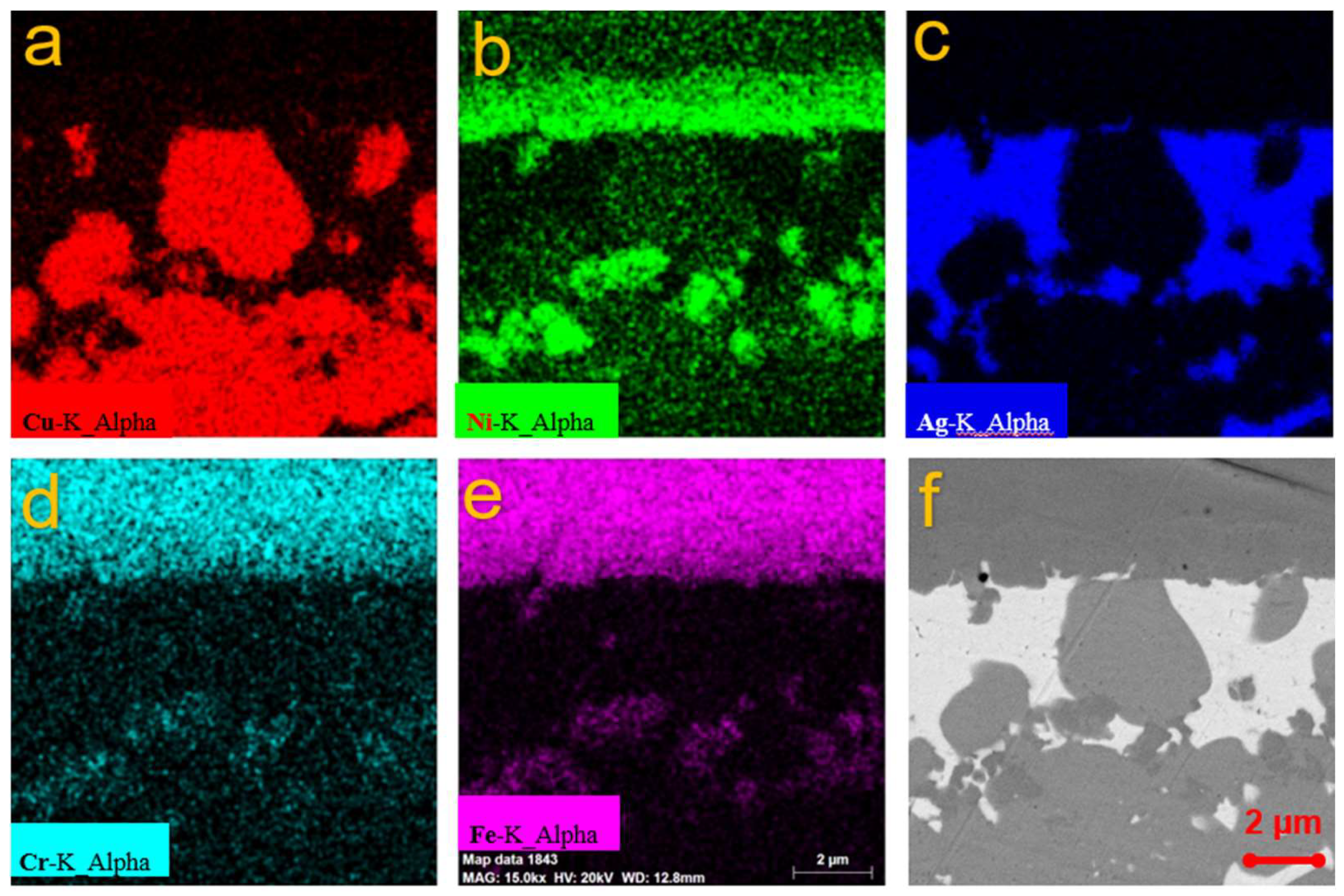
To further assess the detail of the joints, Figure 8 presents the EDS maps of the brazed joint. It was determined by the EDS that the brazing seam was composed of a Cu and Ag-rich phase. Furthermore, Ni atoms were present at the brazing seam, which means that the Ni layer was partially melted into the braze seam during the brazing thermal cycle. It is worth noting that the brazing temperature was 830 °C, which is lower than the melting point of Ni (1453 °C). This suggests that the molten liquid was a mixture of Ni, Cu and Ag. Additionally, it was revealed in Figure 7 that Fe and Cr atoms also diffused into the Cu base metal over a long distance during brazing. It is interesting to note that Fe and Cr atoms barely existed in the brazing seam. This was mainly due to the low solubility of Fe and Cr in Cu. On the other hand, there is no doubt that the solubility of the Fe and Cr in Ni was very high. Hence, it can be hypothesized that the Fe and Cr mainly dissolve into Ni, leading to the long-range diffusion of the Fe and Cr along with the Ni-Cu-Ag melt. The above results prove that the interdiffusion of Cu, Ni, Fe and Ag elements between substrates and filler metal is sufficient for good metallurgical bonding in the brazed joint.
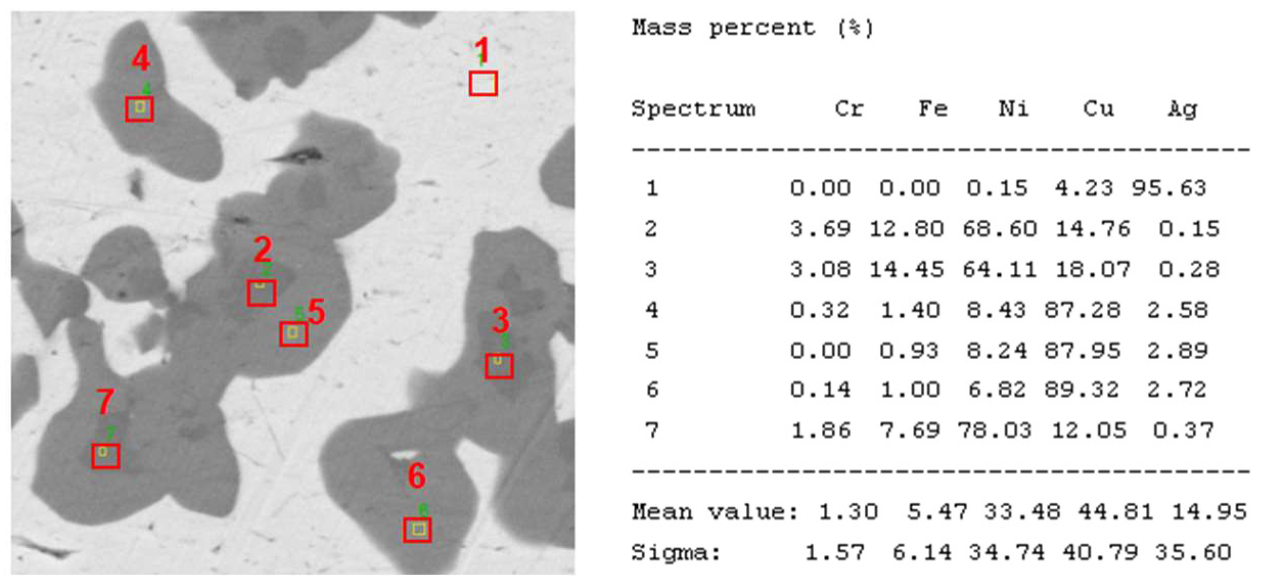
The EDS analysis of seven points of the brazing seam with different colors is shown in Figure 9. Point 1 is the Ag-Cu solid solution, in which the Cu content (4.23 wt.%) is lower than the composition (8.8 wt.%) of eutectic Ag-Cu (that is, the molten filler material). This implies that the Cu in the eutectic Ag-Cu may have diffused into the base material or other areas during cooling. In addition, the Cr and Fe dissolving into the Ni layer is proved by the composition of the dark area (points 2, 3 and 7). Furthermore, the solid solution formed by the Ni and Cu is also detected in the gray areas of point 5, point 6 and point 4. Of note, points 4, 5 and 6 have a lower content of Fe and Cr than point 7, point 3 and point 2, which suggests that the time for solidification in the gray area is later than that in the dark area, since the melt points of the Fe and Cr are much higher than that of the Cu and Ag.
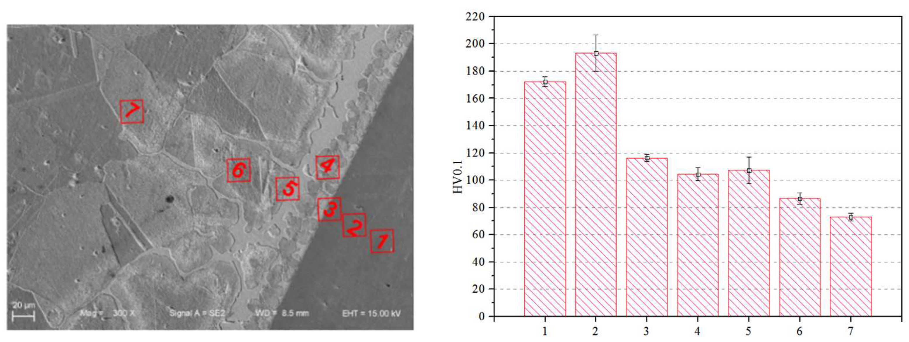
Generally speaking, as shown in Figure 10, it can be speculated that the hardness of the as-brazed SS/Cu joints reveals a downtrend from the SS to the copper side. The softest area is the base material on the copper side; 7# with a value of 76 HV. In contrast, the SS base material, point 2#, presents a peak hardness value of 193 HV. Point 1# shows a hardness value of 173 HV, which is slightly lower than point 2#. Turning to point 3#, the interface of the SS side, the hardness value indicated a sharp decrease to 116HV. Then at point 4#, the hardness value of the interface area of the brazing seam layer leveled off at around 104 HV. Apart from the above, the hardness of the interface area on the copper side (5#), the copper-base metal Ag-rich eutectic penetrating area (6#) and copper base metal area without Ag-rich eutectic penetration (7#) are 107 HV,86 HV and 76 HV, respectively.
In general, the change in the trend of the microhardness curve in the cross-section of the joint is consistent with the microstructure, grain size and the degree of completely dynamic recrystallization [20]. It is clear that the difference in the base material of the SS compared with copper results in the hardness of points 1# to 3# being higher than that of points 4# to 6#. Due to the influence of the brazing thermal cycle, the grains of the copper-base material are seriously coarsened, which is the main reason for the reduction of hardness on the copper-base metal side.
However, it can be concluded that the penetration of Ag-rich eutectic in the grain boundary significantly improves the hardness of copper when comparing the hardness of points 5#, 6# and 7#. It is important to point out that the interface area of the brazing seam layer (4#) indicates a lower hardness than the interface of the SS (3#) and copper side (5#), proving that it is the weakest area of the as-brazed Cu-SS joints.
It is worth pointing out that because the thickness of the brazed seam is just 10–20 μm, the microhardness test cannot be carried out precisely on this area, which makes it impossible to estimate the hardness of the brazing seam. However, there is no doubt that the narrower the thickness of the brazing seam, the higher the tensile strength of the brazed joint, which proves that the brazing procedure is quite suitable for the long-overlap length SS/Cu pipe joint.
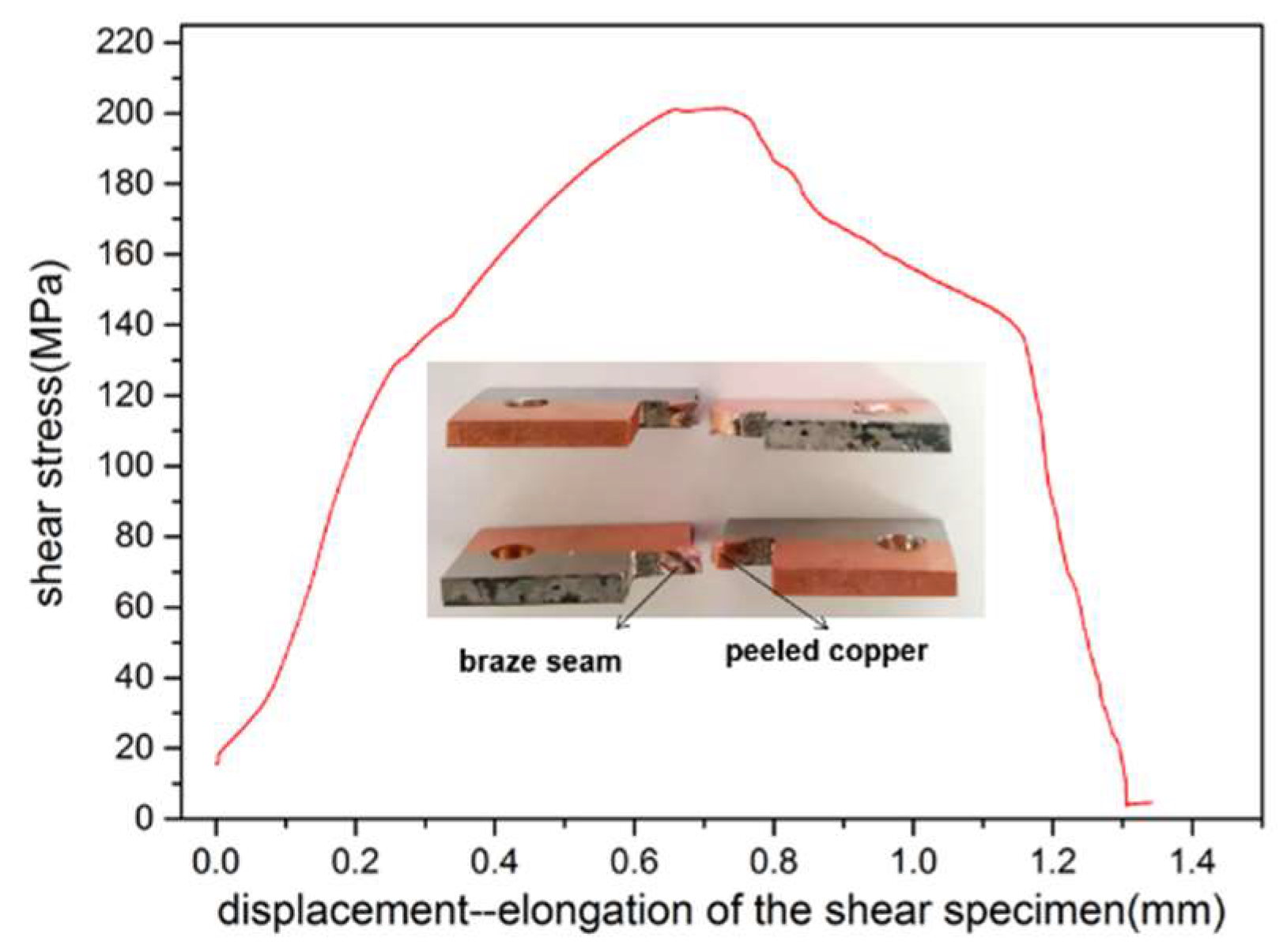
The shear strength test specimens, shear stress-displacement curve and SEM analysis of the fracture of the samples are illustrated in Figure 11 and Figure 12, respectively. As shown in Figure 11, the shear test of two samples revealed that the shear strength of the brazed joints is 202 MPa and 208 MPa, respectively. It can be found that the shear fracture presents a white color to the naked eye. It seems that the whole copper near the braze weld is torn off. At a closer look, the crack propagated along the copper side of the whole brazed joint. This demonstrates that the overall process conforms to the test results of the hardness test as shown in Figure 10. From the perspective of the microhardness distribution across the interface of the as-brazed SS/Cu joint, the coarse grain of the copper indicated the lowest hardness value. Therefore, this zone is the most vulnerable zone of all of the joints and is the crack initiation point and the weakest area of the whole joint.
From the perspective of fracture position, since the fracture position is located at the base material (copper side), it demonstrates the good metallurgical bonding of the SS and copper. To have a better configuration of the shear strength, a fracture morphology by SEM was carried out and the results were shown in Figure 12.
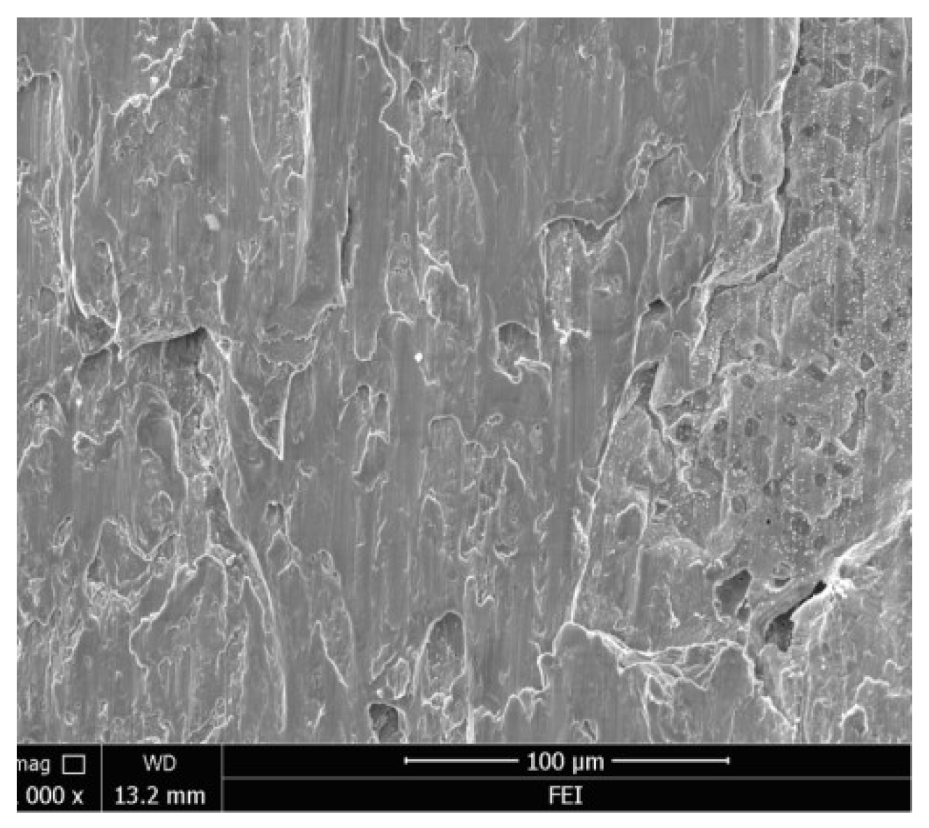
For the specimens bearing shear stress, the tearing is mainly due to the shear loading. The shear stress of the joints increases cumulatively up until the crack is initiated, and the crack mouth becomes progressively larger with the increase of the shear load. In addition, the fracture morphology is typical shear fracture morphology, which indicates that the as-brazed SS/Cu joints are ductile in nature. Obviously, the shear strength, fracture location of the brazing joints and metallurgical reaction indicate that the brazed joint is very desirable. In addition, the fracture position of the as-brazed SS/cu joints is consistent with the hardness test result, as shown in Figure 10.
4. Conclusions
This paper presents a feasible fabrication design for the CCS TS, which is accomplished by three kinds of jointing processes. A key point was to achieve the remarkable thermal conductivity performance of the ITER thermal shield. Successfully fabricated and studied were the high shear strength, superior brazing rate and excellent reliability of the 400 mm length of the SS/Cu joint. The following test results reveal the outstanding performances of the as-brazed SS/Cu joints:
- The high, precise-depth drill of copper block employed in this paper ensured a favorable control of the brazing clearance for the SS/Cu joint, contributing to a 100% braze ratio for the long-length SS/Cu joints.
- The hardness of the as-brazed SS/Cu joints reveals a downtrend from the SS to the copper side, and the copper-base material represents the lowest hardness value by the coarse grain induced by the brazing thermal cycle. Ag-rich eutectic to the copper grain boundary improves the hardness of copper significantly.
- The brazed seam consisted of the Ag-rich phase and the Cu-rich phase; the Ag-rich phase penetrates into the grain boundaries of copper during vacuum brazing.
- The shear test reveals that the average shear strength of the SS/Cu joint is 205 MPa and the fracture morphology is typical shear fracture morphology which indicates good plastic toughness. The crack is generated, propagated and fractured at the copper side with coarse grain, which is consistent with the result of the hardness test.
Author Contributions
Conceptualization, Y.W. (Yu Wang); methodology, Y.W. (Yu Wang); validation, Q.S.; investigation, Y.W. (Yu Wang) and Q.S.; data curation, Y.W. (Yu Wang), J.Z., X.W. and Y.W. (Yafeng Wang); writing—original draft preparation, Y.W. (Yu Wang), X.W. and Y.W. (Yafeng Wang); writing—review and editing, Q.S. and J.Z.; visualization, Y.W. (Yu Wang); supervision, A.H.; project administration, A.H.; funding acquisition, Q.S. All authors have read and agreed to the published version of the manuscript.
Funding
ITER-National Magnetic confinement Fusion Program of China (No. 2008GB107000) and Young People Fund of Jiang Xi Province (No. 2018BAB216005).
Data Availability Statement
Data available on request from the authors.
Conflicts of Interest
The authors declare that they have no known competing financial interests or personal relationships that could have appeared to influence the work reported in this paper.
References
- Huguet, M. The ITER magnet system. Fusion Eng. Des. 1997, 36, 23–32. [Google Scholar] [CrossRef]
- Mitchell, N.; Bessette, D.; Gallix, R.; Jong, C.; Knaster, J.; Libeyre, P.; Sborchia, C.; Simon, F. The ITER magnet system. IEEE Trans. Appl. Supercond. 2008, 18, 435–440. [Google Scholar] [CrossRef]
- Bauer, P.; Ballarino, A.; Devred, A.; Ding, K.; Dong, Y.; Niu, E.; Du, Q.; Gung, C.Y.; Han, Q.; Heller, R. Development of HTS Current Leads for the ITER Project. IOP Conf. Ser. Mater. Sci. Eng. 2020, 756, 012032. [Google Scholar] [CrossRef]
- Wei, J.; Du, S.S.; Foussat, A.; Yu, X.; Liu, L.; Han, S.; Liu, X.; Wu, W.; Dolgetta, N.; Libeyre, P. R&D of the ITER correction coil magnet system in China. In Proceedings of the 23rd IAEA (International Atomic Energy Agency) Fusion Energy Conference, Daejeon, Republic of Korea, 11–16 October 2010. [Google Scholar]
- Zhang, Y.; Huang, J.; Chi, H.; Cheng, N.; Cheng, Z.; Chen, S. Study on welding–brazing of copper and stainless steel using tungsten/metal gas suspended arc welding. Mater. Lett. 2015, 156, 7–9. [Google Scholar] [CrossRef]
- Sánchez, L.; Carrillo, D.; Rodríguez, E.; Aragón, F.; Sotelo, J.; Toral, F. Development of high precision joints in particle accelerator components performed by vacuum brazing. J. Mater. Process. Technol. 2011, 211, 1379–1385. [Google Scholar] [CrossRef]
- Yuan, X.; Tang, K.; Deng, Y.; Luo, J.; Sheng, G. Impulse pressuring diffusion bonding of a copper alloy to a stainless steel with/without a pure nickel interlayer. Mater. Des. 2013, 52, 359–366. [Google Scholar] [CrossRef]
- Guo, S.; Zhou, Q.; Kong, J.; Peng, Y.; Xiang, Y.; Luo, T.; Wang, K.; Zhu, J. Effect of beam offset on the characteristics of copper/304stainless steel electron beam welding. Vacuum 2016, 128, 205–212. [Google Scholar] [CrossRef]
- Qiyun, Z.; Hongshou, Z. Brazing Manual; China Machine Press: Beijing, China, 2008. [Google Scholar]
- Davis, J.W.; Smith, P.D. ITER Material Properties Handbook. J. Nucl. Mater. 1996, 233–237, 1593–1596. [Google Scholar] [CrossRef]
- Wang, K.; Chen, J.; Wang, P.; Liu, X.; Bao, L.; Raffray, R.; Barabash, V.; Wang, Z.; Niu, E.; Fang, T.; et al. China’s technological achievements on ITER enhanced heat flux first wall in the pre-PA qualification. Fusion Eng. Des. 2019, 146, 2045–2048. [Google Scholar] [CrossRef]
- Sabetghadam, H.; Hanzaki, A.Z.; Araee, A. Diffusion bonding of 410 stainless steel to copper using a nickel interlayer. Mater. Charact. 2010, 61, 626–634. [Google Scholar] [CrossRef]
- Kumar, A.; Ganesh, P.; Kaul, R.; Yadav, D.P.; Karnewar, A.K.; Yedle, K.N.; Gupta, R.K.; Singh, M.K.; Ram Sankar, P.; Bhatnagar, V.K.; et al. Study on requirement of nickel electroplating in OFE copper-316L stainless steel brazed joints. Int. J. Adv. Manuf. Technol. 2016, 87, 2639–2651. [Google Scholar] [CrossRef]
- Yao, C.; Xu, B.; Zhang, X.; Huang, J.; Fu, J.; Wu, Y. Interface microstructure and mechanical properties of laser welding copper–steel dissimilar joint. Opt. Lasers Eng. 2009, 47, 807–814. [Google Scholar] [CrossRef]
- Li, X.; Shi, Y. Preliminary Process Design of ITER ELM Coil Bracket Brazing. Plasma Sci. Technol. 2015, 17, 259. [Google Scholar] [CrossRef]
- Goods, S.H.; Puskar, J.D.; Watson, R.M. Development of joining processes and fabrication of US first wall qualification mockups for ITER. In Proceedings of the 2009 23rd IEEE/NPSS Symposium on Fusion Engineering, San Diego, CA, USA, 1–5 June 2009. [Google Scholar]
- Magnabosco, I.; Ferro, P.; Bonollo, F.; Arnberg, L. An investigation of fusion zone microstructures in electron beam welding of copper–stainless steel. Mater. Sci. Eng. A 2006, 424, 163–173. [Google Scholar] [CrossRef]
- Phanikumar, G.; Manjini, S.; Dutta, P.; Chattopadhyay, K.; Mazumder, J. Characterization of a continuous CO2, laser-welded Fe-Cu dissimilar couple. Metall. Mater. Trans. A 2005, 36, 2137–2147. [Google Scholar] [CrossRef] [Green Version]
- Jayabharath, K.; Ashfaq, M.; Venugopal, P.; Achar, D.R.G. Investigations on the continuous drive friction welding of sintered powder metallurgical (P/M) steel and wrought copper parts. Mater. Sci. Eng. A 2007, 454–455, 114–123. [Google Scholar] [CrossRef]
- Tsuchiya, K.; Kawamura, H. Mechanical properties of Cu, Cr, Zr alloy and SS316 joints fabricated by friction welding method. J. Nucl. Mater. 1996, 233–237, 913–917. [Google Scholar] [CrossRef]
- Ji, H.; Deng, Y.; Xu, H.; Lin, S.; Wang, W.; Dong, H. The mechanism of rotational and non-rotational shoulder affecting the microstructure and mechanical properties of Al-Mg-Si alloy friction stir welded joint. Mater. Des. 2020, 192, 108729. [Google Scholar] [CrossRef]
Figure 1.
The ITER machine.

Figure 2.
The position and design of the ITER CCS thermal shield.

Figure 3.
Thermal cycle of the SS/Cu vacuum brazing.

Figure 4.
Schematic diagram of the specimens sampling and the shear strength test.

Figure 5.
The as-brazed Cu/SS joint.

Figure 6.
The interface of the as-brazed Cu/SS joint.

Figure 7.
Microstructure of the brazed joint: (a) optical micrograph; (b) backscattered image; (c–f) SEM images of the entire joint interface in detail.
Figure 7.
Microstructure of the brazed joint: (a) optical micrograph; (b) backscattered image; (c–f) SEM images of the entire joint interface in detail.

Figure 8.
EDS maps of the as brazed Cu/SS joint. (a) the Cu; (b) the Ni; (c) the Ag; (d) the Cr; (e) the Fe; (f) the interface of the joint.
Figure 8.
EDS maps of the as brazed Cu/SS joint. (a) the Cu; (b) the Ni; (c) the Ag; (d) the Cr; (e) the Fe; (f) the interface of the joint.

Figure 9.
EDS points analysis of interface of the as brazed joint.

Figure 10.
Microhardness distribution across the interface of the as-brazed SS/Cu joint.

Figure 11.
Shear behavior of as brazed SS/Cu specimens.

Figure 12.
SEM of the fractured surface.

Disclaimer/Publisher’s Note: The statements, opinions and data contained in all publications are solely those of the individual author(s) and contributor(s) and not of MDPI and/or the editor(s). MDPI and/or the editor(s) disclaim responsibility for any injury to people or property resulting from any ideas, methods, instructions or products referred to in the content. |
© 2023 by the authors. Licensee MDPI, Basel, Switzerland. This article is an open access article distributed under the terms and conditions of the Creative Commons Attribution (CC BY) license (https://creativecommons.org/licenses/by/4.0/).
Share and Cite
MDPI and ACS Style
Wang, Y.; Shang, Q.; Zeng, J.; Hou, A.; Wang, X.; Wang, Y. Vacuum Brazing and Performance Evaluation of T2 Copper Block and 316L Stainless Steel Tube. Metals 2023, 13, 1349. https://doi.org/10.3390/met13081349
AMA Style
Wang Y, Shang Q, Zeng J, Hou A, Wang X, Wang Y. Vacuum Brazing and Performance Evaluation of T2 Copper Block and 316L Stainless Steel Tube. Metals. 2023; 13(8):1349. https://doi.org/10.3390/met13081349
Chicago/Turabian StyleWang, Yu, Qiao Shang, Jing Zeng, Ailin Hou, Xiaoxia Wang, and Yafeng Wang. 2023. "Vacuum Brazing and Performance Evaluation of T2 Copper Block and 316L Stainless Steel Tube" Metals 13, no. 8: 1349. https://doi.org/10.3390/met13081349
Note that from the first issue of 2016, this journal uses article numbers instead of page numbers. See further details here.