Article

Microstructure and Tribological Behavior of Cr-Mn-N Steel with Age-Hardened Near-Surface Layer including CrN and Fe2N Particles Intended for Use in Orthopedic Implants

1
Laboratory of Physical Mesomechanics of Materials and Non-Destructive Testing, Institute of Strength Physics and Materials Science of Siberian Branch of Russian Academy of Sciences, 634055 Tomsk, Russia
2
Laboratory of Physics of Nanostructured Biocomposites, Institute of Strength Physics and Materials Science of Siberian Branch of Russian Academy of Sciences, 634055 Tomsk, Russia
*
Author to whom correspondence should be addressed.
Metals 2023, 13(8), 1328; https://doi.org/10.3390/met13081328
Submission received: 20 June 2023 / Revised: 19 July 2023 / Accepted: 20 July 2023 / Published: 25 July 2023

Abstract

:
This paper presents the results of a study of 17%Cr-19%Mn-0.53%N high-nitrogen austenitic stainless steel with a 25 µm thick dispersion-hardened near-surface layer intended for orthopedic applications. It was modified using a mechanical–thermal treatment (MTT) that included both friction processing and subsequent electron beam processing. The friction processing enabled the formation of a microstructure with a high dislocation density and strain twins, and it also initiated strain aging in the near-surface layer. At this stage, the hardening was achieved via the formation of CrN particles coherent to the matrix with the face-centered cubic (FCC) lattice and via the relaxation of internal stresses. After electron beam processing, the volume fraction of the nanodispersed phases increased. In the near-surface layer, a highly dispersed microstructure with a grain size of 3 μm, reinforced with CrN and Fe2N nanoparticles, was observed using transmission electron microscopy. The MTT increased the microhardness of the surface layer, and this contributed to the enhancement in both the H/E and H3/E2 ratios. This indicated an improvement in the crack resistance of the steel under frictional loads. The MTT also enhanced both the yield point (up to 580 MPa) and the wear resistance (by 50% to 100%, depending on the applied load) compared with those of the same steel after it had undergone quenching. In addition, the wear resistance was many times greater than that of the Ti-6Al-4V alloy typically used for manufacturing orthopedic implants. After the MTT, the properties of the near-surface layer of the steel indicated its suitability for biomedical applications.

1. Introduction

Endoprosthesis is essential in the treatment of severe joint damage caused by osteoarthritis or trauma [1]. Metal alloys and ceramics are used in the manufacture of endoprostheses, and these operate in friction pairs with an insertion carried out via ultra-high molecular weight polyethylene (UHMWPE), metal, or ceramic material [1,2,3]. The service life of a prosthesis is limited; it depends upon the wear resistance of the materials used since debris from the prosthesis can affect the bone tissue and thereby damage and weaken the prosthesis fixation. Both metal and UHMWPE surfaces wear out in such cases. Ceramic–ceramic friction pairs are the most durable. In this case, the friction coefficient is minimal and no wear is typically observed. However, they are the most expensive prosthesis and are difficult to manufacture. To increase the availability of implants with an indefinite service life, it is necessary to utilize new and advanced materials that, along with their biocompatibility, bioinertness, and great strength properties, are characterized by great tribological characteristics (namely, low friction coefficients and wear rates).
In recent years, nickel-free, corrosion-resistant austenitic steels alloyed with nitrogen have been actively studied for their potential use in biomedical applications [4,5,6,7,8,9,10]. The reported data indicate that this class of steel meets all the requirements for use in endoprosthesis parts. Compared with 319L steel and the Co-28Cr-6Mo [6,7,8,9,10,11] and Ti-6Al-4V alloys [12], they possess greater wear resistance, mechanical properties, corrosion resistance, biocompatibility, and bioinertness.
Titanium and its alloys are widely used in orthopedics due to their superior combinations of both strength and biocompatibility. In addition, the Ti-6Al-4V alloy possesses a lower Young’s modulus (110 GPa) [13] than both stainless steels and cobalt-based alloys. However, it has insufficient wear resistance [12]. In order to increase the hardness of the surface layer of the Ti-6Al-4V alloy and improve its wear resistance, deformation processing methods can be applied [14,15]; these methods combine deformation processing with surface alloying [16] and the deposition of coatings [17,18]. Not all of the above surface hardening methods are applicable to the manufacturing of orthopedic implants since the surface layers should be characterized by both high adhesion and sufficient thicknesses, and thereby reduce roughness upon finishing.
The wear resistance of high-nitrogen steels is achieved via chemical hardening procedures such as low-temperature plasma nitriding [18]. For example, the wear resistance of Fe-17Cr-20Mn-0.5N steel has been increased via the formation of a two-phase γ/ε microstructure obtained using a shear mechanism without the presence of any dispersed phases [19,20].
Microstructure refinement is a promising way to improve the above characteristics. Dispersion to the nanoscale is carried out via plastic deformation. However, hardening is accompanied by a decrease in ductility in the maximum deformed state. Therefore, two or more surface modification procedures can be implemented in a single production route, allowing the formation of a fine-grained structure without any deformation defects. Previously, severe plastic deformation of 319L grade steel combined with intermediate annealing [11], or mechanical–thermal treatment of the near-surface layer of Cr-Mn-N steel [21] have enabled the reduction in grain sizes up to 1–2 μm. However, unlike 319L grade steel, the austenite in high-nitrogen steel decomposes under thermal exposure, forming Cr2N nitrides with a hexagonal lattice via a discontinuous mechanism and thereby deteriorating its tribological characteristics [22] and weakening its corrosion resistance [23].
Along with microstructure refinement, key ways to improve the tribological characteristics of steels include changing the austenite decomposition mechanism, changing the type of dispersed phases formed upon aging, and the nature of their interaction with the matrix.
This paper is devoted to an analysis of the effects of MTT on the microstructure, the hardening mechanisms, the stress–strain behavior, and the tribological characteristics of the near-surface layer of Cr-Mn-N steel intended for use as a material for orthopedic implants.

2. Materials and Methods

The studied Cr-Mn-N steel was melted in a 50 kg laboratory induction furnace. The chemical composition of the studied steel is presented in Table 1.
Then, steel was cast into 200 mm × 200 mm × 50 mm sand dyes. After the top was discarded, the steel ingots were homogenized at a temperature of 1250 °C for three hours and then forged for fabricating plates. One of the plates was cut using the electrospark method into workpieces with dimensions of 100 × 20 × 10 mm, which was solution treated at 1100 °C for one hour to dissolve any secondary-phase precipitates, followed by water quenching. After quenching, the steel possessed the single-phase austenitic microstructure with an FCC lattice parameter of 0.3630 Å and an average grain size of 40 µm. Before MTT, the surface of the steel plate with dimensions of 100 × 20 × 10 mm (length × width × thickness) was ground and polished with diamond pastes. MTT was carried out in two stages. The first one was friction processing, in which the surface layer was repeatedly deformed with a ball 4 mm in diameter from the 94%WC-6%Co hard alloy. It was slid along a linear path under a load of 70 N at a speed of 40 mm/s, while the reverse movement was without loading. The twofold sliding alternation with a transverse displacement of 0.2 mm enabled to process to entire surface of the steel plate [24]. After that, the steel plate surface was additionally processed with an electron beam using the ELU-5 facility (TsNIIM, Saint Petersburg, Russia), modernized at the Institute of Strength Physics and Materials Science, Siberian Branch, Russian Academy of Sciences [25]. The electron beam was focused as a 20 mm long and 0.5 mm wide line at a residual pressure of 0.1 Pa. The procedure was performed by moving the steel plate relative to the electron beam at a speed of 15 mm/s. To prevent melting of the surface layer and evaporation of nitrogen, the process parameters were as follows: the electron beam sweep frequency was of 200 Hz, the beam current was of 0.02 A, and the maximum electron energy was of 27 keV. At each point on the surface, the maximum heating duration was about 3.3 × 10⁻² s. After electron beam processing (EBP), the steel plate was cooled in a vacuum chamber.
The microstructure of the near-surface layer was examined with an Axiovert-25CA optical microscope (OM) (Carl Zeiss, Jena, Germany) after etching with the of 60 mL HCl + 20 mL HNO3 solution. Transmission electron microscopy (TEM) experiments were performed on an HT-7700 electron microscope (Hitachi, Tokyo, Japan) at an accelerating voltage of 120 kV. An FB2100 focused ion beam system (Hitachi, Tokyo, Japan) was used for preparing the cross-section foils.
In the near-surface layer, grain sizes were examined using the electron backscattered diffraction (EBSD) method with a Quanta 200 3D setup (FEI, Hillsboro, OR, USA) at a scan step size of 0.5 μm.
In a laboratory, it was difficult to achieve the tribological test conditions that were as close as possible to the real ones, in which endoprostheses are operated. To solve this issue, it was necessary to consider too many parameters, including anthropometric ones. More often, computer simulation methods were applied to assess the tribological behavior of such materials [2,26]. In the reported case, the authors used an experimental express method for evaluating the tribological characteristics, which involved the implementation of more severe test conditions and a comparison of wear resistance of the modified near-surface layer with those for the same quenched steel and the Ti-6Al-4V alloy (Table 1) used for manufacturing of endoprostheses [1,2,3,12,13]. The dry sliding friction tribological tests were carried out with a ‘High-temperature Tribometer’ setup (CSM Instruments, Peseux, Switzerland) according to the ‘ball-on-disk’ scheme. In this case, a ball with a diameter of 3 mm made of the 94%WC-6%Co hard alloy slid at a speed of 3 cm/s along a circular path with a diameter of 4 mm. The testing distance was 75 m, while applied loads were 2, 3, 5, 7, 8, and 10 N. Wear rates were determined as Ih = S/l, where S was the cross-sectional area of a wear track and l was the testing distance. The cross-section areas of the wear tracks were evaluated with an ‘Micro Measure 3D station’ laser profilometer (STIL, Aix-en-Provence, France). Their average levels were determined using nine the obtained values.
For tensile tests, specimens had been cut using the electrospark method. A cutting scheme and dimensions of their thinned part are shown in Figure 1. In this case, a single surface had been treated, while the opposite one had been ground with a sand paper and polished using a polishing slurry. At room temperature, the tensile tests were carried out using an ‘Instron 5582′ testing machine (Instron, Norwood, OG, USA) at a rate of 1.87 × 10⁻⁴ s−1. The yield point (σ0.2), the ultimate tensile strength (σUTS) and elongation (ε) values were determined as the arithmetic mean of the results obtained for the three specimens.
Microhardness of the near-surface layer was measured using a PMT 3M setup (LOMO, Saint Petersburg, Russia) at a load of 50 g. The results obtained at ten points (at equal distances from the surface) were averaged.

3. Results and Discussion

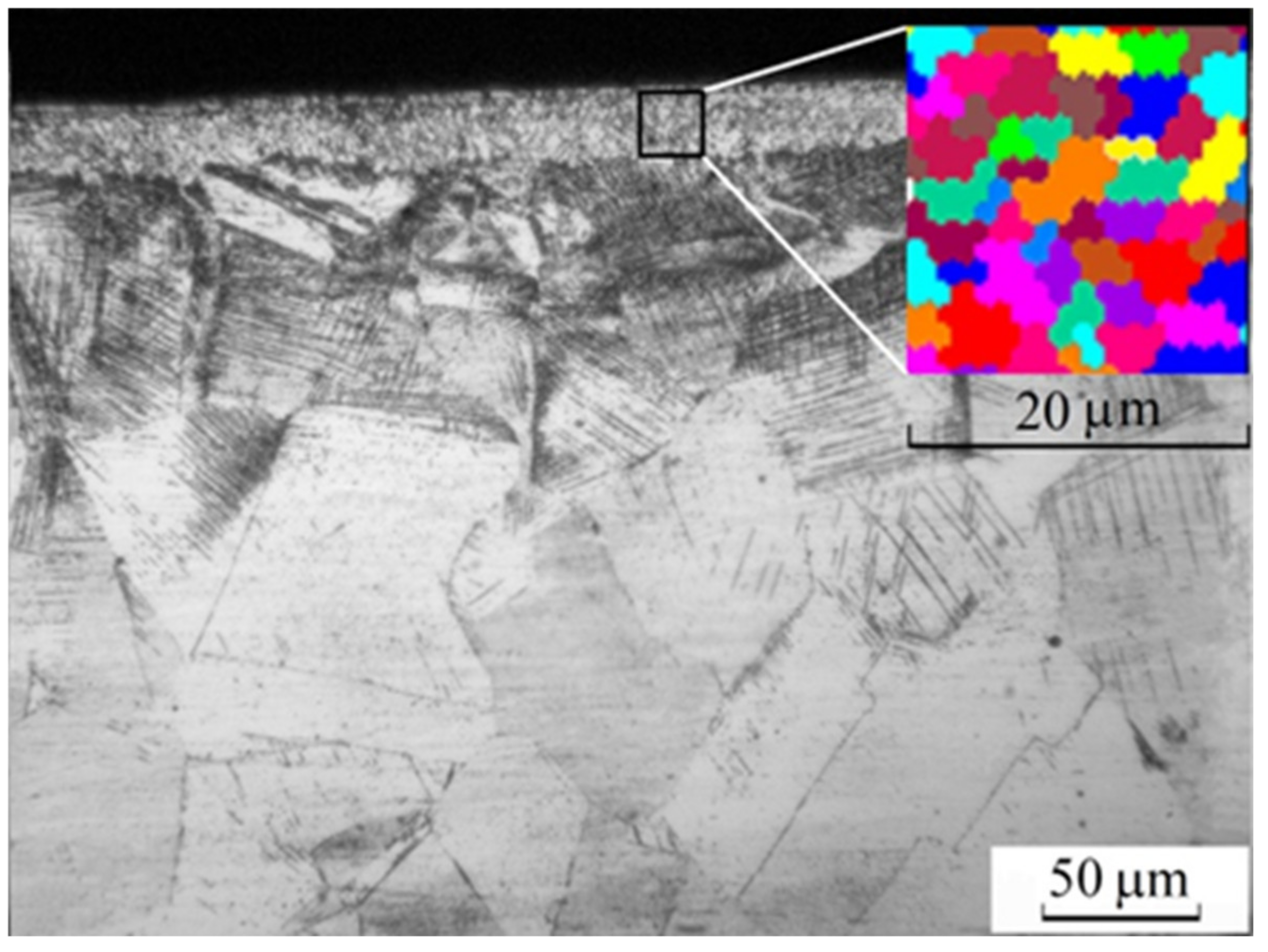
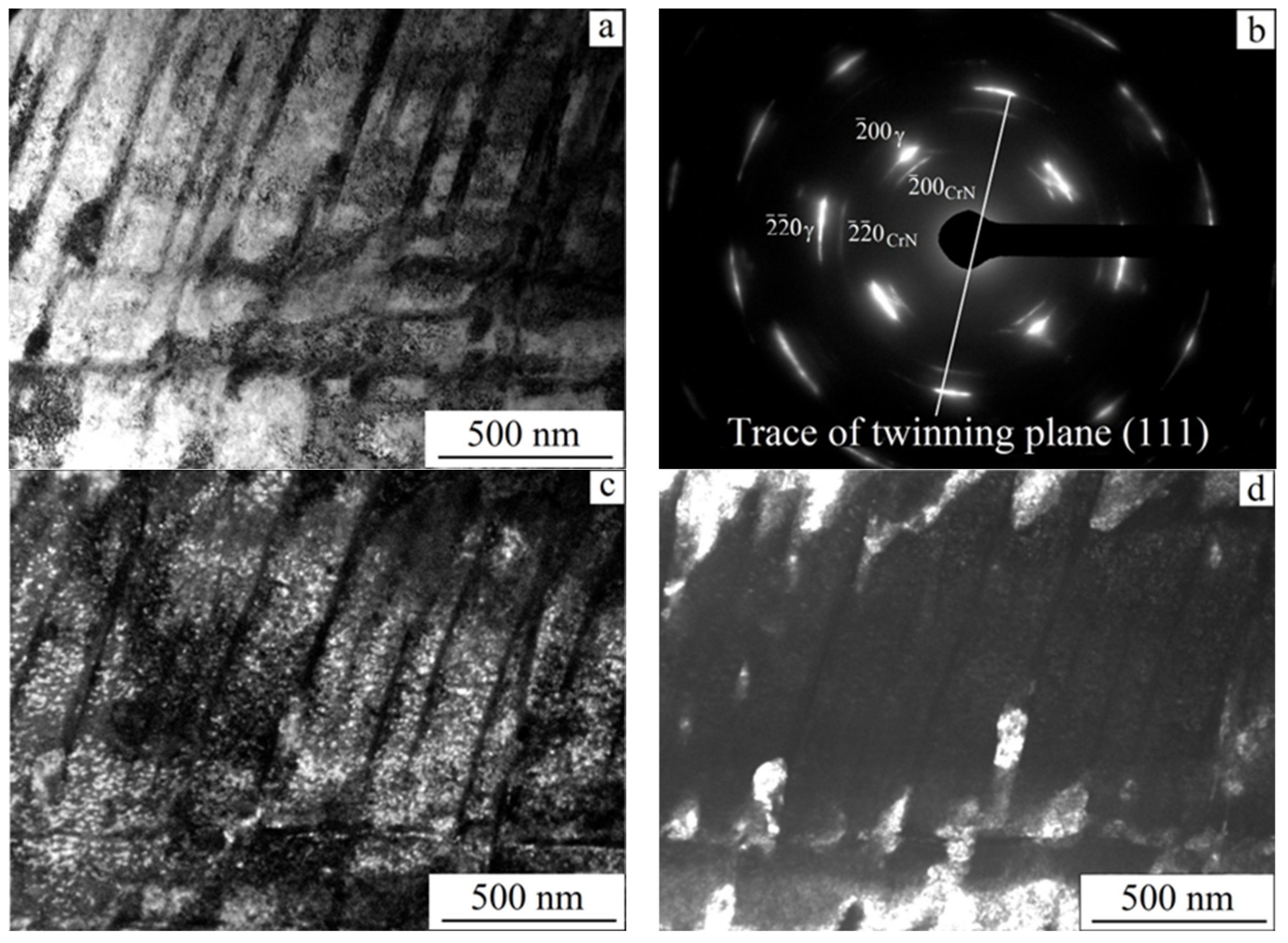
3.1. The Near-Surface Layer Microstructure

Figure 2 shows an OM cross-sectional image of the steel microstructure.
After MTT, the modified near-surface layer with a thickness of 20–25 µm was characterized by an average grain size of 3 µm. In general, such a layer is subjected to frictional loads, so its microstructure and tribological characteristics determine the suitability of a material for orthopedic applications. Below the near-surface layer, another layer was observed that possessed a high density of deformation after twins formation upon friction processing.
As mentioned above, the first MTT stage was friction processing. Its goal was to form a microstructure with the high density of dislocations (Figure 3a), which, upon recrystallization, transformed into a fine-grained one. As followed from an electron diffraction pattern shown in Figure 3b, the crystallographic planes of austenite were curved after friction processing.
The reflections formed arcs with an azimuthal misorientation of up to 20°. In addition to the main reflections, weaker ones of another phase with the FCC lattice were observed. The parallelism of all crystallographic planes of austenite and this phase indicated their coherent relationship. In general, the interplanar distances of an unknown phase could be easily determined using such data of austenite. In the studied case, the most probable phenomenon was strain aging with the formation of CrN particles, characterized by the FCC lattice, the d interplanar distances of 2.07 and 1.46 Å, as well as the lattice parameter of 4.14 Å. Such dispersed CrN particles were distributed in the interlayers between twins (Figure 3c). The parallelism of all crystallographic planes of austenite and the CrN nitride, as well as the similar axes of the [100]γǁ[100]CrN zones (Figure 3b), indicated their coherent relationship. In addition, both austenite and the CrN nitride possessed similar interplanar distances: d(111)γ = 2.08 Å and d(200)CrN = 2.07 Ǻ; d(220)γ = 1.27 Å and d(311)CrN = 1.25 Å. It should be noted that this nitride was also found after cold deformation of the high-nitrogen steel via ultrasonic forging strain processing [27]. Since the nitride lattice volume was larger than that of austenite, it could be formed only in the local regions of tensile stresses. The formation of nitrides in steels with an equilibrium nitrogen content was not observed upon cold rolling.
In friction processing, the plate had been heated up to a temperature within 60 °C. It could be assumed that its levels had been higher in local microvolumes of the surface layer. However, the process duration had excluded the diffusion of both chromium and nitrogen atoms with the formation of nitrides considering the removal of heat to the bulk material. Due to the high and, at the same time, equilibrium content of the alloy elements (especially nitrogen in the FCC lattice), austenite was characterized by great residual stresses in quenched high-nitrogen steels [28]. In the studied case, strain aging had been triggered by internal stresses, while strain heating had been an additional factor. So, the nitride formation process had been the key hardening mechanism, but it had contributed to the relaxation of internal stresses at the same time.
At the second stage, an equilibrium defect-free fine-grained austenitic microstructure with annealing twins was formed (Figure 4a,b).
Its refinement had been facilitated via electron beam processing, characterized by high both heating and cooling rates of about 1010 K/s [29]. This fact had contributed to both recrystallization and precipitation hardening. In this case, the boundary diffusion, required for austenite discontinuous decomposition and Cr2N nitride formation had not occurred. The brightfield image (Figure 4a) shows that the microstructure was completely recrystallized after MTT and contained annealing twins up to 1 µm wide. The contrast in the formation of ripples reflected the austenite inhomogeneity and was characteristic of aging with the formation of particles coherent to the matrix. The electron diffraction pattern (Figure 4b) from area A in Figure 4a reflects the two-phase steel microstructure. The brightest reflections belonged to austenite and formed a grid with the [112]γ zone axis. The reflections of another phase formed a grid with the same axis of the [112]CrN zone, which belonged to CrN nitride. In addition, there were superstructural reflections located at a distance of ½ in the <131> directions that indicated γ phase ordering (the tendency to which was highlighted for the high-nitrogen steels [30,31]).
According to an electron diffraction pattern (Figure 4c) from area B highlighted in Figure 4a, the austenite reflections forms a grid with the [001]γ zone axis. Reflections of another phase (with interplanar distances different from those of austenite) formed a grid, in which one of the reflections had a d interplanar distance of 1.86 Å, close to d(200) = 1.81 Å of austenite. The other two corresponded to the d interplanar distances of 1.4 and 2.055 Å, respectively. The angles calculated between the directions of this grid enabled to conclude that it was orthorhombic. The reflections belonged to Fe2N nitride, which was also found by the authors after ultrasonic forging of the steel surface [27]. Dark-field images of the microstructure in the (200)γ and (121)Fe2N reflections showed the austenite matrix with Fe2N nitrides no larger than 10 nm evenly distributed inside (Figure 4d,e). For comparison, Table 2 presents the tabular [32] and experimental data on the interplanar distances and the angles between the directions of the Fe2N nitride.
Thus, the decomposition of the solid solution supersaturated with nitrogen had occurred upon MTT with the formation of Cr2N particles via the discontinuous mechanism but without an incubation period characteristic of aging. Both nanodispersed FCC CrN nitrides and Fe2N ones with the orthorhombic lattice had been formed in a continuation of strain aging, triggered by frictional processing. After MTT, the microstructure was distinguished by the absence of any discontinuities and the increased proportion of the nitride phases compared to that after friction processing.

3.2. The Tribological Characteristics

During the tribological tests of the Cr-Mn-N steel with the modified near-surface layer, the friction coefficient varied according to the S-type curve shown in Figure 5.
The modified near-surface layer exhibited a low friction coefficient of 0.2 during the tribological test. As it wore out, its level sharply increased by 2.5 times, which characterized the interaction of the counterpart with the bulk steel. Under similar tribological conditions, this stage was absent for both the Ti-6Al-4V alloy and the quenched Cr-Mn-N steel (Figure 5). The obtained experimental results on the tribological behavior of the Ti-6Al-4V alloy agreed with the data reported in [33].
The testing distance, at which the friction coefficient was low, decreased as the load was enhanced. Also, the modified near-surface layer was worn more intensively under greater loads (Figure 6).
The above-described fact should be considered when developing orthopedic implants since their performance depends on both weight and anthropometric features of a human being [2]. Wear resistance of the quenched Cr-Mn-N steel was significantly higher than that of the Ti-6Al-4V alloy (Figure 6). MTT additionally improved this characteristic. In this case, wear of the modified near-surface layer was practically absent at the studied testing distance under the loads within 5 N.
Another feature was a low oscillation amplitude of the friction coefficient during the tribological test of the Cr-Mn-N steel with the modified near-surface layer. Such values reflected the nature of the interaction of the friction surfaces: the smaller the amplitude, the weaker their adhesion. Consequently, the accumulation of damage, as well as the formation of cracks and debris proceeded more slowly in the modified near-surface layer on the Cr-Mn-N steel than those in the Ti-6Al-4V alloy and the quenched Cr-Mn-N steel. In the latter cases, greater amplitudes of oscillations of the friction coefficients of 0.05 and 0.20, respectively, reflected the strong adhesive interaction of the friction surfaces, causing their corrugation in the applied tribological test scheme [34].

3.3. The Mechanical Properties

After MTT, microhardness of the near-surface layer was above 500 MPa (Figure 7). At a depth of 250 µm, this level was almost twice that of the quenched steel. At depths of 80 µm and deeper, microhardness of the modified near-surface layer approached that of the bulk material. According to the authors, the local increase in microhardness in the near-surface layer was associated with the low thermal conductivity of the Cr-Mn-N steel: 24 and 10 W m−1 × K−1 at 800 and 20 °C, respectively. At depths from 20 to 60 µm, the near-surface layer possessed a slightly higher microhardness due to aging of a partially strained microstructure compared to that after friction processing.
It is well known that there is an unambiguous correlation between wear and crack resistances. The higher the crack resistance, the greater is the wear resistance of materials and coatings. As a criterion for crack resistance of a surface subjected to wear, the H/E or H3/E2 ratios are used, where H and E are hardness and the Young’s modulus, respectively [34,35]. In this regard, increasing hardness at a low Young’s modulus contributes to an increase in the H/E or H3/E2 ratios. As followed from the data presented in Table 3, the H/E or H3/E2 ratios significantly enhanced after MTT.
Figure 8 shows the stress–strain curves for the Cr-Mn-N steel after quenching from 1100 °C, friction processing and MTT. In the latter case, the yield point was higher than those after both quenching and friction processing.
The greatest increment in the yield point ΔσYP (in comparison with that of the quenched steel) was obtained via friction processing. The reason for this could be the hardening caused by dislocations Δσd and the formation of nanosized CrN nitrides upon precipitation hardening Δσph with a decrease in the contribution of solid solution hardening Δσsh due to the release of nitrogen from interstitial positions in the FCC lattice: ΔσYP = Δσd + Δσph − Δσsh~150 MPa. After MTT, the Δσ0.2 value was additionally enhanced due to an increase in Δσph contribution because of the increasing volume fraction of the nitrides (that slowed down the movement of dislocations), as well as grain boundary strengthening Δσgb. The effect of aging extended over the entire sample thickness, improving the ultimate tensile strength σUTS. For the surface layer, the additive contribution of all MTT hardening mechanisms reflected the changes in the microstructure compared to that after quenching: ΔσYP = Δσgb + Δσph − Δσsh~190 MPa.
The enhanced yield point was one of the most important parameters that contributed to the improvement in wear resistance of the metallic materials since it additionally increased resistance to shear during friction. Consequently, the probability of both damage accumulation and debris formation reduced in the near-surface layer.

4. Conclusions

For the up-to-date metallic implants used in orthopedics, the main principle of hardening, which provides high both strength properties and wear resistance, is the solid solution alloying. The presence of the dispersed phases is considered undesirable due to the difficulty in controlling their sizes and distribution, as well as a high probability of their chipping. The results of the present study have shown that the precipitation hardening steel, characterized by the necessary both bioinertness and biocompatibility, possessed greater wear resistance as well. The developed surface hardening method, which combines severe plastic deformation and intense (high-rate) heating, has formed the dispersed austenite microstructure. It has been straightened with the nanosized CrN and Fe2N nitrides, whose uniform distribution in grains and coherent bonding with the matrix prevent the formation of wear debris. During the tribological test of the modified near-surface layer, a distinctive feature has been the low friction coefficient of 0.2. In addition, MTT has almost doubled the microhardness of the near-surface layer and enhanced the yield point. The disadvantage of the investigated Cr-Mn-N steel is the high Young’s modulus, the value of which is almost two times greater than that of the Ti-6Al-4V alloy and more than three times above that of human bone tissues.

Author Contributions

Conceptualization, N.N.; validation, N.N.; writing—original draft preparation, N.N.; writing—review and editing, N.N., I.V. and A.T.; investigation, I.V. and A.T. All authors have read and agreed to the published version of the manuscript.

Funding

The work was performed according to the Government research assignment for ISPMS SB RAS, project No. FWRW-2021-0009.

Data Availability Statement

Not applicable.

Acknowledgments

The TEM investigations were conducted using the equipment of Krasnoyarsk Regional Center of Research Equipment of Federal Research Center «Krasnoyarsk Science Center SB RAS».

Conflicts of Interest

The authors declare no conflict of interest.

References

  1. Tigani, D.; Fosco, M.; Bena Ayad, R.; Fantasia, R. Orthopaedic Implant Materials and Design. In Wear of Orthopaedic Implants and Artificial Joints; Affatato, S., Ed.; Woodhead Publishing: Cambridge, UK, 2012; pp. 133–177. [Google Scholar]
  2. Zhidkov, A.V.; Pashmentova, A.S.; Viun, S.S.; Zhiltsov, M.P.; Mishin, V.V.; Podmasteryev, K.V. The mathematical simulation and study of the electrical resistance of the friction zone of the hip joint endoprosthesis with a metal-metal friction pair. Frict. Wear 2018, 39, 251–258. [Google Scholar] [CrossRef]
  3. Wu, Y.; Wang, Y.; Liu, M.; Shi, D.; Hu, N.; Feng, W. Mechanical Properties and in Vivo Assessment of Electron Beam Melted Porous Structures for Orthopedic Applications. Metals 2023, 13, 1034. [Google Scholar] [CrossRef]
  4. Lang, Y.; Qu, H.; Chen, H.; Weng, Y. Research progress and development tendency of nitrogen-alloyed austenitic stainless steels. J. Iron Steel Res. Int. 2015, 22, 91–98. [Google Scholar] [CrossRef]
  5. Sumita, M.; Hanawa, T.; Teoh, S.H. Development of nitrogen-containing nickel-free austenitic stainless steels for metallic biomaterials—Review. Mater. Sci. Eng. C 2004, 24, 753–760. [Google Scholar] [CrossRef]
  6. Ren, Y.; Wan, P.; Liu, F.; Zhang, B.; Yang, K. In vitro study on a new high nitrogen nickel-free austenitic stainless steel for coronary stents. J. Mater. Sci. Technol. 2011, 27, 325–331. [Google Scholar] [CrossRef]
  7. Li, M.; Yin, T.; Wang, Y.; Du, F.; Zou, X.; Gregersen, H.; Wang, G. Study of biocompatibility of medical grade high nitrogen nickel-free austenitic stainless steel in vitro. Mater. Sci. Eng. C 2014, 43, 641–648. [Google Scholar] [CrossRef]
  8. Yamamoto, A.; Kohyama, Y.; Kuroda, D.; Hanawa, T. Cytocompatibility evalution of Ni-free stainless steel manufactured by nitrogen adsorption treatment. Mater. Sci. Eng. C 2004, 24, 737–743. [Google Scholar] [CrossRef]
  9. Ma, T.; Wan, P.; Cui, Y.; Zhang, G.; Li, J.; Liu, J.; Ren, Y.; Yang, K.; Lu, L. Cytocompatibility of high nitrogen stainless steel for orthopedic implants. J. Mater. Sci. Technol. 2012, 28, 647–653. [Google Scholar] [CrossRef]
  10. Talha, M.; Behera, C.K.; Sinha, O.P. Promising in vitro performances of nickel-free nitrogen-containing stainless steels for orthopaedic applications. Bull. Mater. Sci. 2014, 37, 1321–1330. [Google Scholar] [CrossRef]
  11. Muley, S.V.; Vidvans, A.N.; Chaudhari, G.P.; Udainiya, S. An assessment of ultra fine grained 319L stainless steel for implant application. Acta Biomater. 2016, 30, 408–419. [Google Scholar] [CrossRef]
  12. Kaur, M.; Singh, K. Review on titanium and titanium based alloys as biomaterials for orthopaedic applications. Mater. Sci. Eng. C 2019, 102, 844–862. [Google Scholar] [CrossRef] [PubMed]
  13. He, Z.; He, H.; Lou, J.; Li, Y.; Li, D.; Chen, Y.; Liu, S. Fabrication, Structure and Mechanical and Ultrasonic Properties of Medical Ti6Al4V Alloys Part I: Microstructure and Mechanical Properties of Ti6Al4V Alloys Suitable for Ultrasonic Scalpe. Materials 2020, 13, 478. [Google Scholar] [CrossRef] [PubMed] [Green Version]
  14. Revankar, G.D.; Shetty, R.; Rao, S.S.; Gaitonde, V.N. Wear resistance enhancement of titanium alloy (Ti–6Al–4V) by ball burnishing process. J. Mater. Res. Technol. 2017, 6, 13–32. [Google Scholar] [CrossRef] [Green Version]
  15. Wang, Z.; Liu, Z.; Gao, C.; Wong, K.; Ye, S.; Xiao, Z. Modified wear behavior of selective laser melted Ti6Al4V alloy by direct current assisted ultrasonic surface rolling process. Surf. Coat. Technol. 2020, 381, 125122. [Google Scholar] [CrossRef]
  16. Panin, A.; Kazachenok, M.; Krukovskii, K.; Buslovich, D.; Kazantseva, L.; Martynov, S.; Sklyarova, E. Transformations of the Microstructure and Phase Compositions of Titanium Alloys during Ultrasonic Impact Treatment Part III: Combination with Electrospark Alloying Applied to Additively Manufactured Ti-6Al-4V Titanium Alloy. Metals 2023, 13, 932. [Google Scholar] [CrossRef]
  17. Feng, S.; Tang, H.; Zhang, S.; Wang, H. Microstructure and wear resistance of laser clad TiB–TiC/TiNi–Ti2Ni intermetallic coating on titanium alloy. Trans. Nonferr. Met. Soc. China 2012, 22, 1667–1673. [Google Scholar] [CrossRef]
  18. Cui, W.; Qin, G.; Duan, J.; Wang, H. A graded nano-TiN coating on biomedical Ti alloy: Low friction coefficient, good bonding and biocompatibility. Mater. Sci. Eng. C 2017, 71, 520–528. [Google Scholar] [CrossRef]
  19. Tao, X.; Li, X.; Dong, H.; Matthews, A.; Leyland, A. Evaluation of the sliding wear and corrosion performance of triode-plasma nitrided Fe-17Cr-20Mn-0.5N high-manganese and Fe-19Cr-35Ni-1.2Si high-nickel austenitic stainless steels. Surf. Coat. Technol. 2021, 409, 126890. [Google Scholar] [CrossRef]
  20. Tao, X.; Rainforth, M.; Matthews, A.; Leyland, A. On the interstitial induced lattice inhomogeneities in nitrogen-expanded austenite. Scr. Mater. 2020, 185, 146–151. [Google Scholar] [CrossRef]
  21. Narkevich, N.A.; Surikova, N.S.; Mironov, Y.P.; Perevalova, O.B.; Shugurov, A.R.; Shulepov, I.A.; Durakov, V.G.; Mel’nikov, A.G.; Narkevich, V.V. Structure and lattice strains in the surface Cr–Mn–N steel formed by a combination of friction and electron-beam treatments. Phys. Met. Metallogr. 2019, 120, 1071–1077. [Google Scholar] [CrossRef]
  22. Korshunov, L.G.; Goikhenberg, Y.N.; Chernenko, N.L. Effect discontinuous decomposition on the tribologic properties of high nitrogen chromium manganese austenitic steel G22KH18A0.80. Phys. Met. Metallogr. 2000, 90, 192–198. [Google Scholar]
  23. Qiao, Y.; Wang, X.; Yang, L.; Wang, X.; Chen, J.; Wang, Z.; Zhou, H.; Zou, J.; Wang, F. Effect of aging treatment on microstructure and corrosion behavior of a Fe-18Cr-15Mn-0. 66N stainless steel. J. Mater. Sci. Technol. 2022, 107, 197–206. [Google Scholar] [CrossRef]
  24. Narkevich, N.A.; Mironov, Y.P.; Shulepov, I.A. Structure, mechanical and tribotechnical properties of an austenitic nitrogen steel after frictional treatment. Phys. Met. Metallogr. 2017, 118, 399–406. [Google Scholar] [CrossRef]
  25. Panin, V.E.; Beljuk, S.I.; Durakov, V.G.; Pribytkov, G.A.; Rempe, N.G. Electron beam vacuum surfacing: Equipment, technology and properties of coatings. Weld. Int. 2000, 14, 580–584. [Google Scholar] [CrossRef]
  26. Shil’ko, S.V.; Chernous, D.A.; Panin, S.V. Modeling of bionically inspired antifriction and connecting layers in a joint endoprosthesis. Phys. Mesomech. 2023, 26, 93–99. [Google Scholar] [CrossRef]
  27. Narkevich, N.A.; Deryugin, E.E.; Perevalova, O.B.; Vlasov, I.V. Effect of ultrasonic forging strain processing on the nearsurface layer microstructure and temperature-dependent mechanical properties of high nitrogen austenitic steel. Mater. Sci. Eng. A 2022, 834, 142590. [Google Scholar] [CrossRef]
  28. Narkevich, N.; Vlasov, I.; Volochaev, M.Y.; Mironov, Y.; Panin, S.; Berto, F.; Pavel Maksimov, P.; Deryugin, E. Low-Temperature Deformation and Fracture of Cr-Mn-N Stainless Steel: Tensile and Impact Bending Tests. Metals 2023, 13, 95. [Google Scholar] [CrossRef]
  29. Ormanova, M.; Petrov, P.; Kovacheva, D. Electron beam surface treatment of tool steels. Vacuum 2017, 135, 7–12. [Google Scholar] [CrossRef]
  30. Mittemeher, E.J.; Cheng, L.; Van der Schaaf, P.J.; Brakman, C.M.; Korevaar, B.M. Analysis of nonisothermal transformation kinetics; tempering of iron–carbon and iron–nitrogen martensites. Metall. Trans. A 1988, 19, 925–932. [Google Scholar] [CrossRef]
  31. Kim, J.-M.; Kim, S.-J.; Kang, J.-H. Effects of short-range ordering and stacking fault energy on tensile behavior of nitrogen-containing austenitic stainless steels. Mater. Sci. Eng. A 2022, 836, 142730. [Google Scholar] [CrossRef]
  32. International Centre for Diffraction Data (ICDD), USA. 2020. Available online: http://www.icdd.com/ (accessed on 1 January 2022).
  33. Ryu, J.J.; Shrestha, S.; Manogharan, G.; Jung, J.K. Sliding Contact wear damage of EBM built Ti6Al4V: Influence of process induced anisotropic microstructure. Metals 2018, 8, 131. [Google Scholar] [CrossRef] [Green Version]
  34. Tagil’tseva, D.N.; Narkevicha, N.A.; Shulepov, I.A.; Moiseenko, D.D. Relaxation capacity and cracking resistance of nitrous coating produced by electron-beam facing of 0.6C–24Cr–1N–16Mn steel powder during wear by hard abrasive under heavy loads. J. Frict. Wear 2014, 35, 104–110. [Google Scholar] [CrossRef]
  35. Leyland, A.; Matthews, A. On the significance of the H/E ratio in wear control: Nanocomposite coating approach to optimised tribological behavior. Wear 2000, 246, 1–11. [Google Scholar] [CrossRef]
  36. Ojima, M.; Adachi, Y.; Tomota, Y.; Ikeda, K.; Kamiyama, T.; Katada, Y. Work hardening mechanism in high nitrogen austenitic steel studied by in situ neutron diffraction and in situ electron backscattering diffraction. Mater. Sci. Eng. A 2009, 527, 16–24. [Google Scholar] [CrossRef]
Figure 1. The cutting scheme and the dimensions of the specimens for the tensile tests (in millimeters).
Metals 13 01328 g001
Figure 2. The OM cross-sectional image of Cr-Mn-N steel microstructure after MTT. (Marked fragment shows the grain size of the near-surface layer.)
Metals 13 01328 g002
Figure 3. The microstructure of the near-surface layer of Cr-Mn-N steel after friction processing as (a) brightfield image; (b) electron diffraction pattern with the Feγ and CrN reflection grids: z = [001]γ, z = [001]CrN; (c) darkfield image in the ( 2 ¯ 00)CrN reflection; (d) darkfield image in the ( 2 ¯ 00)γ reflection.
Metals 13 01328 g003
Figure 4. The microstructure of the near-surface layer on Cr-Mn-N steel after friction and subsequent electron beam processing: (a) brightfield image; (b) electron diffraction pattern from area A, highlighted in (a), with the Feγ and CrN reflection grids: z = [112]γ, z = [112]CrN; (c) electron diffraction pattern from area B, highlighted in (a), with the Feγ and Fe2N reflection grids: z = [001]γ, z = [ 5 ¯ 3 1 ¯ ]Fe2N; (d) darkfield image in the (200)γ reflection; (e) darkfield image in the (121)Fe2N reflection.
Metals 13 01328 g004
Figure 5. Changes in the k friction coefficients in the tribological tests after 1—quenching from 1100 °C; 2 and 3—friction and subsequent electron beam processing; 4—for Ti-6Al-4V alloy as a reference. The load was 5 N for curves 1, 3, and 4, but it was 2 N for curve 2.
Metals 13 01328 g005
Figure 6. Changes in the wear rates in the tribological tests according to the 94%WC-6%Co hard-alloy ball on Cr-Mn-N steel disk scheme after 1—quenching from 1100 °C; 2—friction and subsequent electron beam processing; 3—for Ti-6Al-4V alloy as a reference.
Metals 13 01328 g006
Figure 7. The in-depth microhardness distribution for Cr-Mn-N steel after 1—friction processing; 2—friction and subsequent electron beam processing.
Metals 13 01328 g007
Figure 8. The stress strain curves for Cr-Mn-N steel after 1—quenching from 1100 °C; 2—friction processing; 3—friction and subsequent electron beam processing.
Metals 13 01328 g008
Table 1. Chemical composition of the studied materials in weight, %.
ElementCrMnSiNiCNPSAlVTiFe
Cr-Mn-N steel16.518.810.520.240.070.530.010.001---Bal.
Ti-6Al-4V--0.07-0.070.05--5.83.92Bal.-
Table 2. The interplanar distances and the angles between the directions in the Fe2N orthorhombic lattice: comparison of the obtained experimental data with the ICDD file [32].
Phase,
Lattice Type
Planes (hkl)Interplanar
Distances d Å
Angles between
Directions φ, Grad
Lattice
Parameters, Å
Lattice
Volume V, Å3
Fe2Nexp,
orthorhombic
(013)1.40(013) (121) 48a = 6.147
b = 5.034
c = 4.367
135.13
(121)2.055(013) ( 1 ¯ 1 ¯ 2 ) 42
( 1 ¯ 1 ¯ 2 )1.86( 1 ¯ 1 ¯ 2 ) (121) 90
Fe2NICDD,
orthorhombic
(013)1.41(013) (121) 48a = 5.523
b = 4.83
c = 4.425
118.02
(121)1.98(013) ( 1 ¯ 1 ¯ 2 ) 45
( 1 ¯ 1 ¯ 2 )1.89( 1 ¯ 1 ¯ 2 ) (121) 93.5
Table 3. The H hardness and E Young’s modulus values, as well as H/E or H3/E2 ratios of the Cr-Mn-N steel after quenching and subsequent MTT.
ProcessingH, GPaE, GPaH/EH3/E2
Quenchig
Quenchig + MTT
3
5
200 [36]1.5 × 10⁻²
2.5 × 10⁻²
6.75 × 10⁻⁴
31.25 × 10⁻⁴
Disclaimer/Publisher’s Note: The statements, opinions and data contained in all publications are solely those of the individual author(s) and contributor(s) and not of MDPI and/or the editor(s). MDPI and/or the editor(s) disclaim responsibility for any injury to people or property resulting from any ideas, methods, instructions or products referred to in the content.

