
The Influence of Two-Jet Gas Shielding Parameters on the Structure and Microhardness of Steel 45 Joints during Consumable Electrode Welding

1
Faculty of Aircraft Engineering, Novosibirsk State Technical University, Novosibirsk 20 K. Marksa Prospekt, 630073 Novosibirsk, Russia
2
Yurga Technological Institute, National Research Tomsk Polytechnic University, 30 Lenina Prospekt, 634050 Tomsk, Russia
3
Institute of Strength Physics and Materials Science of Siberian Branch Russian Academy of Sciences, 2/4 Akademicheskiy Prospekt, 634055 Tomsk, Russia
*
Author to whom correspondence should be addressed.
Metals 2023, 13(6), 1136; https://doi.org/10.3390/met13061136
Submission received: 25 April 2023
/
Revised: 13 June 2023
/
Accepted: 16 June 2023
/
Published: 18 June 2023
Abstract
:The paper presents the study results of the parameters influence of arc welding with a consumable electrode with two-jet gas shielding in CO2 on the structure and microhardness of high-strength steel 45 welded joints with slotted edges. Controlling the dynamic impact of the internal shielding gas jet on the processes in the welding zone changes the heat and mass transfer processes in the welding zone and results in the intensive mixing of the molten electrode metal with the base metal in the weld pool. The results of the studies determined the dynamic effect of the active shielding gas jet on the structure and microhardness of multilayered steel 45 welded joints with slotted edges using the method of full factorial experiment, developed dependences of chemical elements (carbon, silicon, manganese) content in the weld metal of multilayered steel 45 welded joints on the controlled parameters of the welding mode (Q, Iw, U). Due to uneven heat introduction into each of the welded plates during edge slotting, the asymmetric distribution of microhardness in the cross sections of welded joints relative to the weld axis indicates some differences in the structure and properties of the heat-affected zone (HAZ) and the weld. According to the results of the studies, consumable electrode arc welding with two-jet gas shielding provides faster distribution and equalization of heat on the product surface and reduces its instantaneous overheating, which improves the structural phase state of the welded joint made of steel 45 and reduces the microhardness gradient in the HAZ. An increase in the heat input of welding (a simultaneous increase in the welding current and voltage of the welding arc) leads to a decrease and smoothing of the microhardness peak in the HAZ.
1. Introduction
Welding is used to connect various materials in the conditions of the earth’s atmosphere, ocean, and space and remains one of the main technological processes for the production of metal structures and equipment. Steel is still the main structural material, despite the constant increase in the share of light alloys, composites, and polymeric materials in modern products. The demand for the production of welded metal structures, especially from high-strength steel, is constantly increasing, not only in mechanical engineering, but also in other industries [1,2,3,4,5].
High-strength steels have a set of operational properties and are used for the production of critical welded metal structures because they provide high-strength of structures while reducing their metal consumption. However, the welding process in this class of steel results in hardening structures in the heat-affected zone (HAZ). These structures have a high hardness and internal tension gradient that can lead to the development of cold cracks and the dissolution of a permanent joint. Welding processes are influenced by various phenomena and factors that determine their quality and operational reliability [2,3,4]. The process of welding with a consumable electrode in shielding gases is always accompanied by an extreme change of the material in the welding zone and inevitable losses-burnout and oxidation of chemical elements, splashing droplets of molten metal of the welding wire. The fluctuation of the welding arc and the decrease in the stability of the welding process increase the level of random losses of material and chemical elements during the transition from the electrode to the weld, which reduces the predictability, repeatability, and stability of the chemical composition and properties of welded joints from steels prone to hardening, including the HAZ hardness value [3,4,5].
The level of structural and mechanical inhomogeneity in the metal of the welded joint can be reduced by intensive mixing of the electrode metal with the base metal and by controlling the thermal cycle of welding [4,5]. A longer time spent in the molten state in the weld pool improves the mixing of the electrode metal and base metal but also increases the possibility that the weld metal becomes saturated with hydrogen, which can cause embrittlement [3,4] and ensure overheating of the base metal in the HAZ.
Reducing the time of the drop’s molten metal and the weld pool being in the liquid phase and, at the same time, increasing the rate of their mixing can be achieved by using pulsed or dynamic effects, such as programmable controlled transfer of the electrode metal into the weld pool [6,7,8], controlled dynamic effect of the shielding gas jet on the processes in the welding zone [7,9,10,11,12,13,14,15,16,17], etc.
The authors of works [8,9,10,11,12,13,14,15,16,17,18,19,20,21,22,23,24,25] researched the effect of changing shielding gas flows on the consumable electrode welding process and noted that an increase in the gas outflow rate improves the quality of the welding zone shielding, the formation of the weld, and the stability of the welding process.
Works [20,21,22] argue that using an alternate supply of shielding gases (Ar, He) when welding with a consumable electrode increases the stability of the welding process as well as the formation and density of welds. The shielding gas supply rate affects the transfer of electrode metal droplets and contributes to the separation and transfer of droplets to the weld pool. The authors of [18,19] suggest that the control of shielding gas dynamics is a promising method for improving the technology of consumable electrode welding in shielding gases.
Some studies offer using small diameter nozzles for narrow gap welding while maintaining the recommended gas flow rate for standard torches [14,15,16,17] with two-layer shielding using two different gases (Ar, CO2) [12,24] or two-jet gas shielding, which requires two coaxial jets of one gas and one common chamber [4,25]. These parameters provide reliable shielding of the weld pool compared with the single-jet (traditional) method, increase the stability and frequency of droplet transfer from the electrode to the weld pool, refine the weld metal structure, smooth transition from the weld metal to the base metal, improve the mechanical properties of welded joints, and reduce the chemical heterogeneity of the weld metal due to a positive gas-dynamic effect on the processes in the welding zone and more intensive mixing of the molten metal in the weld pool.
The authors of works [9,10,11,12,13,14,15,16,17,18,19,20,21,22,23,24,25] investigated how shielding gas flow dynamics affected consumable electrode welding processes and discovered that an increase in the gas flow rate from the welding nozzle improves the quality of the welding zone shielding and the formation of the weld seam, as well as increases the stability of the welding process. A decrease in the electrode wire stick-out increases the microhardness because the density and flow rate of the shielding gas also increase (at a constant flow rate), which in turn increases the cooling rate of the metal under the welding nozzle and thus the microhardness in the HAZ.
To assess the effect of welding parameters and the dynamics of two-jet gas shielding on the structure and microhardness of welded joints made of steel 45, a comprehensive study was carried out.
2. Methodology
Shielding gas arc welding is based on the principle of air displacement from the welding zone by a shielding gas flow. The following methods of shielding gas supply are most widely used: single-jet shielding, general shielding in chambers, and double-layer shielding with two coaxial jets of different gases.
For shielding gas environments, inert gases (argon, helium), active gases (nitrogen and CO2), and their mixtures are used. The properties of shielding gases have a great influence on the technological properties of the arc and the shape of the welds.
Jet shielding is one of the most common methods of local shielding in welding. The rate of crystallization of the weld metal is controlled by the flow rate of the shielding gas and the distance from the nozzle exit to the surface of the welded metal [7,26,27]. Only the melting zone is exposed to gas jet shielding during welding. With local jet shielding, the gas flow is laminar, but as the shielding gas outflow rate approaches a critical value, the laminar flow transforms into a turbulent one with strong eddies. At the same time, up to 50% of air is mixed into the shielding gas jet at a distance of several millimeters (6–10 mm) [27].
The shielding properties of the gas jet mainly depend on the properties of the gas used [26] and the gas-dynamic parameters of its outflow from the nozzle of the welding torch [25,26,27].
- -
- high concentration of arc energy and its penetration ability, which provides a smaller zone of temperature influence and high welding performance;
- -
- higher efficiency of the process;
- -
- the 4 times lower cost of shielding gas (per liter) than that of argon and its mixtures;
- -
- resistance to the formation of cracks and pores, which is ensured by reliable active gas shielding in the welding zone;
- -
- the possibility of visual observation of weld formation;
- -
- high mobility and maneuverability of the process which allows for the welding of any complexity in different spatial positions;
- -
- the possibility of automating the entire welding cycle.
With such advantages, the method of welding in CO2 has some disadvantages. The main disadvantage of this method is the unstable transfer of the electrode metal drops into the weld pool, which increases the electrode metal spatter [7,26,27] and the range of the obtained weld metal properties [7].
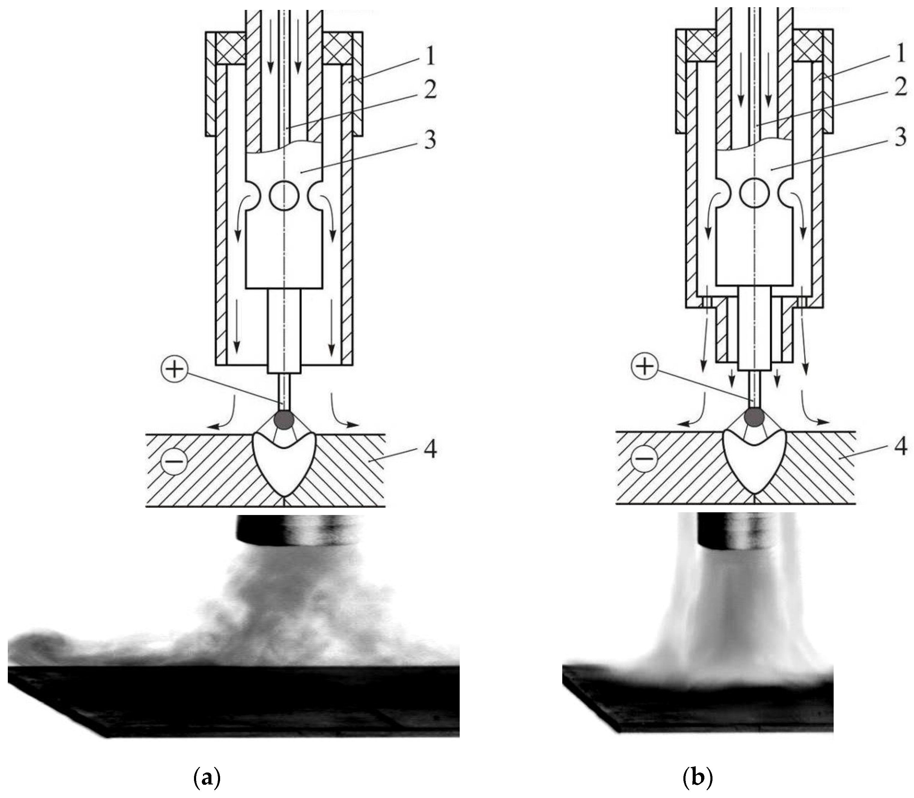
A two-jet welding nozzle provides better gas shielding of the melting zone than a single-jet (Figure 1b). Two-jet shielding employs two coaxial jets of one gas and one common chamber. In this case, the external annular gas flow presses the gas front reflected from the surface of the workpiece to be welded [4,28]. Thus, the formed shielding gas flow becomes more stable and covers the maximum of the welded product surface.
Two-jet gas shielding during consumable electrode welding [4,25,28] ensures the stability of the internal jet of the supplied gas, reliable welding zone shielding, and reduces eddies in the HAZ. Controlling the dynamic impact of the internal shielding gas jet on the processes in the welding zone changes the heat and mass transfer processes in the welding zone and results in the intensive mixing of the molten electrode metal with the base metal in the weld pool. The increased rate of gas (CO2) outflow reduces the time of weld metal and the HAZ exposure to the high temperature. The external annular jet blocks eddies near the surface of the welded workpiece and provides reliable shielding of the welding zone from the harmful effects of air.
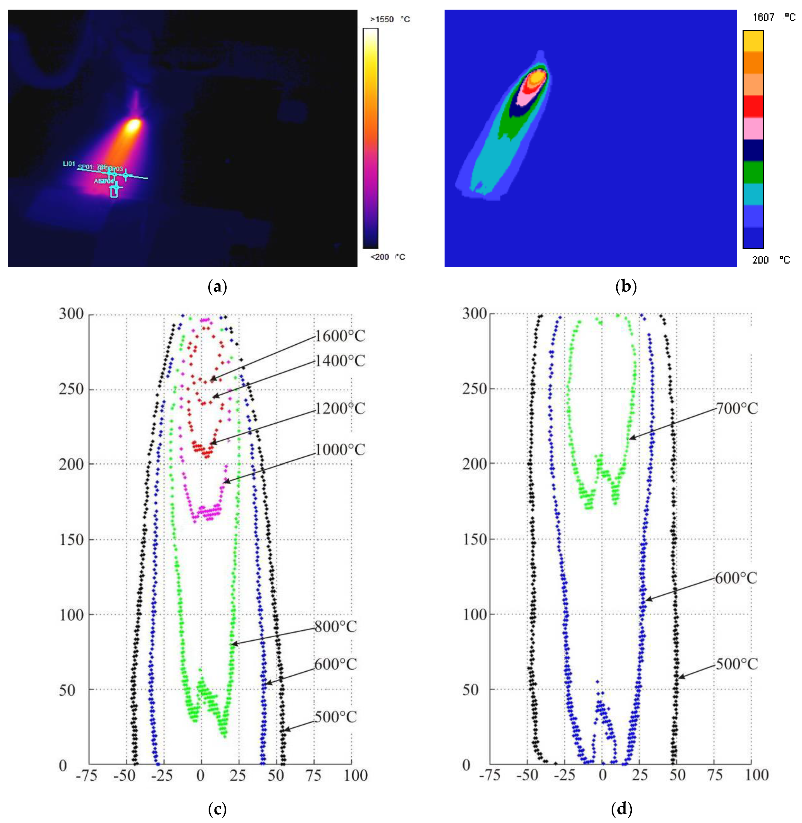
To assess the change in heat distribution and thermal cycle on the surface of welded joints from the conditions of gas shielding (CO2) during consumable electrode welding, experiments were carried out using ThermaCAM P65HS thermal imaging equipment from FLIR Systems (USA).
The welding modes were the same for two-jet and single-jet gas shielding. In all experiments, video recording was carried out during the welding time of one pass (60 s) and for 60 s after the end of welding at a frequency of 5 frames/s. This yielded the images of temperature fields (thermograms) of the welded item heating (t = 60 s) and cooling (t = 120 s) (Figure 2).
Based on the results of the obtained thermogram analysis, thermal cycles were constructed for three points located 10 mm from the beginning of the welded plates in a butt weld without edge preparation (along the X axis): along the weld axis Y = 0 cm, at a distance Y = 0.5 cm from the weld axis, and at a distance Y = 1.4 cm from the weld axis (Figure 3).
The results of the thermogram analysis demonstrate that the thermal cycles of the weld metal and the HAZ of welded joints are not the same: in the range of about 770–790 °C there is an equalization of temperatures and before that, the hotter weld metal becomes less hot compared to the metal of the HAZ with any method of gas shielding. The rate of temperature saturation in welded plates with two-jet gas shielding is slightly higher, and the temperature equalization between the weld metal and the HAZ occurs 1–1.4 s earlier than with single-jet gas shielding. The temperature rise in front of the heating source with single-jet gas shielding is faster.
The method of a full factorial experiment was applied to determine the dynamic effect of the shielding gas and the technological parameters of two-jet gas shielding during welding on the structure and microhardness of welded joints made of high-strength steel 45 (Table 1). The experimental conditions included mechanized multipass welding of plates made of 45 steel with a size of 150 mm × 300 mm and a thickness of 10 mm; slotted preparation of edges (grooving width is 8 mm) with welding wire Sv-08G2S with a diameter of 1.2 mm; a stationary arc with two-jet gas shielding (CO2) without preheating and subsequent heat treatment.
Three controllable factors (x1—Q, x2—Iw, and x3—U) were studied using the full factorial experiment method. Controlled parameters varied at two levels: welding current Iw1 = 170 A and Iw2 = 200 A, arc voltage U1 = 26 V and U2 = 29 V, and shielding gas flow rate Q1 = 25 L/min and Q2 = 30 L/min. Electrode stick out L = 12 mm, welding speed V = 24–25 cm/min. VS-300B power source, GSP-2 automatic welding head, BARS-2B automatic welding control unit.
For the experiments, a planning matrix for a full factorial experiment was compiled (Table 2).
3. Research Results
The chemical composition of the welded joints metal is presented in Table 3.
The research results provide the basis for developing the dependence of the welding mode controlled parameters(Q, Iw, U) effect on the chemical elements(carbon, silicon, manganese) the content in the weld metal of the multilayer welded joints made of steel 45. The controlled parameters are presented as dimensionless quantities (x1—Q, x2—Iw, x3—U) varying in the range from –1 to +1. In this case, the relative calculation error does not exceed 10%:
1. The regression dependence of carbon content on the controlled parameters. The full factorial experiment’s findings demonstrate that the welding mode’s controlled parameters (Q, Iw, and U) have no effect on the carbon content of multilayer welded joints made of steel 45, though there is a barely perceptible dependence on the welding current:
2. The regression dependence of silicon content on the controlled parameters.
3. The regression dependence of manganese content on the controlled parameters.
It has been determined that the amount of silicon and manganese in the weld metal reduces as the shielding gas (CO2) consumption rises. Manganese and silicon levels in the weld metal decrease as the welding arc voltage increases. The amount of manganese in the weld metal increases when the welding current is increased within the chosen range. Under the conditions of this experiment, the regulated welding mode parameters (Q, Iw, U) had no effect on the carbon content of multilayer welded joints made of steel 45.
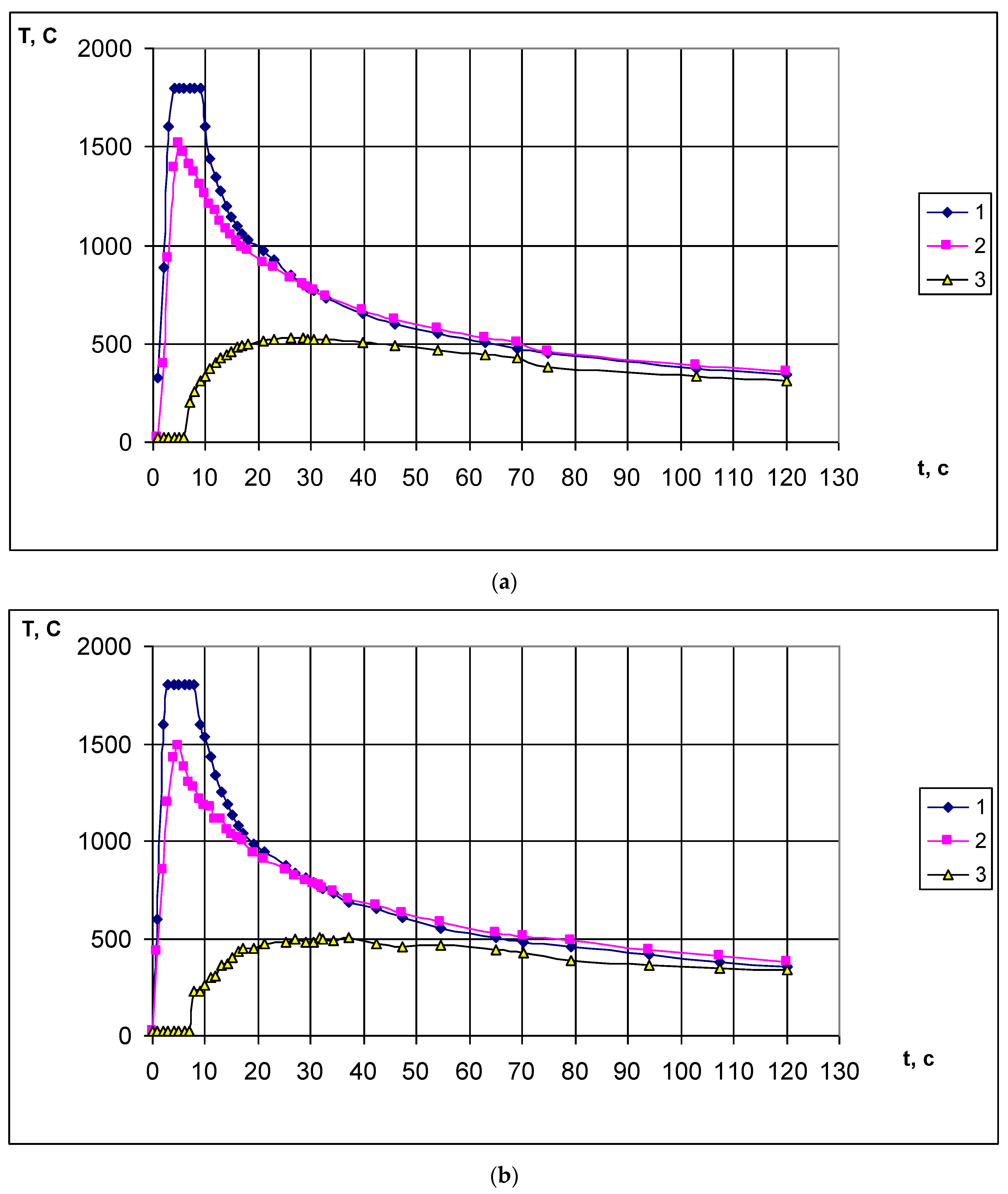
Microhardness measurements were conducted along the lines located at a distance of 2 and 4 mm from the upper surface of the welded samples (Figure 4) to determine the influence of the selected welding mode-controlled parameters (Q, Iw, U) on the change in the distribution of microhardness in the cross-section of the welded joints. Duramin-5 microhardness tester was used for the measurements.
In the HAZ, there is a dramatic increase in microhardness according to an analysis of the microhardness distribution in the cross sections of the welded joints. The microhardness values of the weld metal are spread between 190 and 250 HV and are about the same in all layers, matching the microhardness of the base metal. Welding arc oscillations and slight variations in the chemical composition of the base metal plates may result in non-uniform heat introduction into each of the welded plates, which leads to an asymmetric distribution of microhardness in the sections of welded joints relative to the axis of the weld (Figure 5). The proximity of the plates’ walls increases the oscillations and deviations of the arc while welding slotted edges.
The fusion zone of multilayer welded joints made of steel 45 has been found to contain a microhardness peak (300–420 HV). The size of the microhardness peak decreases along the depth of the slotted groove because of automatic heat treatment with a subsequent layer. A simultaneous increase in the welding current and voltage of the welding arc (an increase in the heat input of welding) leads to a decrease and smoothing of the microhardness peak (samples 7 and 8 in Figure 4).
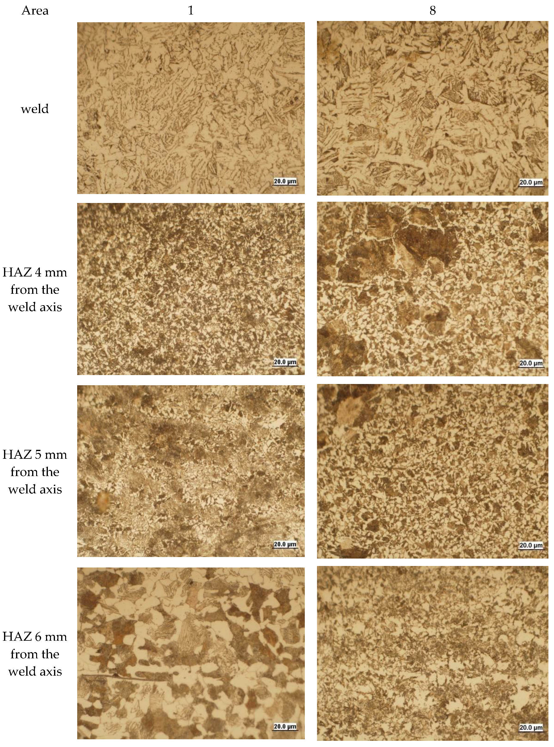
Figure 5 displays the microstructure of the zones of welded joints produced by welding modes 1 and 8 in the full factorial experiment.
The analysis of the microstructure of the samples shown in Figure 5 revealed that they differ slightly in the corresponding sections; the structure of sample 8 has a larger and coarser structure, and there is a displacement of the welded joint zones toward the base metal compared with sample 1. This can be explained by an increase in welding arc voltage and welding current, i.e., by an increase in the amount of introduced heat.
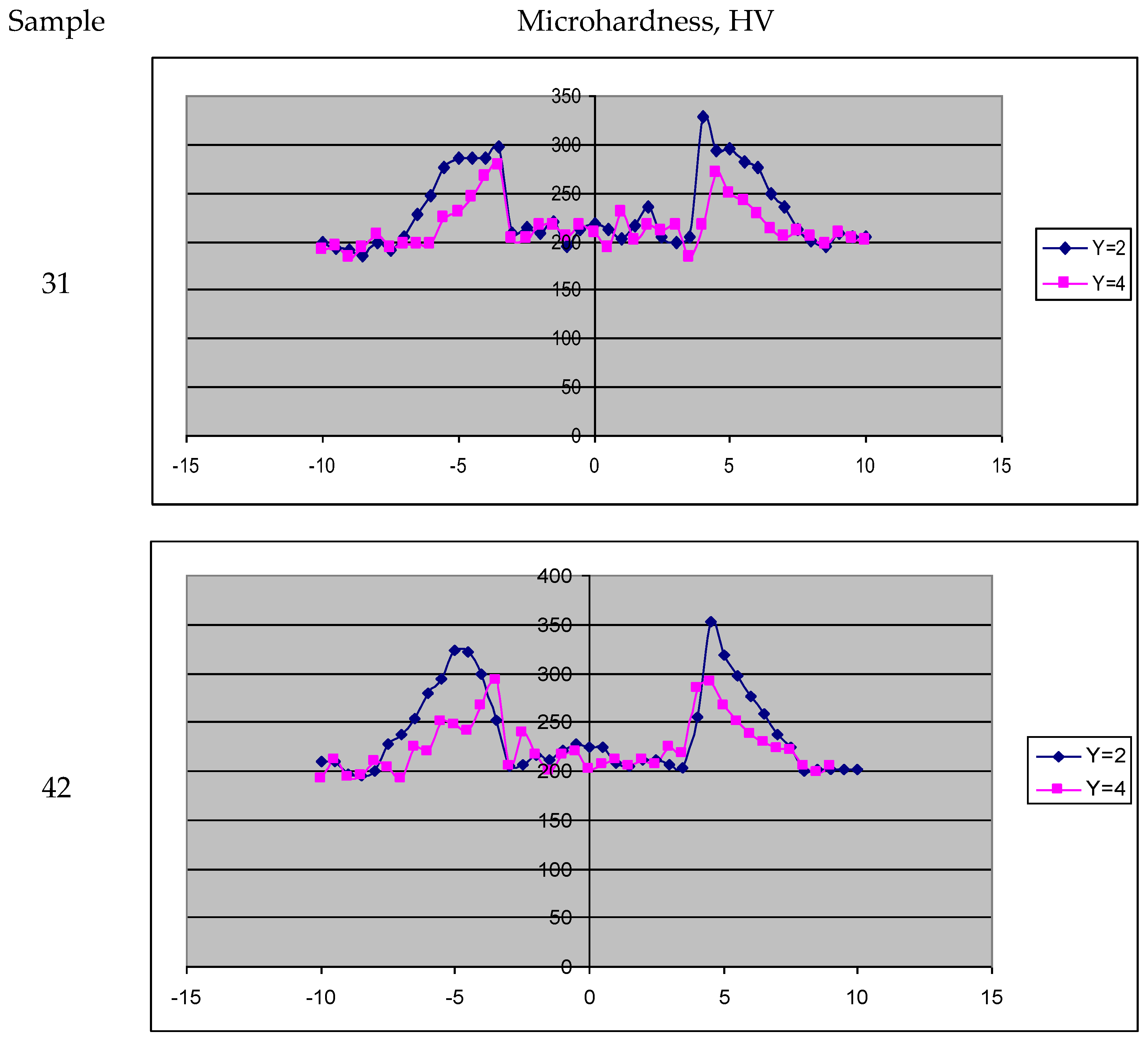
For comparison, Figure 6 shows the distribution of microhardness in the cross sections of welded joints obtained by consumable electrode welding with two- and single-jet gas shielding in the following modes: welding current Iw = 250 A, welding speed V = 25 cm/min, consumption of shielding gas Q= 28 L/min, welding arc voltage U = 26 V.
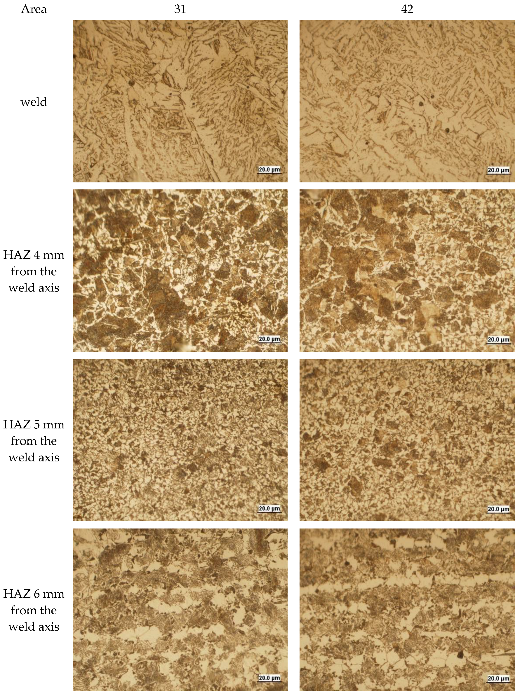
The microhardness distributions in Figure 6 are identical, but the samples that were welded using two-jet gas shielding have microhardness peaks that are 30 HV lower. This can be explained by the fact that a two-jet nozzle produces shielding gas at a significantly higher rate and distributes and equalizes heat over the product’s surface faster. The cooling rate of the HAZ increases at the time of welding and its instantaneous overheating decreases, which changes the pattern of structural phase transitions (Figure 7) and the microhardness distribution in the cross-section of welded joints made of steel 45. Additionally, the droplet size reduces and the frequency of their transfer rises during welding with two-jet gas shielding due to the active shielding gas’s dynamics. As a result, the weld pool metal and the HAZ are not overheated as much, which alters the pattern of structural phase transitions (Figure 7) and the microhardness distribution in the cross-section of the welded joints (Figure 6).
4. Conclusions
The research investigated mechanized multipass two-jet gas shielding welding of plates made of steel 45 in CO2 with a stationary arc without preheating and subsequent heat treatment. The obtained result analysis demonstrates that:
- -
- there is an asymmetric distribution of microhardness in the cross sections of welded joints relative to the axis of the weld, which indicates some difference in the structure and properties of the HAZ and the weld;
- -
- the microhardness values of the weld metal are roughly the same across the layers and vary in the range of 190–250 HV, which is the same as the microhardness of the base metal;
- -
- the peak of microhardness (300–420 HV) is located in the fusion zone of multilayer welded joints and its value decreases along the depth of slotted edges because of auto-heat treatment with upper layers;
- -
- an increase in the heat input of welding (a simultaneous increase in the welding current and voltage of the welding arc) leads to a decrease in the gradient (peak) of microhardness in the HAZ;
- -
- a simultaneous increase in the welding current and voltage of the welding arc changes the structure in the corresponding sections of the HAZ, the grains become larger and coarser, and there is an expansion of the HAZ and a shift of its sections toward the base metal;
- -
- consumable electrode arc welding with two-jet gas shielding provides faster distribution and equalization of heat on the product surface and reduces its instantaneous overheating, which improves the structural phase state of the welded joint made of steel 45 and reduces the microhardness gradient in the HAZ.
Author Contributions
Methodology, validation, formal analysis, writing original draft preparation, writing—review and editing, D.A.C.; data curation, visualization, writing original draft preparation, D.P.I. All authors have read and agreed to the published version of the manuscript.
Funding
The investigation of the grain structures was performed according to the Government research assignment for ISPMS SB RAS, project FWRW-2021-0003.
Data Availability Statement
Not applicable.
Conflicts of Interest
The authors declare no conflict of interest.
References
- Gisario, A.; Kazarian, M.; Martina, F.; Mehrpouya, M. Metal additive manufacturing in the commercial aviation industry: A review. J. Manuf. Syst. 2019, 53, 124–149. [Google Scholar] [CrossRef]
- Bao, Y.; Xue, R.; Zhou, J.; Liu, H.; Xu, Y. The Influence of Oscillation Parameters on the Formation of Overhead Welding Seams in the Narrow-Gap GMAW Process. Appl. Sci. 2023, 13, 5519. [Google Scholar] [CrossRef]
- Silva, A.P.; Węgrzyn, T.; Szymczak, T.; Szczucka-Lasota, B.; Łazarz, B. Hardox 450 Weld in Microstructural and Mechanical Approaches after Welding at Micro-Jet Cooling. Materials 2022, 15, 7118. [Google Scholar] [CrossRef] [PubMed]
- Chinakhov, D.A.; Ovcharenko, V.E. Influence of gas-dynamic conditions on the processes in the melting electrode welding area and the formation of welded joint. AIP Conf. Proc. 2021, 2351, 030079. [Google Scholar] [CrossRef]
- Liu, L.M.; Wang, Z.L.; Zhang, T.Y.; Ba, X.L. Analysis of metal transfer and weld forming characteristics in triple-wire gas indirect arc welding. Int. J. Adv. Manuf. Technol. 2022, 120, 6777–6788. [Google Scholar] [CrossRef]
- Qin, G.L. Development and application of narrow gap gas shielded welding process. Metalwork. Hot Work 2022, 9, 8–20. [Google Scholar]
- Potapevsky, A.G. Welding in Shielding Gases with a Consumable Electrode; Mashinostroenie: Moscow, Russia, 1974; 240p. [Google Scholar]
- Ley, F.H.; Campbell, S.W.; Galloway, A.M.; McPherson, N.A. Effect of shielding gas parameters on weld metal thermal properties in gas metal arc welding. Int. J. Adv. Manuf. Technol. 2015, 80, 1213–1221. [Google Scholar] [CrossRef] [Green Version]
- Valiente Bermejo, M.A.; Karlsson, L.; Svensson, L.-E.; Hurtig, K.; Rasmuson, H.; Frodigh, M.; Bengtsson, P. Effect of shielding gas on welding performance and properties of duplex and superduplex stainless steel welds. Weld. World 2014, 59, 239–249. [Google Scholar] [CrossRef]
- Wang, L.L.; Lu, F.G.; Wang, H.P.; Murphy, A.B.; Tang, X.H. Effects of shielding gas composition on arc profile and molten pool dynamics in gas metal arc welding of steels. J. Phys. D Appl. Phys. 2014, 47, 465202. [Google Scholar] [CrossRef]
- Chang, Y.H. Improve GMAW and GTAW with alternating shield gases. Weld. J. 2006, 85, 41–43. [Google Scholar]
- Soderstrom, E.J.; Mendez, P.F. Metal transfer during GMAW with thin electrodes and Ar-CO2 shielding gas mixtures. Weld. J. 2008, 87, 124–133. [Google Scholar]
- Rao, Z.H.; Hu, J.; Liao, S.M.; Tsai, H.L. Study the shielding gas effect on the metal transfer and weld pool dynamics in GMAW. In Proceedings of the ASME Summer Heat Transfer Conference 2009, San Francisco, CA, USA, 19–23 July 2009; HT2009. Volume 3, pp. 675–684. [Google Scholar]
- Rosado-Carrasco, J.G.; González-Zapatero, W.F.; García, C.J.; Gómora, C.M.; Jaramillo, D.; Ambriz, R.R. Analysis of the Low Cycle Fatigue Behavior of DP980 Steel Gas Metal Arc Welded Joints. Metals 2022, 12, 419. [Google Scholar] [CrossRef]
- Ramsey, G.M.; Galloway, A.M.; Campbell, S.W.; McPherson, N.A.; Scanlon, T.J. A computational fluid dynamic analysis of the effect of side draughts and nozzle diameter on shielding gas coverage during gas metal arc welding. J. Mater. Process. Technol. 2012, 212, 1694–1699. [Google Scholar] [CrossRef] [Green Version]
- Beyer, V.; Campbell, S.W.; Ramsey, G.M.; Galloway, A.M.; Moore, A.J.; McPherson, N.A. Systematic study of effect of cross-drafts and nozzle diameter on shield gas coverage in MIG welding. Sci. Technol. Weld. Join. 2013, 18, 652–660. [Google Scholar] [CrossRef] [Green Version]
- Hantsch, H.; Beese, E.; Timmer, K. Status of the development of an attachment nozzle for MAG welding with a dual gas flow. Weld. Cut. 2008, 7, 348–353. [Google Scholar]
- Zhernosekov, A.M.; Sidorets, V.N.; Shevchook, S.A. Combined pulsed effect of shielding gases and welding current in consumable electrode welding. Weld. Int. 2014, 28, 962–965. [Google Scholar] [CrossRef]
- Mvola, B.; Kah, P. Effects of shielding gas control: Welded joint properties in GMAW process optimization. Int. J. Adv. Manuf. Technol. 2017, 88, 2369–2387. [Google Scholar] [CrossRef]
- Kang, B.Y.; Prasad, Y.K.D.V.; Kang, M.J.; Kim, H.J.; Kim, I.S. Characteristics of alternate supply of shielding gases in aluminum GMA welding. J. Mater. Process. Technol. 2009, 209, 4716–4721. [Google Scholar] [CrossRef]
- Rao, Z.H.; Hu, J.; Liao, S.M.; Tsai, H.L. Modeling of the transport phenomena in GMAW using argon-helium mixtures. P. II—The metal. Int. J. Heat Mass Transf. 2010, 53, 22–32. [Google Scholar] [CrossRef]
- Campbell, S.W.; Galloway, A.M.; McPherson, N.A.; Gillies, A. Evaluation of gas metal arc welding with alternating shielding gases for use on AA6082T6. Proceedings of the Institution of Mechanical Engineers. Proc. B J. Eng. Manuf. 2012, 226, 992–1000. [Google Scholar] [CrossRef] [Green Version]
- Li, Z.H.; Xin, J.W.; Xiao, X.; Wang, H.; Hua, X.M.; Wu, D.S. The arc physical characteristics and molten pool dynamic behaviors in conduction plasma arc welding. Acta Metall. Sin. 2021, 57, 693–702. [Google Scholar]
- Yoji, W.; Satohiro, I.; Hiroshi, T.; Tomiko, Y.; Kazumasa, N. Computational fluid dynamics analysis of shielding gas behaviour in tungsten inert gas welding of titanium plate. Weld. Int. 2015, 29, 18–26. [Google Scholar] [CrossRef]
- Chinakhov, D.A.; Grigorieva, E.G.; Mayorova, E.I. Influence of Gas Shielding Method in Welding with Consumable Electrode on Heat Distribution in a Welded Product. Solid State Phenom. 2017, 265, 463–469. [Google Scholar] [CrossRef]
- Zaruba, I.I.; Kasatkin, B.S.; Kakhovsky, N.I.; Potapevsky, A.G. Welding in Carbon Dioxide; Gostekhizdat of the Ukrainian SSR: Kyiv, Ukraine, 1960; 224p. [Google Scholar]
- Ardentov, V.V.; Fedorenko, G.A. About jet protection in gas-electric welding. Weld. Prod. 1973, 1, 3–5. [Google Scholar]
- Chinakhov, D.A.; Grigorieva, E.G.; Mayorova, E.I.; Kartsev, D.S. The influence of shielding gas flow rate on the transfer frequency of electrode metals drops. IOP Conf. Ser. Mater. Sci. Eng. 2016, 142, 012005. [Google Scholar] [CrossRef]
- Dragunov, Y.G.; Zubchenko, A.S.; Kashirsky, Y.V.; Degtyarev, A.F.; Zharov, V.V.; Koloskov, M.M.; Orlov, A.S.; Skorobogatykh, V.N. Marker of Steels and Alloys; Innovative Engineering: Moscow, Russia, 2021; 1216p. [Google Scholar]
Figure 1.
Scheme of shielding gas outflow from the welding nozzle: (a) traditional single-jet gas shielding; (b) two-jet gas shielding: 1—nozzle; 2—electrode wire; 3—welding candle; 4—workpiece.
Figure 1.
Scheme of shielding gas outflow from the welding nozzle: (a) traditional single-jet gas shielding; (b) two-jet gas shielding: 1—nozzle; 2—electrode wire; 3—welding candle; 4—workpiece.

Figure 2.
Images of temperature fields obtained by a thermal imager (a,b), temperature fields after processing: (c) immediately after welding (heating) t = 60 s; (d) 60 s after welding (cooling) t = 120 s. Investigation area of the temperature fields on the surface of the plates to be welded (Width and length, mm).

Figure 3.
Thermal cycles at points Y = 0 cm (1), Y = 0.5 cm (2), Y = 1.4 cm (3) from the weld axis when welding in CO2: (a) for two-jet gas shielding, (b) for single-jet gas shielding. T, C is the temperature in degrees Celsius; t, s is the time of temperature measurement in seconds.
Figure 3.
Thermal cycles at points Y = 0 cm (1), Y = 0.5 cm (2), Y = 1.4 cm (3) from the weld axis when welding in CO2: (a) for two-jet gas shielding, (b) for single-jet gas shielding. T, C is the temperature in degrees Celsius; t, s is the time of temperature measurement in seconds.

Figure 4.
The microhardness distribution in the cross sections of the welded joints depending on the controlled parameters of the welding mode (Q, Iw, U) for two-jet gas shielding. The abscissa axis shows the weld width in mm, and the ordinate axis shows the microhardness, HV.
Figure 4.
The microhardness distribution in the cross sections of the welded joints depending on the controlled parameters of the welding mode (Q, Iw, U) for two-jet gas shielding. The abscissa axis shows the weld width in mm, and the ordinate axis shows the microhardness, HV.

Figure 5.
Microstructure in the zones of welded joints obtained by welding modes 1 and 8 of the planning matrix of the full factorial experiment, along the line Y = 4 mm.
Figure 5.
Microstructure in the zones of welded joints obtained by welding modes 1 and 8 of the planning matrix of the full factorial experiment, along the line Y = 4 mm.

Figure 6.
The microhardness distribution in cross-sections of welded joints obtained by consumable electrode welding with two-jet gas shielding (31) and single-jet gas shielding (42). The abscissa axis shows the weld width in mm, and the ordinate axis shows the microhardness, HV.
Figure 6.
The microhardness distribution in cross-sections of welded joints obtained by consumable electrode welding with two-jet gas shielding (31) and single-jet gas shielding (42). The abscissa axis shows the weld width in mm, and the ordinate axis shows the microhardness, HV.

Figure 7.
Microstructure in the zones of welded joints obtained by consumable electrode welding with two-jet gas shielding (31) and single-jet gas shielding (42), along the line Y = 4 mm.
Figure 7.
Microstructure in the zones of welded joints obtained by consumable electrode welding with two-jet gas shielding (31) and single-jet gas shielding (42), along the line Y = 4 mm.


Table 1.
Chemical Composition of Steel 45 and Welding Wire Sv-08G2S.
| Material | Mass Fraction of Elements, % | ||||||
|---|---|---|---|---|---|---|---|
| C | Mn | Si | S | P | Cr | Ni | |
| Steel Grade Guide [29] | |||||||
| Steel 45 Ghost 1050–88 | 0.42–0.5 | 0.5–0.8 | 0.17–0.37 | ≤0.04 | ≤0.035 | ≤0.25 | ≤0.3 |
| Sv-08G2S Ghost 2246–70 | 0.05–0.11 | 1.8–2.1 | 0.7–0.95 | ≤0.025 | ≤0.03 | ≤0.2 | ≤0.25 |
| Averaged Research Results | |||||||
| Steel 45 | 0.43 | 0.62 | 0.31 | 0.013 | 0.016 | 0.15 | 0.03 |
| Sv-08G2S | 0.07 | 1.80 | 0.78 | 0.006 | 0.020 | 0.06 | 0.07 |
Table 2.
Full factorial experiment planning matrix.
| Name of Controlled Parameter | № Test | |||||||
|---|---|---|---|---|---|---|---|---|
| 1 | 2 | 3 | 4 | 5 | 6 | 7 | 8 | |
| 1. Shielding gas consumption Q, L/min (±0.5) | 25 | 30 | 25 | 30 | 25 | 30 | 25 | 30 |
| 2. Welding current Iw, (±2) | 170 | 170 | 200 | 200 | 170 | 170 | 200 | 200 |
| 3. Arc voltage U, V (±0.5) | 26 | 26 | 26 | 26 | 29 | 29 | 29 | 29 |
Table 3.
The chemical composition of the weld metal of the 45 multilayer welded steel samples.
| Sample | C | Si | Mn |
|---|---|---|---|
| Mass Fraction of Elements, % | |||
| 1 | 0.12 | 0.55 | 1.35 |
| 2 | 0.13 | 0.53 | 1.28 |
| 3 | 0.1 | 0.58 | 1.4 |
| 4 | 0.1 | 0.54 | 1.31 |
| 5 | 0.11 | 0.45 | 1.09 |
| 6 | 0.12 | 0.39 | 1.02 |
| 7 | 0.11 | 0.44 | 1.11 |
| 8 | 0.1 | 0.33 | 1.05 |
Disclaimer/Publisher’s Note: The statements, opinions and data contained in all publications are solely those of the individual author(s) and contributor(s) and not of MDPI and/or the editor(s). MDPI and/or the editor(s) disclaim responsibility for any injury to people or property resulting from any ideas, methods, instructions or products referred to in the content. |
© 2023 by the authors. Licensee MDPI, Basel, Switzerland. This article is an open access article distributed under the terms and conditions of the Creative Commons Attribution (CC BY) license (https://creativecommons.org/licenses/by/4.0/).
Share and Cite
MDPI and ACS Style
Chinakhov, D.A.; Il’yashchenko, D.P. The Influence of Two-Jet Gas Shielding Parameters on the Structure and Microhardness of Steel 45 Joints during Consumable Electrode Welding. Metals 2023, 13, 1136. https://doi.org/10.3390/met13061136
AMA Style
Chinakhov DA, Il’yashchenko DP. The Influence of Two-Jet Gas Shielding Parameters on the Structure and Microhardness of Steel 45 Joints during Consumable Electrode Welding. Metals. 2023; 13(6):1136. https://doi.org/10.3390/met13061136
Chicago/Turabian StyleChinakhov, Dmitry A., and Dmitry Pavlovich Il’yashchenko. 2023. "The Influence of Two-Jet Gas Shielding Parameters on the Structure and Microhardness of Steel 45 Joints during Consumable Electrode Welding" Metals 13, no. 6: 1136. https://doi.org/10.3390/met13061136
Note that from the first issue of 2016, this journal uses article numbers instead of page numbers. See further details here.