
Fatigue Behavior and Fracture Features of Ti-15Mo Alloy in β-, (α + β)-, and Ultrafine-Grained Two-Phase States


Laboratory of Multifunctional Materials, Ufa University of Science and Technology, 450076 Ufa, Russia
*
Author to whom correspondence should be addressed.
Metals 2023, 13(3), 580; https://doi.org/10.3390/met13030580
Submission received: 31 January 2023
/
Revised: 9 March 2023
/
Accepted: 10 March 2023
/
Published: 13 March 2023
(This article belongs to the Special Issue Fatigue Behavior and Crack Mechanism of Metals and Alloys)
Abstract
:The influence of the ultrafine-grained structure formed by equal-channel angular pressing via the “Conform” scheme on the fatigue behavior of metastable β-alloy Ti-15Mo has been studied. It is shown that the alloy with a two-phase ultrafine-grained structure achieved the best mechanical properties and enhanced fatigue endurance limit (up to 710 MPa on the basis of 107 cycles) due to the total contribution of grain boundary, dislocation, and phase strengthening mechanisms. A fractographic analysis of the fracture surface of samples after fatigue tests showed the features of fatigue crack propagation depending on the type of alloy microstructure. The general and distinctive features of fatigue failure of alloy samples in the initial coarse-grained (α + β)-, single-phase coarse-grained β-, and ultrafine-grained (α + β)-states are revealed. In all of the samples, a fatigue crack nucleated on the surface and propagated downward, i.e., perpendicular to the direction of the applied pressures. It is shown that fracture surfaces of the ultrafine-grained samples had a high roughness and were characterized by the presence of a large number of secondary cracks, as compared to the coarse-grained analogues.
1. Introduction
Titanium and its alloys have been considered among the best materials for artificial implants due to their excellent biocompatibility, good corrosion resistance, and high specific strength. These materials are widely used in the areas of load-bearing implants such as hip joints, knee joints, and dental implants [1,2,3,4,5,6]. Among them, the most popular alloy for implants is still (α + β)-titanium alloy Ti-6Al-4V, which exhibits high strength and fatigue endurance limit [1,7]. However, recent studies have shown that the alloy has a long-term histotoxic effect on the human body, which is associated with the release of Al and V [8,9]. Additionally, the material has a higher elastic modulus (>110 GPa) than human cortical bones (~30 GPa), which offers significant stress-shielding. This leads to implant loosening, premature failure, and the need for revision surgery. [1,7]. In this regard, at present, much attention is being paid to the development of metastable β-titanium alloys which do not contain elements that have a negative effect on the human body. Metastable β-titanium alloys have the ability to change mechanical properties and elastic modulus depending on the structure and phase composition, which is controlled by the applied thermal and deformation treatments [10,11,12,13,14,15,16]. The properties of β-alloys can also be controlled by alloying and surface modification [8,10].
Ti-15Mo is one such metastable β-titanium alloy. The addition of non-toxic molybdenum increases the alloy’s corrosion resistance [17]. The alloy in the single-phase β-state has high ductility (>30%) and low elastic modulus (78 GPa) but ranks significantly below (α + β)-titanium alloys in terms of strength [18]. Conventional processing methods, including cold deformation (rolling) and aging, make it possible to achieve tensile strength values of more than 1500 MPa; however, the ductility is reduced to 5%. The precipitation of second phases can cause the elastic modulus to increase to values exceeding 120 GPa [19,20]. At the same time, high-cycle fatigue life requires a combination of high strength and satisfactory ductility. It is known that a complex of such properties can be achieved by severe plastic deformation (SPD) in combination with low-temperature annealing, due to the formation of ultrafine-grained (UFG) structures [21,22,23].
It was shown in [24,25,26,27] that SPD significantly affects the mechanical properties and kinetics of the precipitation of secondary phases in metastable β-titanium alloys. In particular, SPD improves the strength characteristics due to grain refinement and introduction of a large number of crystal lattice defects into the material, which also contributes to a more uniform decomposition of the β-phase during subsequent aging. In [28], the UFG structure formed in the Ti-5Al-5V-5Mo-1Cr-1Fe metastable β-titanium alloy, with the help of radial shear rolling and subsequent aging, made it possible to increase high-cycle fatigue (HCF) by more than 30% on the basis of 107 cycles, compared to coarse-grained (CG) counterpart materials. In addition, very high cycle fatigue results have been shown. In [29], the authors demonstrated that the formation of a nanosubgrain structure in the Ti-18Zr-14Nb metastable alloy by radial shear rolling and thermomechanical treatment made it possible to achieve a favorable combination of strength and elastic modulus with stable fatigue properties. In [30], it was shown that the formation of the UFG Ti-45Nb alloy samples by multidirectional forging (abc–forging) and further rolling resulted in an increased fatigue limit in the gigacycle regime, i.e., up to 295 MPa, which is 1.5 times more compared to the CG sample (fatigue limit: 195 MPa).
At the same time, it is known that the UFG structure not only has a favorable effect on high-cycle fatigue due to enhanced strength but also significantly impacts the fatigue behavior, including the kinetics of fatigue crack growth and failure mechanisms [31,32,33,34,35]. In particular, the authors of [32] note that in the high-cycle fatigue area, strength enhancement in a material increases its resistance to crack initiation, and that an increase in the length of the grain boundaries slows the rate of crack propagation, intensifying the tortuosity of its trajectory. In contrast, in the low-cycle fatigue area, the limited mobility of the dislocations in ultrafine grains can lead to the suppression of the effect of crack tip blunting, resulting in faster propagation of sharp cracks in the UFG state.
A comparison of the fatigue behavior of single-phase and multi-phase alloys [31] showed that, along with the grain size, important structural factors that impact the fatigue properties and fracture characteristics are as follows: size, morphology and distribution of second phases, density and type of dislocation motion, and the ability of the material to undergo cyclic strengthening/softening. It is also shown that the structure impacts the crack propagation mechanism. Thus, in [34], the main fatigue crack developed according to the transcrystalline mechanism in the CG and UFG states of Ti-6Al-4V alloy, while in CG samples, secondary microcracks developed in the phase boundaries or in the β-phase, and in UFG samples, those developed perpendicular to the main crack, which had a favorable effect on the fatigue life.
However, the vast majority of studies on the features of the fatigue failure of UFG titanium alloys were carried out on pure α-titanium or (α + β) alloys [31,33,34]. The influence of the UFG structure on the fatigue life and the features of the fatigue failure of metastable β-titanium alloys are presented in separate studies [28,29,30].
In the present work, we studied, for the first time, the features of the fatigue failure of medical (ASTM F2066) Ti-15Mo alloy with a UFG structure, processed by equal-channel angular pressing “Conform” (ECAP-C) in combination with drawing in comparison with its coarse-grained analogue. The differences in the fatigue behavior of the material in the single-phase β and two-phase (α + β) states will also be revealed. Thus, the aim of this work is to study the effect of the microstructure and phase composition parameters on the fatigue behavior and fracture features of Ti-15Mo alloy. This work is the continuation of [36], which focused on the effect of ECAP-C based on the microstructure and mechanical and fatigue properties of Ti-15Mo alloy.
2. Materials and Methods
The research material was Ø 15 mm rods of Ti-15Mo metastable β-titanium alloy with a two-phase (α + β) structure, manufactured by Dynamet Carpenter, Richmond, VA, USA (Table 1).
To produce a single-phase CG β-state, the initial rods were subjected to water quenching (WQ) from a temperature above β-transus 810 °C (the β-transus temperature of Ti-15Mo is 750 °C [37]); the heating time was 20 min.
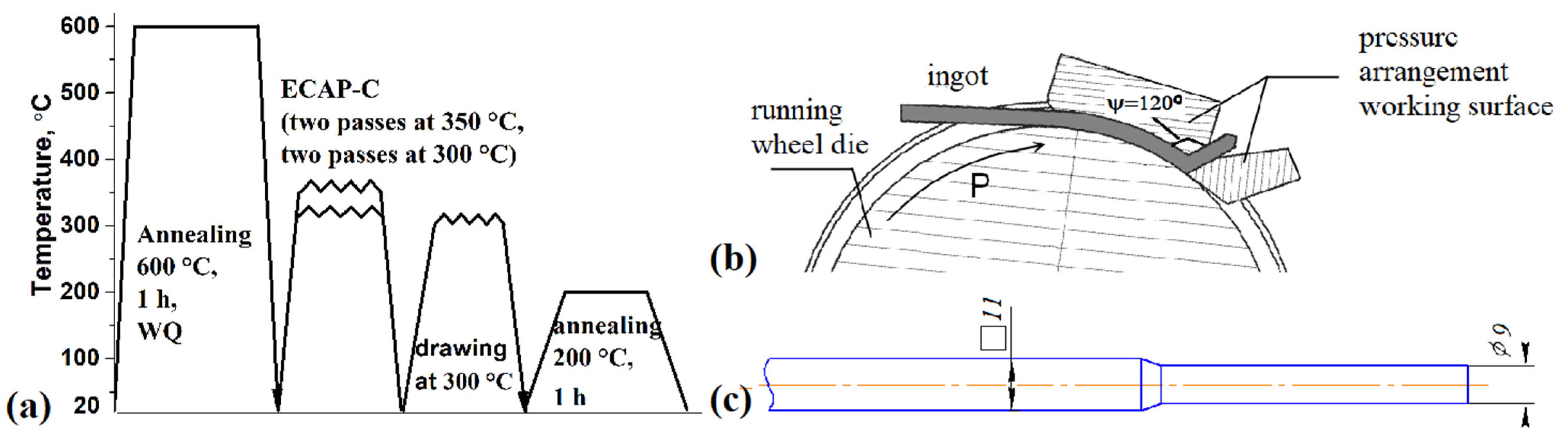
The (α + β)- UFG structure was obtained using combined thermomechanical treatment [36], a schematic of which is shown in Figure 1a. To improve the alloy ductility, prior to deformation, the initial rods were subjected to annealing at a temperature of 600 °C ((α + β)-region [37]) with subsequent cooling in water; the dwell time in the furnace was 1 h. The ECAP-C method was used to form the UFG structure [38] (Figure 1b). Two passes were carried out at a temperature of 350 °C, and two more at a temperature of 300 °C. The ECAP-C 600 facility (UUST, Ufa, Russia) was used, having a square-section channel with a side size of 11 mm and an intersection angle of the working parts of the die-set of 120°. The rods after ECAP-C had a square section of 11 × 11 mm. The strain was e = 2.8 (1):
where N is the number of passes, and ψ is the intersection angle of the die-set channels.
Further, drawing at 300 °C was used for additional hardening and to give the rod a round section. Prior to drawing, the billet’s front part, required for use with rolls, was machined to Ø 9.0 mm on a turning lathe (Figure 1c). Then, the billet passed through a series of dies with a consecutive decrease in diameter. The reduction ratio during the drawing process was 60%. The final diameter of the rods was 6 mm. Low-temperature annealing was performed at 200 °C for 1 h to relieve internal stresses [36].
A fractographic analysis of the fracture surfaces of the samples was performed using a JSM-6390 scanning electron microscope (SEM) (JEOL, Tokyo, Japan). A microstructural study and energy dispersive spectroscopy (EDS) of the alloy in the initial (α + β)-CG state were conducted using a Tescan Mira SEM (Tescan, Brno, Czech Republic) equipped with a 30 Xplore Oxford EDS attachment (Oxford, UK), in back-scattered electrons mode. The microstructure of the quenched alloy was studied using an Olympus GX53 optical microscope (OM) (Olympus Corp., Tokyo, Japan). To determine the structure of the samples, etching was carried out in an aqueous solution with the addition of hydrofluoric and nitric acids. The UFG structure was examined using a JEM-2100 transmission electron microscope (TEM) (JEOL, Tokyo, Japan) at an accelerating voltage of 200 kV. The samples for TEM analysis were polished on a Tenupol-5 double jet polisher (Struers, Ballerupcity, Denmark) at T = −30 °C in an electrolyte based on methanol, butanol, and perchloric acid at a voltage of 25 V. The size of the structural elements was determined by the linear intercept method, analyzing at least 10 images of the structure. A phase analysis of the alloy was carried out on an X-Ray Ultima IV diffractometer (Rigaku, Tokyo, Japan) by CuKα irradiation (40 kV and 30 mA; the slit size was 2 × 10 mm). The wavelength λKα1 = 1.54060 Å was used for calculations. A general view of the X-ray patterns was taken with a scanning step of 0.02° and an exposure time at each point equal to 3 s. The phase composition of the alloy was determined via the Rietveld refinement method using Material Analysis Using Diffraction (MAUD) 1.993 for Windows [39]. Rietveld reference-free full-profile analysis was conducted with a procedure for minimizing the deviation between the experimental and calculated X-ray.
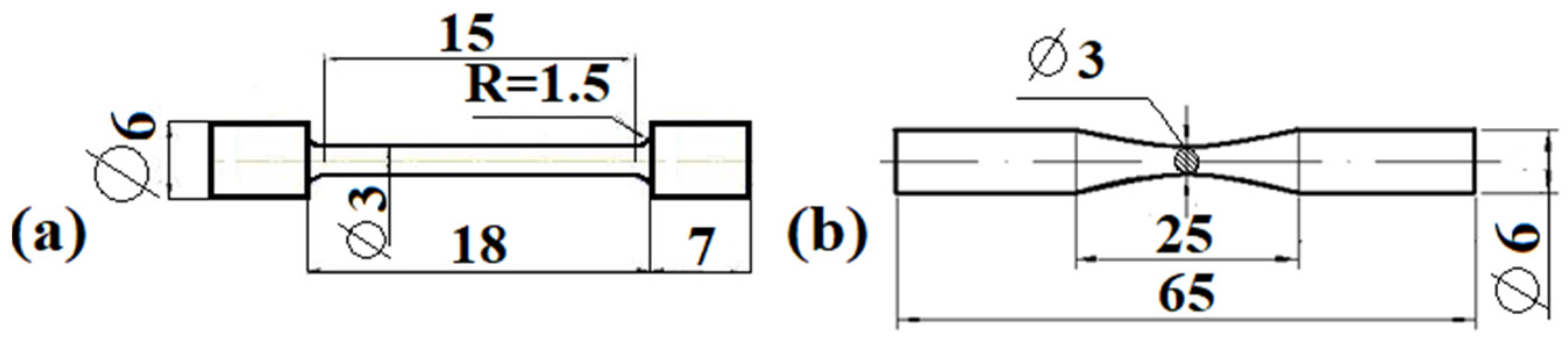
Tensile testing was carried out on an Instron 5982 machine (Instron Engineering Corporation, Buckinghamshire, UK) at 20 °C, in accordance with ISO 6892-84. The strain rate was 10−3 s−1. Cylindrical samples for tests with a gauge diameter of 3 mm were cut from the central portion of the rod in the longitudinal direction. A schematic of the samples is shown in Figure 2a. At least three samples were tested in each state.
Fatigue tests were carried out at 20 °C on an Instron 8801 machine (Instron Engineering Corporation, Buckinghamshire, UK) in tensile-compression conditions with a symmetrical loading cycle R = −1 with a frequency f = 30 Hz and a baseline of 107 cycles. Smooth samples cut from the central portion of the rod in the longitudinal direction were used; see Figure 2b. At least 15 samples were tested in each state. In a stress range of 0.95–1.05 of the probable endurance limit, at least three samples were tested.
The average step of fatigue striations was calculated from the SEM images of the specimen fractures. The length of a line perpendicular to the group of striations was measured, and the resulting value was divided by the number of striations in this group. A minimum of five images was evaluated for each fracture zone.
3. Results and Discussion
3.1. Investigation of Microstructure and Mechanical Properties
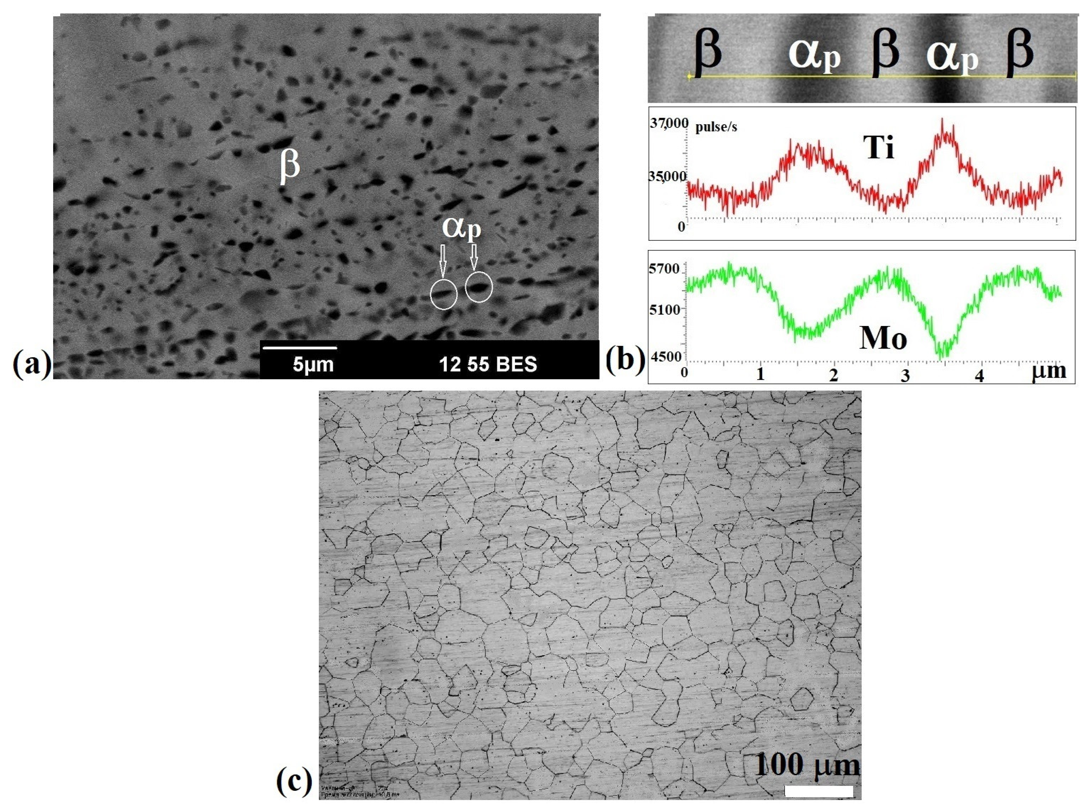
Ti-15Mo alloy in the initial state had a coarse-grained structure consisting of particles of a primary αp-phase (dark regions, Figure 3a) with an average size of 1.2 ± 0.3 µm and oriented along the rolling direction (the method applied to produce the initial rods) and β-grains with an average size of 2.5 ± 0.5 µm (bright regions, Figure 3a). Since the boundaries of the β-grains were not clearly visualized, the distance between the αp-particles was regarded as the average β-grain size, taking into account the fact that the primary αp-phase precipitates predominantly at the boundaries of the β-grains [12,37]. The volume fraction of the primary αp-phase determined by X-ray analysis was 23 ± 2%. Figure 3b shows the results of our EDS analysis. It is visible that the α-particles (dark regions) are depleted of the β-stabilizer—Mo. The Mo content in the α-phase was 12.2 ± 0.6% and 17 ± 0.6% in the β-phase. Alloy quenching led to the formation of a single-phase β-structure with bimodal grain size distribution. The maximum number of grains had an average size of 10 ± 2 and 40 ± 2 μm (Figure 3c).
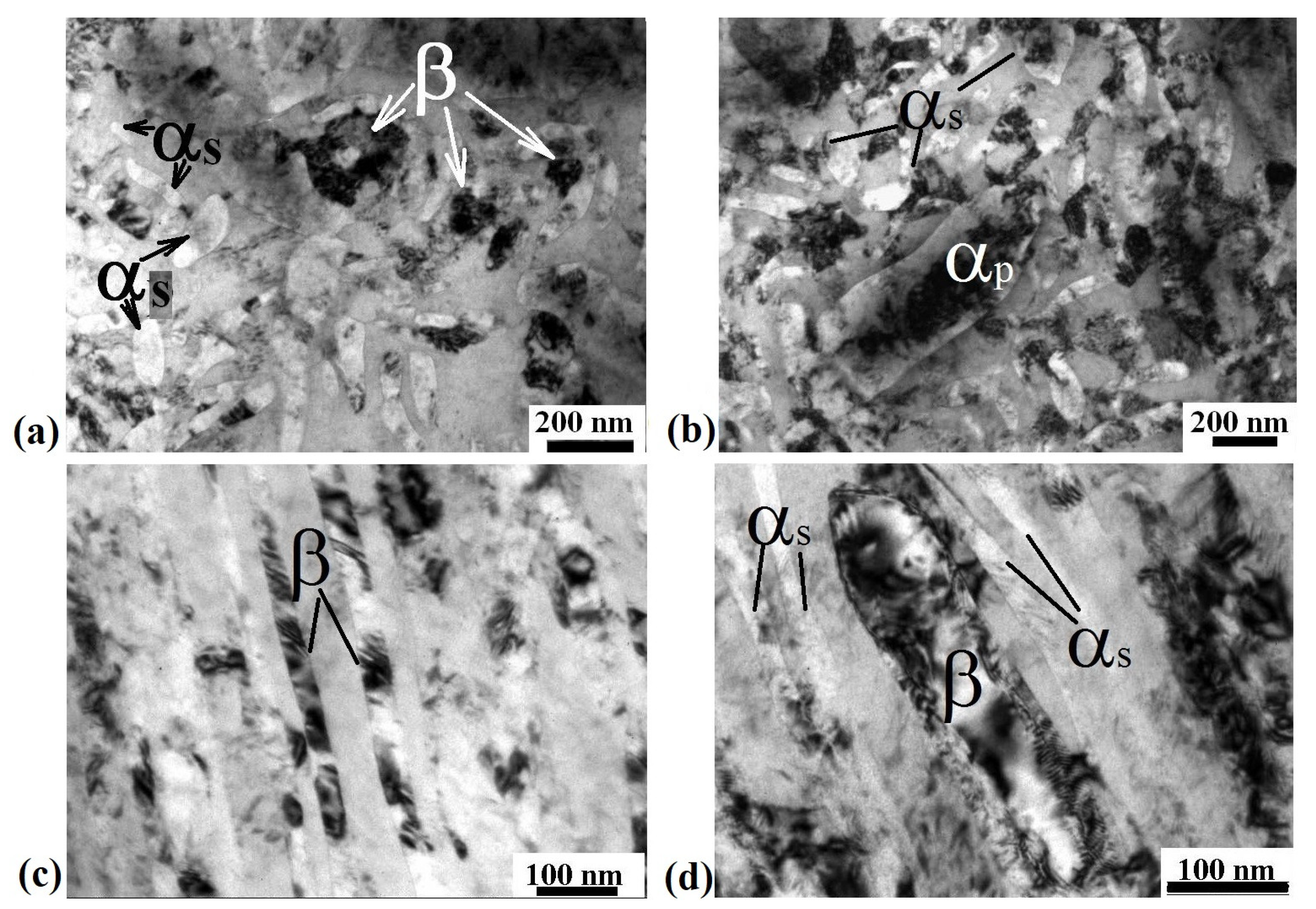
The combined thermomechanical treatment led to the refinement and fragmentation of both β-grains and αp-particles and to the formation of a sharp texture, which is typical of metals and alloys processed by drawing. Equiaxed β-grains with an average size of 150 ± 20 nm (Figure 4a), as well as particles of a primary αp-phase of globular morphology with an average size of 480 ± 30 nm and with a developed substructure inside, were observed in the cross section (Figure 4b). Elongated β-phase grains that were 35 ± 5 nm wide and oriented along the drawing direction, as well as recrystallized β-grains resulting from dynamic recrystallization and subjected to additional deformation with an average size of 100 ± 10 nm (Figure 4c,d), were found in the longitudinal section. In addition, the alloy contained particles of a secondary αs-phase of acicular morphology, 30 ± 5 nm in width, which precipitated during incomplete quenching of the alloy before deformation (Figure 4d). The volume fraction of the α-phase, determined by X-ray analysis, was 37%. A detailed description of the UFG microstructure after thermomechanical treatment is given in [36].
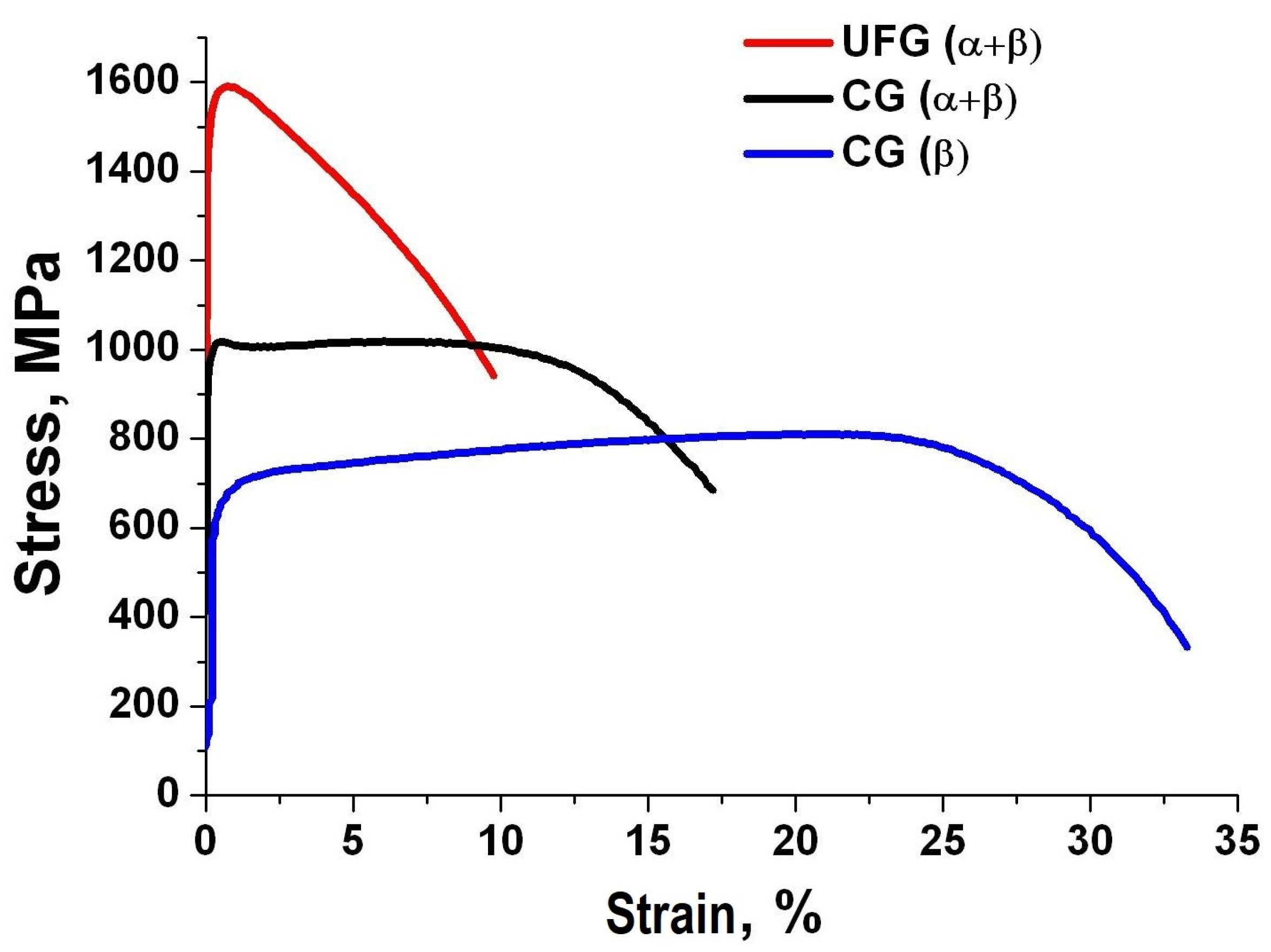
Figure 5 shows the results of mechanical tensile tests of the alloy in three structure and phase states: initial (α + β)-CG, β-CG obtained by solid solution treatment from 810 °C, and (α + β)-UFG obtained by thermomechanical treatment including ECAP-C and drawing. Depending on the type of microstructure, the samples had different mechanical properties. The alloy in the single-phase β-state with an average grain size of more than 10 µm had the lowest strength (800 ± 30 MPa) and a high ductility (35 ± 1%). In the two-phase (α + β) CG state, which was characterized by a smaller size of β-grains (2.5 μm), the strength increased to 1020 ± 30 MPa at a ductility of 17 ± 1%. The highest strength of 1590 ± 10 MPa with a ductility of 10 ± 1% was achieved in the samples subjected to SPD due to extreme refinement of β-grains to 0.15 µm, in accordance with the known Hall-Petch relation [40]. The phase mechanism of hardening contributes to the ultimate tensile strength of (α + β)-CG alloy due to the precipitation of globular particles of the primary αp-phase (23%) (Figure 3a) and, consequently, the appearance of additional interphase boundaries, which are high-angle and represent effective barriers to dislocation motion [12]. The precipitation of highly dispersed particles of the secondary αs-phase in the UFG state during TMT (the volume fraction increased to 37%) also contributes to hardening, compared to the CG state (Figure 4). Incoherent α-phase particles have an hcp crystal lattice which is characterized by a smaller number of dislocation slip systems compared to a β-matrix with a bcc lattice [12]. The motion of dislocations in them is hindered, and they bend according to the Orowan mechanism [41].
Figure 6 shows the Wöhler fatigue curves (S-N) of the alloy in the CG and UFG states, obtained during tests under the tensile-compression conditions, with a symmetrical load cycle frequency of 30 Hz. In the CG β- and UFG (α + β)-states, a knee of the S-N curve was observed during the transition from the low-cycle fatigue area to the high-cycle one. Moreover, in the UFG state, the knee was at the end of the low-cycle fatigue area and almost immediately reached the fatigue endurance limit, which is typical of high-strength materials [42]. One can see that the Wöhler curve of the UFG samples lies much higher than those of the CG samples. The UFG structure formation led to the enhancement of the cyclic properties, both in the low-cycle and high-cycle fatigue areas. It is known that the fatigue endurance limit of materials (σf) is directly dependent on the ultimate tensile strength (σuts) [35]. The greatest contribution to the increase of the mechanical properties of UFG materials is made by grain-boundary and dislocation strengthening [33]. As a first approximation, the Hall-Petch relation (2) is valid for the fatigue endurance limit, as well as for the tensile strength [33,35]. Therefore, the strength of metals increases with a decrease in grain size:
where σf0 and k are the material constants, and d is the grain size.
σf = σf0 + kd−1/2
Our tests showed that the lowest values of the fatigue endurance limit (410 ± 10 MPa) were in the quenched samples of the single-phase β-CG alloy, which had the lowest strength (Figure 5 and Figure 6). Accordingly, the two-phase (α + β)- CG had a fatigue endurance limit of 500 ± 10 MPa. The UFG two-phase (α + β)-alloy with the highest strength demonstrated the best results in terms of resistance to fatigue failure (710 ± 10 MPa).
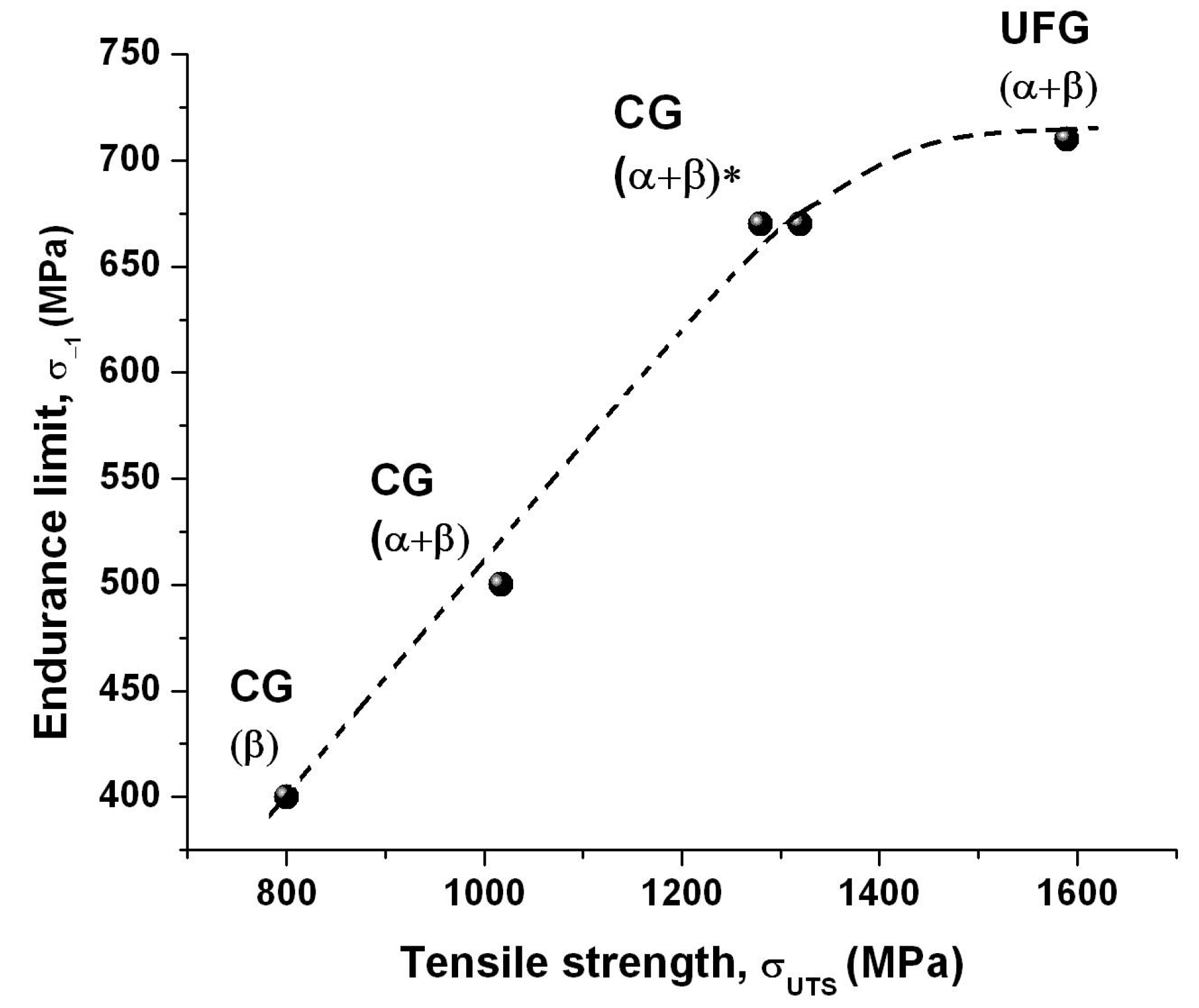
Thus, the formation of a two-phase UFG structure in Ti-15Mo alloy using severe plastic deformation leads to a significant—almost 1.5 times—increase in the fatigue endurance limit, compared to the coarse-grained state. A similar effect was demonstrated for many light UFG metals and alloys processed by SPD [31,32,33,34,35]. Table 2 lists the values of ultimate tensile strength (σuts), fatigue endurance limit (σ−1), and the ratio of fatigue strength to tensile strength (σ−1/σuts) for coarse-grained (CG) and UFG alloys Ti-15Mo, Ti Grade4 [33], and Ti-6Al-4V ELI [43]. Table 2 shows that the values of the fatigue endurance limit of Ti-15Mo alloy (710 MPa), due to the formation of a UFG structure using ECAP-C and drawing, are comparable with the values of the fatigue endurance limit (α + β) of UFG Ti-6Al-4V alloy (690 MPa). In this case, the ratio σ−1/σuts for Ti-15Mo alloy in the initial (α + β) CG state is 0.49, in β CG it is 0.51, and in the UFG state it is 0.45; this behavior is also typical of other titanium alloys [31,33,34] (Table 2) when the ultimate tensile strength enhancement due to UFG structure formation by SPD methods is higher than the increase in the fatigue endurance limit. Figure 7 clearly demonstrates this for Ti-15Mo alloy.
3.2. Fractographic Analysis of Fracture Surface
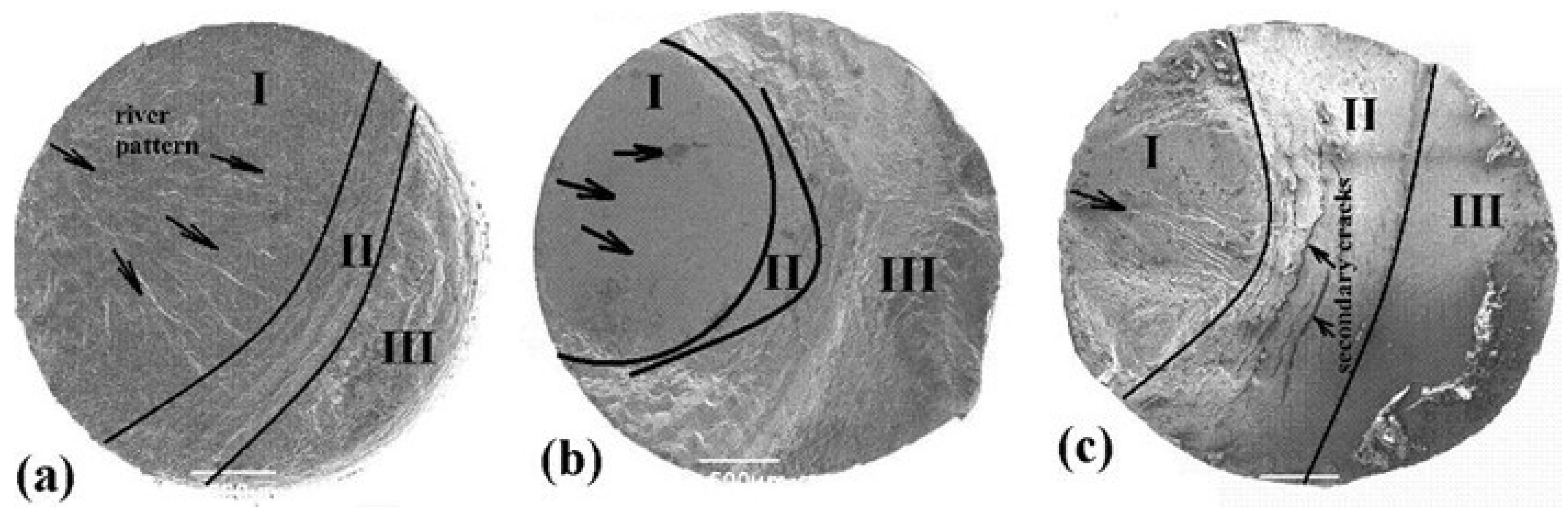
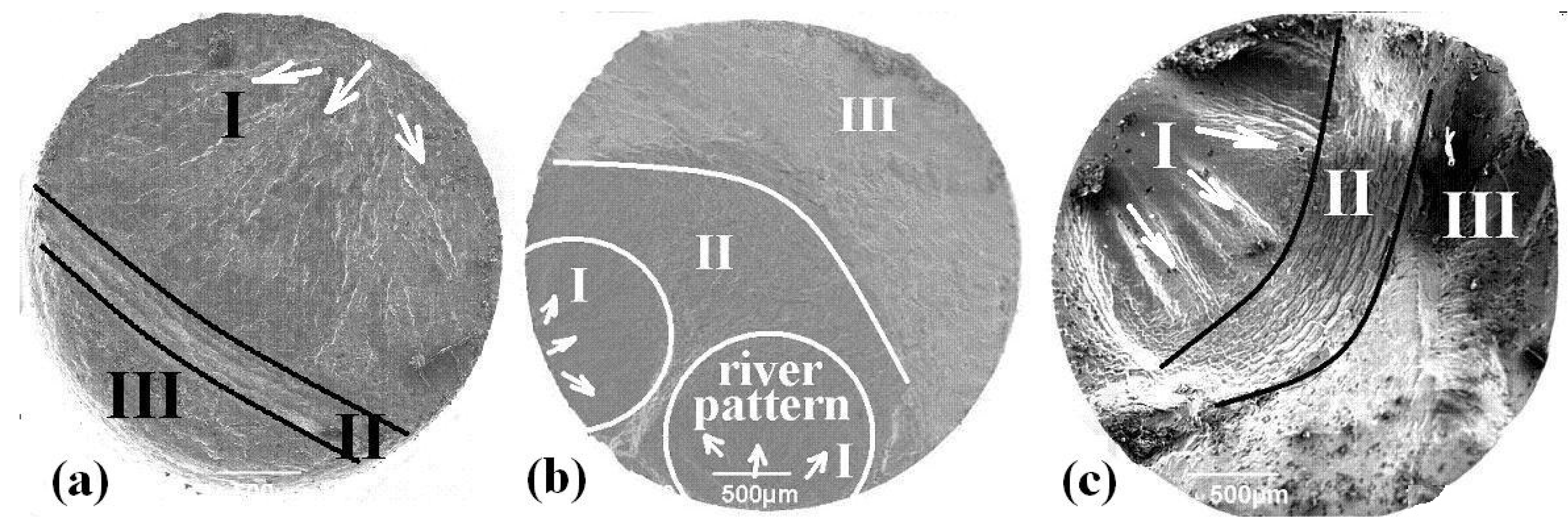
A comparative analysis was carried out to study the features of fatigue fractures of the alloy in the initial (α + β)-CG, single-phase β-CG and (α + β)-UFG states. Samples with a fatigue life of N < 104 (samples No. 1, 2, 3, marked with a circle, Figure 6) and samples that failed in the high-cycle fatigue area with a durability of N ≈ 3 × 10⁶ (samples No. 4, 5, 6, Figure 6) were used for the analysis. Due to the fact that the UFG specimens were tested at stress amplitudes much higher than those applied to the CG specimens, the fractures of the specimens that withstood a similar number of cycles before failure were compared (Figure 8, Figure 9, Figure 10 and Figure 11). Three typical zones can be distinguished on the fracture surface of the specimens: I—the region of initiation and stable growth of a crack; II—the region of accelerated crack growth; and III—the region of overload.
3.2.1. Fractographic Analysis of Fractures of Samples with Fatigue Life N < 104
Figure 8 shows a general view of the fracture surfaces of the samples (No. 1, 2, 3, Figure 6) that fractured in the low-cycle fatigue region on the Wöhler curve. β-CG has the largest area of fatigue fracture (Figure 8a). In (α + β)-CG, the fatigue fracture zone was smaller than the static rupture zone, and the zone of accelerated growth of a fatigue crack was practically absent (Figure 8b). In the UFG sample, the fatigue fracture zone occupied almost a half of the fracture surface (Figure 8c). Large secondary cracks perpendicular to the main one could be seen in the center of the sample.
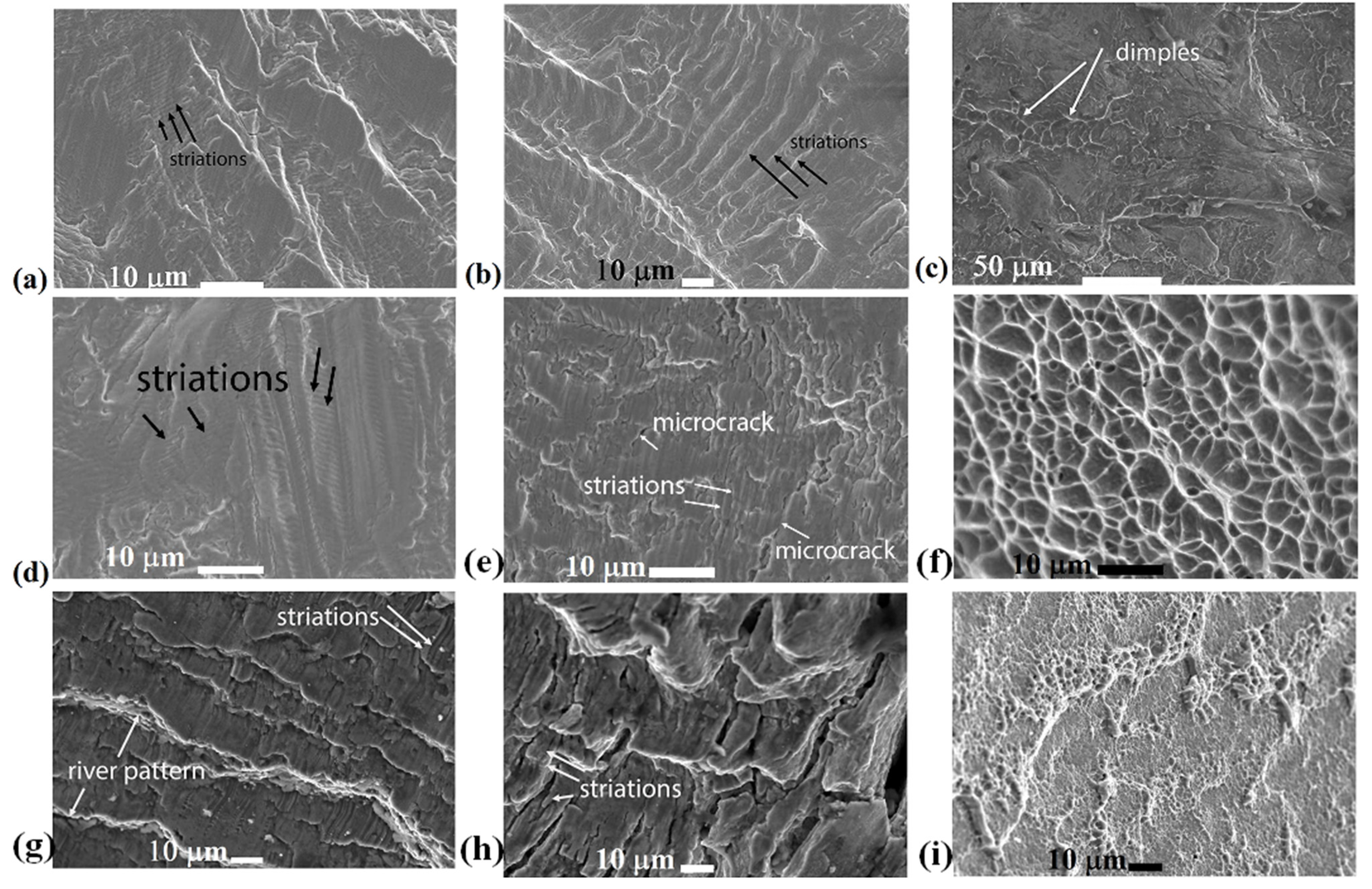
Figure 9 shows images of the surfaces of samples No. 1, 2, and 3, obtained in each fracture zone. In the β-CG samples, ductile non-smooth relief with regular fatigue striations (Figure 9a) with a step of 1.8 ± 0.1 µm were observed in the zone of stable growth of a fatigue crack. The zone of accelerated crack growth in the quenched specimen also had a striated but flatter relief (Figure 9b); the striations were rather wide and had a step of 4.5 ± 0.1 µm. Secondary microcracks were not observed. The overload zone had features of both ductile and brittle fracture with rupture and cleavage planes (Figure 9c). The size of the dimples was commensurate with the size of β-grains, i.e., 10 ± 0.5 µm.
The zone of initiation and stable growth of a fatigue crack in the (α + β)-CG alloy was characterized by a flat relief (Figure 9d). Structureless flat areas, probably formed from the contact of mating surfaces during compression, alternated with a striated relief. Fatigue striations were located perpendicular to the propagation of the main crack; their step was 1.2 ± 0.1 µm. The zone of accelerated growth of a fatigue crack showed areas with fatigue striations with a step of 1.8 ± 0.06 µm (Figure 9e). Secondary microcracks were visible between striations. The overload zone resembled a typical ductile-dimple fracture. Dimples were inhomogeneous in shape and size (Figure 9f). The size of the dimples was in the range of 2–8 µm.
The zone of stable growth of a fatigue crack in the UFG sample had a rough, quasi-brittle relief with steps, on which fatigue striations were located with a step of 2 ± 0.2 µm (Figure 9g). The zone of accelerated growth was characterized by a rough striated relief; deep secondary microcracks were clearly visible between the striations (Figure 9h). Secondary cracking in the UFG sample occurred much more intensively than in (α + β)-CG (Figure 9e). Fatigue striations had a brittle appearance; their step was 4 ± 0.2 µm. In the overload zone, low ductile ridges and flat areas were found with dimples smaller than 1 µm (Figure 9i). The edges of the dimples were quite high compared to their diameter. The dimples in the UFG sample had much smaller sizes than those in the CG samples (Figure 9c,f).
3.2.2. Fractographic Analysis of Fractures of Samples with a Fatigue Life N ≈ 3 × 10⁶
Figure 10 shows a general view of the fracture surfaces of the samples that fractured in the low-cycle fatigue region on the Wöhler curve (No. 4, 5, 6, Figure 6). In the β-CG sample, a fatigue fracture occupied a large part of the surface area. The fracture surface was rather flat (Figure 10a). As shown in the image showing the fracture surface of the (α + β)-CG sample, two radial fatigue cracks formed on the surface, as evidenced by river patterns (Figure 10b). The fatigue fracture zone occupied almost a half of the fracture area but was still smaller than that in the β-CG sample. The fracture surface (α + β)-UFG had a developed non-smooth relief; the relief of zone II was flaky (Figure 10c). The fatigue fracture region, similar to in the (α + β)-CG sample, occupied almost half of the fracture surface.
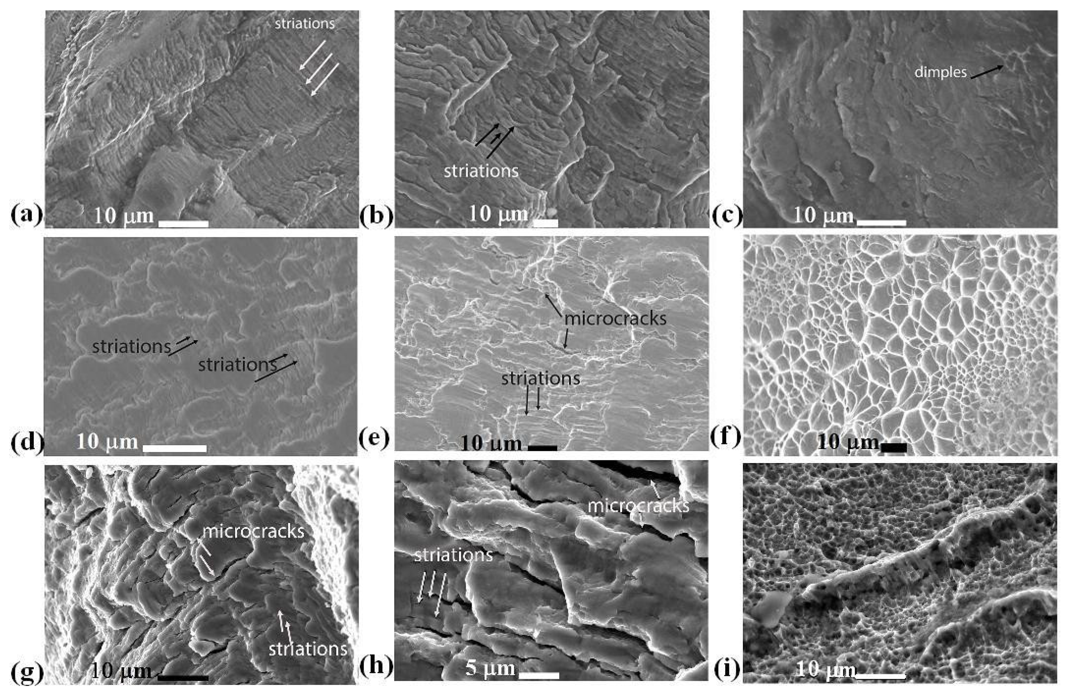
Figure 11 shows the images of each zone of the fracture surface for samples No. 4, 5, 6. The zones of initiation and stable growth of fatigue cracks in the samples after quenching were characterized by a predominantly striated relief with a striation step of 0.7 ± 0.05 µm; flat smooth areas were also observed (Figure 11a). The zone of accelerated propagation of fatigue cracks was of a mixed nature, i.e., from a fatigue striated fracture to a ductile one with the formation of steps and ridges (Figure 11b). The step of the striations was 2.4 ± 0.1 µm. The overload zone was a brittle fracture with steps (Figure 11c). At the same time, there were also local areas with elements of ductile fracture.
In the (α + β)-CG specimen, flat areas with crumpled surface dominated in the zone of initiation and stable growth of a fatigue crack (Figure 11d). There were also fatigue striations with a step of 0.6 ± 0.05 µm. The stage of accelerated growth of the fatigue crack was ductile, and there were fatigue striations (step 1.2 ± 0.1 µm), along which secondary cracking of the material (Figure 11e). The overload zone comprised a ductile-dimple fracture. The dimple size had a rather large range of values, i.e., 0.5–12 µm (Figure 11f).
In the zone of initiation and stable growth of a fatigue crack in the (α + β)-UFG alloy, a ductile uneven fracture was observed (Figure 11g). There were fatigue striations with a step of 1 ± 0.15 µm along which the secondary cracking of the material occurred in the zone of accelerated crack development relief (Figure 11h). The fatigue striations were rough, and secondary microcracks of different depths were visible, located perpendicular to the direction of the main fatigue crack propagation. The step of the striations was 1.4 ± 0.2 µm. The static fracture was a typical ductile fracture; the dimples were much smaller than in the previous specimens (Figure 11i). Groups of dimples had edgings in the form of ductile ridges.
Table 3 presents the striation step in the zones of stable (I) and accelerated (II) fatigue crack growth. It is known that one fatigue striation forms in each test cycle, and the average distance between them corresponds to the average displacement of the crack front in one test cycle, which allowed us to evaluate the local rate of growth of a fatigue crack [44]. One can see that in all the samples, the striation step increased intensively in zone II, which was naturally associated with an increase in the propagation rate of the main crack. The step of striations reduced with a decrease in stress amplitude. The average value of the fatigue striation step at close values of the stress level (670–720 MPa) (Table 3) was smaller in the UFG material (No. 6) than in the CG material (No. 1 and 2), which may indirectly indicate a smaller local rate of propagation of a fatigue crack in the UFG alloy.
On the whole, the formation of a UFG structure did not lead to significant changes in the fatigue fracture behavior of the Ti-15Mo alloy. In general, the nature of the fatigue fractures of samples was typical of titanium alloys, consisting of characteristic regions, i.e., fatigue and static fractures [34]. The surfaces of the fractures in all the samples were matte, predominantly indicating ductile fractures [42]. It can be seen that in all the samples, fatigue cracks originated on the sample surface and propagated inward, perpendicular to the loading direction (Figure 8 and Figure 10). Fatigue striations were clearly visible in the fatigue fracture zone of all samples, typical of titanium alloys [31]. However, a number of distinctive features could be identified.
At high stress amplitudes (in the region of low-cycle fatigue), quenched single-phase β-CG specimens had the most ductile characteristics and a large area of fatigue failure, which was probably associated with the highest ductility (uniform elongation δun = 23 ± 0.5, elongation to failure δ = 35 ± 1%) of the alloy in this state and therefore a better ability to resist crack propagation. The high ductility of β-titanium is due to a bcc lattice, which has a larger number of slip systems compared to α-titanium with an hcp lattice [12]. In ductile CG materials with a long free path of dislocations and a tendency for strain hardening, the effect of fatigue crack closure or crack tip blunting can manifest itself [32].
The fracture surfaces in the samples in the two-phase state had distinctive features. In particular, the (α + β) UFG specimens had a larger area of fatigue failure than the (α + β) CG specimens, despite their limited ductility and lower work hardening capacity, which was characterized by low uniform elongation (δun = 2.5 ± 0.5 in (α + β) UFG state, δun = 10 ± 0.5 in (α + β) CG state). In [31,32] this fact was associated with a greater length of intergranular and interfacial boundaries, which intensified the tortuosity of the fatigue crack trajectory.
The tortuosity of the fatigue crack propagation path in the two-phase UFG state of the alloy was indirectly confirmed by the rougher fracture surface compared to the almost flat fracture relief of β-CG specimens with homogeneous structures. It is known that a fatigue crack, especially during high-cycle tests, is sensitive to microstructure parameters [32,35]; it can go around, propagate along the boundaries, or slow down when it encounters α-particles that are harder than the matrix [12].
It should be noted that more secondary cracks along fatigue striations were observed in the UFG samples than in the CG ones; this was caused by the higher internal stresses of the UFG state (see Figure 9 and Figure 11). The appearance of secondary cracks reduced the driving force of main crack propagation, as it induced stress relief at the crack tip and slowed crack development [32].
Finally, the dimples in the static rupture zone in the (α + β) UFG samples were much smaller than in (α + β) CG and had a smaller depth, which indicated a flatter relief in this zone, and consequently, lower fracture toughness [42]. This was evidently associated with the lower ductility of the UFG alloy during static tension.
4. Conclusions
The results of this study on the fatigue behavior and fracture features of Ti-15Mo metastable β-alloy in three structure and phase states—initial (α + β)-CG, β-CG after solid solution treatment from 810 °C, and (α + β)-UFG after ECAP-C and drawing—showed the following:
- The best values of ultimate tensile strength (1590 MPa) and fatigue endurance limit (710 MPa) were obtained in the alloy with two-phase (α + β)-UFG structure due to the significant size reduction in β-grains, i.e., to 150 nm, grains of αp-phase to 480 nm, and the precipitation of particles of the secondary αs-phase with a size of 30 nm and a volume fraction of 37% during TMT.
- The UFG (α + β) state demonstrated the highest resistance to high-cycle fatigue and was characterized by a larger area of fatigue fracture development in the UFG sample, high relief roughness, and the presence of secondary cracks along fatigue striations, which had a beneficial effect on stress relief at the tip of the main crack.
Author Contributions
Conceptualization, S.A.G. and V.V.P. and I.P.S.; methodology, S.A.G. and I.M.M.; investigation, S.A.G. and V.V.P.; data curation, S.A.G. and I.M.M.; writing—review and editing, S.A.G. and I.P.S.; supervision, I.P.S. All authors have read and agreed to the published version of the manuscript.
Funding
This research was funded by the Russian Science Foundation, grant number 21-79-10167.
Institutional Review Board Statement
Not applicable.
Informed Consent Statement
Not applicable.
Data Availability Statement
Not applicable.
Conflicts of Interest
The authors declare no conflict of interest.
References
- Lütjering, G.; Williams, J.C.T. Engineering Materials, Processes; Springer: Berlin/Heidelberg, Germany, 2007. [Google Scholar]
- Niinomi, M.; Nakai, M.; Hieda, J. Development of new metallic alloys for biomedical applications. Acta Biomater. 2012, 8, 3888–3903. [Google Scholar] [CrossRef]
- Geetha, M.; Singh, A.K.; Asokamani, R.; Gogia, A.K. Ti Based Biomaterials, the Ultimate Choice for Orthopaedic Implants—A Review. Progr. Mater. Sci. 2009, 54, 397–425. [Google Scholar] [CrossRef]
- An, J.; Yu, Z.; Duan, H.; Tian, Y.; Chen, Y. Mild Wear and Severe Wear Behavior of Ti-6Al-4V Alloy at Low, Intermediate and High Sliding Speeds. Surf. Topogr. Metrol. Prop. 2021, 9, 035047. [Google Scholar] [CrossRef]
- Ho, W.F.; Ju, C.P.; Lin, J.H.C. Structure and Properties of Cast Binary Ti–Mo Alloys. Biomaterials 1999, 20, 2115–2122. [Google Scholar] [CrossRef] [PubMed]
- Gain, A.K.; Zhang, L.; Quadir, M.Z. Composites Matching the Properties of Human Cortical Bones: The Design of Porous Titanium-Zirconia (Ti-ZrO2) Nanocomposites Using Polymethyl Methacrylate Powders. Mater. Sci. Eng. A 2016, 662, 258–267. [Google Scholar] [CrossRef]
- Zhang, L.-C.; Chen, L.-Y. A Review on Biomedical Titanium Alloys: Recent Progress and Prospect. Adv. Eng. Mater. 2019, 21, 1801215. [Google Scholar] [CrossRef] [Green Version]
- Li, H.F.; Zheng, Y.F. Recent Advances in Bulk Metallic Glasses for Biomedical Applications. Acta Biomater. 2016, 36, 1–20. [Google Scholar] [CrossRef]
- Costa, B.C.; Tokuhara, C.K.; Rocha, L.A.; Oliveira, R.C.; Lisboa-Filho, P.N.; Costa Pessoa, J. Vanadium ionic species from degradation of Ti-6Al-4V metallic implants: In vitro cytotoxicity and speciation evaluation. Mater. Sci. Eng. C 2019, 96, 730–739. [Google Scholar] [CrossRef]
- Cardoso, G.C.; Buzalaf, M.A.R.; Correa, D.R.N.; Grandini, C.R. Effect of Thermomechanical Treatments on Microstructure, Phase Composition, Vickers Microhardness, and Young’s Modulus of Ti-xNb-5Mo Alloys for Biomedical Applications. Metals 2022, 12, 788. [Google Scholar] [CrossRef]
- Nunes, A.; Borborema, S.; Araújo, L.; Malet, L.; Dille, J.; Almeida, L. Influence of thermo-mechanical processing on structure and mechanical properties of a new metastable β Ti–29Nb–2Mo–6Zr alloy with low Young’s modulus. J. Alloys Compd. 2020, 820, 153078. [Google Scholar] [CrossRef]
- Karasevskaya, O.P.; Ivasishin, O.M.; Semiatin, S.L.; Matviychuk, Y.V. Deformation behavior of beta-titanium alloys. Mater. Sci. Eng. A 2003, 354, 121–132. [Google Scholar] [CrossRef]
- Sun, F.; Zhang, J.Y.; Vermaut, P.; Choudhuri, D.; Alam, T.; Mantri, S.A.; Svec, P.; Gloriant, T.; Jacques, P.J.; Banerjee, R.; et al. Strengthening strategy for a ductile metastable β-titanium alloy using low-temperature aging. Mater. Res. Let. 2017, 5, 547–553. [Google Scholar] [CrossRef] [Green Version]
- Cheng, J.; Wang, H.; Li, J.; Gai, J.; Ru, J.; Du, Z.; Fan, J.; Niu, J.; Song, H.; Yu, Z. The Effect of Cold Swaging Deformation on the Microstructures and Mechanical Properties of a Novel Metastable β Type Ti–10Mo–6Zr–4Sn–3Nb Alloy for Biomedical Devices. Front. Mater. 2020, 7, 228. [Google Scholar] [CrossRef]
- Marquardt, B.; Shetty, R. Beta Titanium Alloy Processed for High Strength Orthopedic Applications. J. ASTM Int. 2005, 2, 71–82. [Google Scholar] [CrossRef]
- Cojocaru, V.D.; Șerban, N. Effects of Solution Treating on Microstructural and Mechanical Properties of a Heavily Deformed New Biocompatible Ti–Nb–Zr–Fe Alloy. Metals 2018, 8, 297. [Google Scholar] [CrossRef] [Green Version]
- Ho, W.F. A comparison of tensile properties and corrosion behavior of cast Ti-7,5Mo with c.p, Ti-15Mo and Ti-6Al-4V alloys. J. Alloys Compd. 2008, 464, 580–583. [Google Scholar] [CrossRef]
- ASTM F 2066; Standard Specification for Wrought Titanium-15Molybdenum Alloy for Surgical Implant Applications (UNS R58150). Annual Book of ASTM Standards; ASTM International: West Conshohocken, PA, USA, 2018.
- Jablokov, V.R.; Nutt, M.J.; Richelsoph, M.E.; Freese, H.L. The Application of Ti-15Mo Beta Titanium Alloy in High Strength Structural Orthopaedic Applications; ASTM International: West Conshohocken, PA, USA, 2005; Volume 2. [Google Scholar]
- Bowen, A.W. Strength Enhancement in metastable β-titanium alloy: Ti-15Mo. J. Mater. Sci. 1977, 12, 1355–1360. [Google Scholar] [CrossRef]
- Langdon, T.G. Twenty-five years of ultrafine-grained materials: Achieving exceptional properties through grain refinement. Acta Mater. 2013, 61, 7035–7059. [Google Scholar] [CrossRef]
- Ovid’ko, I.A.; Valiev, R.Z.; Zhu, Y.T. Review on superior strength and enhanced ductility of metallic nanomaterials. Prog. Mater. Sci. 2018, 94, 462–540. [Google Scholar] [CrossRef]
- Valiev, R.Z.; Islamgaliev, R.K.; Alexandrov, I.V. Bulk Nanostructured Materials from Severe Plastic Deformation. Prog. Mater. Sci. 2000, 45, 103–189. [Google Scholar] [CrossRef]
- Bartha, K.; Stráský, J.; Veverková, A.; Barriobero-Vila, P.; Lukáč, F.; Doležal, P.; Sedlák, P.; Polyakova, V.; Semenova, I.; Janeček, M. Effect of the High-Pressure Torsion (HPT) and Subsequent Isothermal Annealing on the Phase Transformation in Biomedical Ti15Mo Alloy. Metals 2019, 9, 1194. [Google Scholar] [CrossRef] [Green Version]
- Jiang, B.; Emura, S.; Tsuchiya, K. Formation of equiaxed α phase in Ti-5Al-5Mo-5V-3Cr alloy deformed by high-pressure torsion. J. Alloys Compd. 2018, 738, 283–291. [Google Scholar] [CrossRef]
- Godoy, D.; Jorge, A.; Kiminami, C.; Bolfarini, C.; Botta, W. Ultrafine-Grained Ti-13Nb-13Zr Alloy Produced by Severe Plastic Deformation. Mater. Res. 2017, 20, 404–410. [Google Scholar] [CrossRef] [Green Version]
- Bartha, K.; Stráský, J.; Barriobero-Vila, P.; Šmilauerová, J.; Doležal, P.; Veselý, J.; Semenova, I.; Polyakova, V.; Janeček, M. In-situ investigation of phase transformations in ultra-fine grained Ti15Mo alloy. J. Alloys Compd. 2021, 867, 159027. [Google Scholar] [CrossRef]
- Naydenkin, E.V.; Mishin, I.P.; Ratochka, I.V.; Oborin, V.A.; Bannikov, M.V.; Bilalov, D.A.; Naydenkin, K.E. Fatigue and fracture behavior of ultrafine-grained near β titanium alloy produced by radial shear rolling and subsequent aging. Mater. Sci. Eng. A 2021, 810, 140968. [Google Scholar] [CrossRef]
- Sheremetyev, V.; Kudryashova, A.; Dubinskiy, S.; Galkin, S.; Prokoshkin, S.; Brailovski, V. Structure and functional properties of metastable beta Ti-18Zr-14Nb (at.%) alloy for biomedical applications subjected to radial shear rolling and thermomechanical treatment. J. Alloys Compd. 2018, 737, 678–683. [Google Scholar] [CrossRef]
- Mairambekova, A.M.; Eroshenko, A.Y.; Oborin, V.A.; Bannikov, M.V.; Chebodaeva, V.V.; Terekhina, A.I.; Naimark, O.B.; Dmitriev, A.I.; Sharkeev, Y.P. Characteristic Features of Ultrafine-Grained Ti-45 wt.% Nb Alloy under High Cycle Fatigue. Materials 2021, 14, 5365. [Google Scholar] [CrossRef]
- Semenova, I.P.; Modina, Y.M.; Stotskiy, A.G.; Polyakov, A.V.; Pesin, M.V. Fatigue Properties of Ti Alloys with an Ultrafine Grained Structure: Challenges and Achievements. Metals 2022, 12, 312. [Google Scholar] [CrossRef]
- Estrin, Y.; Vinogradov, A. Fatigue behaviour of light alloys with ultrafine grain structure produced by severe plastic deformation: An overview. Int. J. Fatigue 2010, 32, 898–907. [Google Scholar] [CrossRef]
- Vinogradov, A.Y.; Stolyarov, V.V.; Hashimoto, S.; Valiev, R.Z. Cyclic behavior of ultrafine-grain titanium produced by severe plastic deformation. Mater. Sci. Eng. A 2001, 318, 163–173. [Google Scholar] [CrossRef]
- Saitova, L.; Hoppel, H.; Goken, M.; Semenova, I.; Valiev, R. Cyclic deformation behavior and fatigue lives of ultrafine-grained Ti-6AL-4V ELI alloy for medical use. Int. J. Fatigue 2009, 31, 322–331. [Google Scholar] [CrossRef]
- Vinogradov, A. Fatigue limit and crack growth in ultra-fine grain metals produced by severe plastic deformation. J. Mater. Sci. 2006, 42, 1797–1808. [Google Scholar] [CrossRef]
- Gatina, S.A.; Polyakova, V.V.; Polyakov, A.V.; Semenova, I.P. Microstructure and Mechanical Properties of β-Titanium Ti-15Mo Alloy Produced by Combined Processing including ECAP-Conform and Drawing. Materials 2022, 15, 8666. [Google Scholar] [CrossRef] [PubMed]
- ATI Ti15Mo Technical Data Sheet. 2014. Available online: https://www.atimaterials.com/Products/Documents/datasheets/titanium/alloyed/ati_15Mo_Titanium_Alloy_en_v4%20final.pdf (accessed on 23 April 2014).
- Raab, G.I.; Gunderov, D.V.; Valiev, R.Z.; Baushev, N.G. Method for Deformation Processing of a Metal Workpiece in the Form of a Bar. RF Patent No. 2417857, 5 October 2011. [Google Scholar]
- Scardi, P.; Lutterotti, L.; Di Maggio, R. Size-Strain and quantitative analysis by the Rietveld method. Adv. X-ray Anal. 1991, 35, 69–75. [Google Scholar] [CrossRef]
- Gleiter, H. Nanostructured Materials: Basic Concepts and Microstructure. Acta Mater. 2000, 48, 1–29. [Google Scholar] [CrossRef] [Green Version]
- Ivasishin, O.M.; Markovsky, P.E.; Matviychuk, Y.V.; Semiatin, S.L. Precipitation and recrystallization behavior of beta titanium alloys during continuous heat treatment. Metall. Mater. Trans. A 2003, 34, 147–158. [Google Scholar] [CrossRef]
- Terent’ev, V.F. Fatigue Strength of Metals and Alloys; Intermet Engineering: Moscow, Russia, 2002; p. 288. [Google Scholar]
- Zherebtsov, S.; Salishchev, G.; Galeyev, R.; Maekawa, K. Mechanical Properties of Ti–6Al–4V Titanium Alloy with Submicrocrystalline Structure Produced by Severe Plastic Deformation. Mater. Trans. 2005, 46, 2020–2025. [Google Scholar] [CrossRef] [Green Version]
- Zhang, J.; Jiang, Y. Fatigue of polycrystalline copper with different grain sizes and texture. Int. J. Plast. 2006, 22, 536–556. [Google Scholar] [CrossRef]
Figure 1.
Schematic of the combined thermomechanical treatment of Ti-15Mo (a); ECAP-Conform process (b); drawing of the billet after ECAP-C, ready to be drawn (c).
Figure 1.
Schematic of the combined thermomechanical treatment of Ti-15Mo (a); ECAP-Conform process (b); drawing of the billet after ECAP-C, ready to be drawn (c).

Figure 2.
Schematic of samples for (a) tensile testing and (b) fatigue testing.

Figure 3.
Microstructure of CG Ti-15Mo: (a) Initial (α + β)-state, longitudinal section, SEM; (b) EDS profile of the (α + β)-state; (c) β-state after quenching, OM.
Figure 3.
Microstructure of CG Ti-15Mo: (a) Initial (α + β)-state, longitudinal section, SEM; (b) EDS profile of the (α + β)-state; (c) β-state after quenching, OM.

Figure 4.
Microstructure of UFG Ti-15Mo: (a,b) Cross section; (c,d) Longitudinal section. TEM.

Figure 5.
Typical engineering tensile curves for Ti-15Mo in CG (α + β), β- and UFG (α + β)-states.

Figure 6.
Wöhler fatigue curves (S-N) for Ti-15Mo in the CG and UFG states. 1, 2, 3: samples with a fatigue life of N < 104; 4, 5, 6: samples with a fatigue life of N ≈ 3 × 10⁶
Figure 6.
Wöhler fatigue curves (S-N) for Ti-15Mo in the CG and UFG states. 1, 2, 3: samples with a fatigue life of N < 104; 4, 5, 6: samples with a fatigue life of N ≈ 3 × 10⁶

Figure 7.
Proportionality between the tensile strength and the fatigue endurance limit in Ti-15Mo.

Figure 8.
General view of the fracture surface of the samples with a fatigue life N < 10 4 in (a) β-CG, (b) (α + β)-CG, and (c) (α + β)-UFG states. The arrows show the direction of fatigue crack propagation.
Figure 8.
General view of the fracture surface of the samples with a fatigue life N < 10 4 in (a) β-CG, (b) (α + β)-CG, and (c) (α + β)-UFG states. The arrows show the direction of fatigue crack propagation.

Figure 9.
Fracture relief in the Ti-15Mo samples with fatigue life N = 7 × 10³ (samples No. 1, 2, 3): (a–c) β-CG; (d–f) (α + β)-CG; (g–i) (α + β)-UFG state. (a,d,g) Zone of initiation and stable growth of a fatigue crack; (b,e,h) zone of accelerated growth of a fatigue crack; (c,f,i) overload zone.
Figure 9.
Fracture relief in the Ti-15Mo samples with fatigue life N = 7 × 10³ (samples No. 1, 2, 3): (a–c) β-CG; (d–f) (α + β)-CG; (g–i) (α + β)-UFG state. (a,d,g) Zone of initiation and stable growth of a fatigue crack; (b,e,h) zone of accelerated growth of a fatigue crack; (c,f,i) overload zone.

Figure 10.
General view of the fracture surface of the samples with a fatigue life N = 3 × 10⁶ in the (a) β-CG, (b) (α + β)-CG, and (c) (α + β)-UFG states. The arrows show the direction of fatigue crack propagation.
Figure 10.
General view of the fracture surface of the samples with a fatigue life N = 3 × 10⁶ in the (a) β-CG, (b) (α + β)-CG, and (c) (α + β)-UFG states. The arrows show the direction of fatigue crack propagation.

Figure 11.
Fracture relief in Ti-15Mo samples with fatigue life N = 3 × 10⁶ (samples №4,5,6): (a–c) β-CG; (d–f) (α + β)-CG; (g–i) (α + β)-UFG state. (a,d,g) Zone of initiation and stable growth of a fatigue crack; (b,e,h) Zone of accelerated growth of a fatigue crack; (c,f,i) Overload zone.
Figure 11.
Fracture relief in Ti-15Mo samples with fatigue life N = 3 × 10⁶ (samples №4,5,6): (a–c) β-CG; (d–f) (α + β)-CG; (g–i) (α + β)-UFG state. (a,d,g) Zone of initiation and stable growth of a fatigue crack; (b,e,h) Zone of accelerated growth of a fatigue crack; (c,f,i) Overload zone.


Table 1.
Chemical composition of Ti-15Mo according to the material certificate.
| Ti | Mo | O | Fe | C | N |
|---|---|---|---|---|---|
| balance | 15.2 | 0.16 | 0.02 | 0.008 | 0.10 |
Table 2.
Mechanical properties of medical-grade Ti alloys in different structural states.
| Alloy | σuts, MPa | σ−1, MPa | σ−1/σuts |
|---|---|---|---|
| (β)-Ti-15Mo CG | 800 | 410 | 0.51 |
| (α+β)-Ti-15Mo CG | 1017 | 500 | 0.49 |
| (α+β)-Ti-15Mo UFG | 1590 | 710 | 0.45 |
| Ti-6Al-4V ELI CG [43] | 960 | 580 | 0.6 |
| Ti-6Al-4V ELI UFG [43] | 1300 | 690 | 0.53 |
| Ti Grade 4 CG [33] | 460 | 238 | 0.52 |
| Ti Grade 4 UFG [33] | 810 | 380 | 0.48 |
Table 3.
Average step of fatigue striations in Ti-15Mo in CG and UFG states in µm.
| Fatigue Life | N < 104 | N ≈ 3 × 10⁶ | ||||||
|---|---|---|---|---|---|---|---|---|
| State of Alloy | # | σ−1, MPa | I | II | # | σ−1, MPa | I | II |
| CG (β) | 1 | 670 | 1.8 ± 0.9 | 4.5 ± 0.1 | 4 | 430 | 0.7 ± 0.05 | 2.4 ± 0.1 |
| CG (α+β) | 2 | 695 | 1.2 ± 0.1 | 1.8 ± 0.06 | 5 | 545 | 0.6 ± 0.05 | 1.2 ± 0.1 |
| UFG (α+β) | 3 | 825 | 2 ± 0.2 | 4 ± 0.2 | 6 | 720 | 1 ± 0.15 | 1.4 ± 0.2 |
Disclaimer/Publisher’s Note: The statements, opinions and data contained in all publications are solely those of the individual author(s) and contributor(s) and not of MDPI and/or the editor(s). MDPI and/or the editor(s) disclaim responsibility for any injury to people or property resulting from any ideas, methods, instructions or products referred to in the content. |
© 2023 by the authors. Licensee MDPI, Basel, Switzerland. This article is an open access article distributed under the terms and conditions of the Creative Commons Attribution (CC BY) license (https://creativecommons.org/licenses/by/4.0/).
Share and Cite
MDPI and ACS Style
Gatina, S.A.; Polyakova, V.V.; Modina, I.M.; Semenova, I.P. Fatigue Behavior and Fracture Features of Ti-15Mo Alloy in β-, (α + β)-, and Ultrafine-Grained Two-Phase States. Metals 2023, 13, 580. https://doi.org/10.3390/met13030580
AMA Style
Gatina SA, Polyakova VV, Modina IM, Semenova IP. Fatigue Behavior and Fracture Features of Ti-15Mo Alloy in β-, (α + β)-, and Ultrafine-Grained Two-Phase States. Metals. 2023; 13(3):580. https://doi.org/10.3390/met13030580
Chicago/Turabian StyleGatina, Svetlana A., Veronika V. Polyakova, Iuliia Mikhailovna Modina, and Irina P. Semenova. 2023. "Fatigue Behavior and Fracture Features of Ti-15Mo Alloy in β-, (α + β)-, and Ultrafine-Grained Two-Phase States" Metals 13, no. 3: 580. https://doi.org/10.3390/met13030580
Note that from the first issue of 2016, this journal uses article numbers instead of page numbers. See further details here.