
New Equipment and Method for Refining the Solidified Grain Structure


1
Institute of Physical Metallurgy, Metal Forming and Nanotechnology, University of Miskolc, H-3515 Miskolc, Hungary
2
MTA-ME Materials Science Research Group, ELKH, H-3515 Miskolc, Hungary
*
Author to whom correspondence should be addressed.
Metals 2022, 12(4), 658; https://doi.org/10.3390/met12040658
Submission received: 6 December 2021
/
Revised: 7 March 2022
/
Accepted: 28 March 2022
/
Published: 12 April 2022
(This article belongs to the Special Issue Solidification Process of Alloys under Magnetic Field)
Abstract
:The mechanical properties of solidified alloys strongly depend on the grain size. In many practical cases at the given solidification parameters (temperature gradient and solid/liquid interface velocity), the solidified microstructure is columnar, meaning that the mechanical properties differ depending on the direction, which results in the material being unsuitable for application. The microstructure can be changed from columnar to equiaxed through the inclusion of grain refinement material. This strategy is well known in the literature as the columnar/equiaxed transition (CET). In some cases, it is beneficial if the CET can be produced without using grain refinement material; for example, it may detrimentally affect the mechanical properties (such as when the Al alloy ingot is used in pressing). The stirring of the melt as an alternative for the use of grain refinement material could solve this problem as intensive melt flow can break some particles from growing dendrites. This paper demonstrates a new type of traveling magnetic field inductor that is used to produce strong shearing stress in the flow perpendicular to the solidification front by causing part of the metallic melt layers touching each other to flow in an opposite direction. Through some examples, we demonstrate the effect of stirring by the new inductor on the solidified grain structure.
1. Introduction
The mechanical properties of solidified materials (tensile strength, hardness, and elongation) are influenced and significantly determined by the grain size and distribution, which develop during the solidification process. In the course of the solidification process, a so-called columnar structure can develop within certain values of the solidification parameters (solidification front rate and temperature gradient), as a result of which the properties of the workpiece observed in one direction differ from those observed in other directions (e.g., the tensile strength is much higher in the direction parallel to the columns than in the direction perpendicular to the columns). This is a situation that is, therefore, usually undesired (except for special cases, e.g., in single-crystal turbine blades). Even though no columnar structure develops during solidification, a solid workpiece consisting of large crystals can develop due to the so-called homogeneous nucleation process. Moreover, owing to heterogeneous nucleation developing on the mold wall, the resulting grain structure is finer on the surface of the workpiece touching the solidification unit (mold wall) than inside the workpiece.
The aim of this work was to develop equipment and an associated method suitable for refining the grain structure that develops during the solidification process.
2. Methods of Grain Refinement
2.1. Grain Refinement by Grain Refinement Material
Different technologies are known to be applicable for developing the fine, equiaxed grain structure that is approximately identical at any point in each workpiece. The basis of each technology is that certain kinds of solid particles are added to the melt; these solid particles cause heterogeneous nucleation (similar to the mold wall), i.e., the nuclei develop on these surfaces while the value for the melt overcooling is much lower [1,2,3].
The workpiece will develop a fine grain structure if a suitable quantity of solid particles is added to the melt. This process is called grain refinement, and the added material is called grain refinement material.
To exhibit this function, the grain refinement particle must meet the following conditions:
- (i)
- It must be wetted in the solidified solid phase;
- (ii)
- It must be in a solid state at the solidification temperature, i.e., it must not melt or dissolve during the technological process;
- (iii)
- It must not sediment or float (particles must have nearly identical densities);
- (iv)
- It must not significantly change the workpiece’s physical and mechanical properties.
It is not easy to find a suitable grain refinement material for different alloys. Al–5% Ti–1% B alloy is successfully used in the case of the Al alloys, where TiB2 particles are the grain refinement material. No effective grain refinement materials are known in the case of the steels and Cu-based alloys. It is especially difficult to find such a material in the case of steels due to their very high melt temperatures. Some materials that would be suitable as far as their melting point is concerned can, however, significantly worsen the mechanical properties.
Another possibility is adding base-metal oxides, e.g., during the mechanical stirring of the melt [4]. Oxides develop on the melt surface if they are not protected from oxidation or are deliberately oxidized; these oxides can be mixed into the melt by flowing the melt. The melting point of oxides is generally higher than that of the base metal. The problem when using this technology is that it is difficult to manage and, in many cases, the oxide is not wetted by the solid alloy (i.e., (i) condition cannot be fulfilled). It is also very difficult to find a stirring blade made of a material suitably robust for long-term mechanical stirring, especially at high temperatures (steels). Oxide ceramics are rigid and fragile, and graphite burns in oxidizing atmospheres and readily wears due to its low strength.
2.2. Grain Refinement by Own Particles
A so-called mushy zone develops during the solidification process of alloys of the solid–solution type (containing at least partial solid solution). This is due to the alloys solidifying in the temperature range. Both the solid and the melt phases can be found coexisting in the mushy zone. Small particles can be broken off from the solid phase (from the dendrites) through the intensive melt flow developed by mechanical stirring. These small solid particles will be the “grain-refining material”. In principle, this technology can be successful when no traditional grain-refining material is available. In practice, it is practically very difficult to perform this process. The problem is that, as mentioned, it would be necessary to place a stirring blade in the solidification unit during the continuous steel casting process that can withstand the very high temperature (higher than 1700 °C) and the very strong mechanical stress.
2.3. Grain Refinement by Magnetic Field Stirring
Melts possessing electrical conductivity can be forced to flow according to a magnetohydrodynamic process through the use of alternating magnetic fields. Suitable melts are those of metals and metallic alloys (henceforth referred to as metallic melts). The characteristic features of the flow are determined by the specific parameters of the alternating magnetic field.
Small particles can also be broken off from the solid phase in the mushy zone by flowing the metallic melts via magnetic field stirring if the intensity of flows is higher than a limiting value in the solidifying metallic melts. The following types of magnetic fields can be used for stirring: the pulsating, the rotating, and the traveling magnetic field.
In the case of flowing the metallic melt using a pulsating magnetic field, the intensity of the melt flow is significantly lower than the flow realized by rotating or traveling magnetic fields for a similar given electrical energy consumption. A further disadvantage of this method is that controlling the direction and intensity of the flow is complicated.
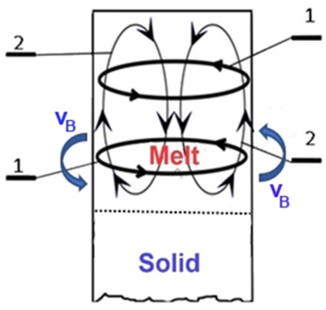
It seems reasonable to flow the metallic melt using a rotating magnetic field (RMF) parallel to the solidification front [5,6,7,8]. A sketch of the flow can be seen in Figure 1. When using an RMF for flowing, two types of macrosegregation can be observed if the field is large enough to cause grain refinement via separation of the many solid particles through the melt flow developed by the RMF [9]. Under the influence of the primary flow (parallel to the solidification front, “1”), macrosegregation develops in the middle or at the edge of the workpiece. Furthermore, under the influence of the secondary flow (that has a much lower intensity than the intensity of the primary flow, “2”), when delivering the alloying elements from the mushy zone perpendicular to the solidification front, macrosegregation develops in the direction of the longitudinal axis of the workpiece. Consequently, this type of magnetic stirring is impractical, though it can lead to grain refinement to a certain extent.
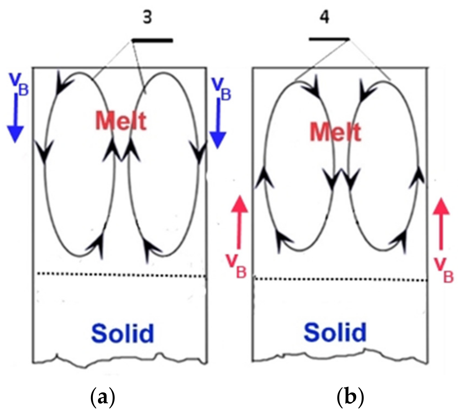
The metallic melt can flow using a traveling magnetic field (TMF) perpendicular to the solidification front if the velocity of this traveling magnetic field is identical or opposite to the direction in which the solidification front is moving (Figure 2) [10,11,12,13,14].
The force acting on the metallic melt, being in a crucible placed in the longitudinal axis of the TMF inductor of the vertical axis, is either upwards or downwards, parallel to the melt axis, depending on the phase series of excitation associated with the inductor.
In this case, the Lorentz force parallel to the axis of metallic melt, i.e., in the same direction, acts on the entire metallic melt. The intensity of the force (the pressure developed by the force) changes as a function of the radius. As a result, flow develops in the metallic melt. In this case, the metallic melt flows upwards along the wall of the crucible (“3”) if the direction of the traveling magnetic field is upwards, and it flows in the opposite direction in the middle of the crucible. Thus, two flow loops develop. The flow direction of the melt changes both along the crucible wall and in the middle of the crucible if the direction of the traveling magnetic field is downwards (“4”). The sketch of the flow can be seen in Figure 2a,b. The magnetic field moves from upwards to downwards in Figure 2a and vice versa in Figure 2b.
Two types of TMF inductors are used. The cylindric (tube) construction is most frequently applied, and its advantage is its simple construction [9,11]. The other TMF inductor has a plane arrangement. It is used rarely because its coil system is much more complicated than the RMF inductor [10]. The advantage of having a plane arrangement compared to the TMF inductor of tube construction (in the case of identical geometry) is that much less electrical power is necessary for ensuring a unit value of magnetic induction developing in the melt.
The images of the developing melt flow in the melt are similar for both types of TMF inductors (Figure 2a,b).
Thus, both types of flow can break solid particles from the dendrites in the mushy zone and bring them to the liquid phase; consequently, grain refinement can be observed. However, the disadvantage of these TMF inductors is that suitable grain refinement can only be ensured by using a very high magnetic field (i.e., a very high electrical power).
It is possible to combine the RMF and TMF inductors [14,15]. In principle, flows parallel to the solidification front and perpendicular to it can develop using this solution. A possible arrangement is demonstrated in [16].
In this case, a TMF inductor with a cylindrical arrangement can be seen inside, and an RMF inductor consisting of six poles can be found outside. This is an air-core solution whereby a large amount of electrical power is necessary to ensure high magnetic induction in the melt. Moreover, the magnetic field of one of the types of inductor (the RMF type inductor) generates an eddy current in the coils of the other type of inductor (TMF); so, more heat develops within. The magnetic field of the RMF inductor is shielded to a certain extent by the coils of the TMF inductor. Owing to the abovementioned facts, only a flow of low intensity can develop in the melt compared with what is necessary for grain refinement. In the case of choosing the iron-core solution instead of the air-core solution, the iron cores entirely block the effect of any of the TMF and RMF inductor parts. Thus, this solution cannot be applied for grain refinement in practice.
Generation of a flow able to cause a significant extent of grain refinement to develop in the melt requires a very high magnetic field (with very high electrical energy consumption) in the magnetic stirring units described above because the melt and the particles touching each other move in the same direction (Figure 1 and Figure 2).
3. New Equipment
3.1. The Principle of the Developed TMF Facility
Our purpose was to eliminate the disadvantages of the described solutions, i.e., to create a method and equipment by which grain refinement can be realized with minimum macrosegregation, in such a way that, during the solidification process, the stirring takes place with a magnetic field by using less electrical energy than that applied in the methods mentioned above. [17]
It was necessary to construct a new type of magnetic inductor for the stirring unit of the equipment, realizing the new method by which a flow of high shearing stress can develop in the mushy zone. At the same time, the electrical energy consumption is less than that of the traditional magnetic stirring equipment.
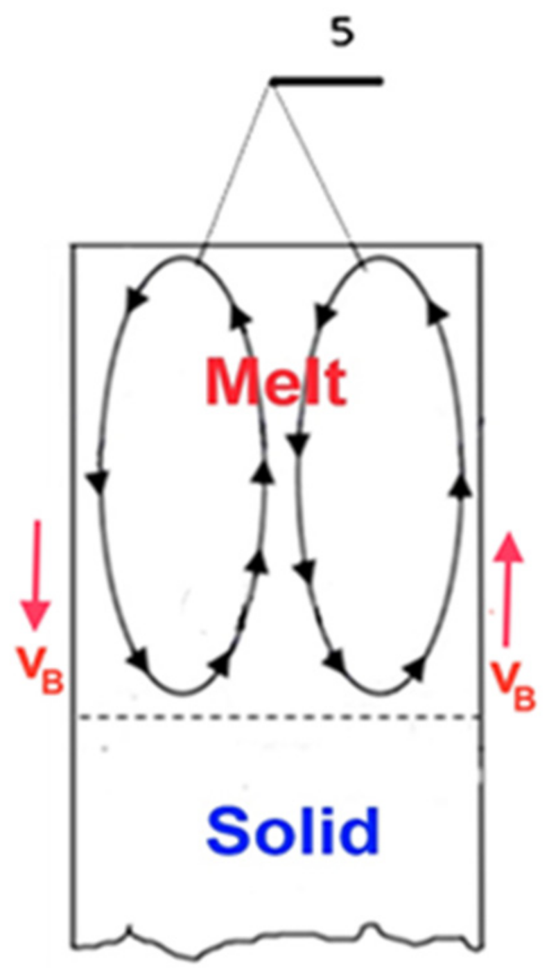
We were able to solve this task by recognizing the fact that an eddy current and a significant shearing stress develop in the melt when the TMF inductor of the equipment performing the stirring of the metallic melt is built in such a way that it is able to create flow zones with opposite directions (“5” in Figure 3).
For this, the special TMF inductor of the equipment has an effect such that the metallic melt can flow perpendicular to the direction of the traveling solidification front and parallel to the direction of the traveling front.
The inductor of the equipment produces the most significant shearing stress to develop where the flow is perpendicular to the solidification front by causing part of the metallic melt layers touching each other to flow in an opposite direction. Very strong turbulence develops under the influence of the flow of the metallic melt layers flowing in the opposite direction (in the case of a magnetic field of a given value); this turbulent flow causes a high quantity of particles to break off from the solid dendrites in the mushy zone and transports them to the melt/solid front, where they appear to act as particle nuclei, thus ensuring significant grain refinement.
Macrosegregation can be eliminated by changing the flow directions via changing the direction of the traveling magnetic field using a given frequency.
The solidification equipment uses one TMF twin inductor for flowing the metallic melt. The construction of this TMF twin inductor is significantly different from that of the traditional magnetic stirrers, with a closed magnetic circuit [17]. This TMF twin inductor with a closed magnetic circuit can be derived from any RMF inductor with an even pole-pair number. The derivation steps are demonstrated using an RMF inductor with two pole-pair numbers (4 poles). The steps of the derivation can be seen in Figure 4, Figure 5, Figure 6, Figure 7, Figure 8, Figure 9.
Step 1:
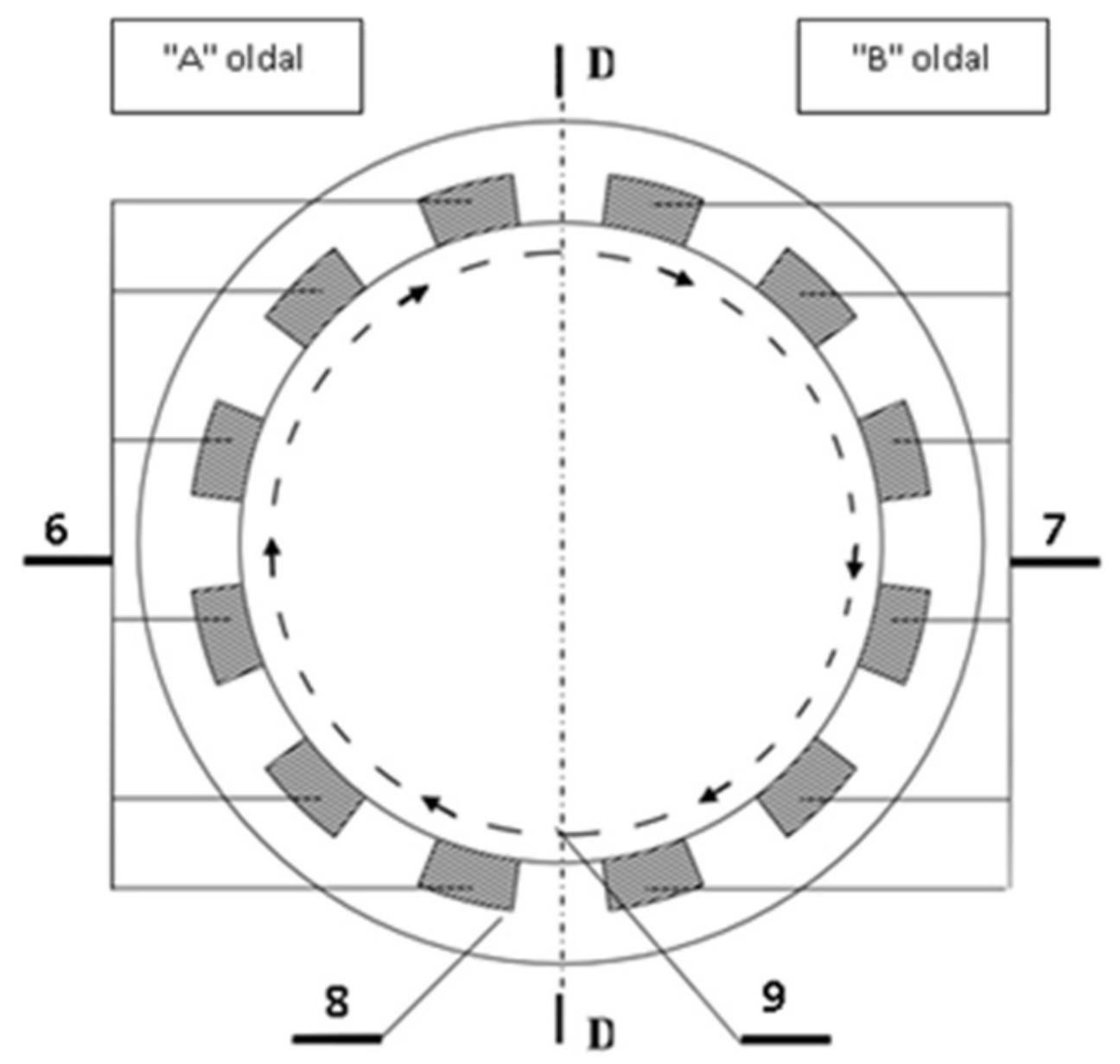
The RMF inductor has two pole pairs (4 poles), as seen in Figure 4. It is cut into two parts (“A” and “B” sides) by the D–D section plane.
Step 2:
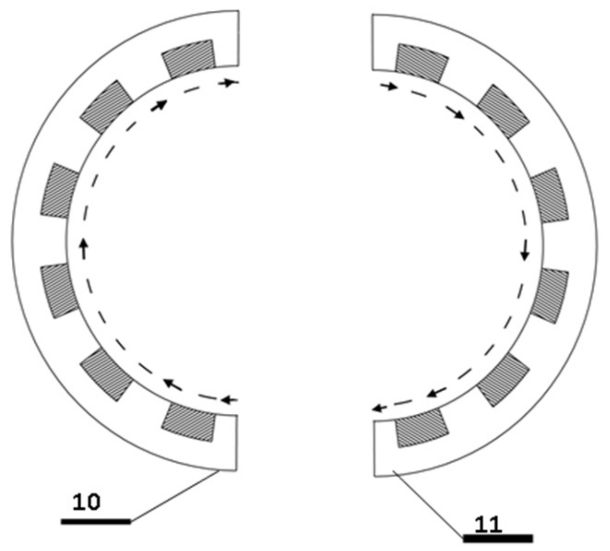
The “A” and “B” sides of the inductor are separated from each other according to Figure 5. Two pieces of the half-inductor segment with one pole pair each (2–2 poles) are thus obtained.
Step 3:
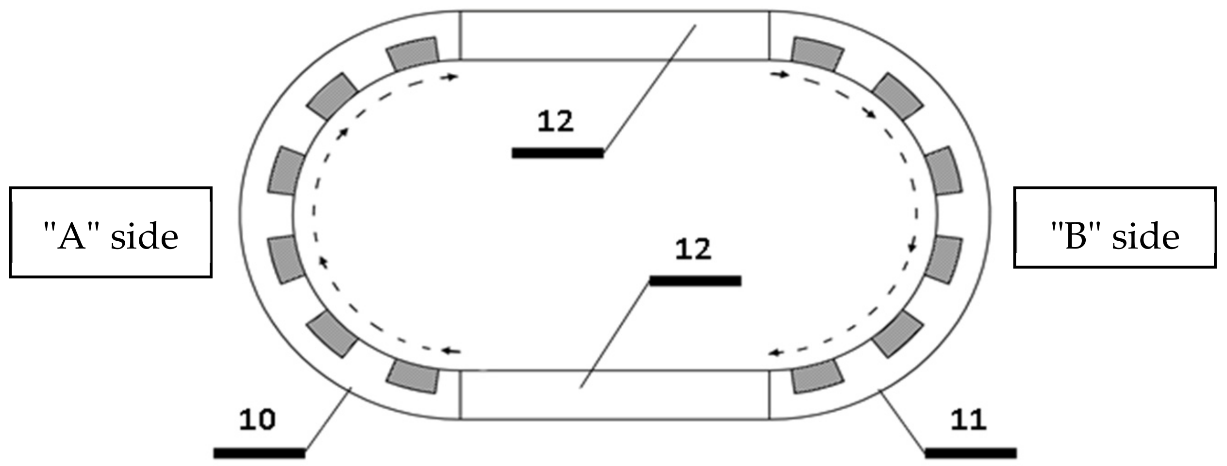
The magnetic circuit of the two half-inductors (see Figure 5, “10 and “11”) is closed by using so-called “ferromagnetic bridges” that do not contain coils, as demonstrated in Figure 6, “12”. The ferromagnetic bridges should be made of a suitable material for preventing the development of an eddy current.
Step 4:
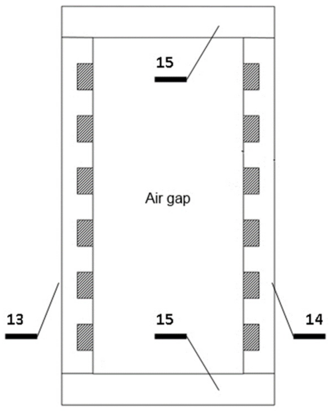
The arcuate sections of the closed inductor (see Figure 6, “10” and “11”) are converted for the plane shown in Figure 7. (Elements “10” and “11” in Figure 6 are elements in Figure 7, “13“ and ”14“. The “ferromagnetic bridges” in Figure 7 are “15” elements.)
Therefore, a traveling magnetic field moving vertically in opposite directions develops on the “A” and the “B” vertical side (see in Figure 3, Figure 10, Figure 11).
Step 5:
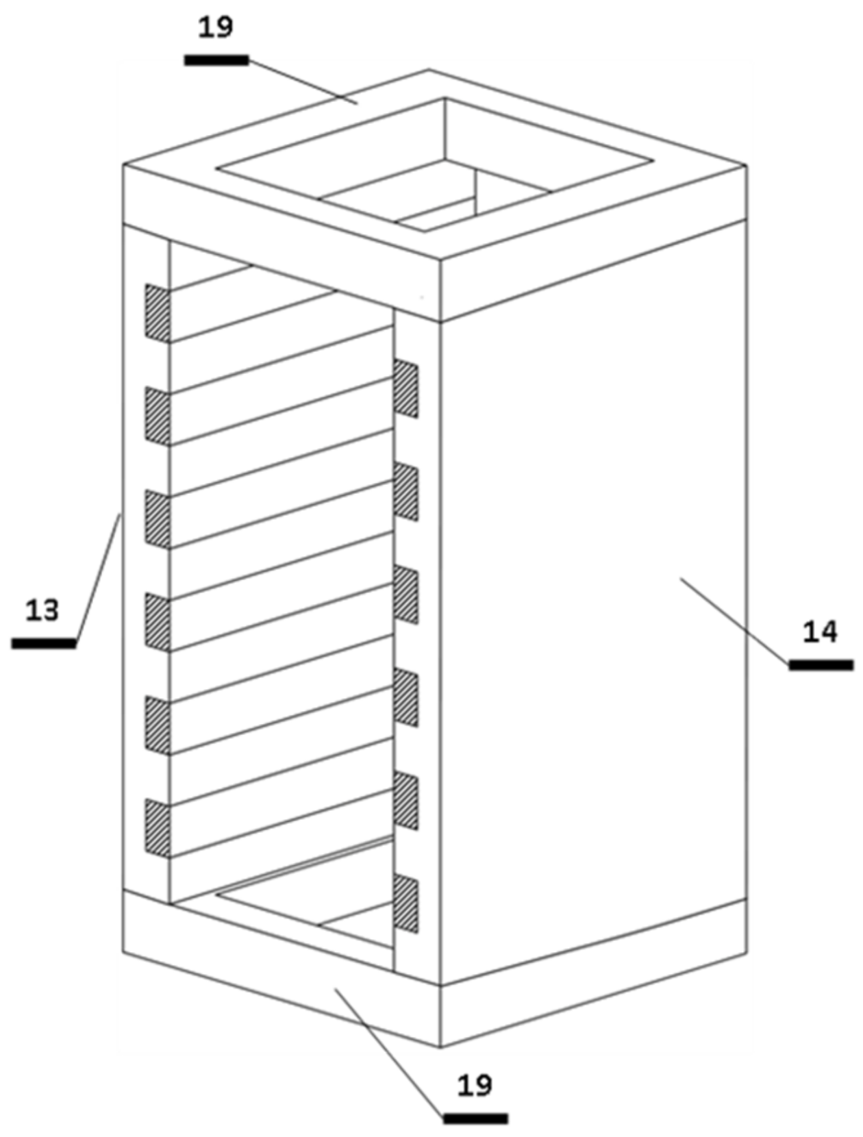
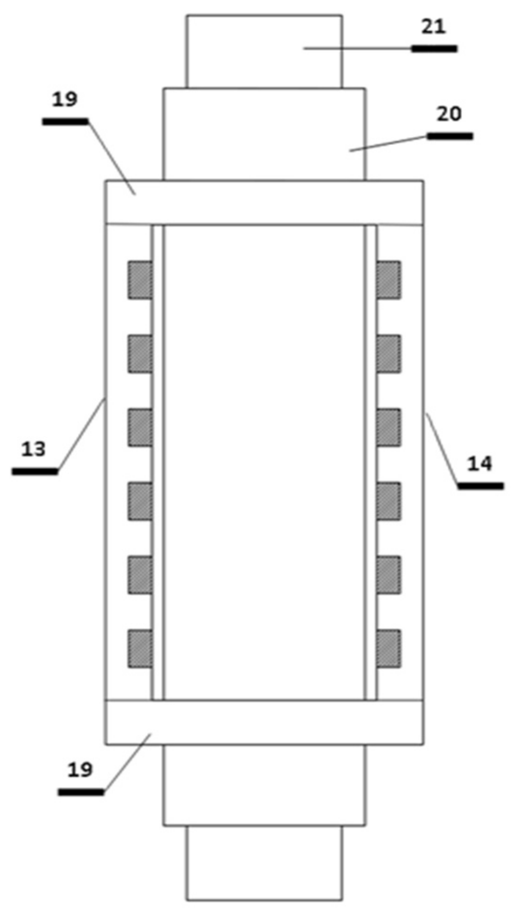
On the ferromagnetic bridges, “15”, shown in Figure 7, two mating openings are made (one on the lower and one on the upper “ferromagnetic bridge”), which creates the “19” elements shown in Figure 8. The final assembly of the TMF twin inductor shown in Figure 8 is formed.
As shown in Figure 9, the solidification channel (“21”) equipped with heating and cooling mantle (“20”) can be slipped into the openings on the ferromagnetic bridges of the TMF twin inductor seen in Figure 8.
Neither the heating–cooling mantle nor the solidification channel can contain ferromagnetic material.
This new type of solidification equipment consists of three main parts, as follows:
- (i)
- TMF twin inductor (“13”, “14”, “19”);
- (ii)
- Thermal insulation and heating–cooling mantle of solidification channel (“20”);
- (iii)
- Solidification channel (“21”).
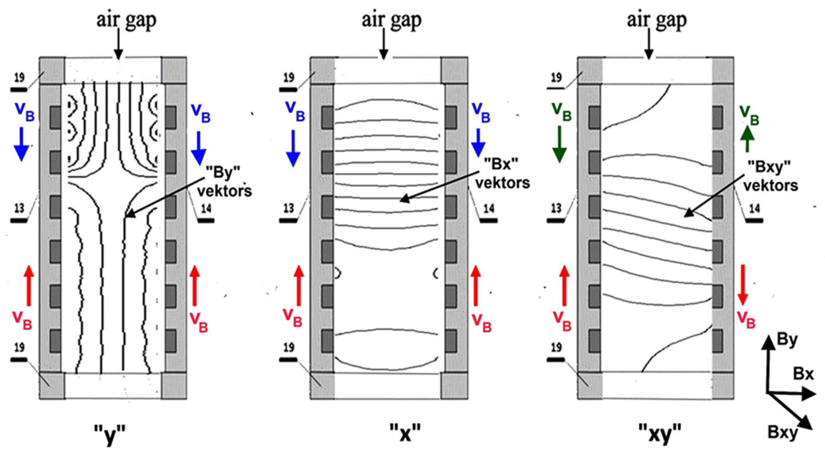
Three different magnetic fields can be produced through targeted excitation of the coils. In the case of type “x”, the magnetic induction vector (“Bx”) is perpendicular, while in the case of the “y” type, it is parallel to the wall of inductors (“By”) (Figure 10). In these cases, the magnetic field can move with vB velocity from bottom to top (upwards, red arrows) or reverse (downwards, blue arrows) on both sides. There will be movement within the melt, as shown in Figure 2a,b. The difference between the two cases is that the steering effect is stronger in the case of type “x” at a given excitation.
The third (“xy”) variation can be produced by the combination of the “x” and “y” types. The magnetic inductor vector (“Bxy”) is arbitrary between 90 and 180 degrees, and the excitation of the inductors is not the same on the two sides. As a result, the magnetic induction field will move oppositely in the two walls of the inductors. The developed melt flow can be seen in Figure 3.
At the center of the sample, the melt will move upwards on one side and downwards on the other side (red arrows) or reverse (green arrows), causing the most significant shearing stress to develop, as mentioned. The “xy” type stirring cannot be produced using the cylindrical type of inductor.
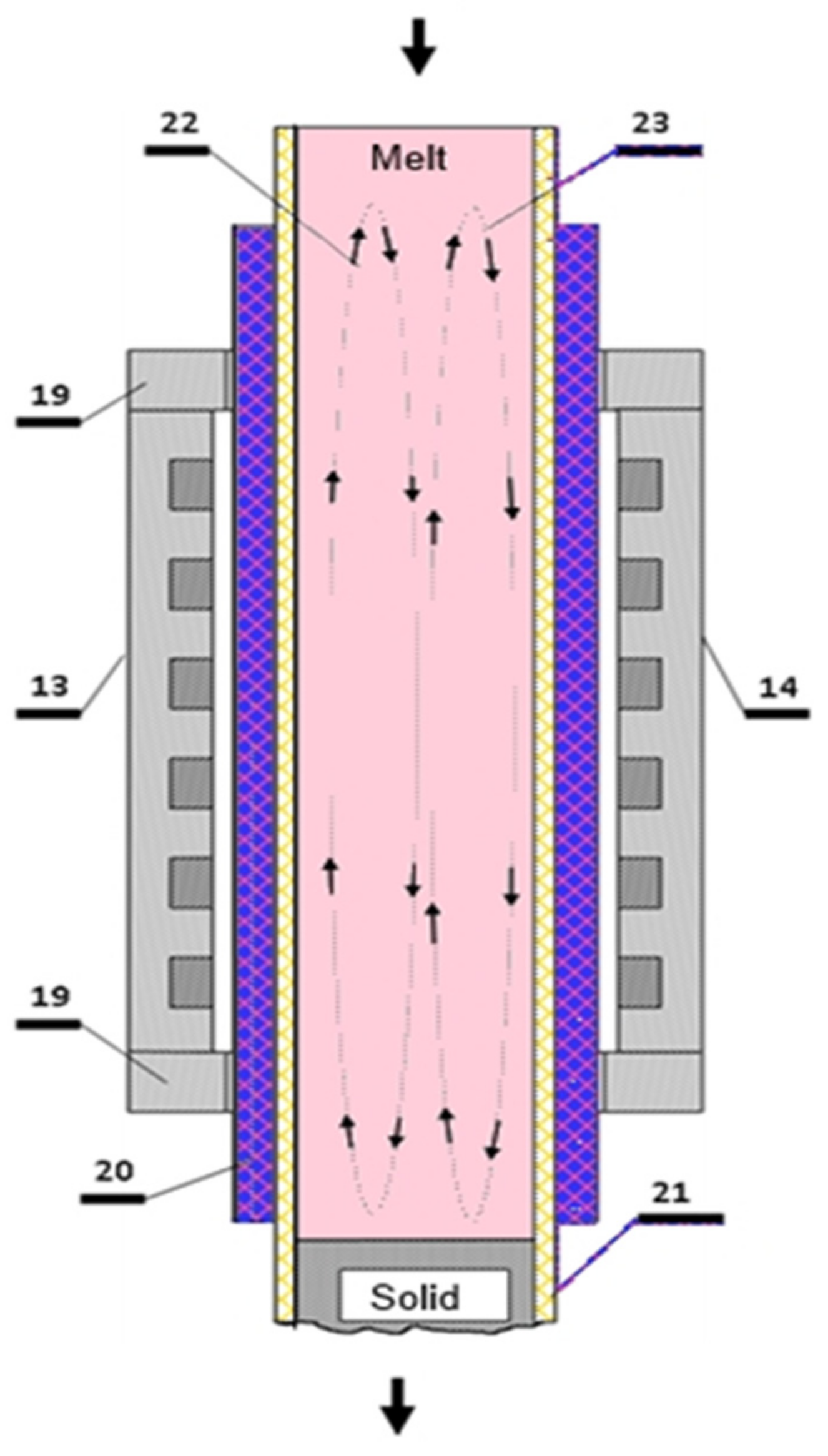
The metallic melt to be solidified can be added through the upper opening of the solidification channel (“21”), as is demonstrated in Figure 11 It starts to flow intensively under the influence of the traveling magnetic field generated by the TMF twin inductor in the solidification channel. Then, it flows through the solidification channel and will be cooled (solidified) by the heating–cooling mantle.
The aim has been to develop a method and equipment suitable for refining the solidified grain structure. This was realized using the special TMF stirrer unit described above. In the course of solidification, a strong turbulent flow and high shearing stress develop in the metallic melt in the solidification channel and in the mushy zone in such a way that some parts of the melt flow opposite to each other. The solid workpiece that exits via the lower opening has a fine grain structure.
3.2. Solidification Facility with Traveling Magnetic Field Stirrer
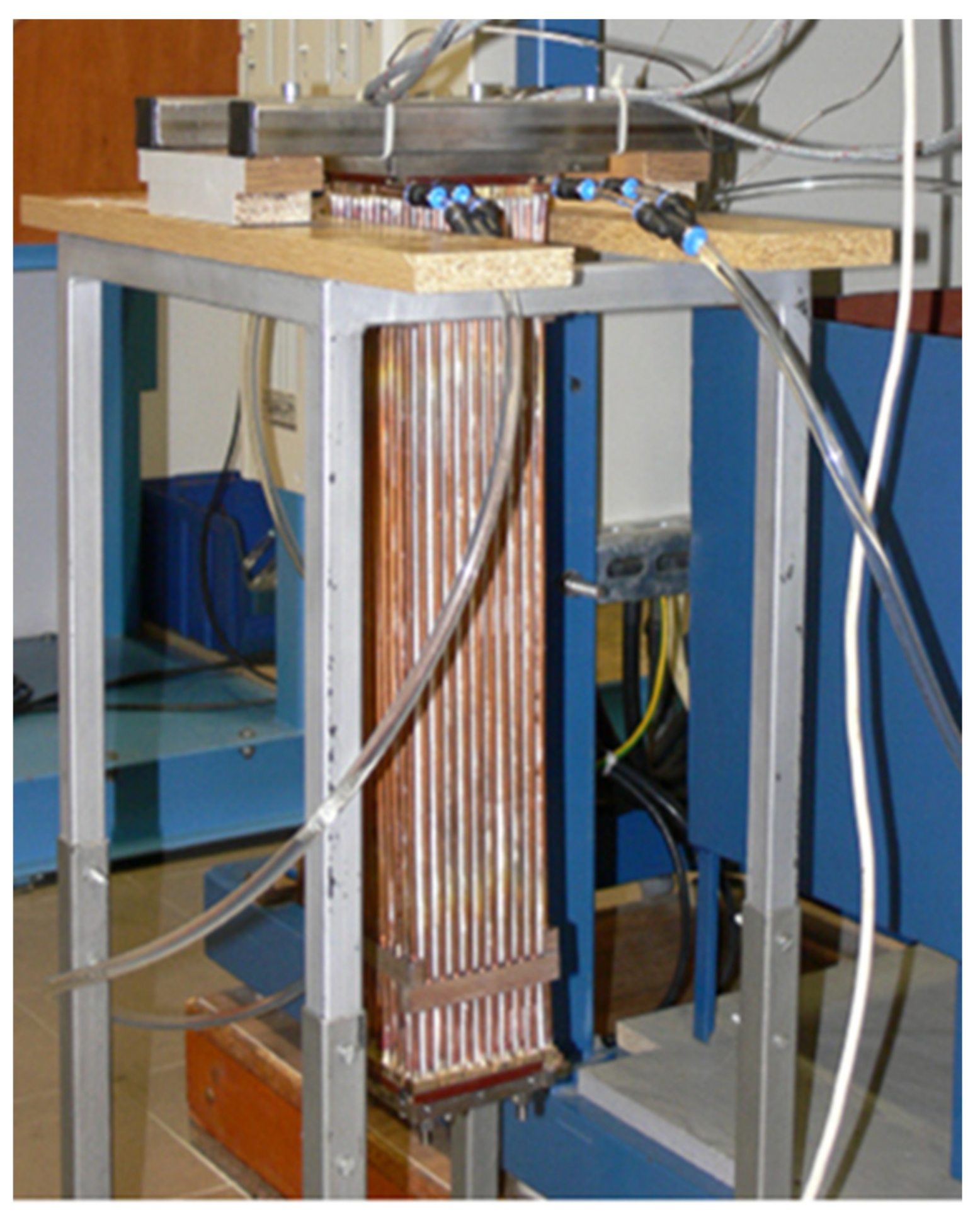
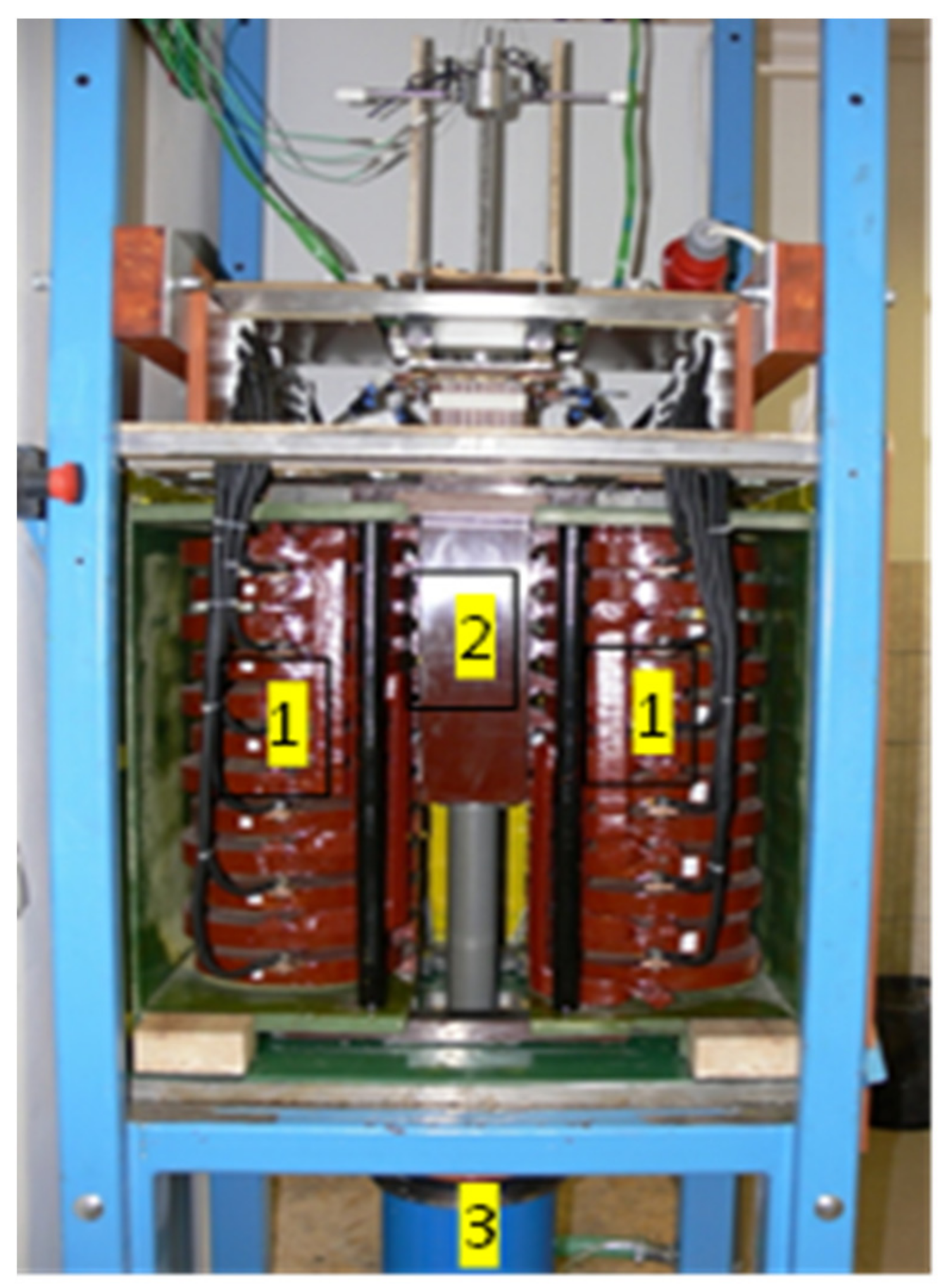
Based on the theory presented in point 4, a solidification facility was planned and built in our laboratory and operated in a vertical Bridgman-type tube furnace with four heating zones (Figure 12) and a two-pole TMF twin inductor (Figure 13). The furnace’s inner (effective) diameter is 20 mm, and its length is 200 mm. The furnace wall is cooled with water to defend the inductor from the heat. The maximum temperature of the furnace is 1000 °C, and the maximum temperature gradient is ~10 K/mm. The sample moving velocity can vary between 2 and 1000 μm/s. Under the body of the furnace is a water-cooling chamber into which the cooling core is immersed during the experiments.
The traveling magnetic field is induced with the two-pole twin inductor built parallel to the furnace (Figure 13). The maximum magnetic induction of the twin inductor and the maximum frequency were 150 mT and 75 Hz, respectively. The intensity of the magnetic field traveling in a direction parallel to the axis of the sample was constant throughout the experiment.
4. Experiments
4.1. Sample and Sample Holder
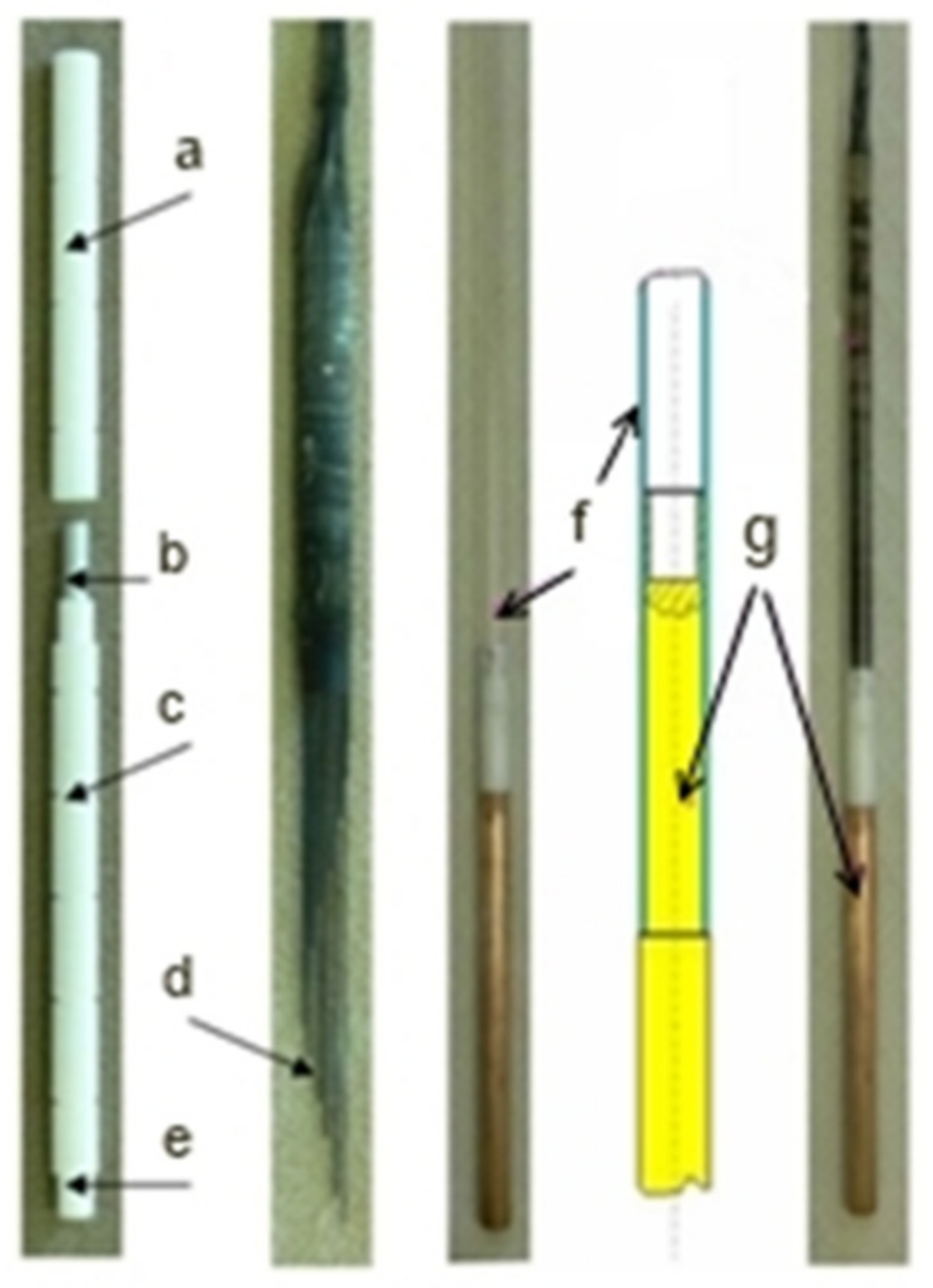
Two sample geometries were used during the experiments. The sample diameter was 8 or 20 mm, and the length was 110 or 60 mm (Figure 14). The structure of the sample holder was the same for the two types of samples. Sample (b) was inserted into an alumina capsule (a, c). The temperature distribution was measured in 13 locations by K-type thermocouples on the surface of the alumina capsules (d). The alumina capsule with thermocouples was placed in a quartz tube (f). At the bottom of the quartz tube, a cooling core from copper (g) was connected to the alumina capsule (e) to increase the unidirectional heat removal when immersed in water.
4.2. Experiment 1: The Effect of Stirring on Temperature Distribution in the Melt
As the unidirectional solidification experiments must work up a temperature difference in the melt, before the solid/liquid interface (S/L, primary dendrite tip) the temperature is increased. Due to the effect of the traveling magnetic field, the colder melt (which is near the S/L interface) and the warmer melt (which is far from the S/L interface) change places, altering the temperature distribution.
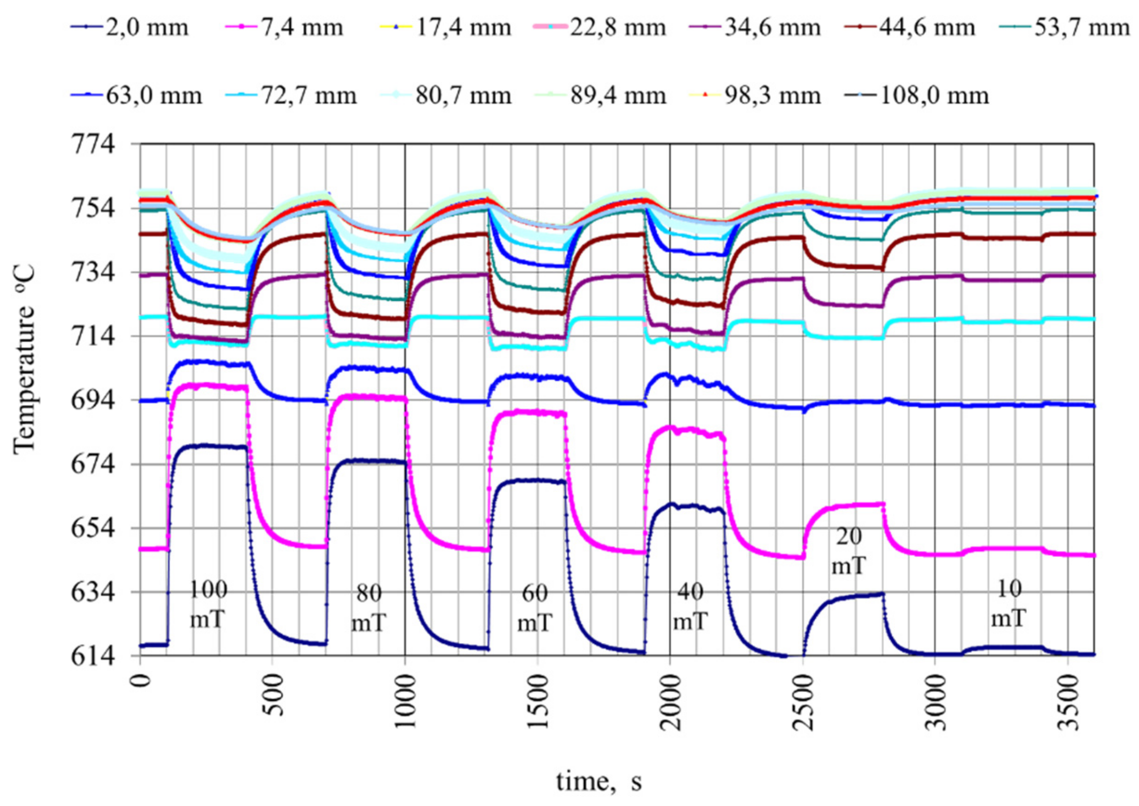
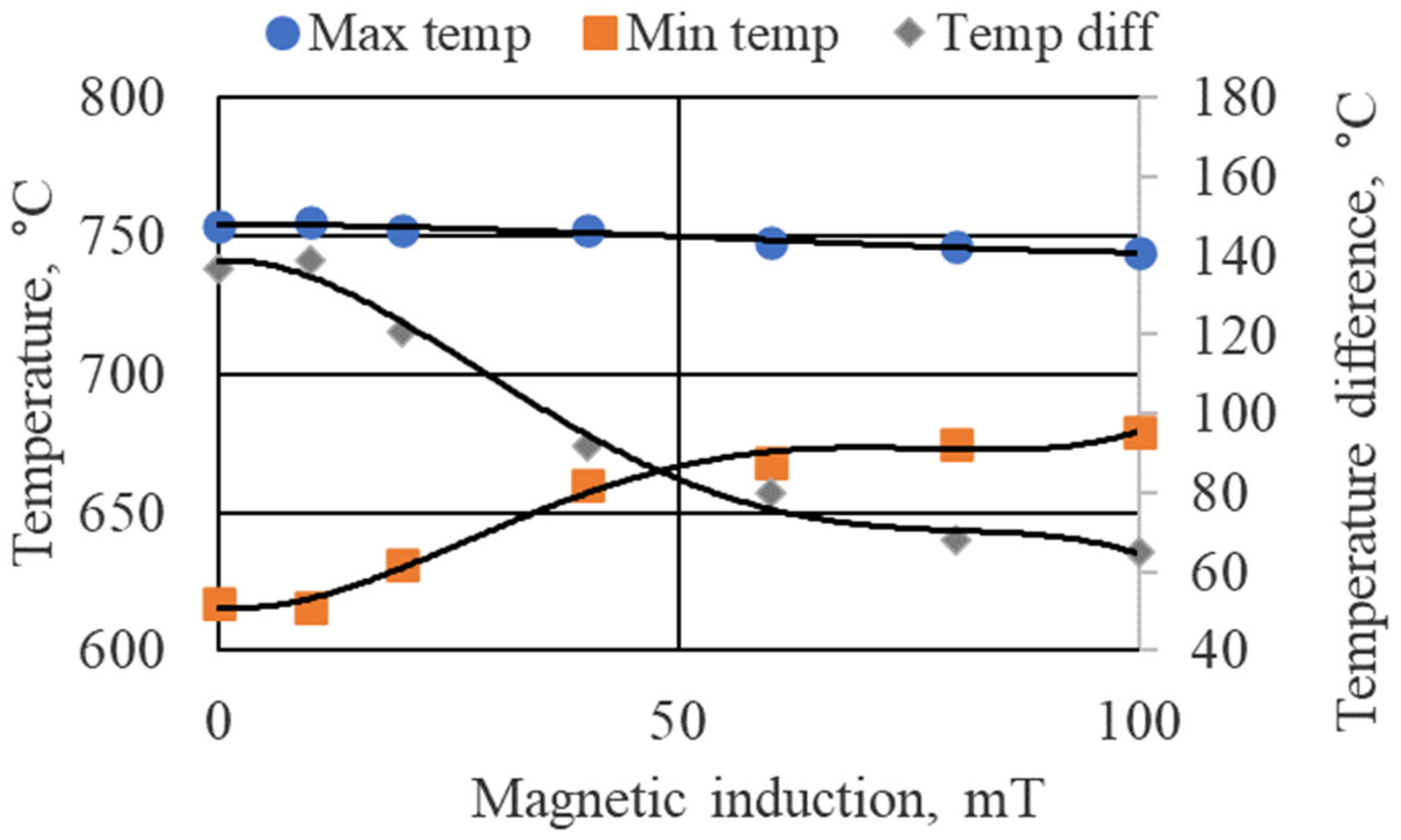
Figure 15 shows the changes in temperature distribution after switching the TMF “xy” type twin inductor on and off. The Al–7%Si sample diameter and length were 8 and 110 mm, respectively. The structure of the sample holder is in Figure 14. The liquidus temperature of the alloy was 614 °C; this was the temperature at 2 mm, and it was 750 °C at 108 mm at the start of the experiment (0 mT), such that the whole sample was practically melted. The inductor was switched on and off step by step every 300 s, changing the magnetic induction from 100 to 10 mT. As a result of the melt flow induced by the TMF, the temperature in the melt increased between 0 and ~26 mm and decreased between ~26 and 110 mm. The temperature increase and decrease values are higher, and the temperature difference in the sample is smaller with higher magnetic induction (Figure 16). This information is usable in planning experiments and simulating the melt flow.
4.3. Experiment 2: Comparison of the Effect of the Different Types of Magnetic Field on the Solidified Microstructure
4.3.1. Effect on Grain and Dendritic Structure
Unidirectional solidification experiments were performed with three different (“x”, “y”, and “xy”) types of traveling magnetic field. The material was Al–7%Si–1%Fe alloy. The dimensions of the cylindrical samples were Ø 8 mm x 110 mm, the temperature gradient (G) was 5 K/mm, and the solid/liquid interface velocity (v) was 0.05 mm/s. The synchronous velocity of the magnetic field was 29 m/s. With the first series of experiments, the effect of the different types of magnetic fields was investigated. The magnetic induction (B) was 40 mT. The magnetic field moved upwards in the case of the “x” and “y” type experiments (sample “b”, “c”), while in the case of the “xy” type experiments (samples “d”, “e”, and “f”) it moved upwards on one side and downwards on the other. With the second series of experiments, the effect of the value of the magnetic induction was investigated. In the case of the “xy” type experiments, the magnetic field was 20, 40, and 80 mT, and the other parameters of the experiments were the same as for the first series. After grinding and polishing with diamond paste, the samples were etched using a 2 V% HF water solution (Figure 17 and Figure 18) and then Barker solution (Figure 19). The dendritic and the grain structure were studied on the HF-etched and Barker-etched images, respectively.
The solidification path is as follows:
where TL = 614 °C, TBE =594 °C, and TTE = 574 °C are the liquidus, binary eutectic, and ternary eutectic temperature.
TL → TBE: liq → α
TBE → TTE: liq →α + β-Al5FeSi
TTE: α + β-Al5FeSi + Si
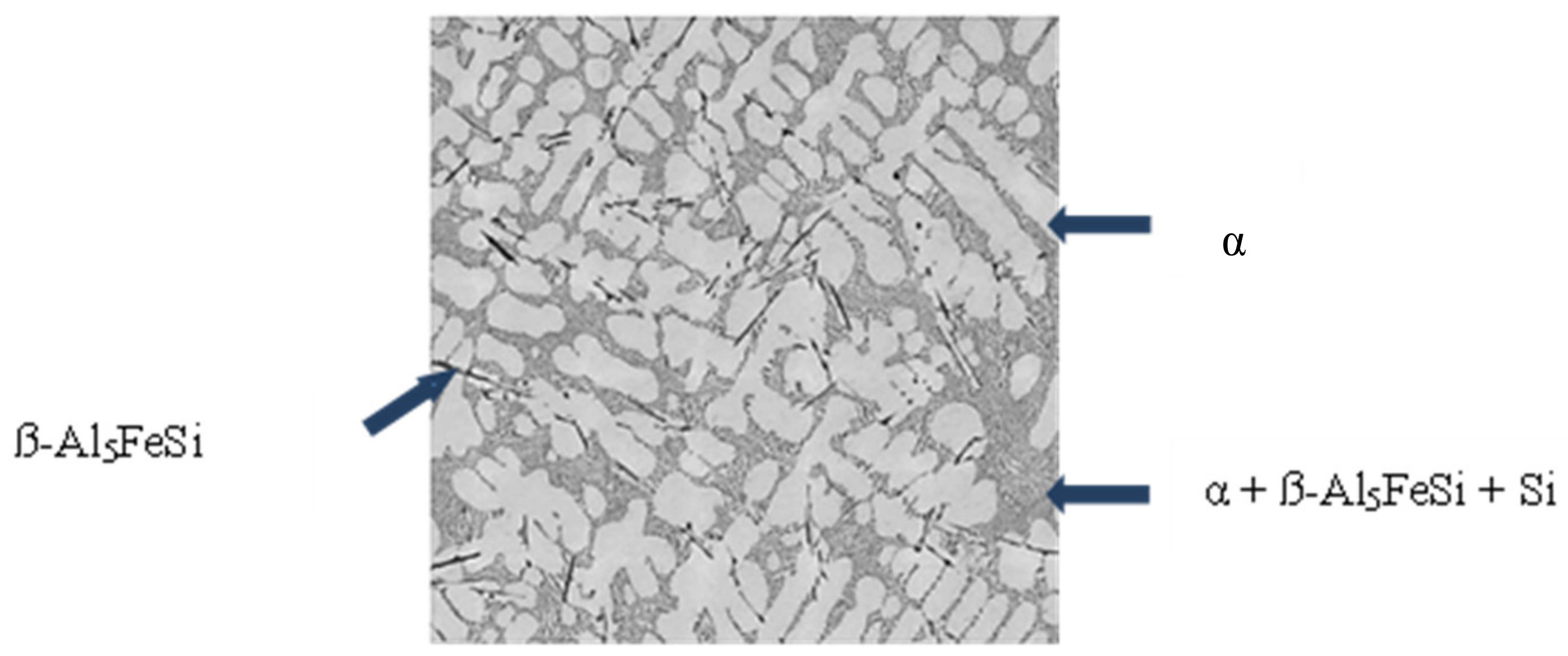
The microstructure of the alloy consisted of α aluminum solid solution dendrites and binary (α + β-Al5FeSi) and ternary (α + α-Al5FeSi + Si) eutectics. The binary eutectic degenerated and consisted of only the ß-Al5FeSi compound.
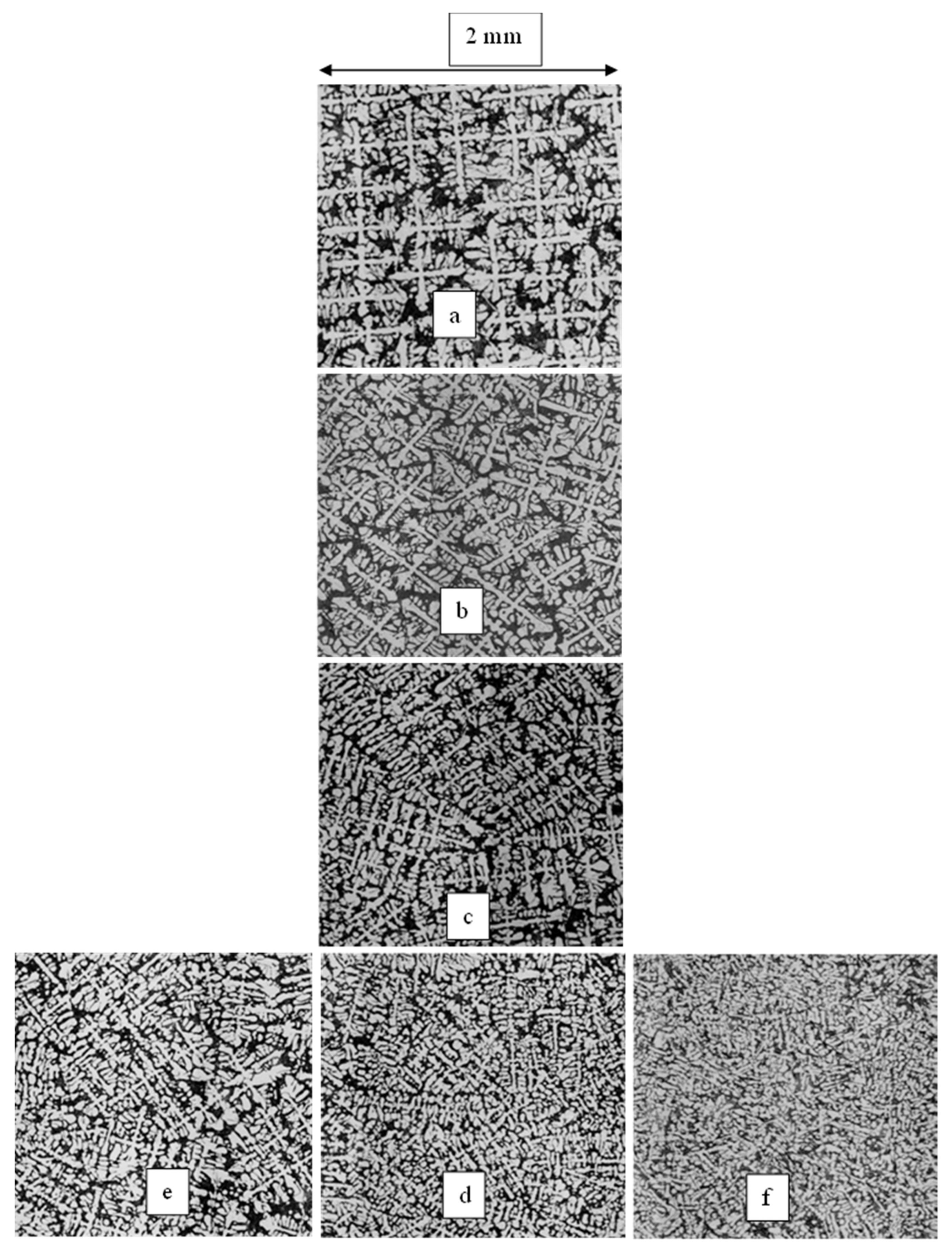
The primary dendrite arm spacing (PDAS) was measurable in the samples which have columnar structure (“a”, “b”, “c”, and “e”) (Figure 18). In the case of sample “b”, the PDAS was similar to the PDAS of “a”, which means that stirring has no effect on the PDAS. The PDAS of sample “c” is about half of the sample “a”, while for sample “e” it is between the “b” and “c”. The dendritic structure of the samples was also characterized by the specific surface of the α solid–solution dendrites S_v^α, which was measured by the circle intercept method. The dendritic microstructure is the finest in the case of “xy” stirring at a given (40 mT) magnetic induction, and it is finer with increased magnetic induction.
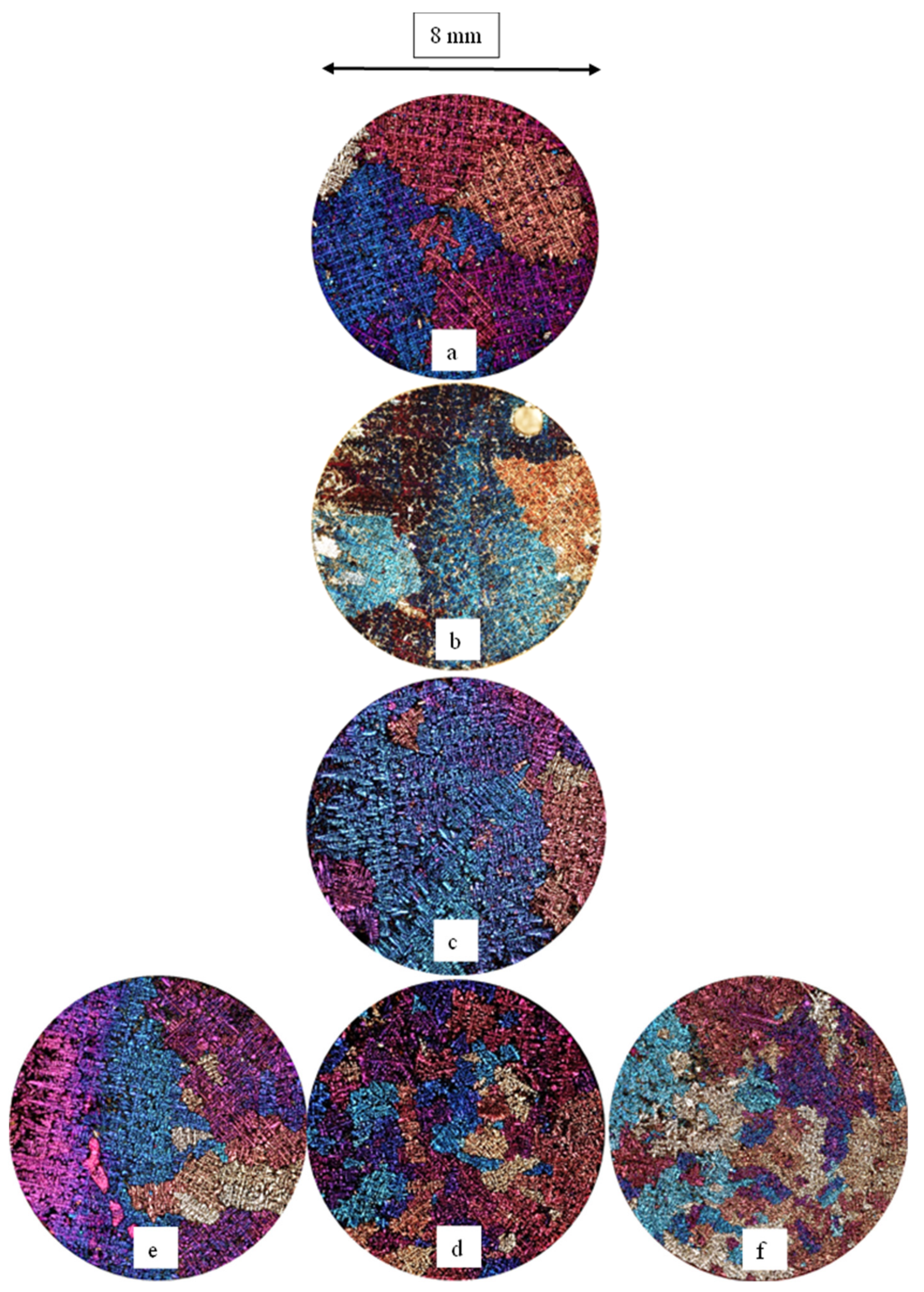
The grain structure of the samples changes with the type of magnetic field and the value of the magnetic induction (Figure 19). The magnetic induction in the case of samples “b”, “c”, and “d” was the same, 40 mT. The grains in the sample “a”, which was not stirred, are coarse columnar. The grains of sample “b” are nearly the same as those of “a”, and those of “c” are also columnar but are two times finer than those of sample “a”. The grains of sample “d” are equiaxed, and the grain number is about 10 times that of sample “a” and “b”. (See the grain number in Table 1).
With increasing magnetic induction, the grains will be more refined (samples “e”, “d”, and “f”). The grains of the sample “e” are columnar (B = 20 mT), and the grain number is similar to that of the sample “c” (B = 40 mT). This means that the effect of “xy” type stirring with 20 mT is similar to the “y” type stirring with 40 mT. The grain structure of sample “f” is 14 times more refined than sample “a”.
These experiments demonstrate that the “xy” type of stirring is more effective than the “x” or “y” types from the viewpoint of grain refinement and also dendritic structure. It must be mentioned that stirring using the TMF does not lead to macrosegregation in the center of the sample.
The grain size of the workpieces produced by this experimental equipment is finer than the grain size of a workpiece solidified without grain refinement material by almost two orders of magnitude. Notably, the finer grain size could be produced without adding any grain-refining material.
4.3.2. Effect on the Macrosegregation
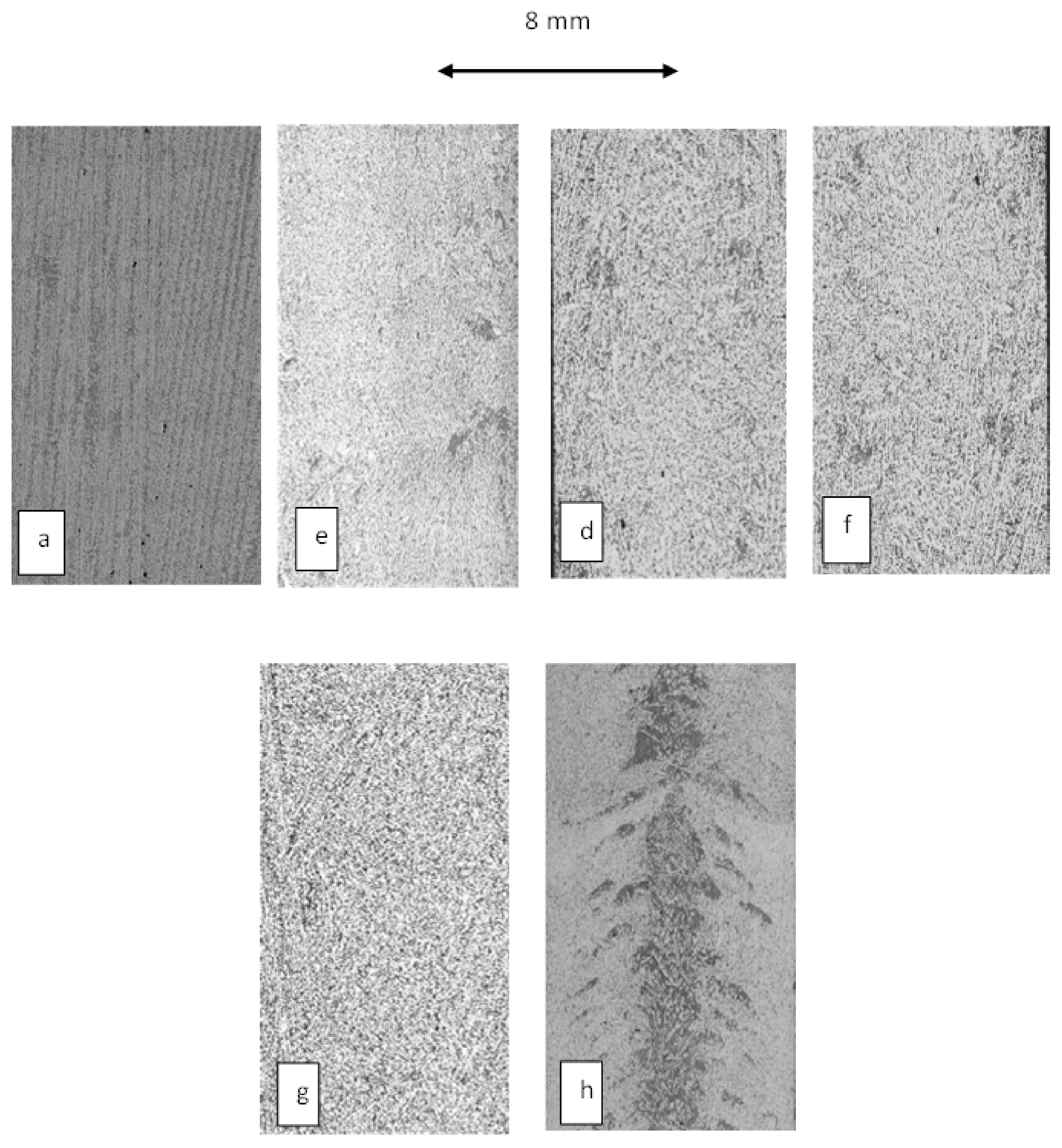
As an effect of the melt flow induced by TMF, some macrosegregation can develop. In Figure 20, the macrosegregation developed in the samples is shown in the cross-section of the a, d, e, and f samples.
The extent of the macrosegregation, which developed near two edges of the sample (black areas in the figures), increased with increasing the magnetic induction. Comparing the samples g and h, in which cases the parameters were the same, it can be clearly seen that the macrosegregation developed by the TMF stirring is much less than the macrosegregation developed by the RMF stirring. It must be mentioned that stirring using the TMF does not lead to macrosegregation in the center of the sample. Moreover, comparing the samples f and g, in which cases B and G are the same, and the v is higher in the case of sample f, it can be stated that if the solid/liquid interface velocity increases, the extent of the macrosegregation decreases; finally, it can eliminate it.
By periodically changing the direction of movement of the magnetic field of the TMF twin inductor, the macrosegregation at the edge of the sample can be eliminated. With our TMF twin inductor, the direction of travel of the magnetic field can be reversed up to once per second.
4.4. Experiment 3: Effect on the Columnar/Equiaxed Transition (CET)
The Al–10%Si–0.2%Fe alloy was solidified by stirring using the new TMF stirrer (Figure 21). The temperature gradient, the solid/liquid interface velocity, and the cooling rate were 5 K/mm, 0.2 mm/s, and 1.0 K/s, respectively. The part “a” of the sample was not stirred, and the “b” part was stirred at 110 mT with the frequency set to 50 Hz. The sample diameter and the length were 8 and 100 mm, respectively. After solidification, two cross-sections were cut from the sample near where the TMF was switched on, and then, the part between the two cross-sections was cut parallel to the sample axis. The cross and the longitudinal sections were ground and polished using diamond paste and etched with Barker solution.
The solidification path is the same as in the case of Experiment 2, but the TL and TBE are less, 590 °C and 578 °C, respectively.
After switching the TMF, there an immediate change from fine columnar (Figure 21a) to a finer, equiaxed microstructure (Figure 21b). The grain number as measured on the cross-sections is 16 for the columnar part and 96 for the equiaxed part. The stirred part does not exhibit any macrosegregation. This experiment demonstrates that the new type of TMF stirring is suitable for eliminating the columnar microstructure that develops in the workpieces near the wall of the mold and results in the production of a very fine equiaxed microstructure without macrosegregation.
5. Summary and Conclusions
In the case of some industrial cast technology (e.g., steel, copper, and nickel alloys), it is impossible to refine the solidified grain structure (i.e., change the structure from columnar to equiaxed) because no effective grain refinement material has been found. The refining can thus be carried out by stirring the melt, which results in a flowing melt that causes the breakage of some small particles from the solid phase (from the growing dendrite), producing heterogeneous nucleation. A practical method for stirring is to use a traveling magnetic field. In this paper, we show a new type of TMF inductor, through which, in the course of solidification, a strong turbulent flow and high shearing stress develop in the metallic melt, coexisting in the solidification channel and mushy zone in such a way that some parts of the melt flow opposite to each other. Based on this method, a solidification facility was planned and built. Using this facility, three experiments were performed to demonstrate the application of this method.
The first experiment showed that the induction of the magnetic field caused a change in the temperature distribution in the melt. Due to the effect of the TMF stirring, the temperature of the higher temperature part of the sample decreased, while the temperature of the lower temperature part increased. This causes the temperature difference in the sample to be reduced with higher magnetic induction.
The second experiment demonstrated that the so-called “xy” type of magnetic field (when the magnetic induction field moves oppositely in the two walls of the inductors, developing the most significant shearing stress) was most effective and produced the finest grain and dendritic structure, which become finer as magnetic induction increases. Stirring the melt with the TMF does not lead to the same extent of macrosegregation in the sample, in contrast to the RMF stirring. In addition, by increasing the solid/liquid interface velocity, the extent of the macrosegregation decreases.
With our TMF twin inductor, the direction of travel of the magnetic field can be reversed up to once per second with which the remained macrosegregation can be eliminated.
By the third experiment, it was shown that after switching on the TMF, there was an immediate change from a fine columnar to a finer, equiaxed microstructure. This experiment demonstrates that the new type of TMF stirring is suitable for eliminating the columnar microstructure that develops in the workpieces near the wall of the mold, resulting in the production of a very fine, equiaxed microstructure without macrosegregation.
6. Patent
Hungarian patent: Eljárás és berendezés kristályosodás során kialakuló szemcseszerkezet finomítására/Method and equipment for refinement of solidified grain structure. Patent number: HU 231169.
Author Contributions
Conceptualization: A.R. (András Roósz) and A.R. (Arnold Rónaföldi); methodology: A.R. (András Roósz) and A.R. (Arnold Rónaföldi); hardware: A.R. (Arnold Rónaföldi); investigation: M.S. and Z.V.; writing—original draft preparation, A.R. (András Roósz); writing—review and editing: Z.V. and M.S.; project administration, Z.V. All authors have read and agreed to the published version of the manuscript.
Funding
The present work was financially supported by the project entitled “Formation of as-solidified structure and macrosegregation during unidirectional solidification under controlled flow conditions” of the National Research Development and Investigation Office (No. 130946).
Institutional Review Board Statement
Not applicable.
Informed Consent Statement
Not applicable.
Data Availability Statement
Data may be requested from the corresponding authors.
Conflicts of Interest
The authors declare no conflict of interest.
References
- Sigworth, G.K.; Kuhn, T.A. Grain Refinement of Aluminium Casting Alloys; AFS Transactions; American Foundry Society: Schaumburg, IL, USA, 2007; pp. 1–12. [Google Scholar]
- Easton, M.; Davidson, C.; St John, D. Grain Morphology of As-Cast Wrought Aluminium Alloys. In Proceedings of the 12th International Conference on Aluminium Alloys, Yokohama, Japan, 5–9 September 2010; pp. 173–178. [Google Scholar]
- Kori, S.A.; Murty, B.S.; Chakraborty, M. Development of an Efficient Grain Refiner for Al-7Si Alloy Mater. Sci. Eng. A 2000, 280, 58–61. [Google Scholar] [CrossRef]
- Li, H.T.; Xia, M.; Jarry, P.; Scamans, G.M.; Fan, Z. Grain Refinement in a AlZnMgCuTi Alloy by Intesive Melt Shearing: A Multi-step Nucleation Mechanism. J. Cryst. Growth 2011, 314, 285–292. [Google Scholar] [CrossRef] [Green Version]
- Zimmermann, G.; Sturz, L.; Walterfang, M.; Dagner, J. Effect of Melt Flow on Dendrites Growth in AlSi7-Based Alloy During Directional Solidification. Int. J. Cast Met. Res. 2009, 22, 335–338. [Google Scholar] [CrossRef]
- Zimmermann, G.; Vitusevych, W.T.; Sturz, L. Microsturcture Formation in AlSi6Cu4 Alloy with Forced Melt Flow Induced by a Rotating Magnetic Field, Mater. Sci. Forum 2010, 649, 249–254. [Google Scholar] [CrossRef]
- Nikrityuk, P.A.; Eckert, K.; Grundmann, R. A Numerical Study of Unidirectional Solidification of a Binary Metal Alloy under Influence of a Rotating Magnetic Field. Int. J. Heat Mass Transf. 2006, 49, 1501–1515. [Google Scholar] [CrossRef]
- Eckert, S.; Nikrityuk, P.A.; Räbiger, D.; Eckert, K.; Gerbeth, G. Efficient Melt Stirring Using Pulse Sequences of a Rotating Magnetic Field. Metall. Mater. Trans. 2007, 39B, 374–386. [Google Scholar]
- Veres, Z.; Roósz, A.; Rónaföldi, A.; Sycheva, A.; Svéda, M. The Effect of Melt Flow Induced by RMF on the Meso- and Micro-Structure of Unidirectionally Solidified Al–7wt.% Si alloy Benchmark Experiment Under Magnetic Stirring. J. Mater. Sci. Technol. 2022, 103, 197–208. [Google Scholar] [CrossRef]
- Zaidat, K.; Ouled-Khachroum, T.; Vian, G.; Garnier, C.; Mangelinck-Noe, N.; Dupouya, M.D.; Moreau, R. Directional Solidification of Refined A1–3.5wt% Ni Under Natural Convection and Under a Forced Flow Driven by a Travelling Magnetic Field. J. Cryst. Growth 2005, 275, e1501–e1505. [Google Scholar] [CrossRef]
- Su, Y.-Q.; Xu, Y.-J.; Zhao, L.; Guo, J.-J.; Fu, H.-Z. Effect of Electromagnetic Force on Melt Induced by Travelling Magnetic Field. Trans. Nonferrous Met. Soc. China 2010, 20, 662–667. [Google Scholar] [CrossRef]
- Zou, Q.C.; Jie, J.C.; Liu, S.C.; Wang, T.M.; Yin, G.M.; Li, T.J. Effect of Travelling Magnetic Field on Separation and Purification of Si from Al-Si Melt During Solidification. J. Cryst. Growth 2015, 42, 68–73. [Google Scholar] [CrossRef]
- Qin, L.; Shen, J.; Feng, Z.; Shang, Z.; Fu, H. Microstructure Evolution in Directionally Solidified Fe-Ni Alloys Under Travelling Magnetic Field. Mater. Lett. 2014, 115, 155–158. [Google Scholar] [CrossRef]
- Min, Z.; Shen, J.; Feng, Z.; Wang, L.; Wang, L.; Fu, H. Effects on Melt Flow on the Primary Dendrites Pacing of Pb-Sn Binary Alloy During Directional Solidification. J. Cryst. Growth 2011, 320, 41–45. [Google Scholar] [CrossRef]
- Leyuan, Q.; Qiulin, L.; Wei, L. Modelling and Experiments on Electromagnetic Separation of Inclusions from Aluminum Melt under Combined Magnetic Field. Rare Met. Mat. Eng. 2014, 43, 8. [Google Scholar]
- Yanjie, H.; Li, Q.; Liu, W. Effect of Combined Magnetic Field on the Eliminating Inclusions from Liquid Aluminum Alloy. Mater. Lett. 2011, 65, 1226–1228. [Google Scholar]
- Rónaföldi, A.; Roósz, A. Method and Equipment for Refinement of Solidified Grain Structure. H.U. Patent 2,311,69, 19 May 1970. [Google Scholar]
Figure 1.
Melt flow developed by the RMF inductors. 1: primary flow, 2: secondary flow.

Figure 2.
Melt flow developed using traditional TMF inductors, The magnetic field moves from upwards (a) to downwards (b). 3 and 4: melt flow direction.
Figure 2.
Melt flow developed using traditional TMF inductors, The magnetic field moves from upwards (a) to downwards (b). 3 and 4: melt flow direction.

Figure 3.
Flow images developed by the TMF twin inductor.

Figure 4.
Front view of the four-pole RMF inductor developing the rotating magnetic field “6”, “7”: exciting coils, “8”: closed iron core, “9”: moving direction of rotating magnetic field.
Figure 4.
Front view of the four-pole RMF inductor developing the rotating magnetic field “6”, “7”: exciting coils, “8”: closed iron core, “9”: moving direction of rotating magnetic field.

Figure 5.
Front view of the “half” inductor-pairs with an open magnetic circuit; it was developed after separating the pole pairs, being on the ”A” (“10”) and ”B” (“11”) side from each other.
Figure 5.
Front view of the “half” inductor-pairs with an open magnetic circuit; it was developed after separating the pole pairs, being on the ”A” (“10”) and ”B” (“11”) side from each other.

Figure 6.
Front view of an arched inductor without demonstrating the coil heads. The inductor is of a closed magnetic circuit constructed by connecting the magnetic circuit of the “half” inductor pair (by closing the magnetic circuit) using ferromagnetic bridges (“12”).
Figure 6.
Front view of an arched inductor without demonstrating the coil heads. The inductor is of a closed magnetic circuit constructed by connecting the magnetic circuit of the “half” inductor pair (by closing the magnetic circuit) using ferromagnetic bridges (“12”).

Figure 7.
Front view of the converted version of TMF twin inductor seen in Figure 6 with a closed magnetic circuit. This inductor was constructed by changing the arched inductor sections (by converting them into plane ones, “13” and “14”) without representing the coil heads.
Figure 7.
Front view of the converted version of TMF twin inductor seen in Figure 6 with a closed magnetic circuit. This inductor was constructed by changing the arched inductor sections (by converting them into plane ones, “13” and “14”) without representing the coil heads.

Figure 8.
Axonometric image of TMF twin inductor constructed completely (with inlets formed in the ferromagnetic bridges ”19”, in which the solidification channel ”21”will be placed) without demonstrating the coil heads.
Figure 8.
Axonometric image of TMF twin inductor constructed completely (with inlets formed in the ferromagnetic bridges ”19”, in which the solidification channel ”21”will be placed) without demonstrating the coil heads.

Figure 9.
The solidification channel (“21”) equipped with a heating and cooling mantle (“20”).

Figure 10.
The different types of magnetic field.

Figure 11.
The image of melt flow developed by the TMF twin inductor during the solidification process in the longitudinal section of solidification unit. “22”: direction of melt flow produced by “A” side of inductor. “23”: direction of melt flow produced by “B” side of inductor.
Figure 11.
The image of melt flow developed by the TMF twin inductor during the solidification process in the longitudinal section of solidification unit. “22”: direction of melt flow produced by “A” side of inductor. “23”: direction of melt flow produced by “B” side of inductor.

Figure 12.
Bridgman-type tube furnace with 4 heating zones.

Figure 13.
2-pole TMF inductor (1) with the furnace (2) and the water tank (3).

Figure 14.
Sample and sample holder where (a) and (c) are the upper and lower alumina capsule, (b) is the sample, (d) is the thermocouples, (e) is the connection part of the lower alumina capsule to the copper cooling core (g), and (f) is the quartz tube.
Figure 14.
Sample and sample holder where (a) and (c) are the upper and lower alumina capsule, (b) is the sample, (d) is the thermocouples, (e) is the connection part of the lower alumina capsule to the copper cooling core (g), and (f) is the quartz tube.

Figure 15.
The temperature distribution in the melt at different strengths of magnetic induction over time.
Figure 15.
The temperature distribution in the melt at different strengths of magnetic induction over time.

Figure 16.
The maximum and minimum temperature and the temperature difference vs. magnetic induction strength.
Figure 16.
The maximum and minimum temperature and the temperature difference vs. magnetic induction strength.

Figure 17.
Microstructure of the Al–7%Si–1%Fe alloy.

Figure 18.
Dendritic structure of unidirectional solidification of the Al–7%Si–1%Fe alloy. Etching with 2 V% HF water solution. Temperature gradient (G): 5 K/mm, solid/liquid front velocity (v): 0.05 mm/s. (a) B = 0 mT, (b) B = 40 mT, “x” type, (c) B = 40 mT, “y type”, (d) B= 40 mT, “xy” type, (e) B = 20 mT, “xy” type, and (f) B = 80 mT, “xy” type.

Figure 19.
Grain structure of unidirectional solidification of the Al–7%Si–1%Fe alloy. Etching with Barker solution. Temperature gradient (G): 5 K/mm, solid/liquid front velocity (v): 0.05 mm/s. (a) B = 0 mT, (b) B = 40 mT, “x” type, (c) B = 40 mT, “y” type, (d) B= 40 mT, “xy” type, (e) B = 20 mT, “xy” type, and (f) B = 80 mT, “xy” type.

Figure 20.
Macrosegregation in unidirectional solidification of the Al–7%Si–1%Fe alloy. Etching with 2 V% HF water solution. Temperature gradient (G): 5 K/mm, solid/liquid front velocity (v): 0.05 mm/s, “xy” type. (a) B = 0 mT, (e) B = 20 mT, (d) B= 40 mT, (f) B = 80 mT, temperature gradient (G): 5 K/mm, solid/liquid front velocity (v): 0.2 mm/s, (g) B = 80 mT, “xy” type, and (h) stirring by RMF (B = 80 mT).

Figure 21.
Columnar/equiaxed transition (CET). Longitudinal (a) and cross-sections (b).


Table 1.
Parameters of Experiment 2 and the grain and dendritic structure.
| Sample | Type | Magnetic Induction B, mT | Type of Grains | Grain Number on the Cross Section | Average Area of Grains mm2 | Average Diameter mm | PDAS µm | Specific Surface of α Phase mm2/mm3 |
|---|---|---|---|---|---|---|---|---|
| a | No stirring | 0 | Columnar | 11.00 | 2.28 | 0.85 | 449 | 126 |
| b | “x” | 40 | Columnar | 10.00 | 2.51 | 0.89 | 438 | 132 |
| c | “y” | 40 | Columnar | 20.00 | 1.26 | 0.63 | 269 | 158 |
| d | “xy” | 40 | Equiaxed | 94.00 | 0.27 | 0.29 | - | 251 |
| e | “xy” | 20 | Columnar | 24.00 | 1.05 | 0.58 | 366 | 163 |
| f | “xy” | 80 | Equiaxed | 140.00 | 0.18 | 0.24 | - | 206 |
Publisher’s Note: MDPI stays neutral with regard to jurisdictional claims in published maps and institutional affiliations. |
© 2022 by the authors. Licensee MDPI, Basel, Switzerland. This article is an open access article distributed under the terms and conditions of the Creative Commons Attribution (CC BY) license (https://creativecommons.org/licenses/by/4.0/).
Share and Cite
MDPI and ACS Style
Rónaföldi, A.; Veres, Z.; Svéda, M.; Roósz, A. New Equipment and Method for Refining the Solidified Grain Structure. Metals 2022, 12, 658. https://doi.org/10.3390/met12040658
AMA Style
Rónaföldi A, Veres Z, Svéda M, Roósz A. New Equipment and Method for Refining the Solidified Grain Structure. Metals. 2022; 12(4):658. https://doi.org/10.3390/met12040658
Chicago/Turabian StyleRónaföldi, Arnold, Zsolt Veres, Mária Svéda, and András Roósz. 2022. "New Equipment and Method for Refining the Solidified Grain Structure" Metals 12, no. 4: 658. https://doi.org/10.3390/met12040658
Note that from the first issue of 2016, this journal uses article numbers instead of page numbers. See further details here.