
Corrosion Protection of ZK60 Wrought Magnesium Alloys by Micro-Arc Oxidation
by
 ,
,
Yuna Xue
1,*, 
Xin Pang
2,*,
Seyyed Mohamad Hasan Karparvarfard
3,
Hamid Jahed
3,
Sheji Luo
1 and
Yi Shen
1 1
School of Materials Science and Engineering, Xi’an Shiyou University, Xi’an 710065, China
2
CanmetMATERIALS, Energy Technology Sector (ETS), Natural Resources Canada, Hamilton, ON L8P 0A5, Canada
3
Fatigue and Stress Analysis Laboratory, Department of Mechanical and Mechatronics Engineering, University of Waterloo, Waterloo, ON N2L 3G1, Canada
*
Authors to whom correspondence should be addressed.
Metals 2022, 12(3), 449; https://doi.org/10.3390/met12030449
Submission received: 2 February 2022
/
Revised: 26 February 2022
/
Accepted: 2 March 2022
/
Published: 4 March 2022
(This article belongs to the Special Issue Advances and Improvement in Corrosion-Fatigue Resistance of Magnesium Alloy)
Abstract
:The influences of the forging process and micro-arc oxidation (MAO) coating on the corrosion behavior of ZK60 wrought magnesium alloys exposed to salt spray and constant stress corrosion conditions were investigated. The microstructure of the ZK60 Mg alloy specimens forged under different temperatures (i.e., 250, 300, and 450 °C) was characterized using metallography, EBSD, and SEM. It was demonstrated that the ZK60 alloy forged at 300 °C (i.e., ZK60EF-300) had finer grain and uniformly distributed β-phase and, thus, better corrosion resistance than the ZK60 forged at 450 °C. At the lower forging temperature (250 °C) twins formed in the ZK60 alloy, which accelerated the corrosion of the ZK60E-250 specimen. The MAO coating provided robust corrosion protection for all the ZK60 wrought Mg alloy substrates. The salt spray corrosion test results showed that when the MAO coating broke down at certain weak sites, the corrosion performance of the coated Mg alloy was predominantly determined by the alloy substrate. The stress corrosion behaviors of the uncoated and MAO-coated ZK60 alloy specimens were also investigated under a constant load of 80 MPa in 3.5 wt.% NaCl solution. The MAO coating was found to improve the stress-corrosion resistance of the ZK60 alloy pronouncedly.
1. Introduction
For the past quarter-century, automotive manufacturers are facing huge challenges in reducing vehicle weight to meet governments’ ever-increasing requirements on fuel efficiency and greenhouse gas emissions [1]. Magnesium and magnesium alloys, owing to their low density and favorable mechanical properties, have attracted considerable attention for lightweight applications [2]. Recently, magnesium alloys are not only being utilized for manufacturing internal parts in automotive, but are also being considered for external components, such as the lower control arm of the front suspension. These components are unavoidably subjected to both mechanical loading and environmental corrosion [3,4]. The average stress level that the lower control arms are subjected to is about 50 MPa [5]. The maximum stress of the car wheel under the constant load is about 75 MPa [6]. According to Winzer et al. [7], when the applied stress is above 50% of the yield stress of Mg alloys, stress corrosion cracking might occur in a service–corrosion environment. To date, most magnesium alloy components are fabricated by die-casting. Wrought magnesium alloys are known for higher strength and better ductility than cast alloys [8,9,10,11]. Nevertheless, the high tendency to corrosion and stress corrosion of wrought magnesium alloys when in contact with water, salt, or other corrosive media has become a major obstacle to their widespread adoption in the automotive industry [12,13]. Many published research works have focused on the mechanical performances, including tension–compression properties and fatigue behavior of cast, extruded, rolled, or forged wrought magnesium alloys [13,14,15,16,17]. A lot of them studied the deformation behavior of Mg alloys under different temperatures [17,18]. Only limited research looked into the corrosion behavior of wrought Mg alloys [19]. Recently, the static corrosion and stress corrosion behaviors of magnesium alloys in various service environments have gained increasing attention [20,21,22]. Further investigations are needed to better understand the effects of the forging process on the corrosion and stress corrosion performances of wrought magnesium alloys, in order to expand their utilization for automotive structural components.
The objective of this work is to identify advanced material processing technologies for the manufacturing of the next-generation suspension components in passenger vehicles with improved static and stress corrosion resistance, by studying an emerging surface protection technology known as micro-arc oxidation (MAO).
Surface coating is an economical and effective method for the corrosion protection of magnesium alloys. MAO is a coating technology that enables the formation of thick ceramic surface coatings on magnesium alloys. Several numerical modeling studies on corrosion mechanism of coatings have been carried out to help understand coating corrosion performance [23,24,25]. MAO coatings have been reported to enhance the corrosion resistance of Mg alloys significantly [24,26]. Many studies focused on the influences of MAO processing parameters or electrolyte composition on corrosion behavior [27,28]. Cakmak et al. [29] investigated the influence of substrate composition on the corrosion performances of MAO-coated Mg alloys and concluded that AZ series Mg alloys with MAO coatings have better corrosion resistance and higher coating adhesion than AM series Mg alloys. Magnesium alloy treated by the MAO process has attracted extensive attention as a kind of load-bearing material (low stress < 15 MPa) in the biomedical field [27,30]. However, limited research has been conducted to investigate the static and stress corrosion performances of wrought Mg alloys with MAO coating as engineering structural materials. Research on the corrosion of wrought magnesium alloys and MAO coatings under load conditions is gaining popularity [31,32].
In the present work, commercial ZK60 extrusion alloy was selected as the starting material for forging because of its high strength and good forgeability, which implies promising potentials in load-bearing applications. We aimed to characterize the static and stress corrosion performances of extrusion and forged ZK60 Mg alloys with and without MAO coatings in salt spray and NaCl solution environments. The corrosion behaviors of these alloys are correlated to the microstructural evolution during the forging process at different temperatures.
2. Materials and Methods
2.1. Material Preparation and Microstructure Analysis
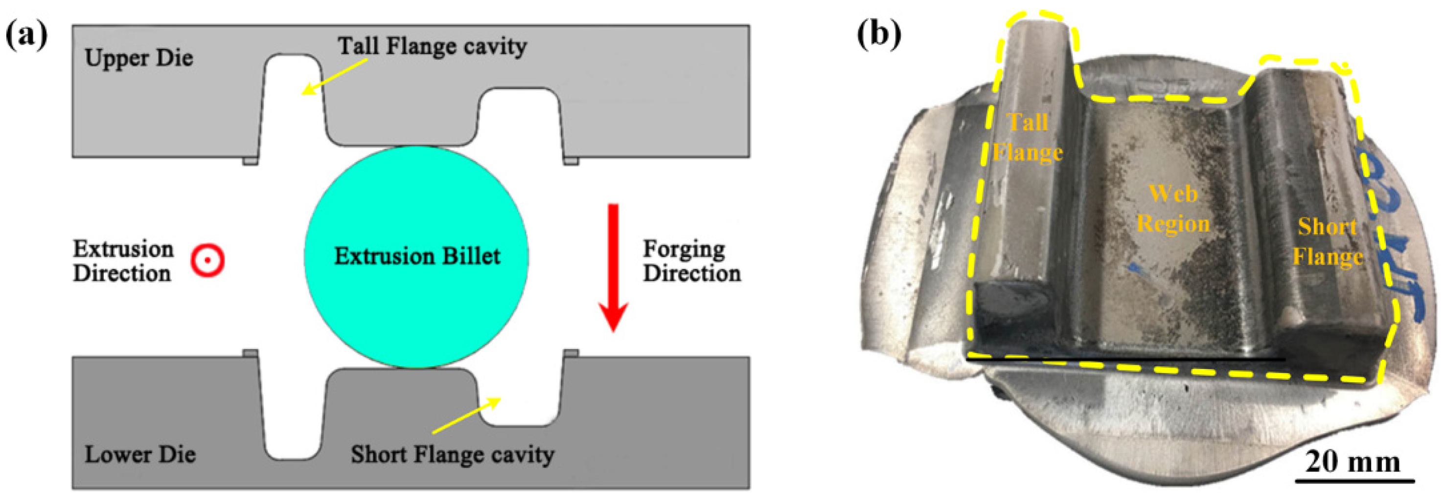
Commercially available ZK60 magnesium material (Luxfer MEL Technologies, Milwaukee, WI, USA) in the form of extrusion, annotated as ZK60E, with 5.5 wt.% Zn and 0.71 wt.% Zr (as per ASTM B91-12 standard [33]) was used for forging. The forging process was conducted at CanmetMATERIALS (Hamilton, ON, Canada). All forged parts were compressed into a closed die on a 500 ton hydraulic press with an inner I-beam-shaped cavity. At the beginning, the billet and tooling were heated separately to the experimental temperature for enough time to allow the attenuation of any thermal gradients. The billet was forged in the direction perpendicular to the extrusion orientation of the ZK60E material. The forging process was accomplished in a single step at a displacement rate of 20 mm/s under different temperatures of 250, 300, and 450 °C. The forging temperature was selected mainly based on the deformation characteristics of the magnesium alloy and consistent with the fatigue properties of ZK60 forged magnesium alloys forged at 250, 300, and 450 °C as investigated by other research team members [16]. The forging process and a forged I-beam are presented in Figure 1.
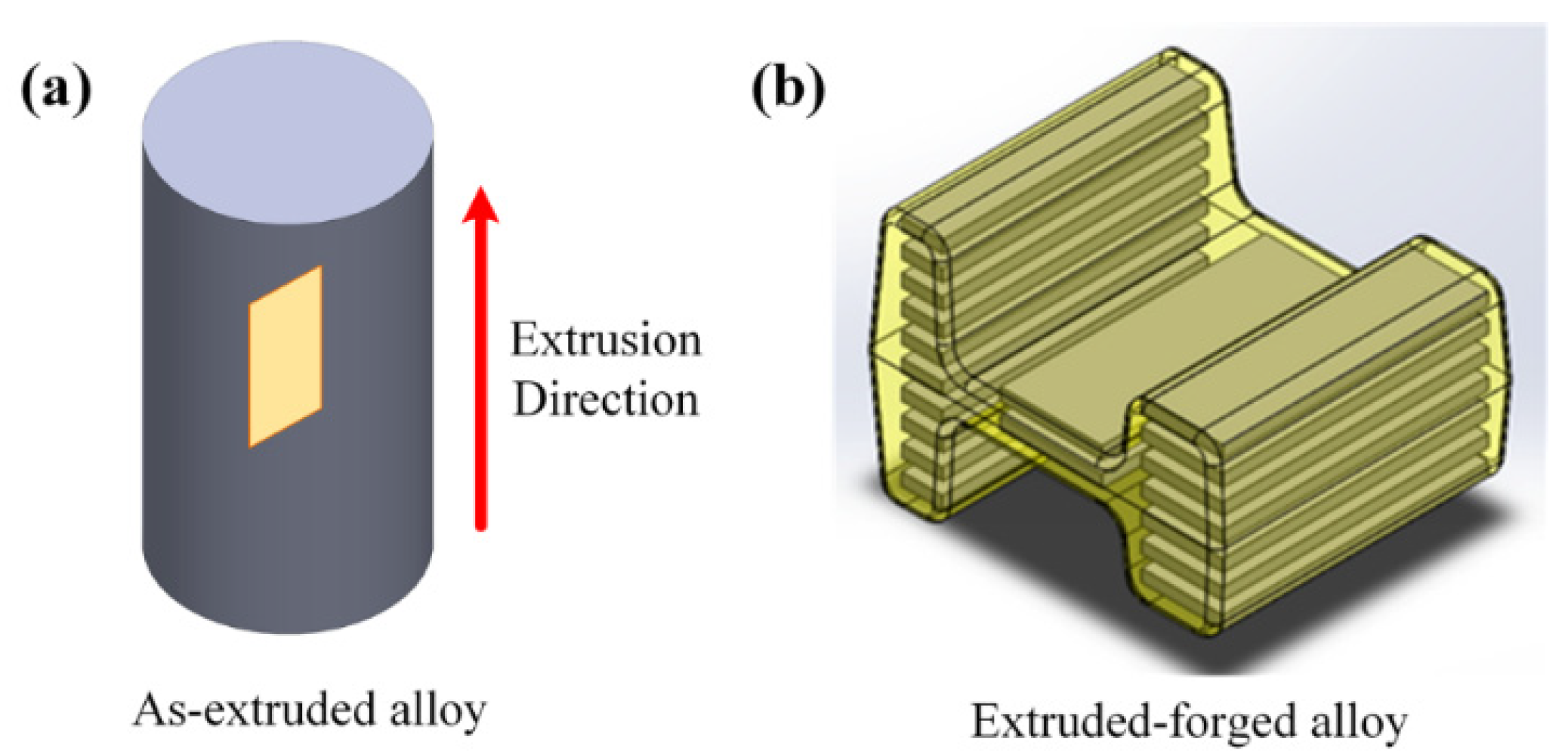
The extrusion-forged I-beam (ZK60EF) was cut into coupons of three different sizes due to the limitation of its dimensions. Coupons from the web region (60 mm × 25 mm × 3 mm) were used for the corrosion tests. Figure 2 shows the locations for coupon extraction from the billet and the I-beam. The as-extruded ZK60E alloy billet was cut into flat coupons of dimensions 50 mm × 25 mm × 3 mm.
For metallographic microstructure analysis, all specimens were ground using SiC emery papers from 400 grit up to 1200 grit, followed by polishing with the diamond paste. The etching reagent used was an acetic–picral solution consisting of 10 mL acetic acid glacial, 4.2 g picric acid, 10 mL H2O, and 70 mL ethanol (95%) [34]. After etching, the specimens were washed in a stream of alcohol, dried with a blast of air, and analyzed using an optical microscope.
2.2. MAO Treatment
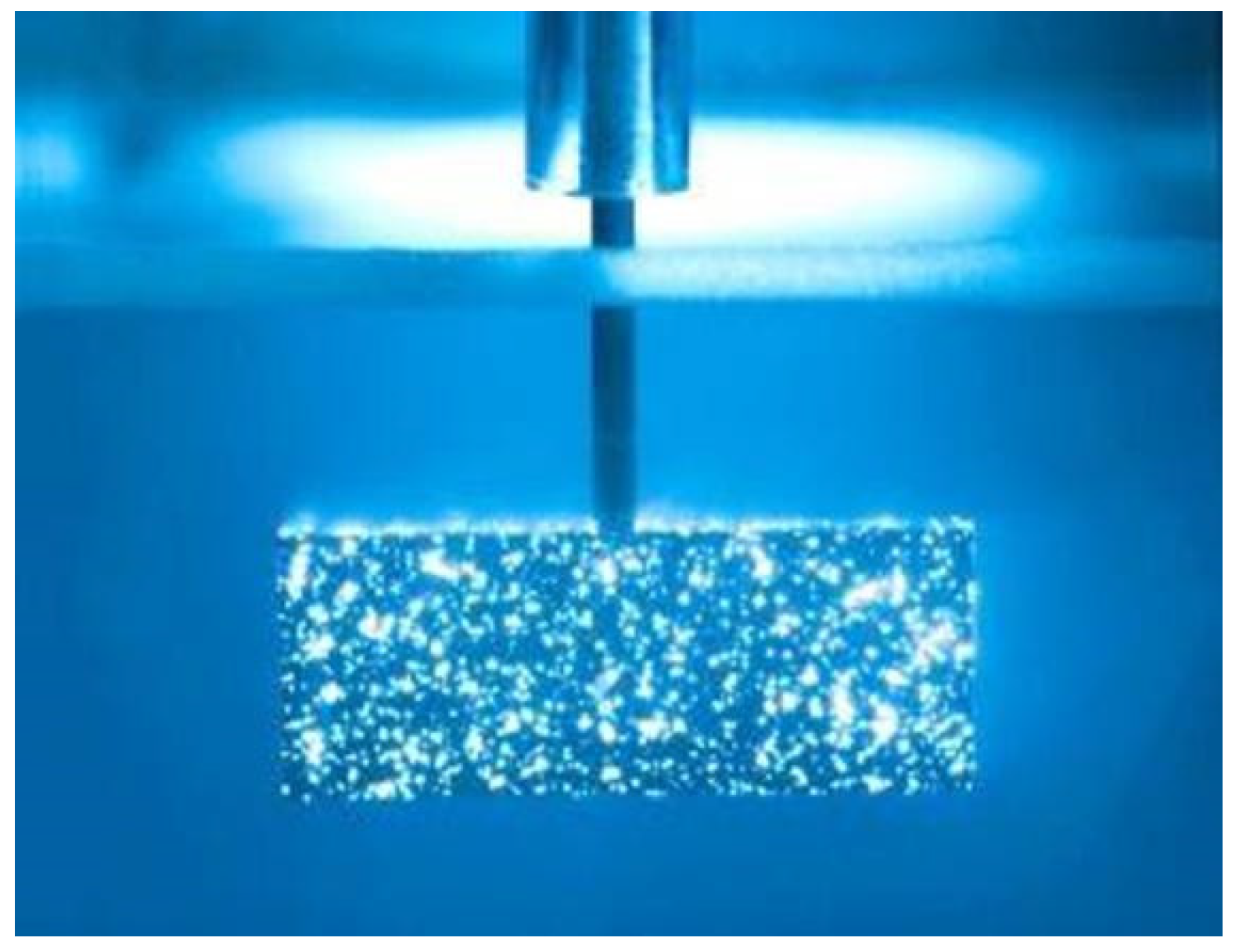
Prior to the MAO treatment, the specimens were polished using SiC emery papers from 320 up to 1200 grit, degreased using acetone, rinsed with deionized water, blown dry, and then stored in a desiccator immediately. In the present work, the MAO treatment was conducted using a single-pulse direct current power supply developed by Xi’an University of Technology (Xi’an, China) on a constant-current mode with a pulsed current at a frequency of 500 Hz. The electrolyte used for the MAO process contained 0.065 mol/L Na2SiO3, 15 mol/L KF, and 0.18 mol/L KOH. The pH of the silicate electrolyte solution was adjusted to 13 using a KOH solution. During the MAO process, the Mg alloy specimens were used as the anode and a stainless-steel plate as the cathode. The MAO treatment were performed at a constant current density of 34 mA/cm2 with a pulse width of 80 μs and treatment time of 10 min, as optimized in our previous work [35]. The MAO process is shown in Figure 3. After the MAO processing, the specimens were cleaned ultrasonically in trichloroethylene, rinsed with deionized water, and then air-dried and stored in the desiccator for further analysis.
The microstructure and surface morphology of the MAO coatings on different magnesium alloy substrates were analyzed using a Philips XL30 SFEG scanning electron microscope (SEM) equipped with the energy dispersive X-ray spectrometry (EDS). Electron backscatter diffraction (EBSD) analyses were conducted using a field emission gun scanning electron microscope (FEG-SEM) (FEI Nova NanoSEM-650) equipped with an EDAX EBSD detector.
2.3. Corrosion Characterization
To characterize the corrosion performances of the ZK60 Mg alloys, the uncoated and MAO-coated specimens were put in a salt fog chamber (Singleton Corp. SCCH) and exposed to the salt fog of 5 wt.% NaCl solution continuously for 840 h (35 days) at 35 °C and 100% relative humidity, according to the ASTM B-117 standard. For each alloy, multiple repetitive specimens were put in the chamber. Each day the specimens were examined by naked eyes for signs of corrosion. At certain time point (e.g., 4 h, 24 h, and 14 days), one of the repetitive specimens was extracted for SEM imaging and surface analysis to document the progression of corrosion.
The surface morphology of the corroded Mg alloy specimens was analyzed using SEM, EDS, and optical imaging to identify the distinct breakdown time of the MAO-coated ZK60 alloy specimens.
After 35 days, two specimens of each alloy were extracted from the corrosion testing chamber for the mass change measurements. Before the mass loss measurement, the corroded coupons were cleaned in a solution consisting of 200 g/L CrO3, 10 g/L AgNO3, and 20 g/L Ba(NO3)2 as per ASTM G1-03 standard. The mass changes per unit of surface area after exposure to the salt fog corrosion testing were recorded for each specimen.
2.4. Stress Corrosion Characterization
Considering the loading conditions of automobile components, a stress level of 80 MPa was used to investigate the stress corrosion properties of the wrought magnesium alloy ZK60 with and without MAO coating. The dimensions of the specimen and the details of the experimental device are shown in Figure 4. Figure 4 shows a customized stress corrosion testing method that was designed to assess the stress corrosion properties of the magnesium alloy quickly. Once the specimen was mounted on the tensile test machine and exposed to the corrosive medium, containing a 3.5 wt.% NaCl solution as the corrosive medium, it was loaded to 3.12 kN (stress level of 80 MPa) at a relatively fast rate provided by a PLT-5 microcomputer-controlled test machine and then maintained under this constant load for corrosion. The time to fracture for each specimen was recorded.
3. Results and Discussions
3.1. Microstructure Evolution of ZK60 during Forming
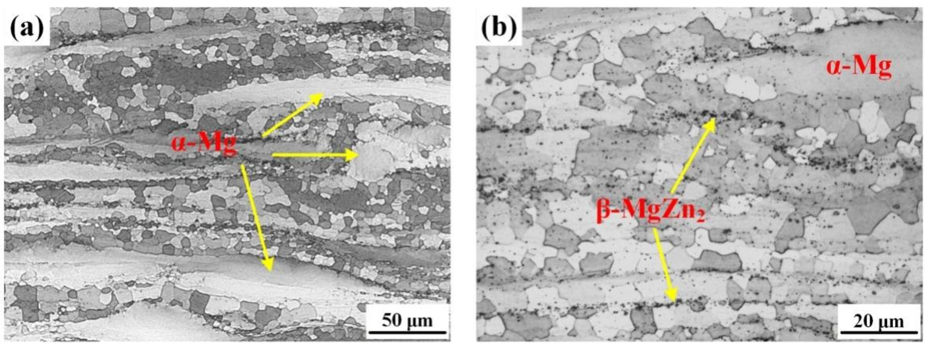
Figure 5 shows the optical microscopy images of the microstructure of the ZK60 extrusion (ZK60E) alloy, showing a mixture of small equiaxed grains and large bright elongated grains. Visible strings of second-phase particles were seen along the extrusion direction, precipitated around the small grains. These particles can act as effective nucleation sites for dynamic recrystallization (DRX) and also hinder grain growth, resulting in fine recrystallized grains in the vicinity of the second-phase particles. No twins were found in the microstructure of the ZK60E Mg alloy. Similar features were observed by Karparvarfard et al. [36]. Previous results of our work suggested that the secondary phase in the ZK60 alloy is mainly β-MgZn2, with a small quantity of Zn–Zr compound due to the relatively low content of Zr element in ZK60 [35,37]. Figure 6 shows the EBSD image of ZK60E alloy as extruded. It can be seen that the ZK60E was mainly composed of coarse and equiaxed grains. There were small-angle grain boundaries (misorientation angle 2°–15°) and big-angle grain boundaries (misorientation angle > 15°). The small-angle grain boundaries represent coarse grains that are evenly distributed. The big-angle grain boundaries (40°~90°) mainly refer to fine DRXed grains (i.e., equiaxed fine grains) formed during extrusion [38]. No deformation twins were found in the as-extruded specimen. The average DRX grain size of ZK60E was 8.1 ± 1.9 μm.
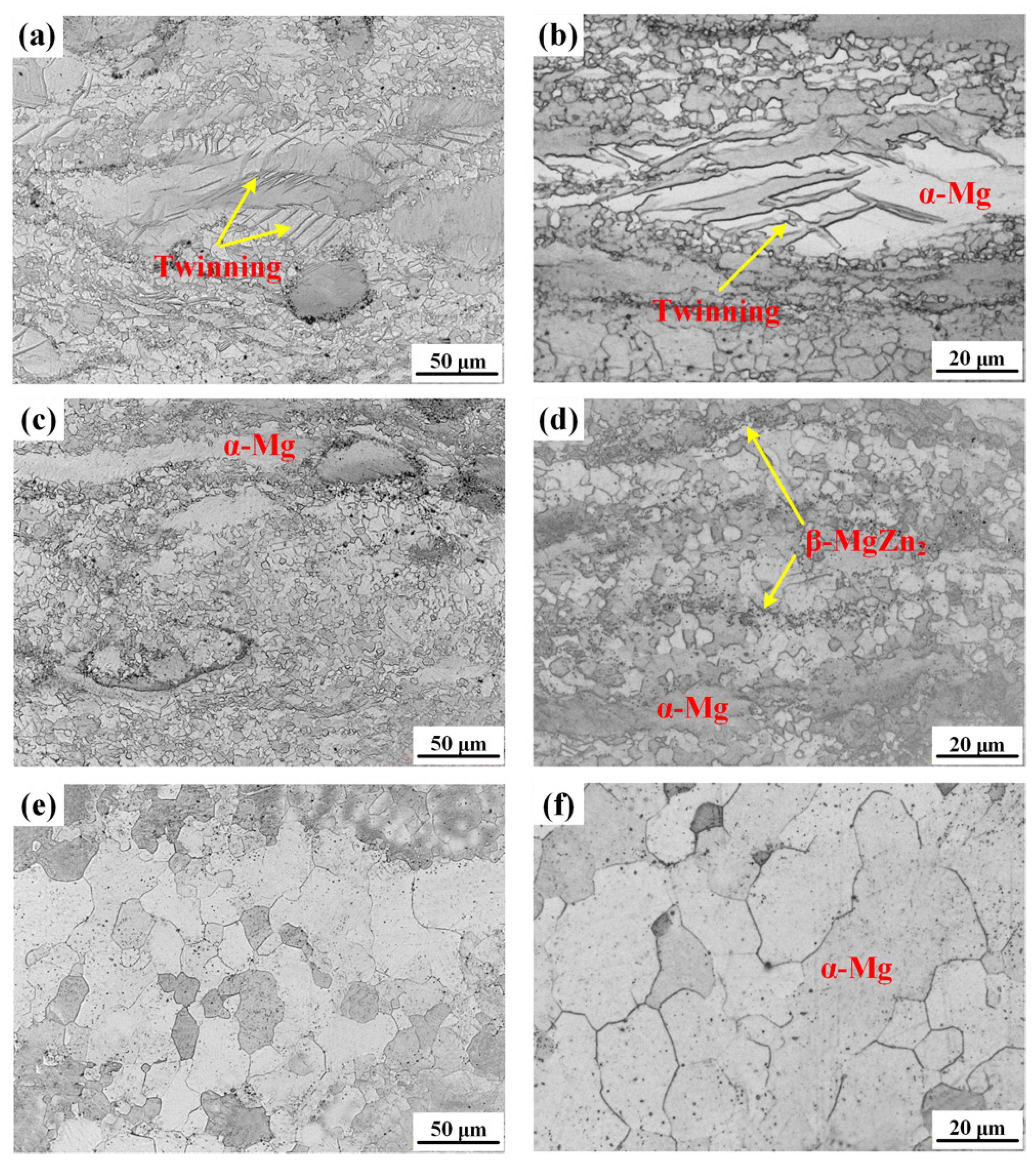
The microstructure of ZK60E alloy forged at the temperature of 250 °C (ZK60EF-250), 300 °C (ZK60EF-300), and 450 °C (ZK60EF-450) is shown in Figure 7. The ZK60EF-250 alloy, as shown in Figure 7a,b, had both small DRXed grains and large unrecrystallized grains oriented along the extrusion direction. It is worth noting that twinning is seen in the large unrecrystallized grains (Figure 7b). When forged at 300 °C, the ZK60E alloy showed features of incomplete DRX, i.e., the remaining elongated grains post deformation (Figure 7c,d). Its average DRXed grain size was much smaller than that of the ZK60E alloy (Figure 5). For the ZK60 alloy forged under 450 °C (Figure 7f) the average size of the recrystallized grains was larger than that of the ZK60EF-250 and ZK60EF-300 alloys. No obvious strings of secondary-phase particles were seen, which can be attributed to the dissolution of the secondary phase at the high forging temperature. Previous work indicated that the melting temperature associated with β-MgZn2 phases was about 340 °C [39]. Gao et al. [40] suggested that 325 °C was the critical temperature for the formation of β-phases in ZK60 alloy, above which the β-phases might not exist in the alloy. Therefore, almost all the MgZn2 compounds in the ZK60 alloy dissolved into the matrix at 450 °C. In addition, no evidence of twinning was seen in the ZK60EF-300 and ZK60EF-450 alloys. In the study by Barnett et al. [41] and Hadadzadeh et al. [37], it was shown that twinning tends to occur at lower deformation temperatures in ZK60 alloy. As the forging temperature increases, the DRXed grains grow larger, and the deformation occurs mainly through slipping, while twinning is suppressed. Therefore, the forging process mainly changed the grain size and quantity of the second phase. At low temperature (≤250 °C), twinning occurs first in the coarse grains. With the increase of the forging temperature (300 °C), the grains are refined and the difficulty of twinning increases, which is gradually controlled by dislocation climbing. At higher temperature, the grains continue to grow, and the second phase disappears.
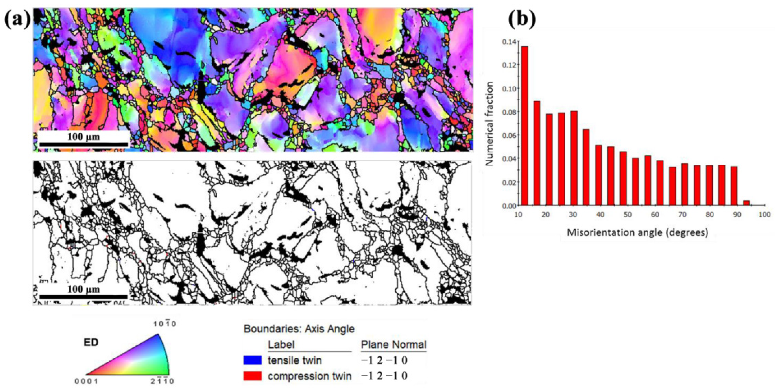
The EBSD data of ZK60EF-250 alloy is presented in Figure 8. It exhibits a pronounced fraction of big-angle grain boundaries at 80°~90°. When forged at 250 °C, many twins were seen in the alloy particularly in the coarse grains that were not recrystallized. Figure 8b also shows the misorientation angle plot that peaked at 86.3°, confirming the existence of compression twins. This can be explained by the fact that the actual forging temperature was low, and the DRX only nucleates in the area with high local energy storage such as the coarse grain boundary. The average grain size of ZK60EF-250 alloy was 4.6 ± 1.6 μm.
3.2. Microstructure of MAO Coatings
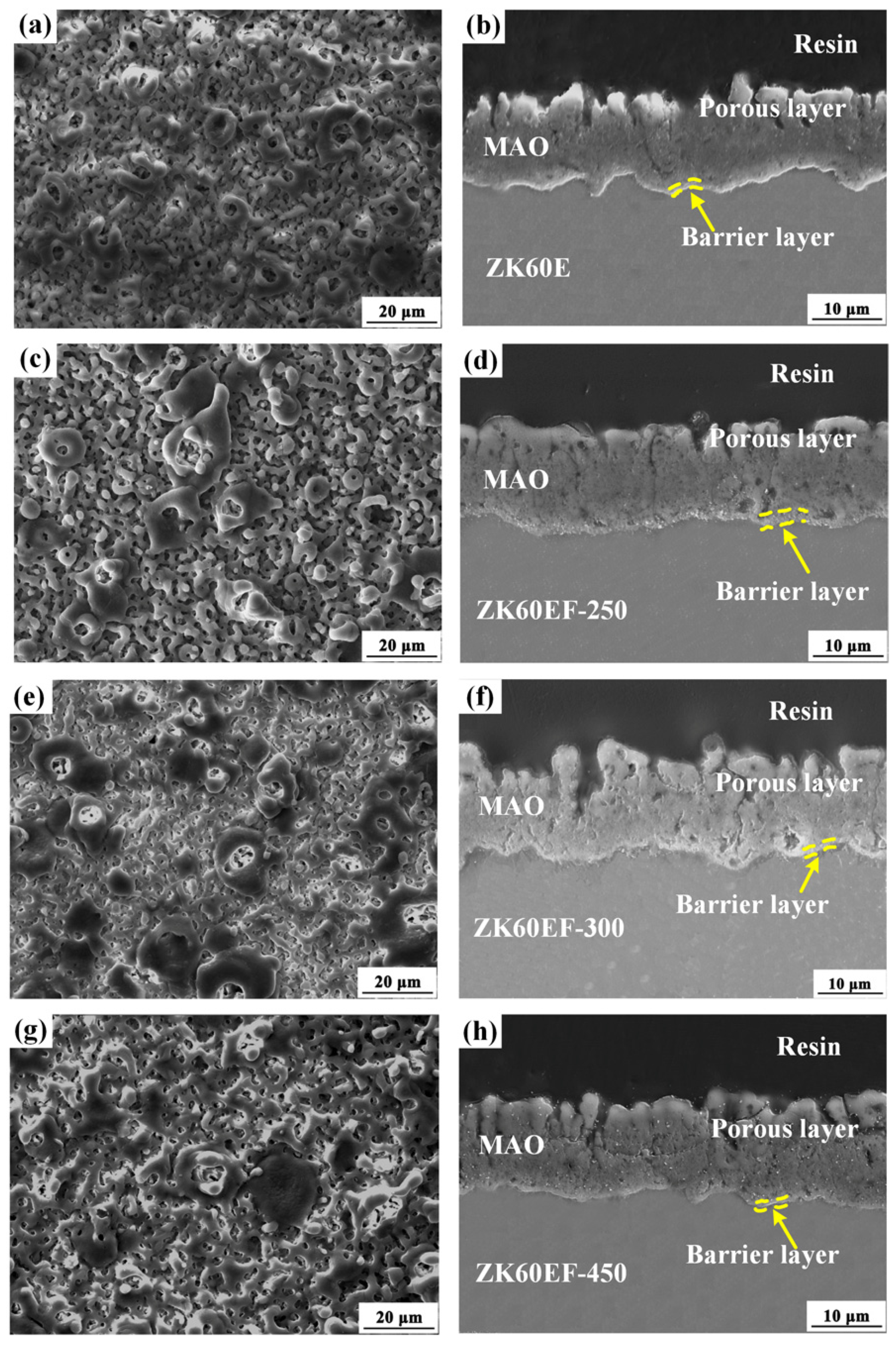
In this work, corrosion-protective MAO coatings were deposited on ZK60E and ZK60EF substrates. SEM images of the surface and cross-sectional morphologies of the ZK60E and ZK60EF alloys are presented in Figure 9. The ZK60 alloys show the micro-pores of different sizes and some large oxide particles on the coating surface (Figure 9a,c,e,g). There was no obvious difference in the surface morphology of the MAO coating on ZK60 alloys forged at various temperatures. The relatively uniform interconnected micro-pores and randomly distributed oxide particles on the MAO coating surface can be attributed to the throwing out of molten compounds and gas bubbles from the micro-arc discharge channels during the high-voltage MAO processing [26]. The cross-sectional micrographs of the MAO-coated ZK60 alloys are shown in Figure 9b,d,f,h. The MAO coating is a thick and uniform ceramic layer strongly adhered to the Mg alloy matrix, resulted from the oxidation and reactions of the substrate with the electrolyte solution in the process of MAO treatment. We could also see that the MAO coatings were composed of a barrier layer that was relatively dense and compact at the coating/substrate interface and a porous outer layer, which agrees well with what has been reported in the literature for MAO coatings on Mg alloys [28]. The cross-sectional micrographs show that there are micro-pores and micro-cracks in the porous layer, which can be penetrated by corrosive media. The protectiveness of the MAO coating against corrosion mainly comes from the continuous and dense barrier layer that blocks the passage of the corrosive ions and species. The average thickness of the MAO coating on the ZK60E, ZK60EF-250, ZK60EF-300, and ZK60EF-450 alloys was 15.9 ± 2.3, 15.4 ± 1.6, 15.6 ± 2.1, and 15.5 ± 1.8 μm, respectively.
Many researchers investigated the formation mechanisms of different phases on various Mg alloys during the MAO process [24]. Our previous work has studied the MAO coatings on AZ31B, AZ80, and ZK60 cast Mg alloy substrates [35]. The results showed that the MAO coatings mainly consisted of the ceramic compounds MgO, MgF2, Mg2SiO4, and other complex silicates. The alloying elements such as Al and Zn in the Mg alloy substrates were also detected in the MAO coatings via EDS analysis. For ZK series Mg alloys, the Zn element is mainly seen in the inner layer of the MAO coating. In the present work, the ZK60E and ZK60EF Mg alloy specimens were exposed to the same MAO processing, and thus, a similar phase and chemical composition of the MAO coating is expected.
3.3. Corrosion Morphology and Characterization
3.3.1. Corrosion Behavior of Uncoated ZK60 Specimens
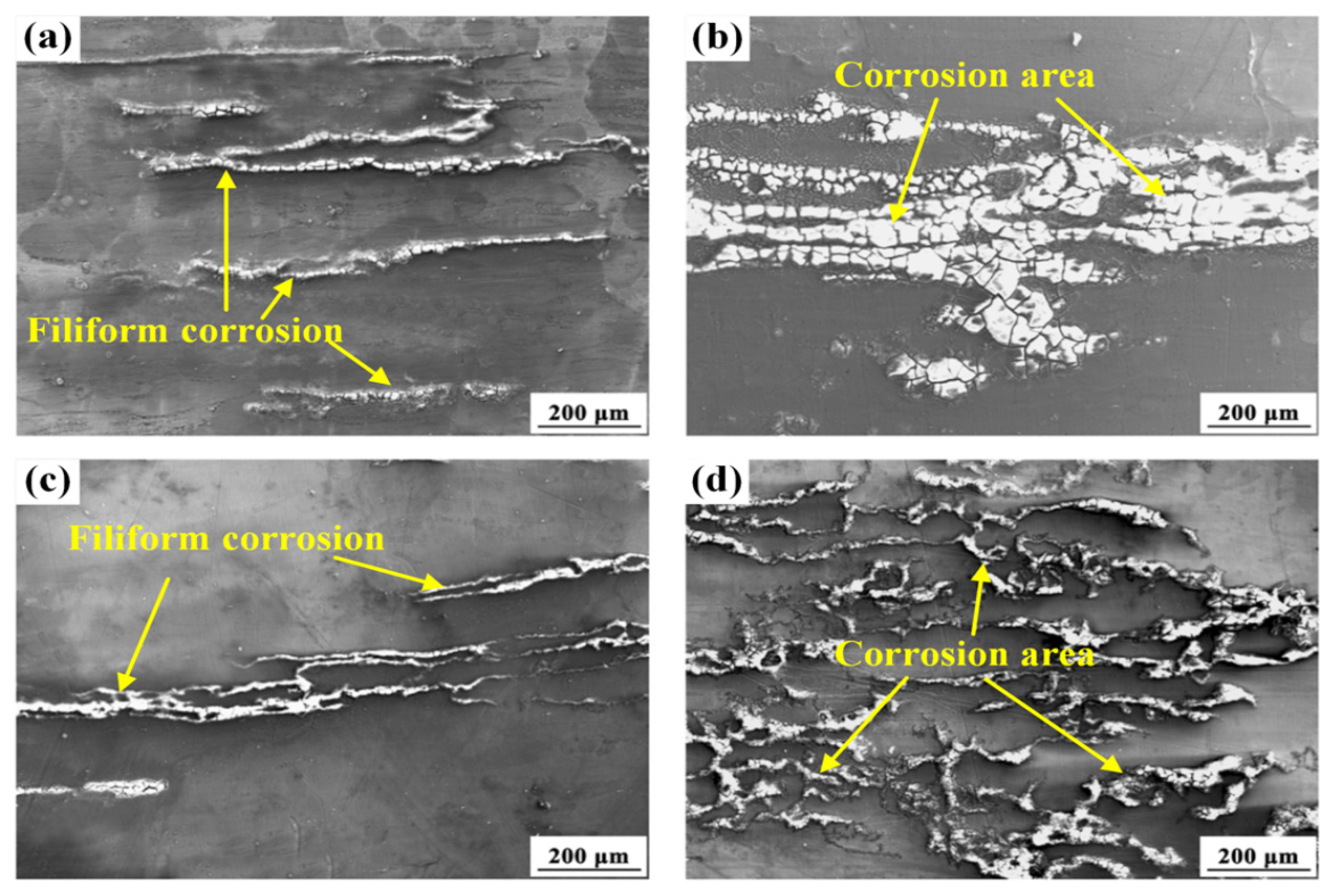
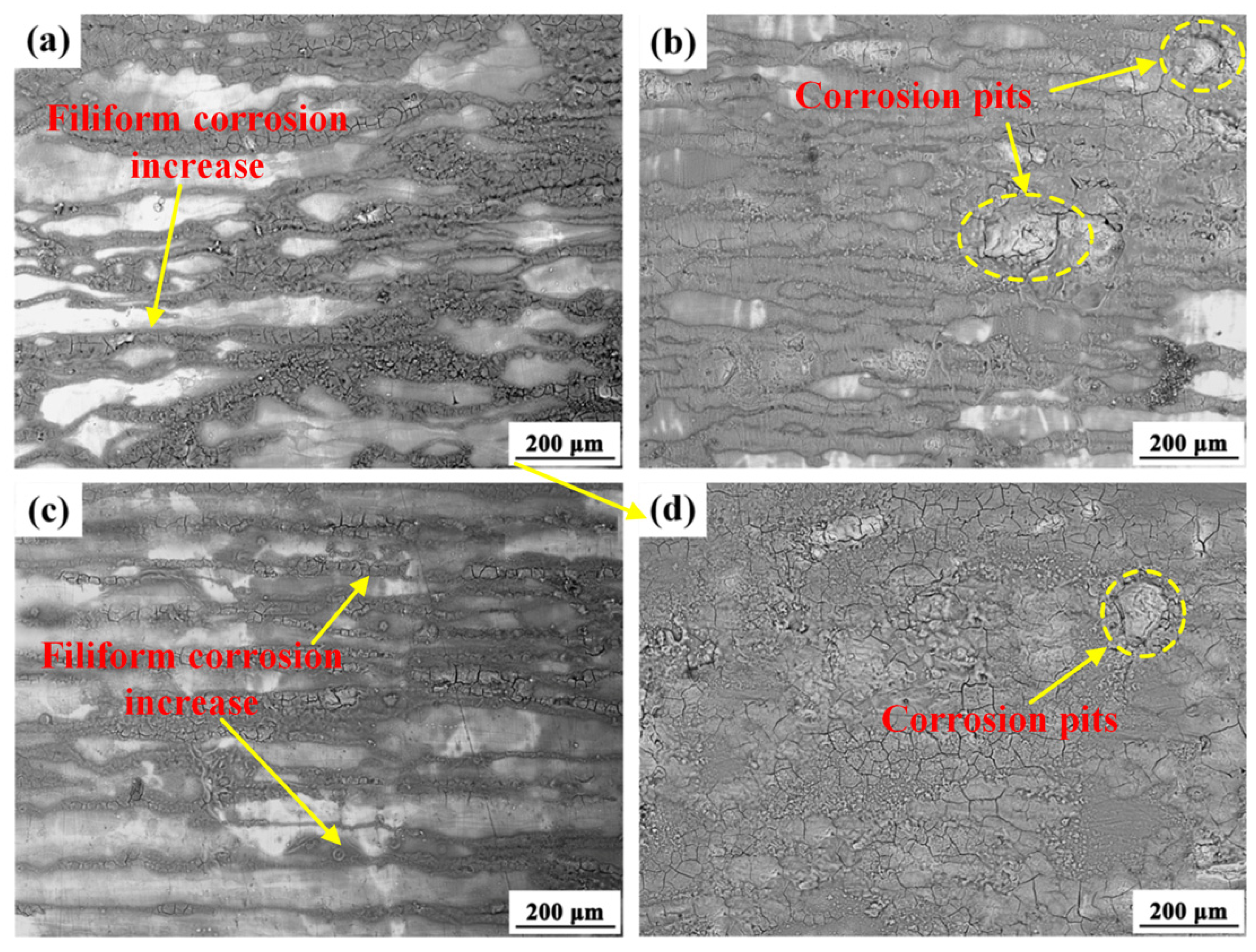
From the surface morphologies of ZK60E and ZK60EF specimens after 4 h in a salt spray environment (Figure 10), we observed that, at this stage, the corrosion occurred in a filiform corrosion mode. In the ZK60 alloy, Zr is used for grain refinement and alloy composition purification due to the formation of stable Zr-containing compounds [10]. The corrosion of the ZK60 alloy can be attributed mainly to the micro-galvanic corrosion effects between the α-Mg matrix and secondary-phase β-MgZn2 or Zn–Zr intermetallics, which are positioned along the extrusion direction at both grain boundaries and the interiors (Figure 5). As corrosion propagated along the corrosion filaments, filiform corrosion formed along the extrusion direction (Figure 10a,c). For the ZK60EF-250 alloy, the presence of twins accelerated its corrosion (Figure 10b), which can be ascribed to the galvanic corrosion between the twinned and untwined areas due to the difference in the crystallographic orientations [42]. It is generally believed that atoms in a twinned region are more active (possessing more energy) than the atoms in normal lattice positions. This leads to a potential difference between the twinned and untwined areas, causing micro-galvanic corrosion of the magnesium alloy [43]. For the ZK60EF-450 alloy, more severe filiform corrosion developed, covering almost the entire specimen surface (Figure 10d), which can be ascribed to the more dispersed secondary-phase particles and coarse grains formed under the forging temperature of 450 °C. It has been observed that a high density of grain boundaries (i.e., fine grains) in magnesium can prevent the rapid spread of corrosion [1]. The grain boundary is susceptible to oxidation, and thus, a high density of grain boundaries promotes the formation of an oxide barrier film, blocking the penetration of corrosive media. Accelerated corrosion was seen on the ZK60EF-450 alloy with coarse grains compared to the ZK60E and ZK60E-300 alloys with finer grains in the salt spray corrosive environment.
Figure 11 shows the surface morphologies of the ZK60 alloys after 24 h of salt spray test. Compared to the results of the 4 h salt spray test (Figure 10), pronounced corrosion propagation was seen on all specimens. However, a similar trend remained: more severe corrosion and, thus, more corrosion products were seen on ZK60EF-250 and ZK60EF-450 alloys.
3.3.2. Corrosion Behavior of MAO-Coated ZK60 Alloys
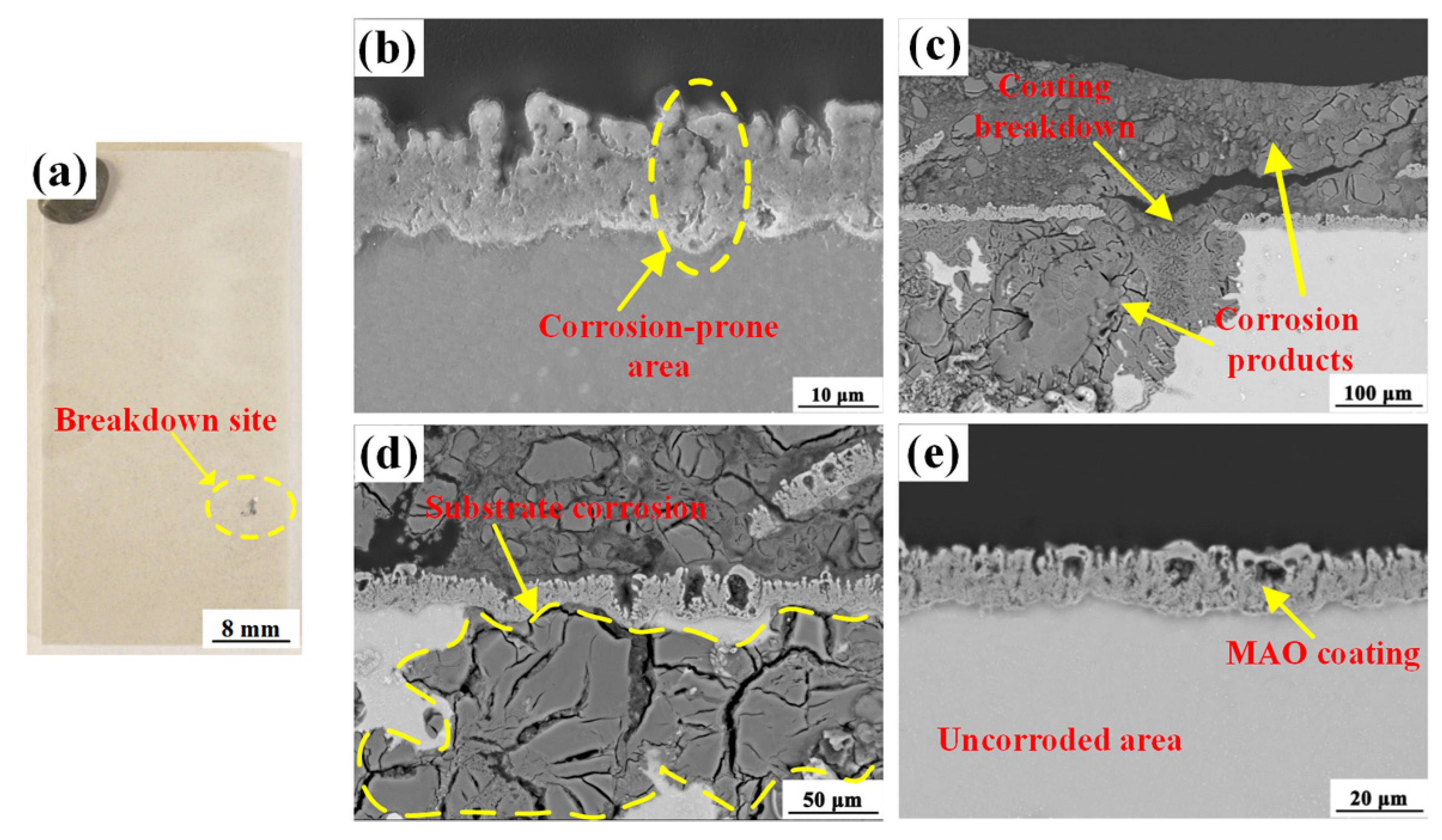
During the salt spray corrosion test, the specimens were examined daily by naked eyes for signs of corrosion. Both ZK60E and ZK60EF alloys showed the sign of corrosion initiation on the 14th day. Figure 12 gives the optical image of the breakdown site (Figure 12a) on the surface of the MAO-coated ZK60E alloy after 14 days of salt spray test and the SEM cross-sectional images of a coating crack (Figure 12b), the breakdown site (Figure 12c,d), and uncorroded area (Figure 12e). As found in our previous studies [44], the phase and chemical compositions of the MAO coating are mainly determined by the MAO treatment solution and chemical composition of the ZK60 substrates. In the present work, MAO coatings of similar composition, thickness, and microstructure were deposited on both ZK60E and ZK60EF alloys (Figure 9). The coatings provided comparable protection of the two alloys and, thus, broke down around the same time (i.e., 14 days) due to corrosion attack. It was evident that the aggressive salt solution can penetrate the MAO coating through micro-pores or cracks (Figure 12b) and react with the ZK60E or ZK60EF substrate, forming a large volume of corrosion products both above and beneath the MAO coating (Figure 12c). Once the coating breaks down, the corrosion propagates in the substrate under the MAO coating (Figure 12d). Thus, post coating breakdown, the corrosion performances of the specimens are dictated mainly by the substrate alloy.
3.3.3. Mass Loss Measurement
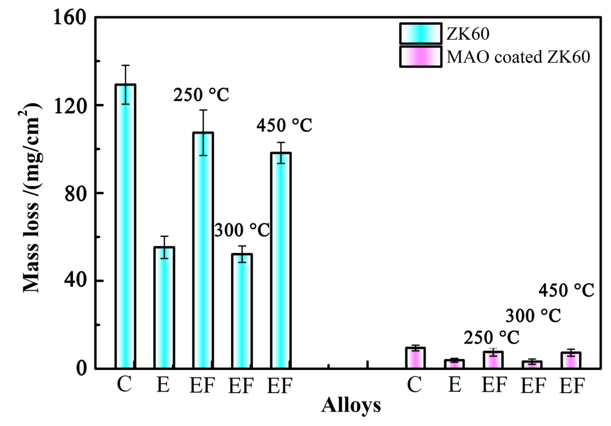
The results of the mass change measurement of the uncoated and MAO-coated ZK60 alloy specimens post 35 days of exposure to a continuous 5 wt.% NaCl neutral salt fog environment is presented in Table 1 and Figure 13. For comparison, the results of the as-cast ZK60 (ZK60C) alloy post the same test are also shown. Compared to the uncoated substrates, significantly less mass loss was seen for the MAO-coated specimens, demonstrating the robust protectiveness of the MAO coating on ZK60 alloys against corrosion. The cast ZK60 alloy specimen showed the biggest mass loss, which can be ascribed to their heterogeneous microstructure including coarse grains and defects such as micropores and inclusions from the casting process, as seen in our previous work [35]. The corrosion resistance of the ZK60 alloys of different processing history is ranked as ZK60EF-300 > ZK60E > ZK60EF-450 > ZK60EF-250 > ZK60C. The MAO-coated ZK60EF-300 alloy also exhibited the best corrosion resistance, among all MAO-coated ZK60 alloys. Thus, the uncoated and MAO-coated ZK60EF-300 alloy specimens were selected for further stress corrosion study.
3.4. Stress Corrosion Analysis
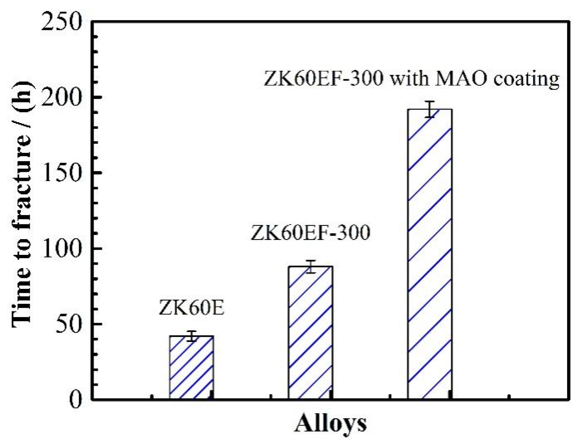
ZK60E and ZK60EF-300 alloys were selected for the stress corrosion test under a constant stress of 80 MPa in 3.5 wt.% NaCl solution. According to a previous study [36], the yield strength of ZK60E and ZK60EF-300 alloys is about 240 and 284 MPa, respectively. Therefore, the applied stress was approximately 30% of their yield strength, which is well within the elastic deformation range. However, the 3.5 wt.% NaCl solution was very aggressive and caused fast corrosion and dissolution of the uncoated Mg alloys. The time to fracture for ZK60E, ZK60EF-300, MAO-coated ZK60EF-300 alloys was 42, 88, and 192 h, respectively, as illustrated in Figure 14. The MAO coating significantly extended the time to fracture for the ZK60 magnesium alloy substrate exposed to corrosion and tensile stress simultaneously.
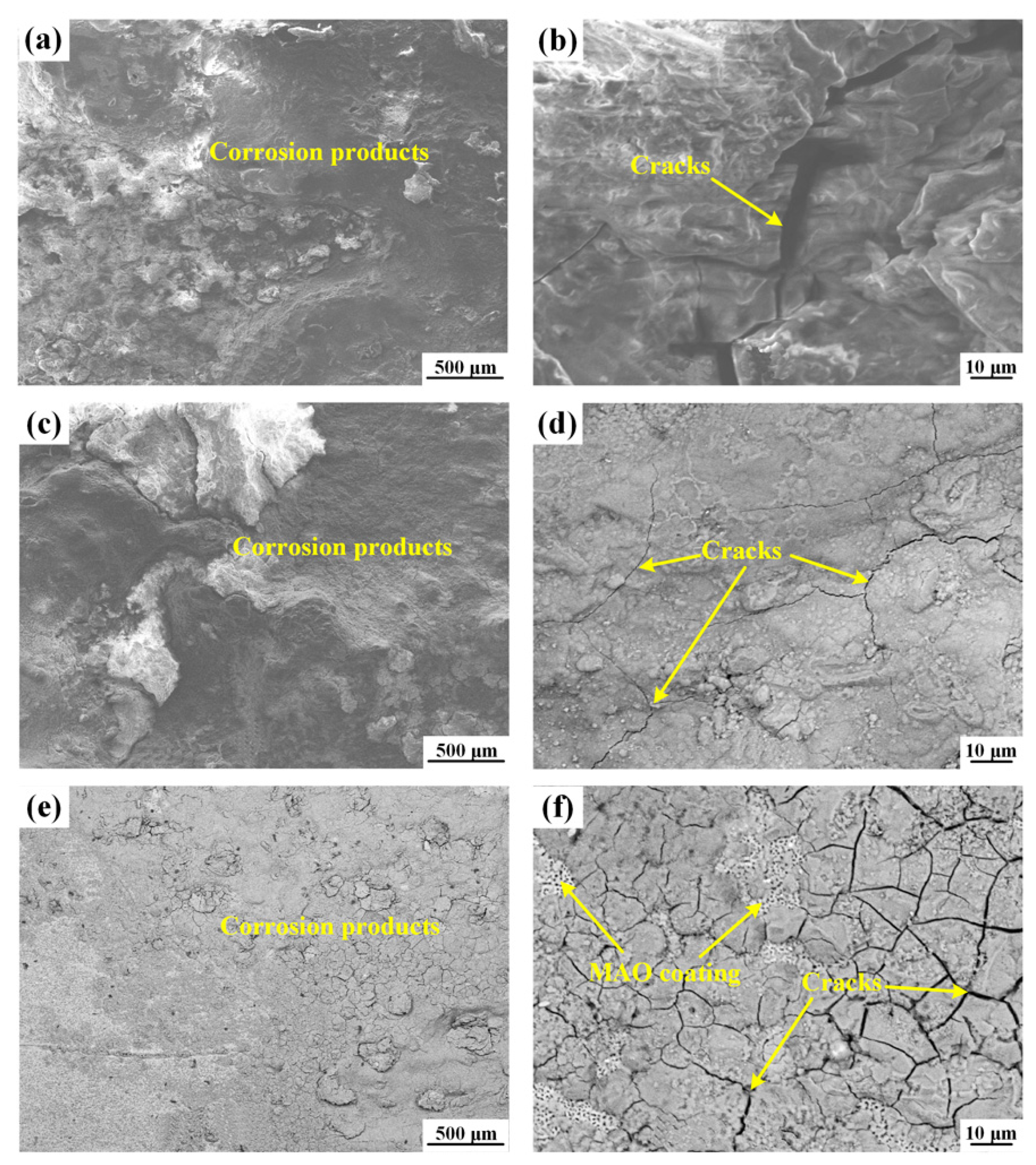
The corrosion of magnesium alloys was significantly accelerated by tensile stress in the corrosive medium. The surface morphologies of the ZK60E, ZK60EF-300, and MAO-coated ZK60EF-300 tensile specimens tested under 80 MPa in 3.5 wt.%NaCl solution are given in Figure 15. The specimen surfaces were fully covered with corrosion products (Figure 15a,c,e). Under tensile stress, the micro-cracks that nucleated at the filiform corrosion site in ZK60E alloy (Figure 10a) became large cracks, and the main crack propagated forward by coalescing micro-cracks ahead (Figure 15b). For the ZK60EF-300 alloy, thinner micro-cracks initiated at the filiform corrosion site (Figure 15d). The MAO coating improved the corrosion resistance of the substrate and delayed the formation of cracking. Under tensile stress, the micro-pores and micro-cracks of MAO coating can aggregate and propagate (Figure 15f), losing corrosion protectiveness and leading to a fracture failure in the end.
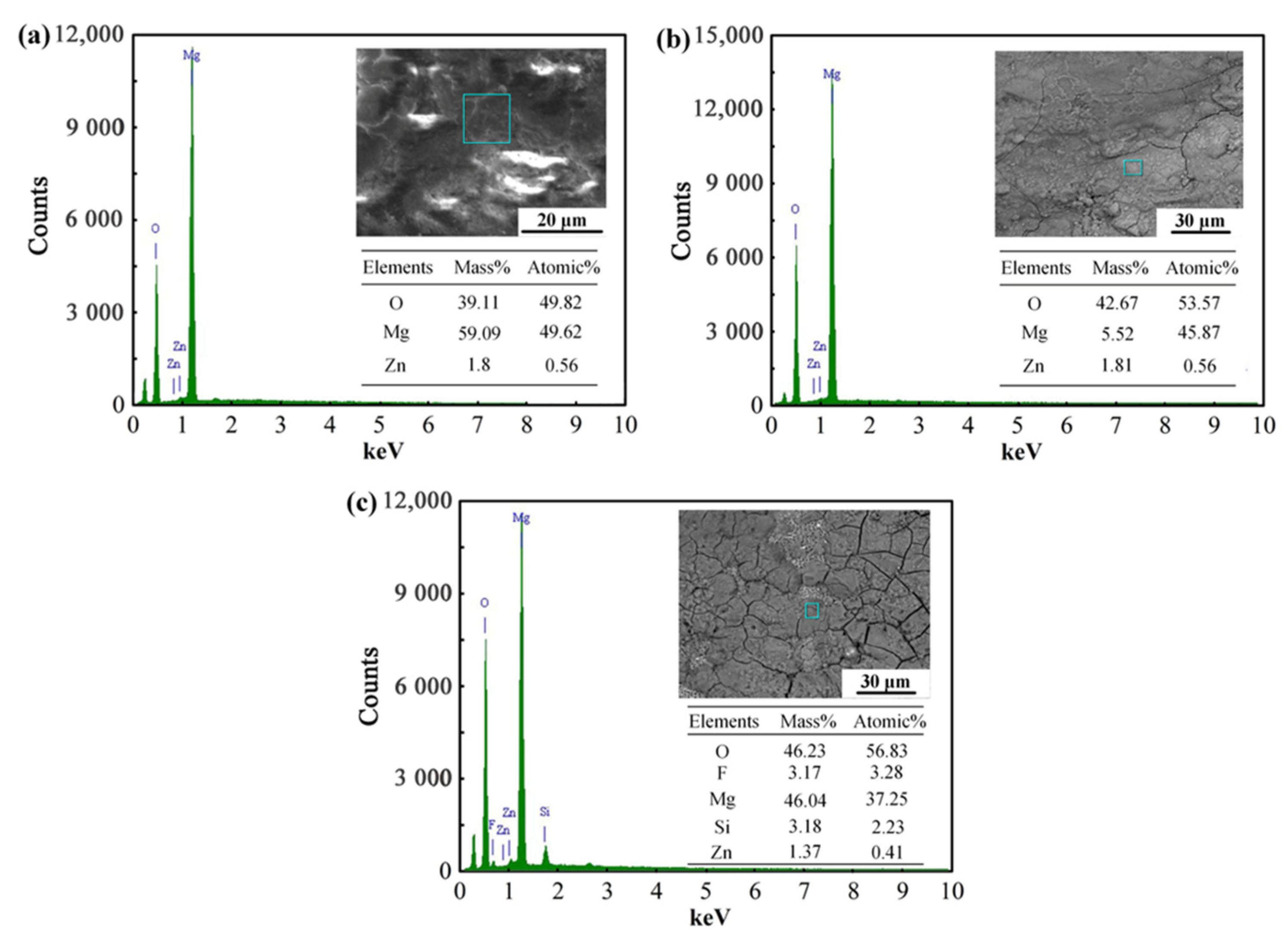
Representative EDS analyses of the corrosion surfaces of all specimens are shown in Figure 16. It indicated that the corrosion surfaces of ZK60E and ZK60EF-300 were primarily composed of O, Mg, and Zn. Therefore, the corrosion product of the Mg substrate was mainly MgO. For the MAO coating specimen, the corrosion surface consisted of O, F, Mg, Si, and Zn. It contained MgO (the corrosion product of the magnesium substrate) and the composition of the MAO coating (corrosion resistance phase Mg2SiO4 and MgF2).
4. Discussion
Small changes in the alloy chemistry, grain size, or volume fraction of the intermetallics in the Mg alloys can cause significant variations in their corrosion performances. The forging process can lead to the dynamic recrystallization and break-up of the secondary-phase agglomerates [45] and, thus, influence the corrosion properties of the Mg alloys significantly. The results of the static spray corrosion test showed that the corrosion resistance of wrought ZK60 alloys is influenced by two main factors: (i) metallurgical features (DRXed grain sizes and twinning) and (ii) the volume fraction and distribution of the intermetallics. Different deformation temperatures resulted in different grain sizes. Generally speaking, the smaller the grain size, the better the corrosion resistance. When forged at low temperatures, ZK60 alloy is prone to twinning, which can accelerate corrosion [42]. As for the intermetallics, if the secondary phase forms, a continuous network structure in the Mg alloy, the corrosion performance of the alloy can be significantly improved. However, when the forging temperature exceeds the melting temperature of the secondary phases (e.g., β-MgZn2 or β-Mg17Al12), the secondary-phase particles dissolve and DRXed grains grow coarser, deteriorating the corrosion performance. These results indicate that a thorough understanding of the effects of forging temperature on the corrosion behavior of wrought Mg alloys is essential to achieving improved corrosion performances [11,46].
With MAO surface coating, the chemical composition, microstructure, structural integrity (i.e., the number of defects such as through-pores and cracks) and thickness of the coating indicate its corrosion resistance. The MAO coating can effectively reduce the corrosion rate of the Mg alloys. However, once the coating breaks down, the problem of excessive corrosion re-emerges. Therefore, the corrosion properties of the MAO-coated specimens are determined not only by the quality of the coating but also by the substrate alloy.
Mechanical stress affects the corrosion of Mg alloys and has brought significant complications to the corrosion study of coated Mg alloys [47]. In the present work, the applied tensile stress accelerated the corrosion process (obtained from three repeated specimens) of the Mg alloys. This is due to the stress concentration phenomenon in the corrosion-weak areas such as filiform corrosion and corrosion pits, and the corrosion ions will preferentially erode these areas, resulting in the pitting area being more prone to further corrosion damage and cracks. Under a constant tensile load, the corrosion products are not compact and continuous enough to prevent the contacting of the underlying Mg surface with the aggressive ions [12,48]. The introduction of tensile stress to the uncoated ZK60 alloys caused the rupture of surface films that formed during corrosion, resulting in a higher corrosion rate. The protective MAO coating was dense, uniform, and strongly bonded to the substrate and, thus, inhibited the corrosion and fracture of the ZK60 alloy under the tensile stress.
5. Conclusions
The corrosion properties of the uncoated and MAO-coated ZK60 wrought Mg alloys were evaluated using advanced microstructural and surface analysis techniques, static long-term salt spray corrosion, and stress corrosion testing methods. The main findings were as follows:
- The corrosion performance of ZK60 alloys depended considerably on their microstructure including the grain size and β-phase morphology. It was found that the DRXed grain size increased with increasing forging temperature. The volume fraction of the secondary-phase precipitate β-MgZn2 in the forged material decreased with increasing forging temperatures. At 450 °C, there were no β-MgZn2 precipitates in the ZK60 after the forging. The presence of twins accelerated the corrosion of ZK60 alloy after forging at 250 °C. Corrosion test results showed that the processing of ZK60 extrusion via forging at 300 °C greatly improved its corrosion resistance.
- The MAO coatings provided robust protection of ZK60 series alloys with various processing history as compared to the corresponding uncoated Mg substrates. Similar breakdown time in the salt spray corrosion test was observed for MAO-coated ZK60 wrought Mg alloys with different processing history. Once the MAO coating broke down, the corrosion performances of the coated specimens were determined by the corrosion resistance of the substrate’s alloys.
- The applied tensile stress (80 MPa) accelerated the corrosion process of the ZK60 magnesium alloys, due to the rapture of surface films that formed during corrosion. The MAO coating provided robust corrosion protection of the substrate and significantly inhibited the corrosion and fracture of the ZK60 alloy under the tensile stress.
The findings of this work can be used to optimize the design and manufacturing process of Mg structural components and to develop a surface coating strategy for the corrosion protection of Mg alloys and components.
Author Contributions
Conceptualization, Y.X.; methodology, Y.X.; software, Y.X. and S.M.H.K.; validation, Y.X. and S.L.; formal analysis, Y.S.; investigation, Y.X.; resources, Y.X.; data curation, Y.X. and S.M.H.K.; writing—original draft preparation, Y.X. and X.P.; writing—review and editing, Y.X., X.P. and H.J.; visualization, Y.X.; supervision, X.P. and H.J.; project administration, H.J. and S.L. All authors have read and agreed to the published version of the manuscript.
Funding
This work was supported by the Natural Sciences and Engineering Research Council of Canada through the Automotive Partnership Canada (APC) program, grant number: APCPJ 459269-13, and the Natural Science Basic Research Plan in Shaanxi Province of China (No. 2022JQ-339). The funding support of the Xi’an key laboratory of high-performance oil and gas field materials, School of Material Science and Engineering, Xi’an Shiyou University, and the Shaanxi National Science Foundation (no. 2021JM-412) are also acknowledged.
Institutional Review Board Statement
Not applicable.
Informed Consent Statement
Not applicable.
Data Availability Statement
The data presented in this study are available on request from the corresponding author.
Conflicts of Interest
The authors declare no conflict of interest.
References
- Yang, Y.; Xiong, X.; Chen, J.; Peng, X.; Chen, D.; Pan, F. Research advances in magnesium and magnesium alloys worldwide in 2020. J. Magnes. Alloy. 2021, 9, 705–747. [Google Scholar] [CrossRef]
- Kumar, D.S.; Sasanka, C.T.; Ravindra, K.; Suman, K.N.S. Magnesium and its alloys in automotive applications—A Review. Columbia Int. Publ. 2015, 4, 12–30. [Google Scholar] [CrossRef]
- Jian Pan, Y.G. Sound Package Design for Lightweight Vehicles. SAE Tech. Pap. 2015, 1, 2–3. [Google Scholar] [CrossRef]
- Gryguc, A.; Behravesh, S.B.; Shaha, S.K.; Jahed, H.; Wells, M.; Williams, B.; Su, X. Low-cycle fatigue characterization and texture induced ratcheting behaviour of forged AZ80 Mg alloys. Int. J. Fatigue 2018, 116, 429–438. [Google Scholar] [CrossRef]
- Pahlevanpour, A.H.; Behravesh, S.B.; Adibnazari, S.; Jahed, H. Characterization of anisotropic behaviour of ZK60 extrusion under stress-control condition and notes on fatigue modeling. Int. J. Fatigue 2019, 127, 101–109. [Google Scholar] [CrossRef]
- Chen, J.; Ai, M.; Wang, J.; Han, E.H.; Ke, W. Stress corrosion cracking behaviors of AZ91 magnesium alloy in deicer solutions using constant load. Mater. Sci. Eng. A 2009, 515, 79–84. [Google Scholar] [CrossRef]
- Winzer, N.; Atrens, A.; Dietzel, W.; Song, G.; Kainer, K.U. Evaluation of the delayed hydride cracking mechanism for transgranular stress corrosion cracking of magnesium alloys. Mater. Sci. Eng. A 2007, 466, 18–31. [Google Scholar] [CrossRef] [Green Version]
- Jahed, H.; Roostaei, A.A. Cyclic Plasticity of Metals: Modeling Fundamentals and Applications; Elsevier Series on Plasticity of Materials; Elsevier: Amsterdam, The Netherlands, 2022. [Google Scholar]
- Wang, X.J.; Xu, D.K.; Wu, R.Z.; Chen, X.B.; Peng, Q.M.; Jin, L.; Xin, Y.C.; Zhang, Z.Q.; Liu, Y.; Chen, X.H.; et al. What is going on in magnesium alloys? J. Mater. Sci. Technol. 2018, 34, 245–247. [Google Scholar] [CrossRef]
- Merson, D.; Vasiliev, E.; Markushev, M.; Vinogradov, A. On the corrosion of ZK60 magnesium alloy after severe plastic deformation. Lett. Mater. 2017, 7, 421–427. [Google Scholar] [CrossRef]
- Madaj, M.; Greger, M.; Karas, V. Magnesium-alloy die forging for automotive application. Mater. Technol. 2015, 49, 267–273. [Google Scholar] [CrossRef]
- Merson, E.; Myagkikh, P.; Poluyanov, V.; Merson, D.; Vinogradov, A. On the role of hydrogen in stress corrosion cracking of magnesium and its alloys: Gas-analysis study. Mater. Sci. Eng. A 2019, 748, 337–346. [Google Scholar] [CrossRef]
- Wang, B.J.; Wang, S.D.; Xu, D.K.; Han, E.H. Recent progress in fatigue behavior of Mg alloys in air and aqueous media: A review. J. Mater. Sci. Technol. 2017, 33, 1075–1086. [Google Scholar] [CrossRef]
- Ma, Y.; Han, F.Y.; Liu, C.; Li, M.Z. Microstructure, texture evolution, and mechanical properties of ECAP-processed ZAT522 Magnesium alloy. Acta Metall. Sin. 2020, 33, 233–242. [Google Scholar] [CrossRef] [Green Version]
- Gryguć, A.; Behravesh, S.B.; Shaha, S.K.; Jahed, H.; Wells, M.; Williams, B.; Su, X. Multiaxial cyclic behaviour of extruded and forged AZ80 Mg alloy. Int. J. Fatigue 2019, 127, 324–337. [Google Scholar] [CrossRef]
- Karparvarfard, S.M.H.; Shaha, S.K.; Behravesh, S.B.; Jahed, H.; Williams, B.W. Fatigue Characteristics and modeling of Cast and Cast-Forged ZK60 Magnesium Alloy. Int. J. Fatigue 2018, 118, 282–297. [Google Scholar] [CrossRef]
- Wang, L.; Mostaed, E.; Cao, X.; Huang, G.; Fabrizi, A.; Bonollo, F.; Chi, C.; Vedani, M. Effects of texture and grain size on mechanical properties of AZ80 magnesium alloys at lower temperatures. Mater. Des. 2016, 89, 1–8. [Google Scholar] [CrossRef]
- Zhang, Z.; Huang, Y.; Rani Kasinathan, A.; Imani Shahabad, S.; Ali, U.; Mahmoodkhani, Y.; Toyserkani, E. 3-Dimensional heat transfer modeling for laser powder-bed fusion additive manufacturing with volumetric heat sources based on varied thermal conductivity and absorptivity. Opt. Laser Technol. 2019, 109, 297–312. [Google Scholar] [CrossRef]
- Wang, J.; Pang, X.; Jahed, H. Surface protection of Mg alloys in automotive applications: A review. AIMS Mater. Sci. 2019, 6, 567–600. [Google Scholar] [CrossRef]
- Han, L.; Zhang, Z.; Dai, J.; Li, X.; Bai, J.; Huang, Z.; Guo, C.; Xue, F.; Chu, C. The influence of alternating cyclic dynamic loads with different low frequencies on the bio-corrosion behaviors of AZ31B magnesium alloy in vitro. Bioact. Mater. 2022, 7, 263–274. [Google Scholar] [CrossRef]
- Xu, B.; Sun, J.; Han, J.; Yang, Z.; Zhou, H.; Xiao, L.; Xu, S.; Han, Y.; Ma, A.; Wu, G. Effect of hierarchical precipitates on corrosion behavior of fine-grain magnesium-gadolinium-silver alloy. Corros. Sci. 2022, 194, 109924. [Google Scholar] [CrossRef]
- Merson, E.; Poluyanov, V.; Myagkikh, P.; Merson, D.; Vinogradov, A. Inhibiting stress corrosion cracking by removing corrosion products from the Mg-Zn-Zr alloy pre-exposed to corrosion solutions. Acta Mater. 2021, 205, 116570. [Google Scholar] [CrossRef]
- Khalaj, G. Artificial neural network to predict the effects of coating parameters on layer thickness of chromium carbonitride coating on pre-nitrided steels. Neural Comput. Appl. 2013, 23, 779–786. [Google Scholar] [CrossRef]
- Vladimirov, B.V.; Krit, B.L.; Lyudin, V.B.; Morozova, N.V.; Rossiiskaya, A.D.; Suminov, I.V.; Epel’feld, A.V. Microarc oxidation of magnesium alloys: A review. Surf. Eng. Appl. Electrochem. 2014, 50, 195–232. [Google Scholar] [CrossRef]
- Khalaj, G.; Pouraliakbar, H. Computer-aided modeling for predicting layer thickness of a duplex treated ceramic coating on tool steels. Ceram. Int. 2014, 40, 5515–5522. [Google Scholar] [CrossRef]
- Jiang, B.L.; Ge, Y.F. Micro-Arc Oxidation (MAO) to Improve the Corrosion Resistance of Magnesium (Mg) Alloys; Woodhead Publishing: Sawston, UK, 2013; ISBN 9780857098962. [Google Scholar]
- Wang, Z.; Chen, G.; Chen, L.; Xu, L.; Lu, S. Degradation behavior of micro-arc oxidized ZK60 magnesium alloy in a simulated body fluid. Metals 2018, 8, 724. [Google Scholar] [CrossRef] [Green Version]
- Ezhilselvi, V.; Nithin, J.; Balaraju, J.N.; Subramanian, S. The influence of current density on the morphology and corrosion properties of MAO coatings on AZ31B magnesium alloy. Surf. Coat. Technol. 2016, 288, 221–229. [Google Scholar] [CrossRef]
- Cakmak, E.; Tekin, K.C.; Malayoglu, U.; Shrestha, S. The effect of substrate composition on the electrochemical and mechanical properties of PEO coatings on Mg alloys. Surf. Coat. Technol. 2010, 204, 1305–1313. [Google Scholar] [CrossRef]
- Gao, Y.; Wang, L.; Li, L.; Gu, X.; Zhang, K.; Xia, J.; Fan, Y. Effect of stress on corrosion of high-purity magnesium in vitro and in vivo. Acta Biomater. 2019, 83, 477–486. [Google Scholar] [CrossRef]
- Morri, A.; Ceschini, L.; Martini, C.; Bernardi, A. Influence of plasma electrolytic oxidation on fatigue behaviour of ZK60A-T5 magnesium alloy. Coatings 2020, 10, 1180. [Google Scholar] [CrossRef]
- He, X.; Liang, H.; Yan, Z.; Bai, R. Stress corrosion cracking behavior of micro-arc oxidized AZ31 alloy. Proc. Inst. Mech. Eng. Part C J. Mech. Eng. Sci. 2020, 234, 1640–1652. [Google Scholar] [CrossRef]
- ASTM B91-17; Standard Specification for Magnesium-Alloy Forgings. ASTM: West Conshohocken, PA, USA, 2017. [CrossRef]
- ASTM E340-15; Standard Method for Macro-Etching Metals and Alloys1. ASTM: West Conshohocken, PA, USA, 2002. [CrossRef]
- Xue, Y.; Pang, X.; Jiang, B.; Jahed, H.; Wang, D. Characterization of the corrosion performances of as-cast Mg–Al and Mg–Zn magnesium alloys with microarc oxidation coatings. Mater. Corros. 2020, 71, 992–1006. [Google Scholar] [CrossRef]
- Karparvarfard, S.M.H.; Shaha, S.K.; Behravesh, S.B.; Jahed, H.; Williams, B.W. Microstructure, texture and mechanical behavior characterization of hot forged cast ZK60 magnesium alloy. J. Mater. Sci. Technol. 2017, 33, 907–918. [Google Scholar] [CrossRef]
- Hadadzadeh, A.; Wells, M.A.; Kumar, S.; Jahed, H.; Williams, B.W. Role of compression direction on recrystallization behavior and texture evolution during hot deformation of extruded ZK60 magnesium alloy. J. Alloys Compd. 2017, 702, 274–289. [Google Scholar] [CrossRef]
- Jamali, A.; Ma, A.; LLorca, J. Influence of grain size and grain boundary misorientation on the fatigue crack initiation mechanisms of textured AZ31 Mg alloy. Scr. Mater. 2022, 207, 114304. [Google Scholar] [CrossRef]
- Wang, S.D.; Xu, D.K.; Chen, X.B.; Han, E.H.; Dong, C. Effect of heat treatment on the corrosion resistance and mechanical properties of an as-forged Mg-Zn-Y-Zr alloy. Corros. Sci. 2015, 92, 228–236. [Google Scholar] [CrossRef]
- Gao, X.; Nie, J.F. Structure and thermal stability of primary intermetallic particles in an Mg-Zn casting alloy. Scr. Mater. 2007, 57, 655–658. [Google Scholar] [CrossRef]
- Barnett, M.R.; Keshavarz, Z.; Beer, A.G.; Atwell, D. Influence of grain size on the compressive deformation of wrought Mg-3Al-1Zn. Acta Mater. 2004, 52, 5093–5103. [Google Scholar] [CrossRef]
- Wang, B.J.; Xu, D.K.; Dong, J.H.; Ke, W. Effect of the crystallographic orientation and twinning on the corrosion resistance of an as-extruded Mg-3Al-1Zn (wt.%) bar. Scr. Mater. 2014, 88, 5–8. [Google Scholar] [CrossRef]
- Song, G.L.; Xu, Z. Effect of microstructure evolution on corrosion of different crystal surfaces of AZ31 Mg alloy in a chloride containing solution. Corros. Sci. 2012, 54, 97–105. [Google Scholar] [CrossRef]
- Xue, Y.; Pang, X.; Jiang, B.; Jahed, H. Corrosion and corrosion fatigue performances of micro-arc oxidation coating on AZ31B cast magnesium alloy. Mater. Corros. 2019, 70, 268–280. [Google Scholar] [CrossRef]
- Liu, H.; Cao, F.; Song, G.L.; Zheng, D.; Shi, Z.; Dargusch, M.S.; Atrens, A. Review of the atmospheric corrosion of magnesium alloys. J. Mater. Sci. Technol. 2019, 35, 2003–2016. [Google Scholar] [CrossRef]
- Yoon, J.; Lee, S. Warm forging of magnesium AZ80 alloy for the control arm in an automobile. J. Automob. Eng. 2015, 229, 1732–1738. [Google Scholar] [CrossRef]
- Dubey, D.; Kadali, K.; Panda, S.S.; Kumar, A.; Jain, J.; Mondal, K.; Singh, S.S. Comparative study on the stress corrosion cracking susceptibility of AZ80 and AZ31 magnesium alloys. Mater. Sci. Eng. A 2020, 792, 139793. [Google Scholar] [CrossRef]
- Merson, E.; Poluyanov, V.; Myagkikh, P.; Merson, D.; Vinogradov, A. Fractographic features of technically pure magnesium, AZ31 and ZK60 alloys subjected to stress corrosion cracking. Mater. Sci. Eng. A 2020, 772, 138744. [Google Scholar] [CrossRef]
Figure 1.
(a) Schematic of the forging process and (b) a picture of the forged I-beam from an extrusion billet.
Figure 1.
(a) Schematic of the forging process and (b) a picture of the forged I-beam from an extrusion billet.

Figure 2.
The schematic of alloy coupons cut from the (a) as-extruded billet and (b) extruded-forged I-beam.
Figure 2.
The schematic of alloy coupons cut from the (a) as-extruded billet and (b) extruded-forged I-beam.

Figure 3.
The schematic diagram of the MAO process.

Figure 4.
The schematic of (a) tensile specimens and (b) stress-corrosion testing setup.

Figure 5.
The microstructure of ZK60 extrusion alloy at (a) low magnification and (b) high magnification.
Figure 5.
The microstructure of ZK60 extrusion alloy at (a) low magnification and (b) high magnification.

Figure 6.
(a) EBSD and inverse pole figure of undeformed ZK60 extrusion; (b) misorientation angle plot for undeformed ZK60E.
Figure 6.
(a) EBSD and inverse pole figure of undeformed ZK60 extrusion; (b) misorientation angle plot for undeformed ZK60E.

Figure 7.
Metallographic images of the ZK60EF alloy forged at the temperature of (a,b) 250 °C, (c,d) 300 °C, and (e,f) 450 °C.
Figure 7.
Metallographic images of the ZK60EF alloy forged at the temperature of (a,b) 250 °C, (c,d) 300 °C, and (e,f) 450 °C.

Figure 8.
(a) EBSD inverse pole figure of forged ZK60EF-250 alloy; (b) misorientation angle plot for forged ZK60EF-250 alloy.
Figure 8.
(a) EBSD inverse pole figure of forged ZK60EF-250 alloy; (b) misorientation angle plot for forged ZK60EF-250 alloy.

Figure 9.
The SEM micrographs of the surface and cross-section of MAO coatings on the (a,b) ZK60E, (c,d) ZK60EF-250, (e,f) ZK60EF-300, and (g,h) ZK60EF-450 Mg alloys.
Figure 9.
The SEM micrographs of the surface and cross-section of MAO coatings on the (a,b) ZK60E, (c,d) ZK60EF-250, (e,f) ZK60EF-300, and (g,h) ZK60EF-450 Mg alloys.

Figure 10.
SEM images of (a) ZK60E, (b) ZK60E-250, (c) ZK60EF-300, and (d) ZK60EF-450 alloy after salt spray corrosion for 4 h.
Figure 10.
SEM images of (a) ZK60E, (b) ZK60E-250, (c) ZK60EF-300, and (d) ZK60EF-450 alloy after salt spray corrosion for 4 h.

Figure 11.
Surface corrosion morphologies of (a) ZK60E, (b) ZK60EF-250, (c) ZK60EF-300, and (d) ZK60EF-450 in continuous salt spray environment for 24 h.
Figure 11.
Surface corrosion morphologies of (a) ZK60E, (b) ZK60EF-250, (c) ZK60EF-300, and (d) ZK60EF-450 in continuous salt spray environment for 24 h.

Figure 12.
The (a) optical image of the breakdown site and SEM cross-sectional images of (b) a crack in the coating, (c) the breakdown site, (d) corroded areas near the breakdown site, and (e) uncorroded areas for the MAO-coated ZK60E alloy after 14 days of salt spray test.
Figure 12.
The (a) optical image of the breakdown site and SEM cross-sectional images of (b) a crack in the coating, (c) the breakdown site, (d) corroded areas near the breakdown site, and (e) uncorroded areas for the MAO-coated ZK60E alloy after 14 days of salt spray test.

Figure 13.
The mass loss results of the uncoated and MAO-coated ZK60 alloy specimens post 35 days of salt spray test.
Figure 13.
The mass loss results of the uncoated and MAO-coated ZK60 alloy specimens post 35 days of salt spray test.

Figure 14.
The time to fracture for ZK60E, ZK60EF-300, and MAO-coated ZK60EF-300 alloys in 3.5 wt.% NaCl solution under 80 MPa stress.
Figure 14.
The time to fracture for ZK60E, ZK60EF-300, and MAO-coated ZK60EF-300 alloys in 3.5 wt.% NaCl solution under 80 MPa stress.

Figure 15.
The SEM images of the surfaces of (a,b) ZK60E, (c,d) ZK60EF-300, and (e,f) MAO-coated ZK60EF-300 tensile specimens tested in 3.5 wt.% NaCl solution under 80 MPa.
Figure 15.
The SEM images of the surfaces of (a,b) ZK60E, (c,d) ZK60EF-300, and (e,f) MAO-coated ZK60EF-300 tensile specimens tested in 3.5 wt.% NaCl solution under 80 MPa.

Figure 16.
Representation EDS analyses of specimens in 3.5 wt.% NaCl solution under 80 MPa, (a) ZK60E, (b)ZK60EF-300, and (c) ZK60EF-300 with MAO coating.
Figure 16.
Representation EDS analyses of specimens in 3.5 wt.% NaCl solution under 80 MPa, (a) ZK60E, (b)ZK60EF-300, and (c) ZK60EF-300 with MAO coating.


Table 1.
The average corrosion rate of uncoated and MAO-coated ZK60 alloy after 35 days of salt spray test.
Table 1.
The average corrosion rate of uncoated and MAO-coated ZK60 alloy after 35 days of salt spray test.
| Alloys | Mass Loss (mg/cm2) | Alloys | Mass Loss (mg/cm2) |
|---|---|---|---|
| ZK60C | 129.3 | MAO-coated ZK60C | 9.4 |
| ZK60E | 55.2 | MAO-coated ZK60E | 3.8 |
| ZK60EF-250 | 107.2 | MAO-coated ZK60EF-250 | 7.6 |
| ZK60EF-300 | 52.1 | MAO-coated ZK60EF-300 | 3.3 |
| ZK60EF-450 | 98.2 | MAO-coated ZK60EF-450 | 7.3 |
Publisher’s Note: MDPI stays neutral with regard to jurisdictional claims in published maps and institutional affiliations. |
© 2022 by the authors. Licensee MDPI, Basel, Switzerland. This article is an open access article distributed under the terms and conditions of the Creative Commons Attribution (CC BY) license (https://creativecommons.org/licenses/by/4.0/).
Share and Cite
MDPI and ACS Style
Xue, Y.; Pang, X.; Karparvarfard, S.M.H.; Jahed, H.; Luo, S.; Shen, Y. Corrosion Protection of ZK60 Wrought Magnesium Alloys by Micro-Arc Oxidation. Metals 2022, 12, 449. https://doi.org/10.3390/met12030449
AMA Style
Xue Y, Pang X, Karparvarfard SMH, Jahed H, Luo S, Shen Y. Corrosion Protection of ZK60 Wrought Magnesium Alloys by Micro-Arc Oxidation. Metals. 2022; 12(3):449. https://doi.org/10.3390/met12030449
Chicago/Turabian StyleXue, Yuna, Xin Pang, Seyyed Mohamad Hasan Karparvarfard, Hamid Jahed, Sheji Luo, and Yi Shen. 2022. "Corrosion Protection of ZK60 Wrought Magnesium Alloys by Micro-Arc Oxidation" Metals 12, no. 3: 449. https://doi.org/10.3390/met12030449
Note that from the first issue of 2016, this journal uses article numbers instead of page numbers. See further details here.