Article

Effect of Post-Heat Treatment Cooling Conditions on Microstructures and Fatigue Properties of Cobalt Chromium Molybdenum Alloy Fabricated through Selective Laser Melting

1
Removable Partial Prosthodontics, Oral Health Sciences, Graduate School of Medical and Dental Sciences, Tokyo Medical and Dental University, Tokyo 113-8549, Japan
2
Department of Conservative Dentistry and Prosthodontics, Faculty of Dentistry, Srinakharinwirot University, Bangkok 10110, Thailand
3
Department of Metallic Biomaterials, Institute of Biomaterials and Bioengineering, Tokyo Medical and Dental University, Tokyo 101-0062, Japan
*
Author to whom correspondence should be addressed.
Metals 2021, 11(7), 1005; https://doi.org/10.3390/met11071005
Submission received: 25 May 2021 / Revised: 18 June 2021 / Accepted: 22 June 2021 / Published: 23 June 2021

Abstract

:
Although post-heat treatment can improve the fatigue life of selective laser melting (SLM)-fabricated cobalt chromium molybdenum (CoCrMo) alloys, the effect of cooling conditions on the fatigue properties of such alloys remains unclear. In this study, we fabricated SLM CoCrMo alloy specimens and, after heat-treating them, cooled them either via furnace-cooling (FC) or air-cooling (AC). Subsequently, we analyzed their microstructures using scanning electron microscopy combined with energy-dispersive X-ray spectroscopy, electron backscattered diffraction, confocal laser scanning microscopy, and X-ray diffraction. Tensile and Vickers hardness (HV) tests and axial-fatigue tests were also conducted to assess their mechanical and fatigue properties, respectively. The microstructures of all samples showed homogeneous equiaxed grains, with the grains and precipitates of the AC samples (grain size: 84.9 μm) smaller than those of the FC samples (grain size: 109.7 μm). The AC samples exhibited better ductility than the FC samples. However, we observed no significant differences in the 0.2% yield strength and HV tests. The S–N curve derived from the fatigue tests showed that the AC samples had greater fatigue life than the FC samples. Therefore, a high cooling rate during post-heat treatment is effective in reducing grain and precipitate sizes, resulting in improved ductility and fatigue life.

1. Introduction

Cobalt chromium molybdenum (CoCrMo) alloys are widely used in the fabrication of biomedical devices, such as knee joints, orthopedic implants, and dental devices, because of their excellent mechanical properties and biocompatibility [1,2,3,4,5]. Over the past few decades, selective laser melting (SLM), an additive manufacturing technique, has become recognized as an advanced method for producing biomedical devices [5,6,7,8,9]. SLM allows for semi-automatic processing of metal parts with a high degree of geometric complexity while drastically reducing costs, energy consumption, and production time [9,10,11]. SLM-processed CoCr alloys have been widely used in the dental field to produce fixed and removable prostheses [1,2]. It has also been established that SLM technology enables the production of CoCr parts with superior properties, such as improved mechanical properties and less metal release, compared with parts fabricated via conventional casting techniques [5,9]. These properties are related to the high cooling rates employed during the SLM process, which generate finer-grained microstructures compared with those generated when conventional casting techniques are used [5,9,12]. However, one of the main drawbacks of SLM is that a residual stress is generated within the printed parts because of the distinctive thermal cycle pattern of rapid melting and cooling during the fabrication process [6,13,14,15]. This residual stress leads to micro-cracking or distortion, thereby degrading the resulting mechanical properties of the products [11,16]. Therefore, post-heat treatments are essential for reducing such residual stresses and improving the mechanical properties of the produced parts [11,13,16].
Previous studies have investigated how the heat treatment process could affect the microstructure, tensile properties, and fatigue strength of SLM-fabricated CoCr alloys [17,18,19,20,21]. Seki et al. [17] reported that CoCrMo samples heat-treated at 1150 °C for 1 h showed substantial improvements in fatigue strength compared with as-built specimens. This result was attributed to the occurrence of recrystallization and the disappearance of the molten pool boundaries due to heat treatment. Dong et al. [22] found that CoCrMoW alloys heat-treated at 1200 °C for 1 h exhibited a higher fatigue life, tensile strength, and ductility than conventional cast CoCrMoW alloys did. The improvement in properties was attributed to the fine grains and precipitates in the SLM-processed alloys; these produced secondary cracks that deviated from the fatigue crack, which, in turn, reduced the crack growth rate. These studies confirm that the tensile and fatigue properties of alloys are dependent on their microstructures.
Heat treatment consists of two main processes—heating and cooling—and the cooling rate affects the resulting microstructures as well. Lu et al. [23] compared the microstructures and tensile properties of CoCrW alloys heated for 1 h at 1150 °C and subsequently cooled via water quenching or furnace cooling (FC). They reported that the alloys quenched using water showed greater tensile strength than the alloys subjected to FC [23]. Therefore, microstructural changes induced by different cooling rates may affect the fatigue properties of alloys. However, to the best of our knowledge, no studies thus far have investigated the effect of cooling rates on the fatigue behavior of SLM-processed CoCr alloys.
In this study, we investigated the influence of post-heat treatment cooling conditions on the fatigue behaviors of SLM-processed CoCrMo samples under tension–tension cyclic loads. According to the company guidelines for use of the CoCrMo alloy powder used in this study, the post heat treatment for relieving residual stress is 1150 °C for 6 h [24]. Kajima et.al [16] and Razavi et al. [19], also reported that the heat treatment at 1150 °C for 6 h caused significant changes in the microstructure, with homogenization and recrystallization leading to isotropic properties. However, our previous study showed that a 6 h heat treatment of removable partial denture clasp samples produced coarser precipitates on the grain boundaries than a 1 h heat treatment, resulting in lower fatigue strength [18]. Therefore, in this study, we performed a heat treatment at 1150 °C for 1 h. Subsequently, we employed two different cooling rates and analyzed the resulting microstructures, tensile properties, and fatigue properties of the alloys.

2. Materials and Methods

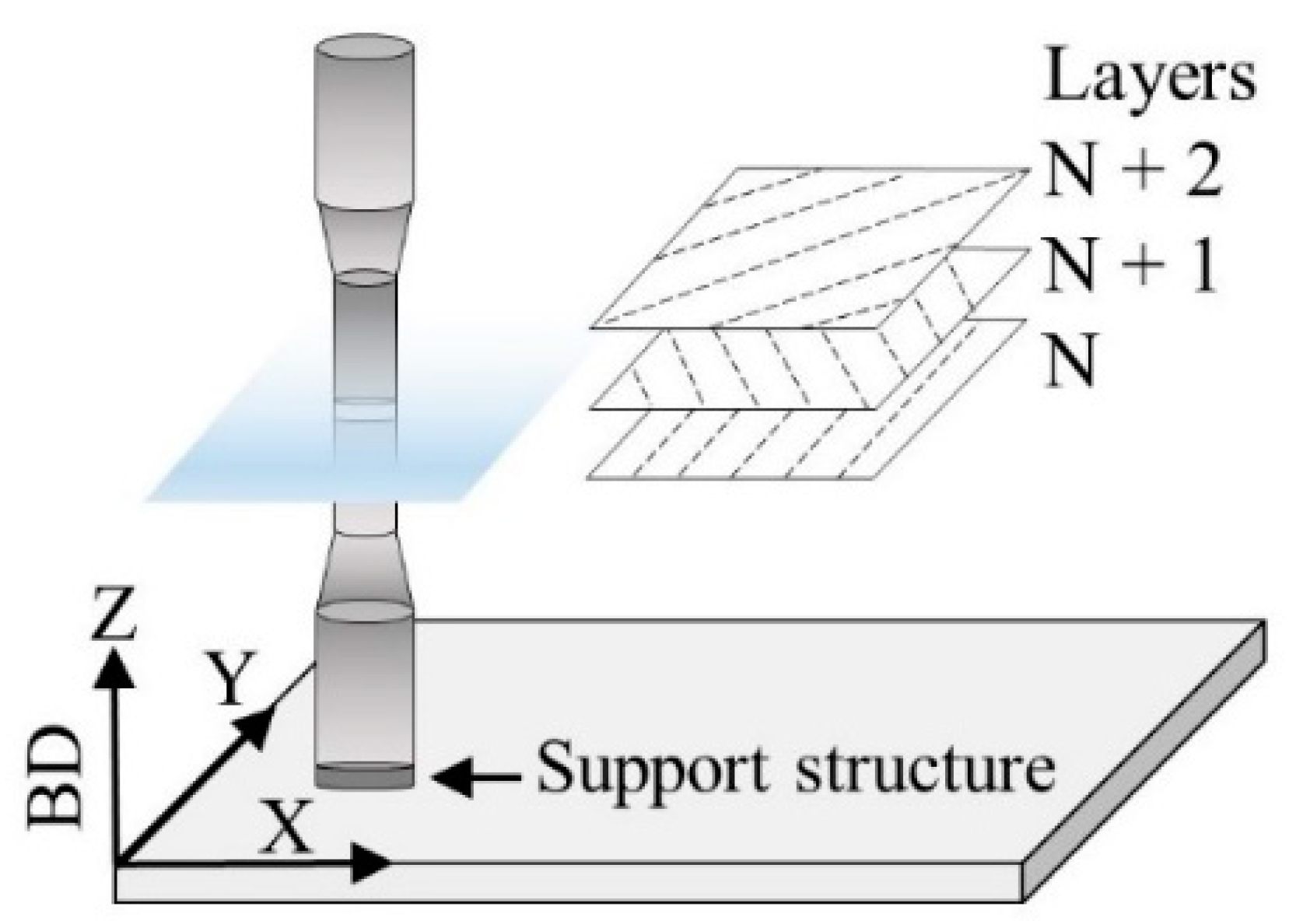
2.1. Specimen Preparation

We used commercial CoCrMo powder (MP1, EOS, Krailling, Germany) to manufacture the samples. Table 1 shows the composition of the CoCrMo powder. We prepared dumbbell-shaped specimens with a diameter of 3 mm and a length of 18 mm using an SLM machine (EOSINT M280, EOS, Krailling, Germany) equipped with a fiber laser. The SLM machine was operated using standard deposition parameters for MP1 with a laser power of 195 W on a platform temperature 40 °C under a nitrogen atmosphere. The samples were fabricated with their longitudinal axes parallel to the printing direction, as shown in Figure 1. The specimens were divided into two groups, and the heat treatment was then performed in the following sequence: (1) heating the furnace from room temperature to 600 °C, (2) maintaining the temperature for 30 min, (3) heating the furnace to 1150 °C, (4) maintaining the temperature for 1 h, and (5) switching off the heating machine. The heating was performed under an argon gas atmosphere with a ramp rate of 10 °C/min. The specimens in one group were cooled to room temperature inside the furnace; this group was denoted as FC. We monitored the temperature in the furnace using a thermocouple and it took about 2 h and 30 min to return to the room temperature. The specimens in the other group, denoted as AC, were cooled to room temperature in air, according to the following steps: opening the furnace door as soon as the 1 h holding time was complete and (2) extracting the specimens from the furnace and cooling them to room temperature in air. It took approximately 20 min to complete.

2.2. Microstructural Analysis

The specimens were transversely cut to form rod-shaped specimens for microstructural analysis (3 mm diameter, 1 mm height), as shown in Figure 1. These rod-shaped specimens were then polished sequentially using waterproof emery paper (320–1000 grit), a 9 μm diamond suspension, and a 0.04 μm colloidal silica suspension. Subsequently, the specimens were etched in a solution of H2SO4/CH3OH (5:95, v/v) at 15 V and 268–273 K. The microstructure was observed using a scanning electron microscope with energy-dispersive X-ray spectroscopy (SEM-EDS; S-3400NX, Hitachi, Tokyo, Japan) under an accelerating voltage of 15 kV, as well as using a confocal laser scanning microscope (CLSM; OLS4000, Olympus, Tokyo, Japan) and through electron backscatter diffraction analysis (EBSD; TexSEM Laboratories, Inc., Provo, UT, USA) using a field-emission scanning electron microscope (XL-30FEG, Philips, The Netherlands). Using SEM-EDS, spot analyses were performed to evaluate the compositional segregation in the samples. An X-ray diffractometer (XRD; D8 Advance, Bruker-AXS, Karlsruhe, Germany) was used to observe phase transformations using Cu Kα radiation at a voltage of 40 kV and a current of 40 mA in the 2θ scanning range of 40°–80°. The ε-HCP phase volume fractions were determined by the Sage and Guillaud method [25].
HCP   ( wt % ) = { I ( 10 1 ¯ 1 ) hcp I ( 10 1 ¯ 1 ) h c p + 1.5 I ( 200 ) f c c } × 100

2.3. Mechanical Properties

An Instron universal testing machine (AG-2000B, Shimadzu, Kyoto, Japan) was used to perform uniaxial tensile tests at an initial strain rate of 1.1 × 10⁻³ s−1 with dumbbell- shaped specimens (n = 5 for both conditions). A non-contact optical strain gauge was used to measure the strain values. The ultimate tensile strength (UTS), 0.2% yield strength (0.2% YS), and elongation of the tested specimens were calculated from the stress–strain curves. Vickers hardness (HV) tests were performed on the rod specimens (n = 3 for each condition) for 30 s with a 100 g load. All average values and standard deviations were calculated from five data points for each sample.

2.4. Fatigue Test

Before the fatigue strength test, to reduce the surface roughness (Ra), the dumbbell-shaped specimens were polished using waterproof emery paper (from 320 grit to 800 grit) until they started becoming reflective. Ra was determined using a CLSM five times for each sample. The fatigue test was performed using an electrohydraulic fatigue test machine (EHF-FB10kN-10LA, Shimadzu, Kyoto, Japan) with various sinusoidal cyclic tensile forces (Table 2). Each test was conducted at a frequency of 10 Hz, in accordance with JIS T 0309:2009 [26,27]. The fatigue tests were continued until the sample fractured or 107 cycles were completed. However, the number of samples available for this test was limited. As a result, the number of samples provided to each stress level was different. Scanning electron microscopy (SEM) was used to examine the fracture surfaces after the fatigue tests.

2.5. Statistical Evaluation

The Mann-Whitney U-test was used to statistically evaluate the data collected from the Ra, HV, and tensile measurements. Statistically significant differences between data were considered to correspond to a p-value less than 0.01.

3. Results

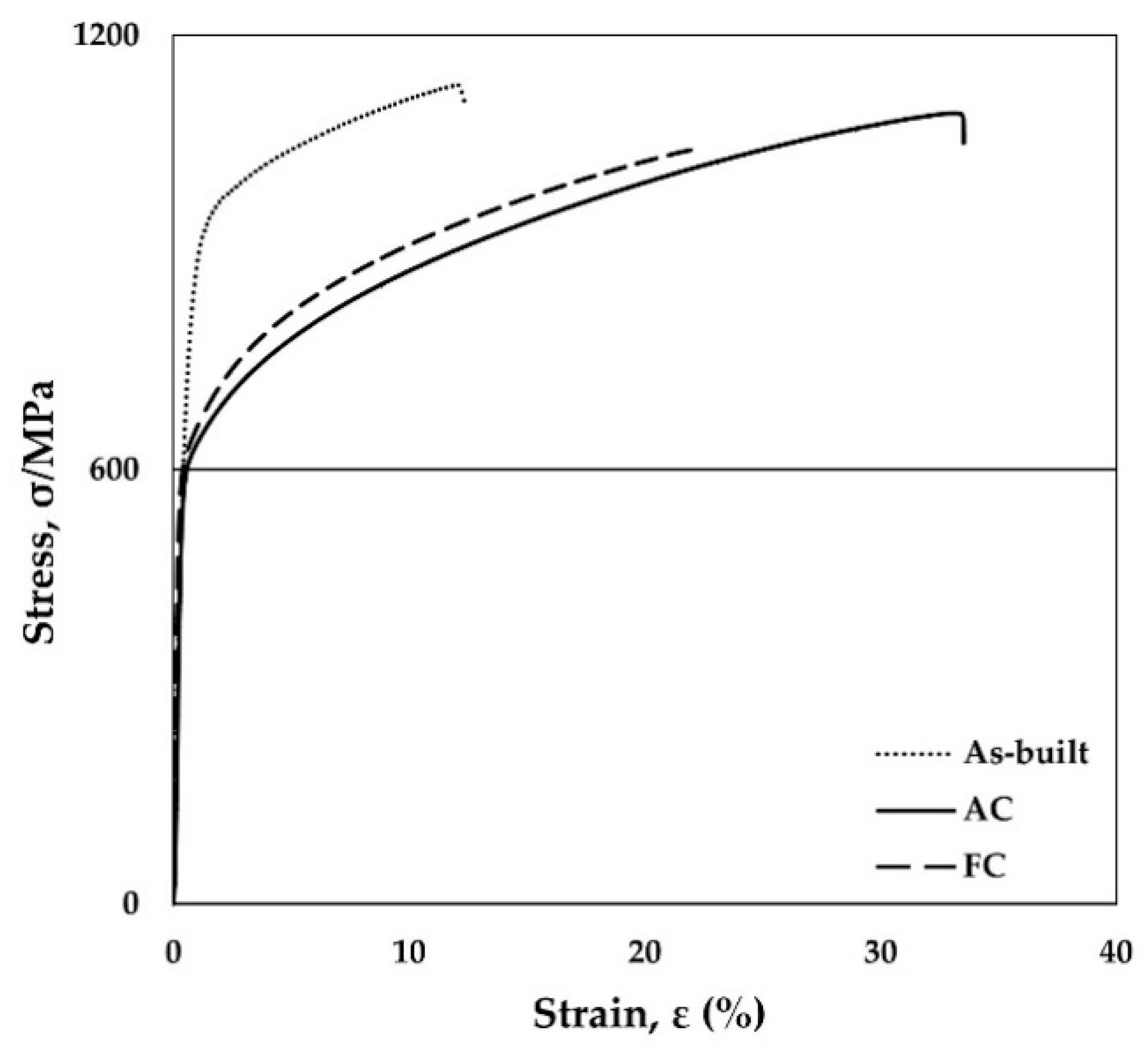
3.1. Mechanical Properties

Table 3 summarizes the mechanical properties of both specimens. The mechanical properties for the sample as-built had 1173 MPa (UTS), 839 MPa (0.2% YS) and 12.3% (Elongation) [16]. Figure 2 shows the typical stress–strain curves. There were no significant differences in the values of UTS and 0.2% YS between the AC and FC samples. The elongation of the AC samples was significantly larger than that of the FC samples. The AC samples had 1.4 times better elongation than the FC. The results of the HV tests are shown in Table 4. There were no significant differences between the AC and FC samples.

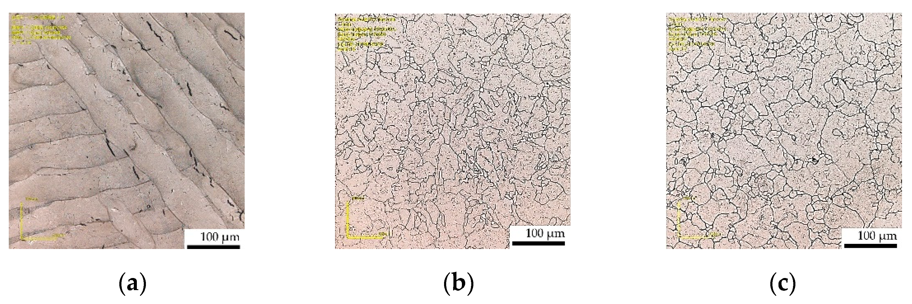
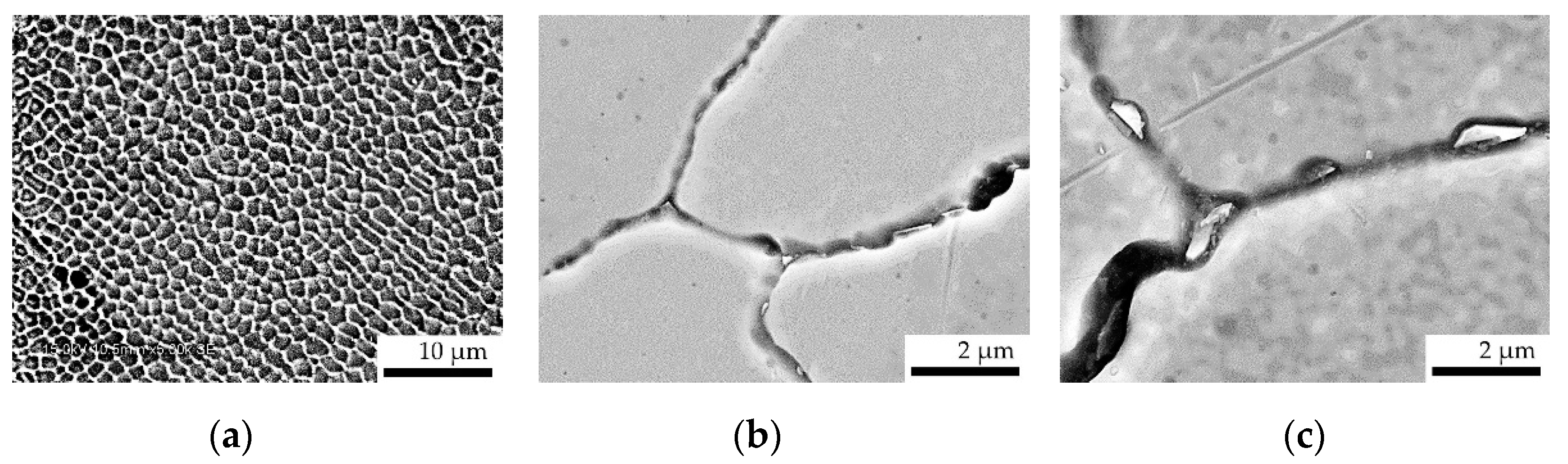
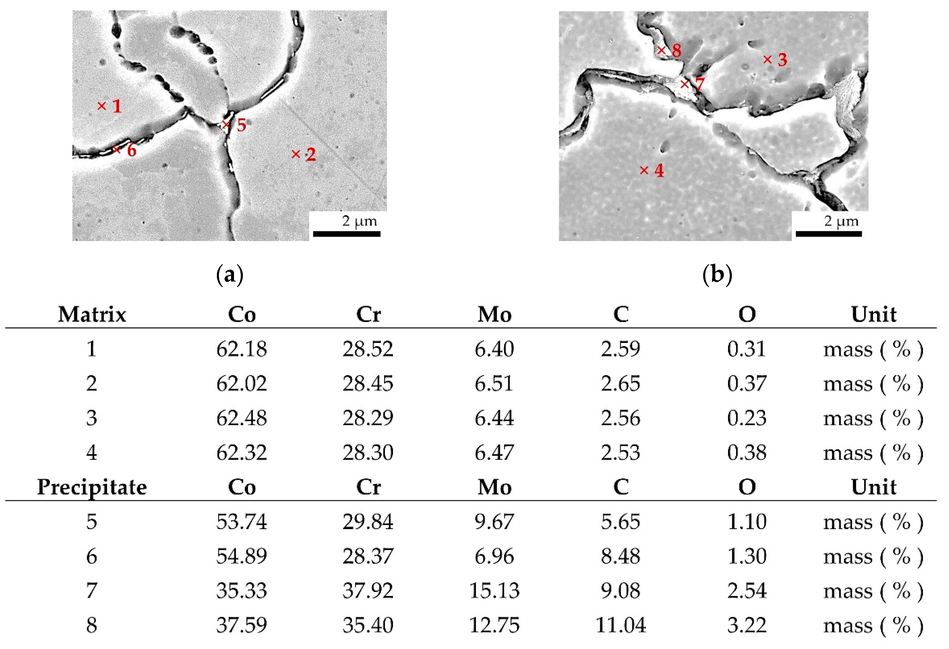
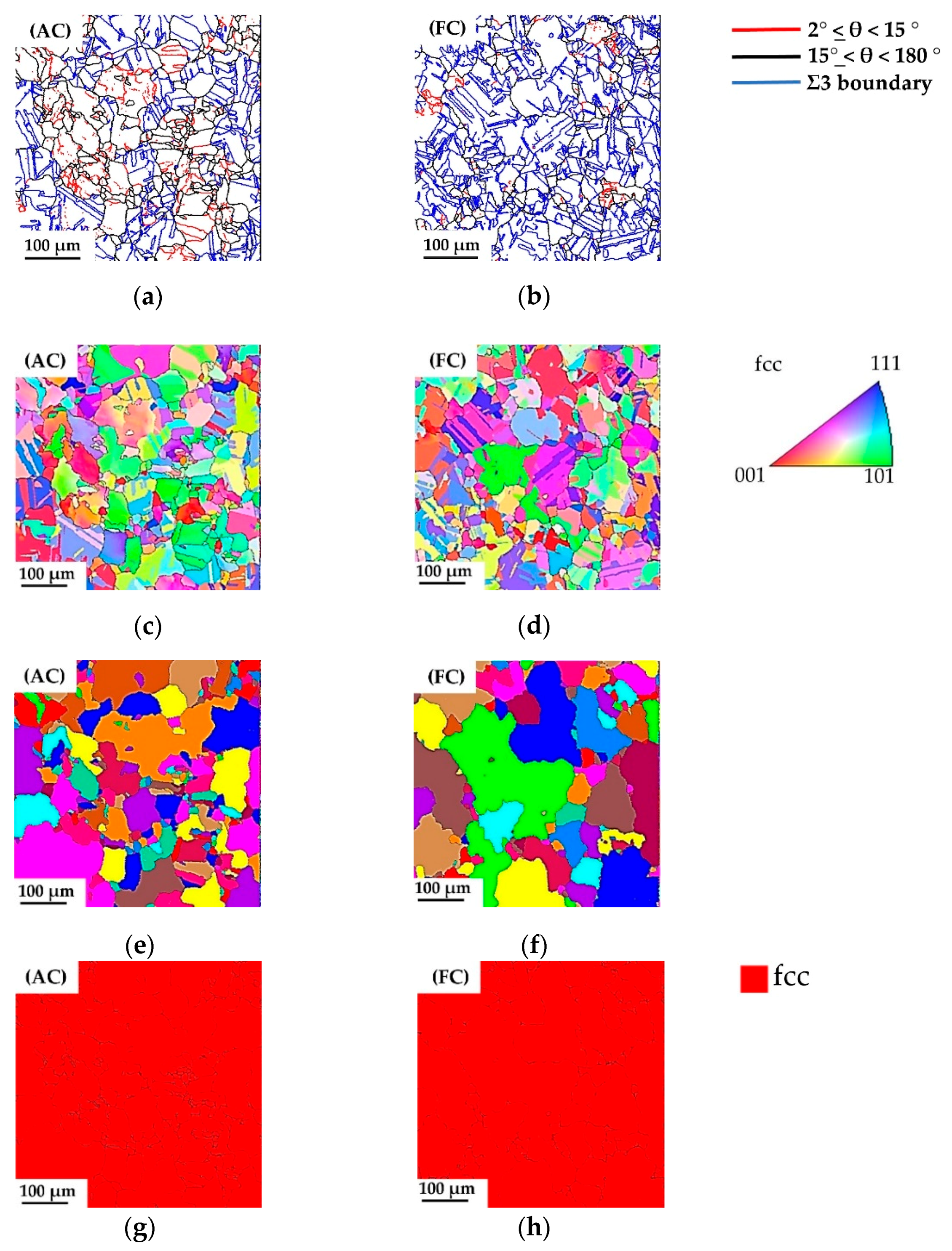
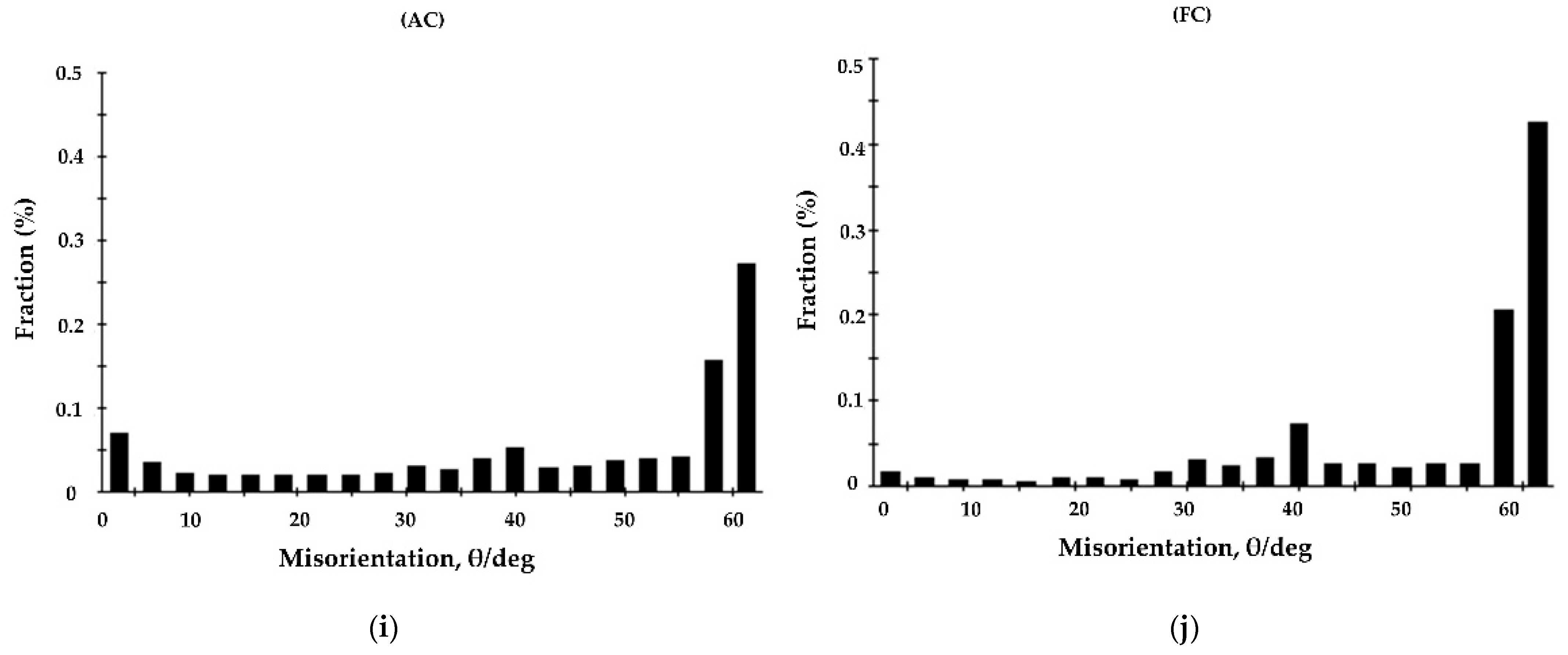
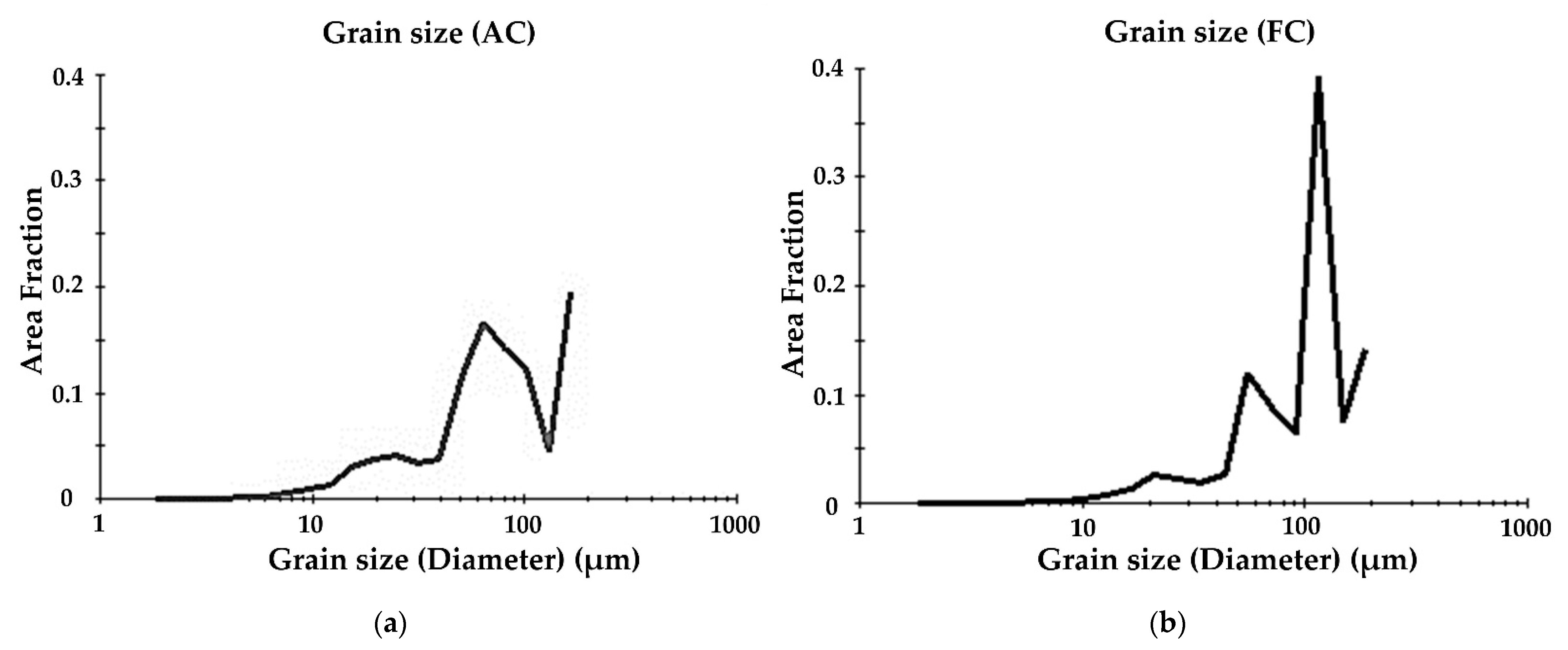
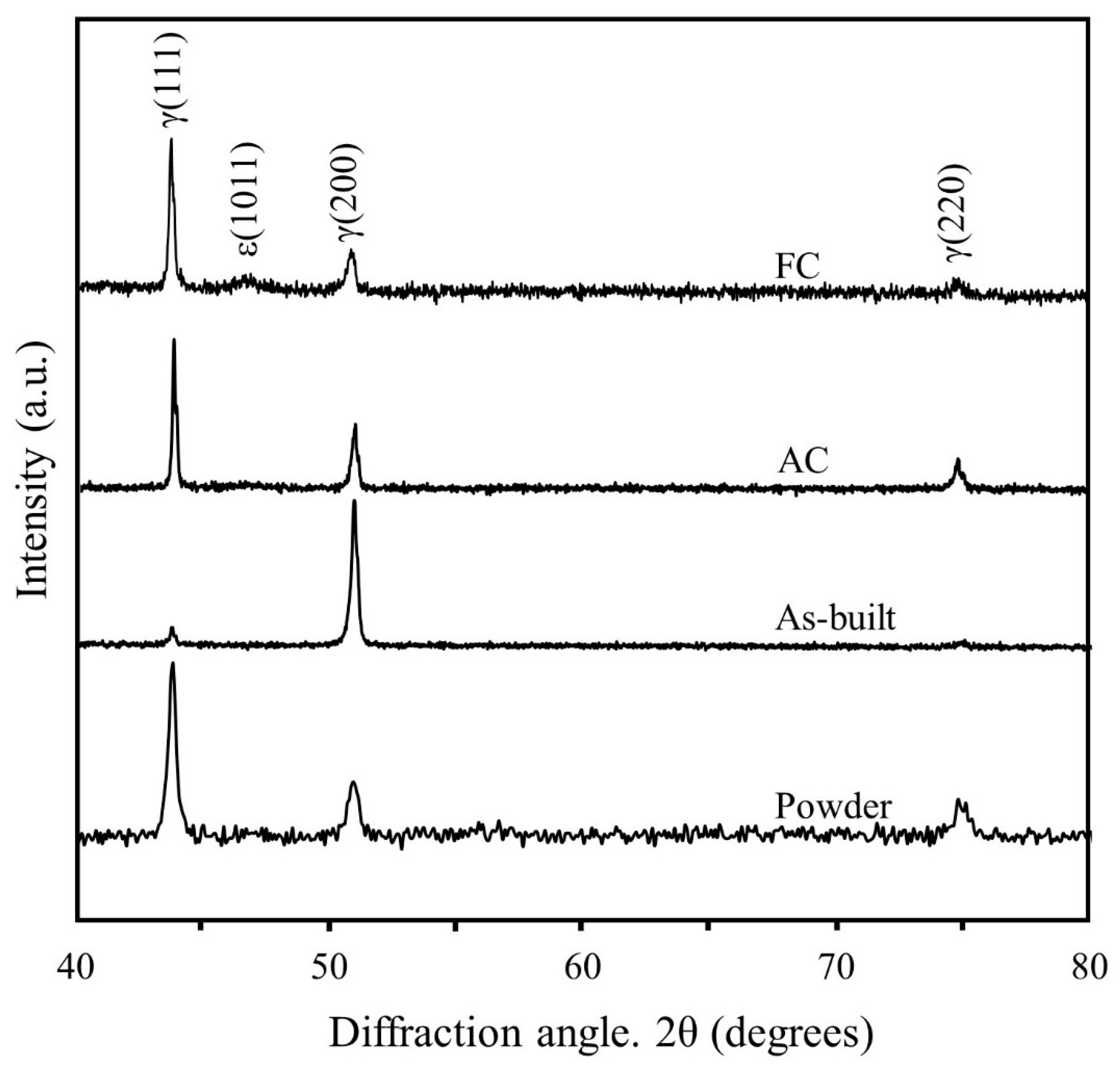
3.2. Microstructure Analysis
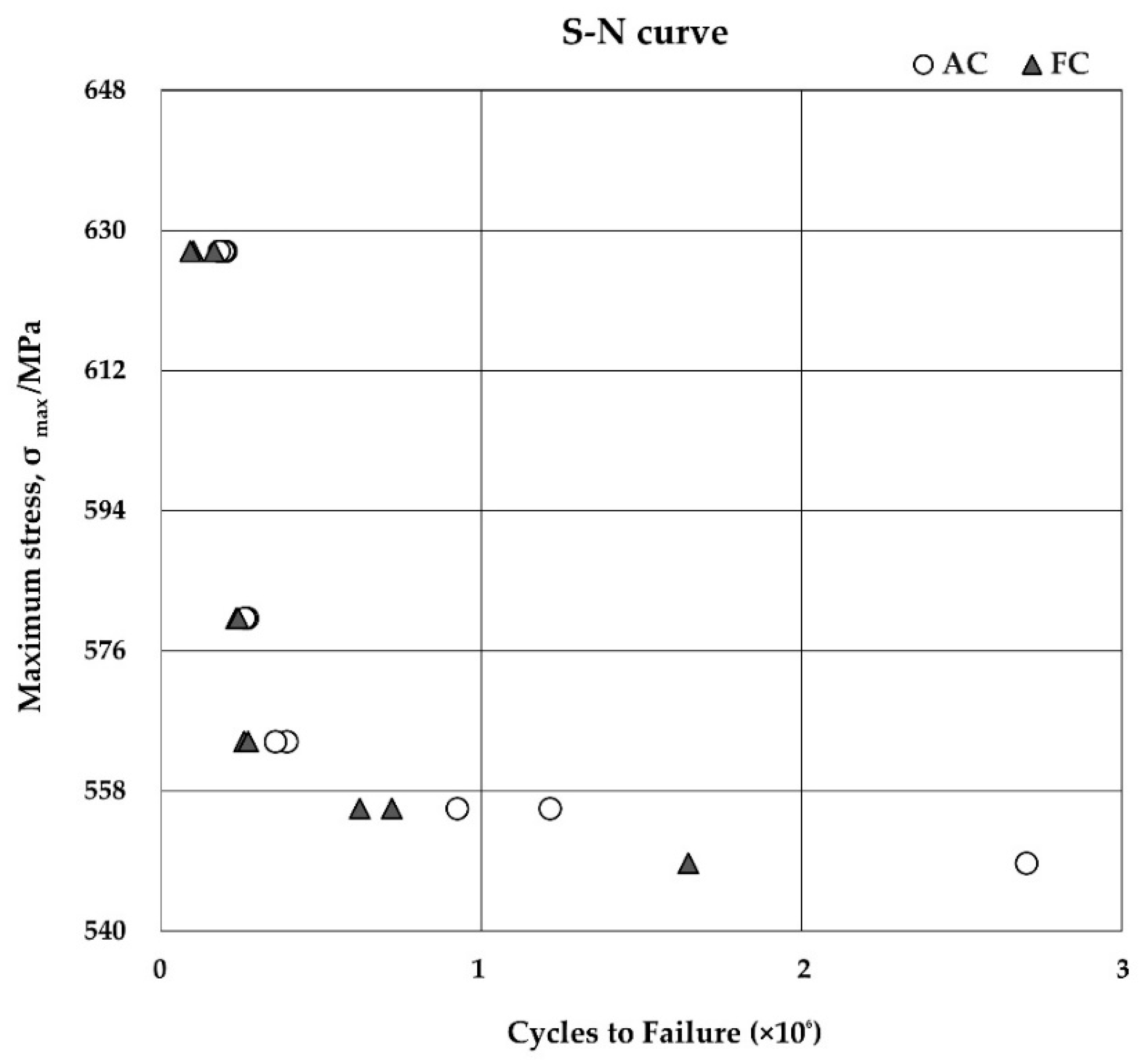
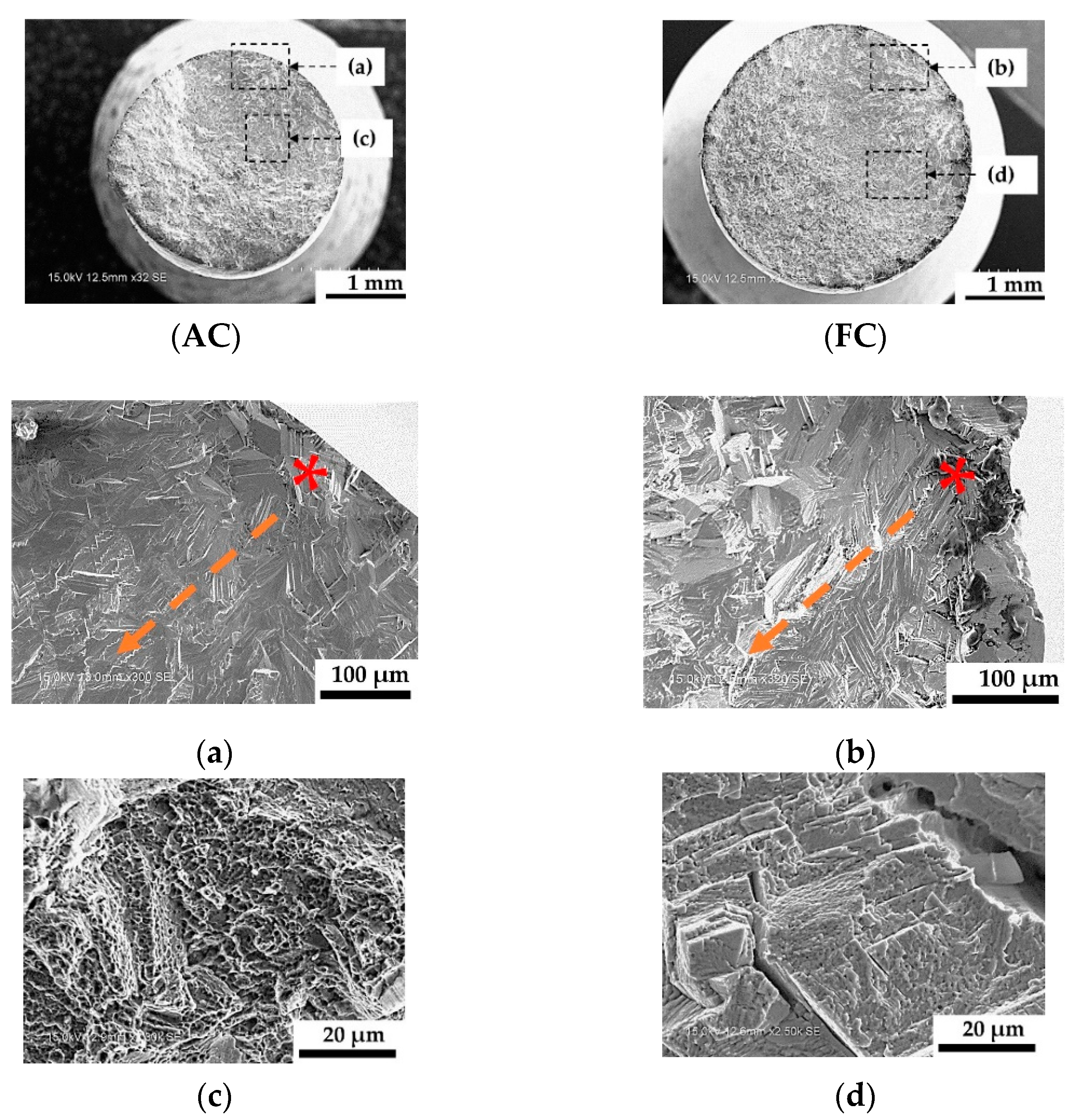
CLSM images of the as-built, AC, and FC samples are shown in Figure 3. The CLSM image of the as-built sample shows that molten pool boundaries were clearly found and numerous fine cellular dendrites were detected in the SEM image of the as-built sample. For both cooling conditions, the CLSM images show homogeneous equiaxed grains with well-defined grain boundaries and no molten pool boundaries. Figure 4 shows the results of the SEM observation. The SEM images for both groups of specimens reveal homogeneous microstructures with precipitates at the grain boundaries. The precipitates of the AC samples were smaller than those of the FC samples. Figure 5 shows that the chemical compositions of the matrices of the AC and FC conditions were identical, with Co being the most abundant, followed by Cr, Mo, C, and O. In the precipitates of the AC and FC samples, the alloy elements appeared to segregate similarly. Compared with the matrices, the alloy elements had higher Mo, C, and O concentrations but lower Co and Cr concentrations. However, the concentrations of Mo and C in the AC samples were lower than those in the FC samples.
The EBSD results for the AC and FC samples are shown in Figure 6. In both conditions, an annealing twin has a Σ3 misorientation of 60°/{111} grain boundaries. High-angle boundaries (HABs) with misorientation angles (MA) greater than 15°, low-angle boundaries (LABs) with misorientation angles between 2° and 15°, and Σ3 boundaries are depicted in red, black and blue lines, respectively, on the grain boundary (GB) maps. Both samples exhibit evenly colored equiaxed grains on the inverse pole figure (IPF) maps. In other studies, annealing twin boundaries were not considered when determining the grain sizes of face-centered cubic γ (FCC) metals [28,29,30], because those boundaries did not seem to be a strong barrier for the pile-up dislocations [28]. Therefore, in this study as well, annealing twin boundaries were not considered as grain boundaries. Figure 7 shows the average distribution of grain size. The grain size was measured using EBSD scan data. The average grain size of the AC samples (84.9 μm) was smaller than that of the FC samples (109.7 μm).
Figure 8 shows the XRD patterns for both groups of samples. The FCC cobalt phase was detected in all samples. In addition, the XRD patterns of the AC and FC were fairly similar to those of the MP1 powder condition. However, a small peak of the ε-HCP phase was also detected. The volume fractions of ε-HCP (wt) calculated by employing the Sage and Guillaud method [25], were present at 16.2% (FC) and 3.9% (AC).

3.3. Fatigue Result

The mean Ra values for each specimen group are listed in Table 5; as is evident, no statistically significant difference (p > 0.01) was present between the groups. Figure 9 shows the S–N curve of the fatigue life of the AC and FC samples. The graph shows that the AC samples had a higher fatigue life than the FC samples did at a stress ratio (R) of 0.1. The lowest cycle count was observed at 627.3 MPa, where the total numbers of cycles for FC and AC were 90,689 and 181,547, respectively. The fatigue life time of the AC sample was 2 times longer than the FC at 627.3 MPa. The largest cycle count was at 548.7 MPa, where the total numbers of cycles for FC and AC were 1,645,574 and 2702.068, respectively. The fatigue life time of AC sample was 1.6 times longer than the FC at 548.7 MPa.
Figure 10 shows the fracture surface of the broken fatigue specimens under both conditions. The fatigue fracture surface had three types of characteristic: (I) microcracks, (II) cleavage fracture patterns, and (III) dimple fracture patterns. Figure 10a,b show the crack initiation sites for the AC and FC samples. In both sets of samples, the crack propagated from the outer surface to the inner region. In the crack propagation region, a mixture of cleavage and dimple features was observed in both the AC and FC samples. However, the number of dimples observed in the AC samples was larger than that in the FC samples. In addition, the FC samples exhibited microcracks.

4. Discussion

The tensile and fatigue test results revealed that the ductility was significantly improved with an increase in the cooling rate. It is well-known that cooling conditions influence microstructures, such as grains and precipitates. In this study, the microstructures observed in the AC samples were finer than those in the FC samples because of a higher cooling rate in the former after the heat treatments. Previous studies have reported the influence of grain size on mechanical properties [9,31,32,33]. Zhuang and Langer [34] examined the impact of grain size changes on the fatigue crack growth rates of as-cast CoCrMo alloy and reported that finer grains yield greater fatigue strengths than coarser grains do. Other studies have also shown improvements in mechanical properties due to finer grains. This phenomenon occurs because a fine-grained microstructure has a large number of grain boundaries, which serve as crack propagation barriers that increase the material’s crack resistance [32,35]. In this study, the finer grains in the AC samples yielded greater fatigue life and elongation compared with the coarser grains in the FC samples.
Precipitate crystal structure, composition, size, and area fraction also significantly affect the mechanical and fatigue properties of an alloy [36,37,38,39]. In a previous study, we confirmed that most of the precipitates observed in SLM-fabricated CoCrMo samples heat-treated for 1 h at 1150 °C exhibited the M (Cr, Mo)23C6 carbide phase [14,16]. The chemical compositions of the precipitates in both the AC and FC samples in this study were similar to the compositions observed in previous studies. However, the AC samples had a lower concentration of Mo and C than the FC samples, as revealed by the coarse M23C6 spectra (Figure 5). The coarse M23C6 carbide precipitates were observed to have a negative impact on the ductility of the alloys [16,40]. In the as-cast condition, carbide precipitation at grain boundaries and in inter-dendritic regions was the primary strengthening mechanism [22,39]. The fine M23C6 carbide particles precipitating in intragranular regions with a homogeneous distribution increased the mechanical strength, which pinned the grain boundaries and inhibited grain growth [22,41]. The coarse carbides at the grain boundaries were detrimental to the ductility of the alloy [36,40]. Although studies on the effect of precipitates in SLM-fabricated CoCrMo on the fatigue life are scarce, our previous study also revealed that blocky carbides developing at grain boundaries reduce fatigue strength [16,18]. In the present study, the larger precipitates at the grain boundaries in the FC samples reduced the ductility more than the precipitates in the AC samples did. Therefore, controlling the size of the precipitate in SLM-fabricated CoCrMo samples is critical for improving the fatigue life.
The presence of two primary phases, ε-HCP and γ–FCC, is widely recognized in Co–Cr–Mo alloys [5,42,43]. The ductility of those alloys increases as the volume percentage of the γ phase increases because this phase has a greater number of independent slip systems than does the ε phase [42,43]. In addition, the ductility of Co–Cr-based alloys is substantially affected by the ε-HCP phase that occurs as a result of athermal, isothermal, and/or strain-induced martensitic transformation [40]. Nonetheless, under normal cooling circumstances, the γ–FCC to ε-HCP change is rare [42]. Slow cooling (FC) leads to the ε -HCP phase, which is more stable at room temperature due to an isothermal transition [43,44,45]. Some researchers reported that a metastable γ–FCC phase at room temperature can be easily stabilized at low temperatures by rapid cooling [45,46]. In this study, the results obtained indicate that the volume fraction of the ε-HCP phase decreases as the cooling rate increases. Therefore, the rapid cooling condition (AC) reduced the transformation of the γ–FCC to ε-HCP and improved the ductility of the alloy.
The morphology of the fracture surfaces also corroborated our findings regarding the mechanical and fatigue properties. In the crack propagation region of the FC samples, highly angular and crystallographic facets were observed, which were similar to the typical cleavage fatigue-fractured characteristics of cast CoCrMo alloy [34]. Therefore, in the FC samples, cleavage cracks could propagate along the {111} planes, which was indicative of brittle fracture [9,16,47,48]. The AC samples showed fracture surfaces with cleavages as well as more dimples than the FC samples did. This indicates an improvement in ductility in the former. These characteristics are congruent with the results regarding the mechanical properties and fatigue test, based on which the AC samples showed a greater increase in ductility than the FC samples.
The findings of this study can serve as a reference for enhancing the fatigue properties of SLM-fabricated CoCrMo alloys and can contribute to improving the durability of biomaterials. Furthermore, this result is significant for dental appliances because it can help in the improvement of the durability of the appliances. However, the number of samples was limited in this study, thus further studies were required to clarify the fatigue limit in AC and FC conditions.

5. Conclusions

In this study, the microstructures, mechanical properties, and fatigue life of CoCrMo alloy samples fabricated through SLM were evaluated after heat treatment for 1 h at 1150 °C under two cooling conditions. The results revealed that increasing the cooling rate enhances the ductility and fatigue life but does not affect the tensile strength or hardness significantly. The AC samples had a smaller average grain size (84.9 µm) than the FC samples (109.7 µm). We believe that smaller grains and precipitates obtained by employing high cooling rates contributed to improving the ductility and fatigue life of the alloy. In future studies, we will apply high-cooling conditions to complex SLM-fabricated biomaterials and investigate their dimensional accuracy.

Author Contributions

Formal analysis, H.H.W.C., H.L.H. and N.K.; Investigation, H.H.W.C., H.L.H. and N.K.; Supervision, A.T., Y.K., T.H. and N.W.; Visualization, A.T. and Y.K.; Writing—original draft, H.H.W.C.; Writing—review and editing, A.T., Y.K., T.H. and N.W. All authors have read and agreed to the published version of the manuscript.

Funding

This research was funded by the Ministry of Education, Culture, Sports, Science, and Technology of Japan, grant numbers 17K17152, 20K10068, 21J40155, and 21K17058; and the Amada Foundation, grant number AF-2019235-C2.

Institutional Review Board Statement

Not applicable.

Informed Consent Statement

Not applicable.

Data Availability Statement

The data that support the findings of this study are available from the corresponding author, upon reasonable request.

Acknowledgments

We sincerely thank the Research Promotion Unit and Research Core Center, Tokyo Medical and Dental University for technical support.

Conflicts of Interest

The authors declare that they have no known competing financial interests or personal relationships that could have appeared to influence the work reported in this paper.

References

  1. De Castro Girão, D.; Béreš, M.; Jardini, A.L.; Filho, R.M.; Silva, C.C.; de Siervo, A.; Gomes de Abreu, H.F.; Araújo, W.S. An assessment of biomedical CoCrMo alloy fabricated by direct metal laser sintering technique for implant applications. Mater. Sci. Eng. C 2020, 107, 110305. [Google Scholar] [CrossRef]
  2. Dos Santos, C.; Habibe, A.F.; Simba, B.G.; Lins, J.F.C.; de Freitas, B.X.; Nunes, C.A. CoCrMo-base Alloys for Dental Applications Obtained by Selective laser melting (SLM) and CAD/CAM Milling. Mater. Res. 2020, 23, 1–6. [Google Scholar] [CrossRef]
  3. Shiri, S.; Zhang, C.; Odeshi, A.; Yang, Q. Growth and characterization of tantalum multilayer thin fi lms on CoCrMo alloy for orthopedic implant applications. Thin Solid Film. 2018, 645, 405–408. [Google Scholar] [CrossRef]
  4. Yoda, K.; Suyalatu; Takaichi, A.; Nomura, N.; Tsutsumi, Y.; Doi, H.; Kurosu, S.; Chiba, A.; Igarashi, Y.; Hanawa, T. Effects of chromium and nitrogen content on the microstructures and mechanical properties of as-cast Co-Cr-Mo alloys for dental applications. Acta Biomater. 2012, 8, 2856–2862. [Google Scholar] [CrossRef] [PubMed]
  5. Wang, Z.; Tang, S.Y.; Scudino, S.; Ivanov, Y.P.; Qu, R.T.; Wang, D.; Yang, C.; Zhang, W.; Greer, A.L.; Eckert, J.; et al. Additive manufacturing of a martensitic Co-Cr-Mo alloy: Towards circumventing the strength—Ductility trade-off. Addit. Manuf. 2021, 37, 1–14. [Google Scholar] [CrossRef]
  6. Wang, Z.; Xie, M.; Li, Y.; Zhang, W.; Yang, C.; Kollo, L.; Eckert, J.; Prashanth, K.G. Premature failure of an additively manufactured material. NPG Asia Mater. 2020. [Google Scholar] [CrossRef]
  7. Oliveira, J.P.; LaLonde, A.D.; Ma, J. Processing parameters in laser powder bed fusion metal additive manufacturing. Mater. Des. 2020, 193, 1–12. [Google Scholar] [CrossRef]
  8. Song, C.; Yang, Y.; Wang, Y.; Wang, D.; Yu, J. Research on rapid manufacturing of CoCrMo alloy femoral component based on selective laser melting. Int. J. Adv. Manuf. Technol. 2014, 75, 445–453. [Google Scholar] [CrossRef]
  9. Takaichi, A.; Nakamoto, T.; Joko, N.; Nomura, N. Microstructures and mechanical properties of Co-29Cr-6Mo alloy fabricated by selective laser melting process for dental applications. J. Mech. Behav. Biomed. Mater. 2013, 21, 67–76. [Google Scholar] [CrossRef] [PubMed]
  10. Kajima, Y.; Takaichi, A.; Nakamoto, T.; Kimura, T.; Yogo, Y.; Ashida, M.; Doi, H.; Nomura, N.; Takahashi, H.; Hanawa, T.; et al. Fatigue strength of Co-Cr-Mo alloy clasps prepared by selective laser melting. J. Mech. Behav. Biomed. Mater. 2016, 59, 446–458. [Google Scholar] [CrossRef] [PubMed]
  11. Li, H.; Wang, M.; Lou, D.; Xia, W.; Fang, X. Microstructural features of biomedical cobalt–chromium–molybdenum (CoCrMo) alloy from powder bed fusion to aging heat treatment. J. Mater. Sci. Technol. 2020, 45, 146–156. [Google Scholar] [CrossRef]
  12. Roudnicka, M.; Bigas, J.; Molnarova, O.; Palousek, D.; Vojtech, D. Different response of cast and 3d-printed co-cr-mo alloy to heat treatment: A thorough microstructure characterization. Metals 2021, 11, 687. [Google Scholar] [CrossRef]
  13. Wei, W.; Zhou, Y.; Sun, Q.; Li, N.; Yan, J.; Li, H.; Liu, W.; Huang, C. Microstructures and Mechanical Properties of Dental Co-Cr-Mo-W Alloys Fabricated by Selective Laser Melting at Different Subsequent Heat Treatment Temperatures. Metall. Mater. Trans. A Phys. Metall. Mater. Sci. 2020, 51, 3205–3214. [Google Scholar] [CrossRef]
  14. Takaichi, A.; Kajima, Y.; Kittikundecha, N.; Htat, H.L.; Wai Cho, H.H.; Hanawa, T.; Yoneyama, T.; Wakabayashi, N. Effect of heat treatment on the anisotropic microstructural and mechanical properties of Co–Cr–Mo alloys produced by selective laser melting. J. Mech. Behav. Biomed. Mater. 2020, 102. [Google Scholar] [CrossRef]
  15. Liu, Y.; Yang, Y.; Wang, D. A study on the residual stress during selective laser melting (SLM) of metallic powder. Int. J. Adv. Manuf. Technol. 2016, 87, 647–656. [Google Scholar] [CrossRef]
  16. Kajima, Y.; Takaichi, A.; Kittikundecha, N.; Nakamoto, T.; Kimura, T.; Nomura, N.; Kawasaki, A.; Hanawa, T.; Takahashi, H.; Wakabayashi, N. Effect of heat-treatment temperature on microstructures and mechanical properties of Co–Cr–Mo alloys fabricated by selective laser melting. Mater. Sci. Eng. A 2018, 726, 21–31. [Google Scholar] [CrossRef]
  17. Seki, E.; Kajima, Y.; Takaichi, A.; Kittikundecha, N.; Cho, H.H.W.; Htat, H.L.; Doi, H.; Hanawa, T.; Wakabayashi, N. Effect of heat treatment on the microstructure and fatigue strength of CoCrMo alloys fabricated by selective laser melting. Mater. Lett. 2019, 245, 53–56. [Google Scholar] [CrossRef]
  18. Kittikundecha, N.; Kajima, Y.; Takaichi, A.; Wai Cho, H.H.; Htat, H.L.; Doi, H.; Takahashi, H.; Hanawa, T.; Wakabayashi, N. Fatigue properties of removable partial denture clasps fabricated by selective laser melting followed by heat treatment. J. Mech. Behav. Biomed. Mater. 2019, 98, 79–89. [Google Scholar] [CrossRef] [PubMed]
  19. Razavi, S.M.J.; Avanzini, A.; Cornacchia, G.; Giorleo, L.; Berto, F. Effect of heat treatment on fatigue behavior of as-built notched Co-Cr-Mo parts produced by Selective Laser Melting. Int. J. Fatigue 2021, 142. [Google Scholar] [CrossRef]
  20. Cui, X.; Zhang, S.; Wang, C.; Zhang, C.H.; Chen, J.; Zhang, J.B. Effects of stress-relief heat treatment on the microstructure and fatigue property of a laser additive manufactured 12CrNi2 low alloy steel. Mater. Sci. Eng. A 2020, 791. [Google Scholar] [CrossRef]
  21. Elangeswaran, C.; Cutolo, A.; Muralidharan, G.K.; Vanmeensel, K.; Van Hooreweder, B. Microstructural analysis and fatigue crack initiation modelling of additively manufactured 316L after different heat treatments. Mater. Des. 2020, 194. [Google Scholar] [CrossRef]
  22. Dong, X.; Zhou, Y.; Sun, Q.; Qu, Y.; Shi, H.; Liu, W.; Peng, H.; Zhang, B.; Xu, S.; Yan, J.; et al. Fatigue behavior of biomedical Co–Cr–Mo–W alloy fabricated by selective laser melting. Mater. Sci. Eng. A 2020, 795, 140000. [Google Scholar] [CrossRef]
  23. Lu, Y.; Wu, S.; Gan, Y.; Zhang, S.; Guo, S.; Lin, J.; Lin, J. Microstructure, mechanical property and metal release of As-SLM CoCrW alloy under different solution treatment conditions. J. Mech. Behav. Biomed. Mater. 2016, 55, 179–190. [Google Scholar] [CrossRef]
  24. Mp, C.C.; Performance, M.P.; Original, E.O.S.; Set, P.; Surface, M.P. Material data sheet EOS CobaltChrome MP1. Mater. Data Sheet Tech. Data 2011, 49, 1–6. [Google Scholar]
  25. Sage, M.; Guillaud, C. Méthode d’analyse quantitative des variétés allotropiques du cobalt par les rayons X. Rev. Metall. 1950, 47, 139–145. [Google Scholar] [CrossRef]
  26. Japanese Industrial Standards Committee. Test method for notch sensitivity and fatigue crack growth properties of metallic biomaterials. JIS T 0310 2009, 9. [Google Scholar]
  27. Okazaki, Y. Comparison of fatigue properties and fatigue crack growth rates of various implantable metals. Materials 2012, 5, 2981–3005. [Google Scholar] [CrossRef] [Green Version]
  28. Nakanishi, K.; Suzuki, H. Analysis of the grain size dependence of the yield stress in copper-aluminum and copper-nickel alloys. Trans. Jpn. Inst. Met. 1974, 15, 435–440. [Google Scholar] [CrossRef] [Green Version]
  29. Schneider, M.; Werner, F.; Langenkämper, D.; Reinhart, C. Effect of Temperature and Texture on Hall—Petch Strengthening by Grain and Annealing Twin Boundaries in the MnFeNi Medium-Entropy Alloy. Metals 2019, 1, 84. [Google Scholar] [CrossRef] [Green Version]
  30. Slone, C.E.; Larosa, C.R.; Zenk, C.H.; George, E.P.; Ghazisaeidi, M.; Mills, M.J. Scripta Materialia Deactivating deformation twinning in medium-entropy CrCoNi with small additions of aluminum and titanium. Scr. Mater. 2020, 178, 295–300. [Google Scholar] [CrossRef]
  31. Kaiser, R.; Williamson, K.; O’Brien, C.; Ramirez-Garcia, S.; Browne, D.J. The influence of cooling conditions on grain size, secondary phase precipitates and mechanical properties of biomedical alloy specimens produced by investment casting. J. Mech. Behav. Biomed. Mater. 2013, 24, 53–63. [Google Scholar] [CrossRef] [PubMed]
  32. Van Hooreweder, B.; Moens, D.; Boonen, R.; Kruth, J.P.; Sas, P. Analysis of fracture toughness and crack propagation of Ti6Al4V produced by selective laser melting. Adv. Eng. Mater. 2012, 14, 92–97. [Google Scholar] [CrossRef]
  33. Yadollahi, A.; Shamsaei, N.; Thompson, S.M.; Seely, D.W. Effects of process time interval and heat treatment on the mechanical and microstructural properties of direct laser deposited 316L stainless steel. Mater. Sci. Eng. A 2015, 644, 171–183. [Google Scholar] [CrossRef]
  34. Zhuang, L.Z.; Langer, E.W. Study on fatigue threshold behaviour and fatigue crack propagation in a cast Co-Cr-Mo alloy used for surgical implants. Fatigue Fract. Eng. Mater. Struct. 1989, 12, 283–293. [Google Scholar] [CrossRef]
  35. Aboulkhair, N.T.; Maskery, I.; Tuck, C.; Ashcroft, I.; Everitt, N.M. Improving the fatigue behaviour of a selectively laser melted aluminium alloy: Influence of heat treatment and surface quality. Mater. Des. 2016, 104, 174–182. [Google Scholar] [CrossRef]
  36. Vasudevan, A.K.; Doherty, R.D. Grain boundary ductile fracture in precipitation hardened aluminum alloys. Acta Metall. 1987, 35, 1193–1219. [Google Scholar] [CrossRef]
  37. Song, C.B.; Park, H.B.; Seong, H.G.; Lopez, H.F. Development of athermal ε-martensite in atomized Co–Cr–Mo–C implant alloy powders. Acta Biomater. 2006, 2, 685–691. [Google Scholar] [CrossRef]
  38. Yamanaka, K.; Mori, M.; Chiba, A. Mechanical properties of as-forged Ni-free Co-29Cr-6Mo alloys with ultrafine-grained microstructure. Mater. Sci. Eng. A 2011, 528, 5961–5966. [Google Scholar] [CrossRef]
  39. Dolgov, N.A.; Tsanka, D.; Dzhendo, D.; Pavlova, D.; Simov, M. Mechanical properties of dental Co-Cr alloys fabricated via casting and selective laser melting. Mater. Sci. Non Equilib. Phase Transform. 2016, 2, 3–7. [Google Scholar]
  40. Yamanaka, K.; Mori, M.; Chiba, A. Effects of carbon concentration on microstructure and mechanical properties of as-cast nickel-free Co-28Cr-9W-based dental alloys. Mater. Sci. Eng. C 2014, 40, 127–134. [Google Scholar] [CrossRef]
  41. Santecchia, E.; Gatto, A.; Bassoli, E.; Denti, L.; Rutkowski, B.; Mengucci, P.; Barucca, G. Precipitates formation and evolution in a Co-based alloy produced by powder bed fusion. J. Alloy. Compd. 2019, 797, 652–658. [Google Scholar] [CrossRef]
  42. Rajan, K.; Vander Sande, J.B. Room temperature strengthening mechanisms in a Co-Cr-Mo-C alloy. J. Mater. Sci. 1982, 17, 769–778. [Google Scholar] [CrossRef]
  43. Kurosu, S.; Matsumoto, H.; Chiba, A. Isothermal phase transformation in biomedical Co-29Cr-6Mo alloy without addition of carbon or nitrogen. Metall. Mater. Trans. A Phys. Metall. Mater. Sci. 2010, 41, 2613–2625. [Google Scholar] [CrossRef]
  44. Cai, S.; Daymond, M.R.; Ren, Y. Materials Science & Engineering A Stress induced martensite transformation in Co-28Cr-6Mo alloy during room temperature deformation. Mater. Sci. Eng. A 2013, 580, 209–216. [Google Scholar] [CrossRef]
  45. Bére, M.; Silva, C.C.; Sarvezuk, P.W.C.; Wu, L.; Antunes, L.H.M.; Jardini, A.L.; Feitosa, A.L.M.; Žilková, J.; De Abreu, H.F.G.; Filho, R.M. Materials Science & Engineering A Mechanical and phase transformation behaviour of biomedical Co-Cr-Mo alloy fabricated by direct metal laser sintering. Mater. Sci. Eng. A 2018, 714, 36–42. [Google Scholar] [CrossRef]
  46. Olson, G.B.; Cohen, M. A mechanism for the strain-induced nucleation of martensitic transformations. J. Less Common Met. 1972, 28, 107–118. [Google Scholar] [CrossRef]
  47. AlMangour, B.; Luqman, M.; Grzesiak, D.; Al-Harbi, H.; Ijaz, F. Effect of processing parameters on the microstructure and mechanical properties of Co–Cr–Mo alloy fabricated by selective laser melting. Mater. Sci. Eng. A 2020, 792, 139456. [Google Scholar] [CrossRef]
  48. Lu, Y.; Wu, S.; Gan, Y.; Li, J.; Zhao, C.; Zhuo, D.; Lin, J. Investigation on the microstructure, mechanical property and corrosion behavior of the selective laser melted CoCrW alloy for dental application. Mater. Sci. Eng. C 2015, 49, 517–525. [Google Scholar] [CrossRef]
Figure 1. Arrangement for the dumbbell-shaped specimen on the base plate. The blue plane shows the direction of the cutting plane for microstructural observations.
Metals 11 01005 g001
Figure 2. Typical stress and strain curves for the as-built sample as a reference, adapted from [16], AC and FC samples.
Metals 11 01005 g002
Figure 3. CLSM images of the (a) as-built, (b) AC and (c) FC samples horizontally cross section to the BD.
Metals 11 01005 g003
Figure 4. Scanning electron microscopy (SEM) images of the precipitates of the (a) as-built, (b) AC and (c) FC samples.
Metals 11 01005 g004
Figure 5. SEM images and energy-dispersive X-ray spectroscopy (EDS) result of the matrices and precipitates of the (a) AC and (b) FC.
Metals 11 01005 g005
Figure 6. Result of EBSD studies of the AC and FC samples: (a,b) GB, (c,d) IPF maps, (e,f) grain maps, (g,h) phase maps, and (i,j) MA.
Metals 11 01005 g006aMetals 11 01005 g006b
Figure 7. Grain size distribution of the (a) AC and (b) FC samples.
Metals 11 01005 g007
Figure 8. X-ray diffraction (XRD) patterns: powder as a reference, adapted from ref. [18], as-built selective laser melting (SLM) specimens as a reference, adapted from ref. [18], AC sample, and FC sample.
Metals 11 01005 g008
Figure 9. S–N curve for the fatigue result of the AC and FC samples.
Metals 11 01005 g009
Figure 10. Surface morphology of fractures in AC and FC samples: (a,b) magnified views of the crack initial point, (c,d) magnified views of the fracture propagation region. * denotes the initial crack and the orange arrow shows the direction of crack propagation.
Metals 11 01005 g010
Table 1. Chemical compositions of CoCrMo alloy powder (MP1) in units of mass (%).
CoCrMoSiMnFeCNi
MP160–6526–305–7<1.0<1.0<0.75<0.16<0.1
Table 2. Fatigue loads and number of specimens (N) for the test.
Stress Ratio (R)Maximum Stress (MPa)Minimum Stress (MPa)Number of Air Cooling SamplesNumber of Furnace Cooling Samples
0.1627.3335.4833
0.1580.1538.1422
0.1564.3038.0322
0.1555.7037.0322
0.1548.7040.5711
Table 3. Statistical summary of the mechanical properties of the AC and FC conditions. (* indicates statistical significance, p < 0.01).
Mechanical PropertiesACFC
UTS (MPa)11181110
0.2%YS (MPa)622.87635.30
Elongation (%)33.11 *23.37
Table 4. The AC and FC samples’ Vickers hardness (HV) values. No significant difference between values labeled with similar letters (p > 0.01).
GroupMean (HV)Standard Deviation
As-built536.80 a7.12
AC365.30 b4.32
FC371.98 b3.92
Table 5. Surface roughness (Ra) values of the AC and FC samples. No significant difference between values labeled with similar letters (p > 0.01).
GroupMean (μm)Standard Deviation
AC0.27 a0.10
FC0.31 a0.85
Publisher’s Note: MDPI stays neutral with regard to jurisdictional claims in published maps and institutional affiliations.

