Springback Prediction of Dieless Forming of AZM120 Sheet Metal Based on Constitutive Model


1
College of Mechanical Engineering, Yangzhou University, Yangzhou 225127, China
2
Jiangsu Yawei Machine-Tool Co., Ltd., Yangzhou 225200, China
*
Author to whom correspondence should be addressed.
Metals 2020, 10(6), 780; https://doi.org/10.3390/met10060780
Submission received: 29 April 2020
/
Revised: 8 June 2020
/
Accepted: 8 June 2020
/
Published: 11 June 2020
Abstract
:Springback control is a key issue of the sheet-metal-forming process. In this paper, the mechanism of sheet-metal-forming along the folding trajectory of the computer numerical control (CNC) four-side automatic panel bender was studied, based on the bend-forming springback compensation theory of the power function material model. Firstly, the mechanical property of AZM120 sheet metal standard samples was tested. Then, a theoretical model of springback compensation under plane strain conditions was built, based on the constitutive relationship of the elastic or the elastic-plastic power hardening material. In addition, a sheet-metal-forming trajectory model was designed for sheet metal bending using the vector method. Finally, a laser tracker was used to acquire the folding trajectory, and then the reliability of the trajectory model was verified. On this basis, the influences of geometric and process parameters, such as sheet thickness, forming angle, and bending radius in springback control, were studied according to the theoretical formula and verified by experiments. The proposed method is generally applicable to operation conditions where the bending radius ranges between 1.5 and 6.0 mm and plate thickness ranges from 0.8 to 2.5 mm, and the achieved overall accuracy was more than 89%.
1. Introduction
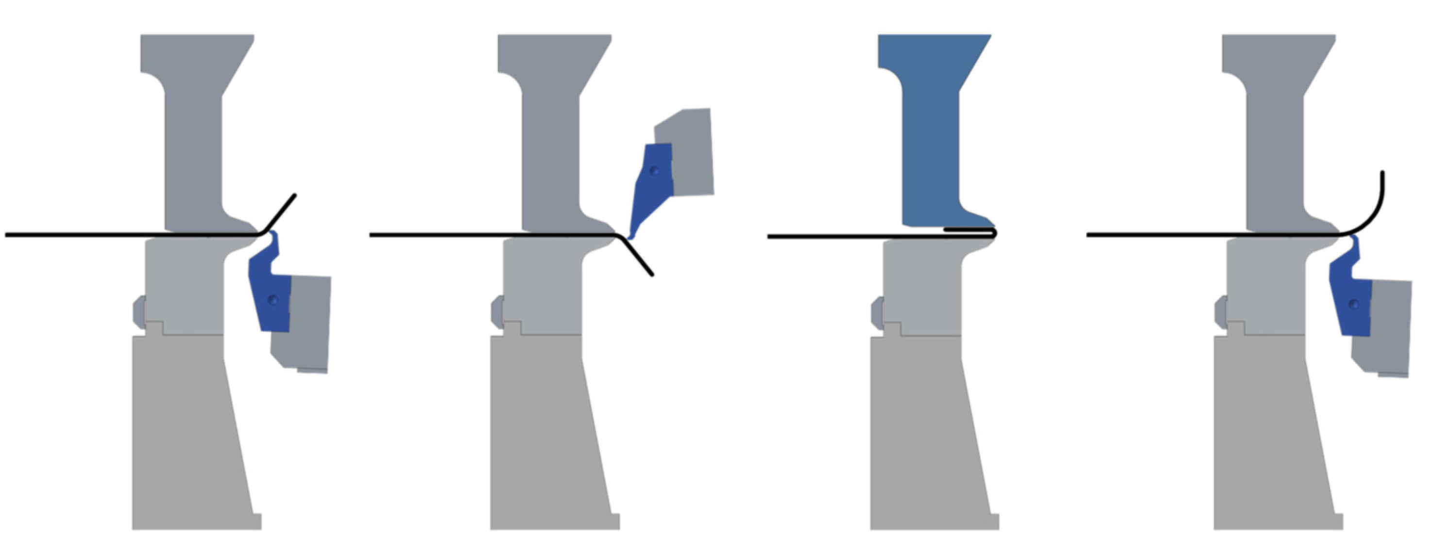
Sheet-metal-forming nowadays is widely used in the aeronautical, automotive, mechanical and construction industries [1]. With the increasingly fast upgrading of products in the field of manufacturing, the demand is more prominent for product diversification and personalization. The manufacture of sheet metal is developing towards high flexibility and efficiency, and small batch and flexible-surface-forming technology [2]. In traditional die-stamping production, the die design cycle is longer and the manufacturing cost is higher, so it is urgent to develop a technology for forming surface-curved parts with high flexibility and precision in the field of plastic processing. The high-speed bending technology of the automatic panel bender is an efficient and flexible digital forming technology [3,4,5]. The computer numerical control (CNC) automatic panel bender has the advantages of a short operation path, no overall turnover of workpiece, fast feeding speed, etc. It can realize complete automatic production, from lean manufacturing to mass production. The typical folding types are shown in Figure 1, which shows forward bend, negative bend, re-flattening, and large-arc bend, respectively, from left to right.
Springback is a prominent feature of the sheet-metal-forming process, which highly affects the accuracy of metallic curved parts [6]. Hill [7] first established a relatively accurate theoretical model of elastic-plastic bending under plane strains. This theoretical model takes transverse stress and neutral layer movement into consideration. According to the Von-Mises yielding criterion and nonlinear kinematic hardening theory, Morestin et al. [8] re-established the final shape after springback by using the curvature radius after releasing residual stress. Zhang et al. [9] developed the springback analytical model of U-shaped bent parts according to Hill, yielding the criterion and plane strain condition. Parsa et al. [10] proposed the analytical calculation formula to predict the curved surface springback of hyperboloids, studied the influences of initial thickness, curvature radius, tension, and other factors upon springback, and verified the accuracy of the springback prediction formula with experiments and other methods. Using the kinematic hardening material model and Yoshida-Uemori (YU) model, Hassen et al. [11] put forward a strategy for the reduction of springback based on variable blankholder force. Jung et al. [12] formulated an elastoplastic material constitutive model to account for the evolution of the anisotropy of a dual-phase steel. The combined isotropic-kinematic hardening model was modified and the influence of anisotropy on springback prediction accuracy was analyzed. In addition, based on explicit and implicit finite element analysis, Hu et al. [13] developed a method to predict the springback and generate compensated forming trajectories, and Zhang et al. [14] proposed an iterative method of tool compensation based on the displacement adjustment method. Li et al. [15] established a mathematical model of an involute curve roller track with forming clearance compensation. Combined with the mechanism of stress relaxation, Jin et al. [16] established springback and residual relative curvature equations of springback. The springback and residual deflection models were provided.
At present, there are several methods to control springback, such as die compensation, pressure correction, and forming process optimization. Moreover, due to the processing characteristics of dieless forming for the automatic panel bender, higher technical requirements are necessary for springback control and guarantee of accuracy, so it is of great significance to study the springback of slightly constrained panels free of die flanging.
2. Materials and Methods
2.1. Material Performance Test of AZM120
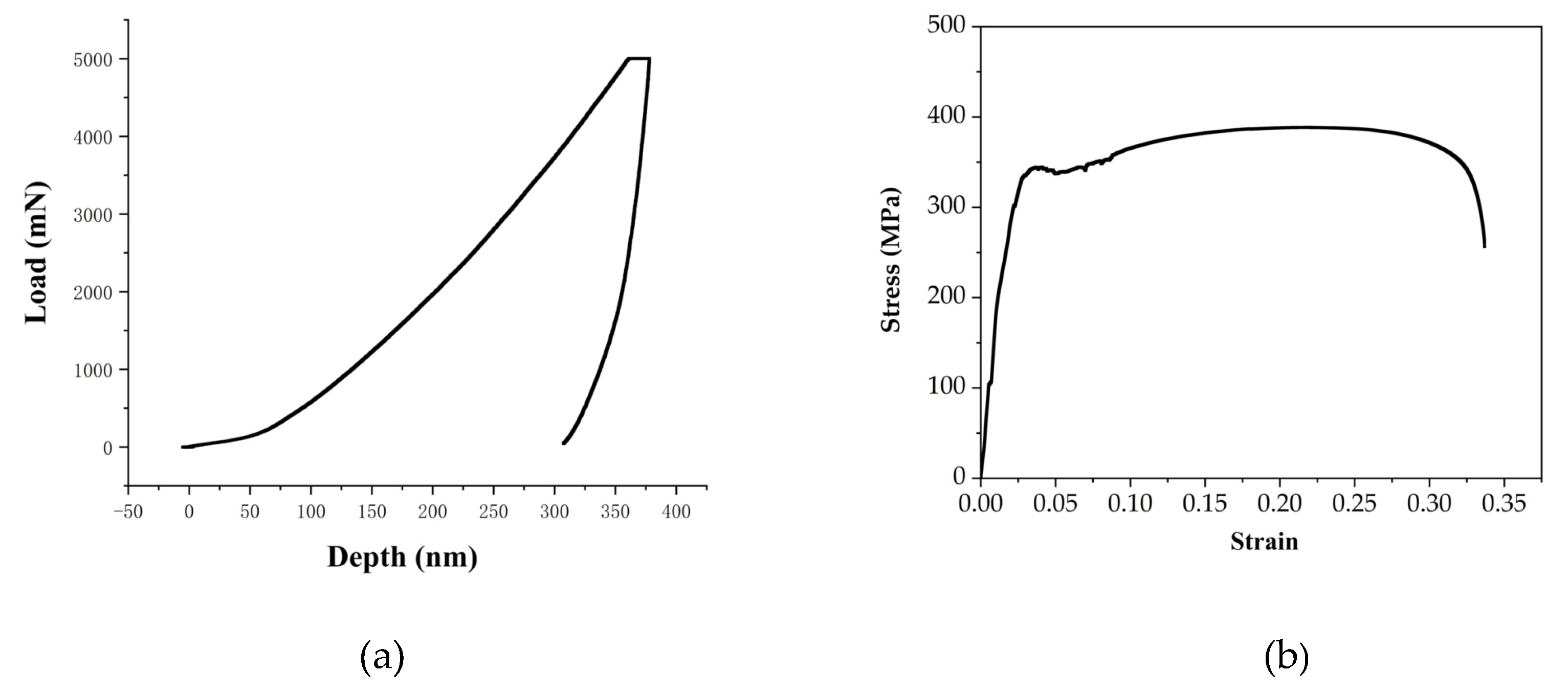
The mechanical property test is an important method to evaluate metal materials [17]. The AZM120 super galum, which is coated with a 55% aluminium–zinc alloy on its surface while applying structural steel as its substrate, is taken as the study object of this paper. By testing the properties of AZM120 plates in a tensile test and nanoindentation test, the stress-strain curve and the load-displacement curve of the material were obtained, respectively, and the yield strength, Poisson’s ratio, hardening index, and elastic modulus of the material were obtained, which provided data for the fitting of the power function curve.
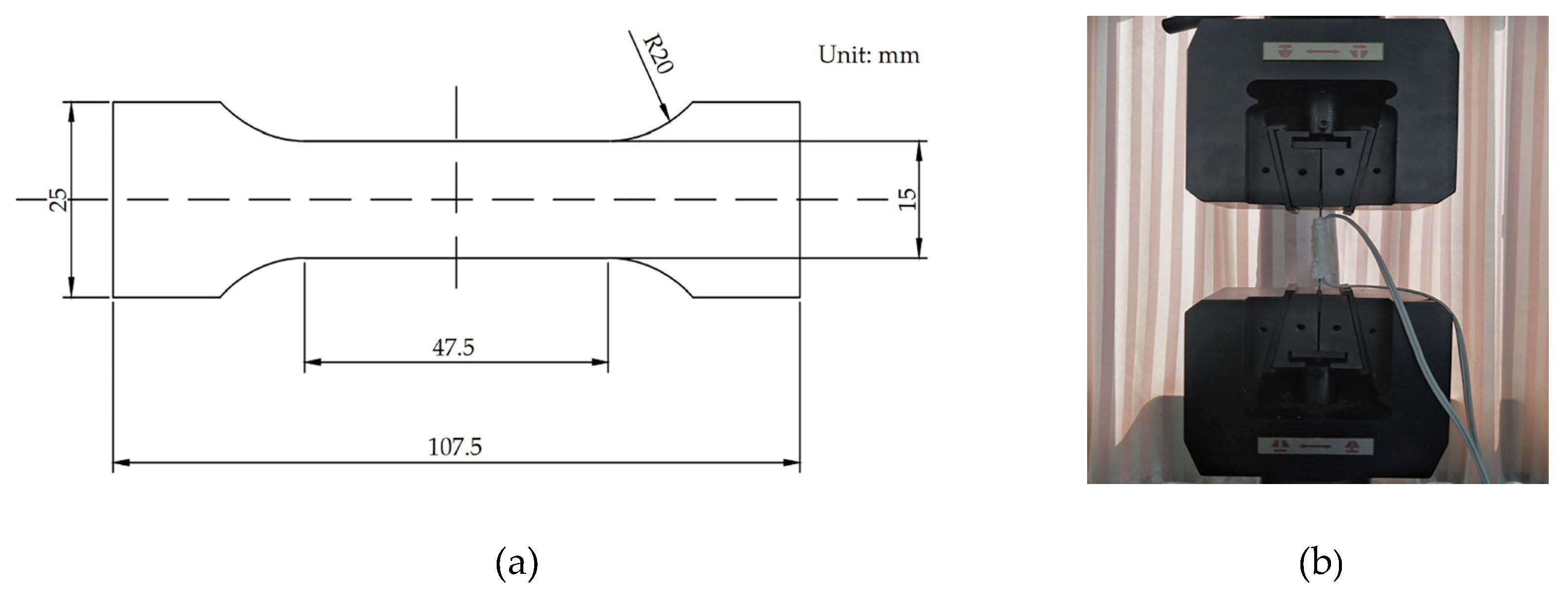
In tensile test, the CMT-4000 type universal material testing machine (Shenzhen Silver Fly Electronic Technology Co., Ltd. Shenzhen, China) was used to stretch at a tensile speed of 10 mm/min, and the strain gauge was attached to the tensile sample. The material properties of the samples were measured. Figure 2 shows the prepared tensile samples and the tensile processes.
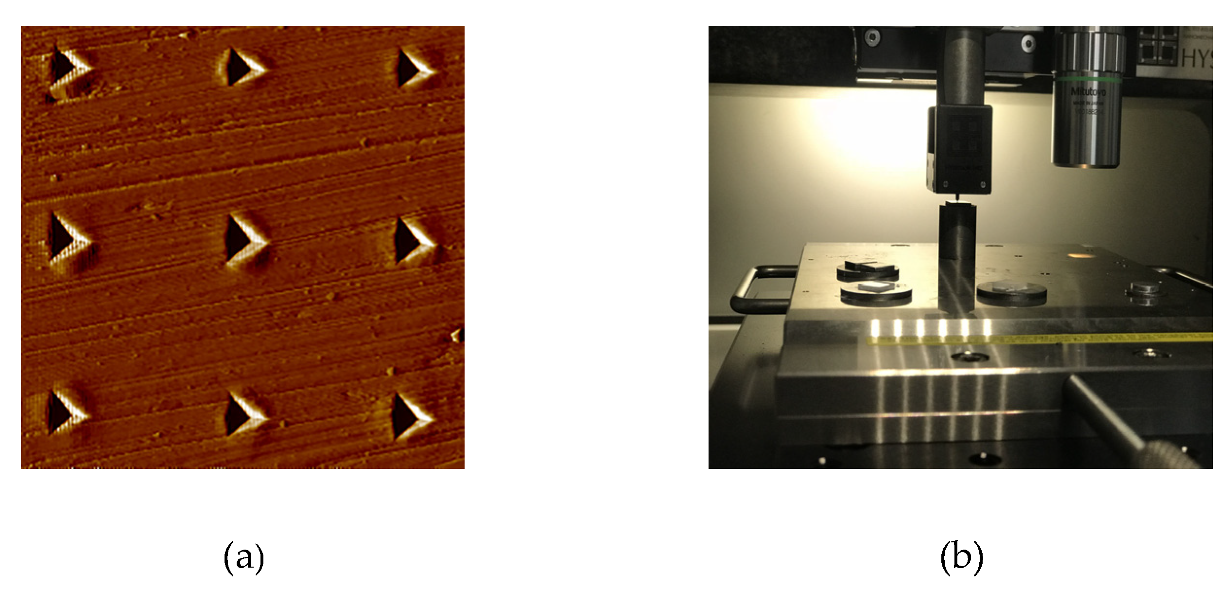
According to the measurement, the plating thickness was only 7 µm, which had very limited effect on material properties. Therefore, the nanoindentation test was conducted on the substrate. The TI-950 type nanoindenter (Hysitron Bruker Corporation, Minneapolis MN, USA) was adopted, as well as the Berkoviec indenter (Hysitron Bruker Corporation, Minneapolis MN, USA). A quasi-static method was used for testing. The load reached the maximum value 5000 mN within 15 s. After holding the pressure for 2 s, it was unloaded within 15 s at a constant rate. Figure 3 shows the protrusion and depression of the indentation and nanoindentation test processes.
2.2. Springback Compensation Theory for Bending Forming
2.2.1. Basic Assumptions
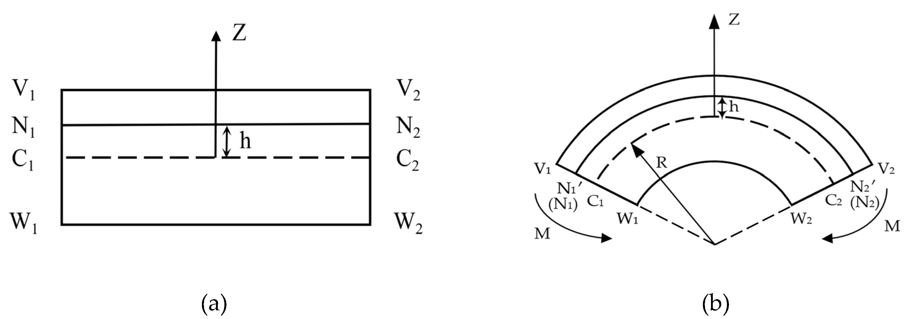
Considering that the length L from the pressing part to the free end of the sheet die is over 5 times as much as the sheet thickness t, namely L ≥ 5t, the pure bending formula can be used to calculate the transverse force bending, with the results accurate enough to meet the engineering requirements [18,19]. The sheet metal forming process can be regarded as unidirectional pure bending, as shown in Figure 5.
In the unidirectional pure bending theory, the following basic assumptions are made [20]:
(1) Plane hypothesis: cross-sections at both ends of the slab perform relative rotation under the action of bending moment, but are still perpendicular to the symmetric plane of the slab;
(2) Unidirectional stress hypothesis: suppose no extrusion between the longitudinal layers of the slats during the bending moment, there is no transverse stress, and each layer in the slab is in the state of unidirectional bending or unidirectional compression.
The Z axis shows the thickness direction of panel bending. The outer surface V1V2 of the plate is bent, while the inner surface W1W2 of the plate is compressed. After bending, the N1N2, distance h from the neutral axis C1C2 becomes N1’N2’. N is an arbitrary point in the thickness direction. The tangential engineering strain of N1N2 under the action of bending moment M can be expressed as:
where R is the radius of neutral layer curvature, k = 1/R is the neutral layer curvature after bending, and k ≥ 0, h is the distance between a certain layer and the neutral layer.
2.2.2. Springback Compensation Theory Based on Power Function Material Model
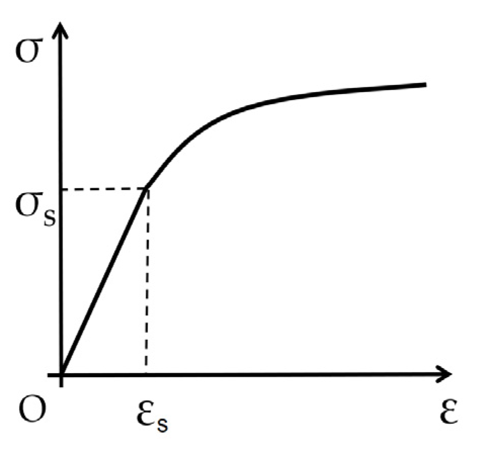
The stress-strain curve is a tool to study the bending springback problem. In order to simplify the calculation and analysis of the complicated stress-strain curve obtained by the bending experiment, the curve is usually represented approximately by a function expression.
In order to accurately describe the stress-strain relationship, the power function hardening material model is used for derivation, as shown in Figure 6.
The constitutive relations of power function materials are described as follows
where n is the hardening index obtained by nanoindentation test, and A is the strengthening coefficient, generally 1–1.15 for the research object AZM120 plates.
For a wide plate (where width b is much larger than thickness t), its unidirectional pure bending approximately meets the plane strain condition. According to the Generalized Hooke’s Law, substitute E’ for the elastic modulus E of sheet metal (, where µ is Poisson’s ratio).
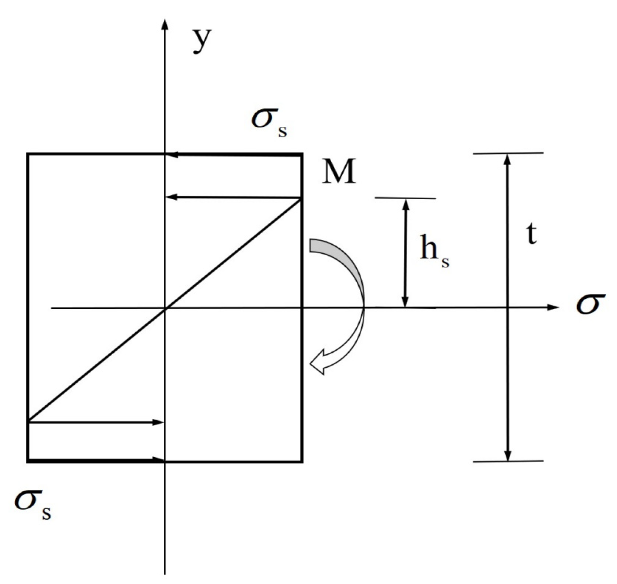
As can be observed from Figure 7, when the plate bending is in the elastic range, the formula for the ideal bending moment is
where M is the bending moment, σ is the stress, t is the plate thickness, and b is the plate width.
When the outermost layer of the plate yields, the equation for the elastic stage is σ = εE’=h·k·E, then the elastic moment Me is
where k is the curvature of plates, hs is the distance from initial yield layer to the neutral layer.
The cross-section of the bend is plastic deformation when the plate bend ships onto the stage of full plasticity deformation, and the bending moment is Mp, which refers to the plastic limit bending moment. Moreover, springback is caused by both partial plastic deformation and elastic deformation. At this time, the bending moment at the bending part is M. When imposing the bending moment M (Me ≤ M < Mp), layers that are hs away from neutral axis reach the initial yield. The integral bending moment can be given by
The relationship between the bending moment and curvature can be expressed as: . When the panel is unloaded after the bending moment M is applied, the unloading process is equivalent to the elastic effect caused by a reverse bending moment M’, and M’ = −M. Therefore, the final curvature after the springback is completed should be as follows
where the moment of inertia section I is
According to the formulas (6)–(8)
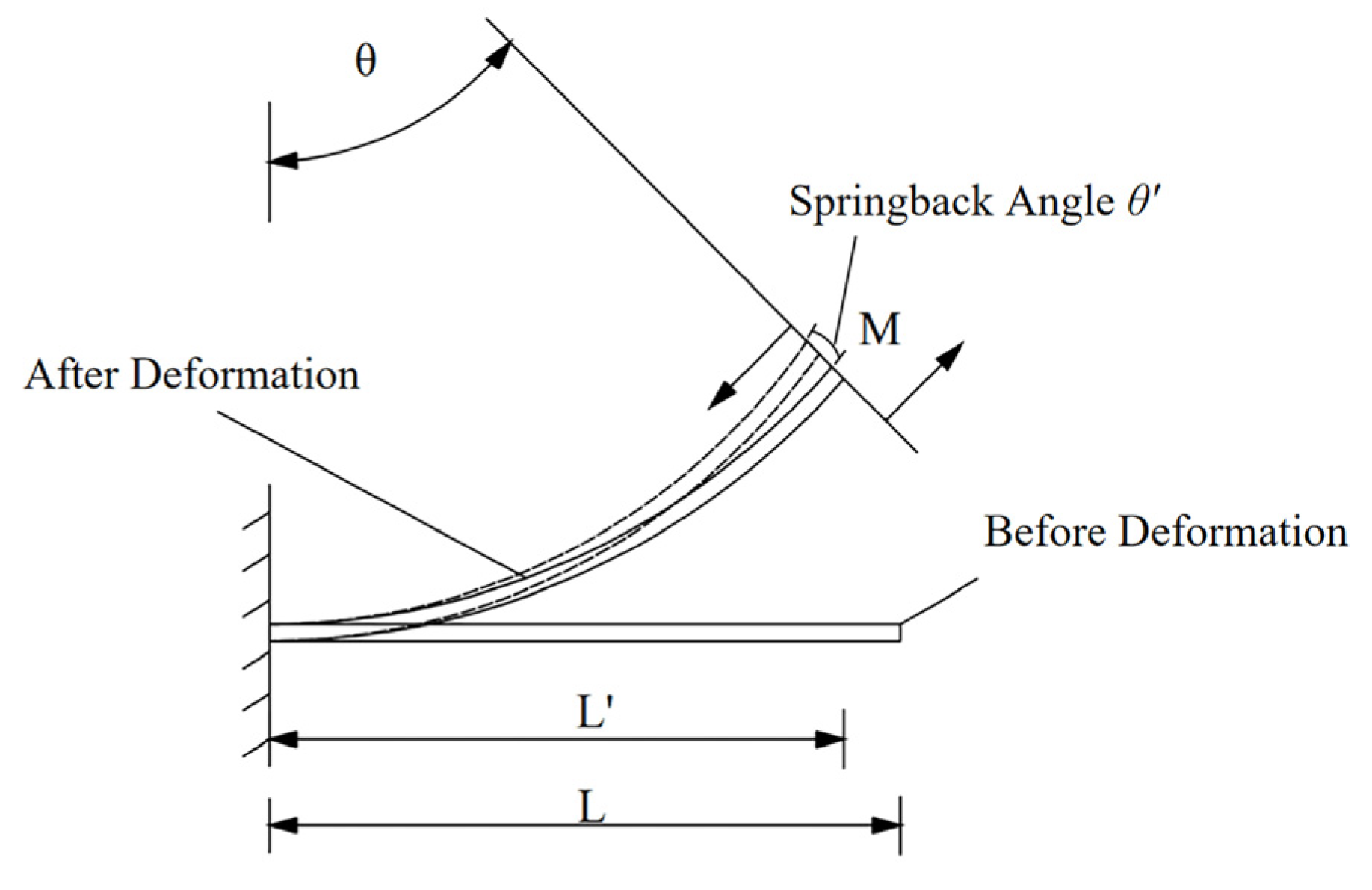
After establishing the curvature springback formula, the relationship between the curvature k and forming angle is analyzed. The schematic diagram of sheet bending is shown in Figure 8.
According to the forming method and process, the bending angle and curvature radius of sheet metal are given by
where is the target forming angle, L is the length from the bending moment to the root of plate in the initial bending state, R is the bending radius, and R = 1/K.
Substituting Equation (9) into Equation (10), the springback angle can be obtained by
where is the springback angle, and R’ = 1/K’ is the springback bending radius.
2.3. Sheet Forming Trajectory Model
This section analyzes the edge-folding trajectories of sheet and establishes the trajectory model. The model accuracy directly affects the angle of the folding trajectories and the forming quality of sheet metal, and significantly affects the control of springback.
In this section, the vector method is used for modeling. In order to ensure the efficiency and feasibility of the model, the following assumptions are made:
(1) During the forming process of the plate, the cross-section thickness of sheet metal is constant;
(2) The scratch of die tip on the surface of sheet metal is not considered in the sheet forming trajectory.
On this basis, the establishment of the plate folding track model is carried out, as shown in Figure 9.
As shown in Figure 9a, is the sum of the bend arc length and die-rolling length when the sheet is bent to the target angle, refers to the length of the straight line in the initial state of bending, and refers to the total length of the sheet bending expansion; Figure 9b is the schematic diagram established based on the model size vector formula. is the real-time angle in bending process, is the die tip radius , and is the length of arc during bending. As shown in Figure 9c,, is the target angle, is the neutral layer radius, and is the bending outer radius. The specific modeling process is as follows
where i refers to the bias coefficient of the neutral layer.
According to Figure 9a, the total length of the sheet bending expansion is
where .
where is the length of die rolling compensation in bending process, and is the length of the straight section after the panel is bent.
According to the equation , the trajectory coordinates can be expressed as
3. Results and Discussion
In this section, experiments are conducted to verify the accuracy and feasibility of the proposed springback control. Additionally, the parameters affecting the trajectory are analyzed and discussed.
3.1. Verification of Hemming Trajectory and Springback Control Effects
Typical processing conditions, i.e., an AZM120 sheet with a width of 1000 mm and a thickness of 1.5 mm, were adopted for verification. Firstly, in order to confirm the consistency between the actual and theoretical edge-folding trajectories, a laser tracker was used to collect the trajectories. The laser tracker works by installing a target ball on the test object and tracking the target ball with the light beam emitted by the tracker, so as to measure and collect the motion trajectory and position relation of the test object. The trajectory parameters selected for the test were as follows: the thickness t was 1.5 mm, the die tip radius was 2 mm, the neutral layer radius was 2.25 mm, and the bending outer radius was 3 mm. The specific testing situation is shown in Figure 10.
A comparison of the result on each trajectory is shown in Figure 11. In order to eliminate the influence of mold stiffness on the results, the no-load and full-load trajectories were collected.
In Figure 11, ‘no-load’ and ‘full-load’ show the experimental results of the actual bending trajectories of the four-side automatic panel bender with no load and full load, respectively. The experimental results of ‘no-load’ were used to prove the accuracy of the theoretical trajectory, while those of ‘full-load’ were used to estimate the impact of the actual structure deformation under load on the trajectory. It was found that the folding trajectories with no load were nearly the same as the theoretical ones (as shown in Equation (19), the mold stiffness was not considered). While there is still an 8% bias between those with full load and theoretical ones; this mainly results from the die deformation caused by the working load.
Secondly, in order to confirm the forming angle and the corresponding springback angle, the displacement sensor was used to measure the angle of in-place formation, which was compared with the theoretical springback angle, as shown in Figure 12.
The forming angle of sheet metal is the key to evaluating processing accuracy. Therefore, it is of great significance to study the relationship between different factors and the springback angle, and to verify the feasibility of the springback control proposed in this paper.
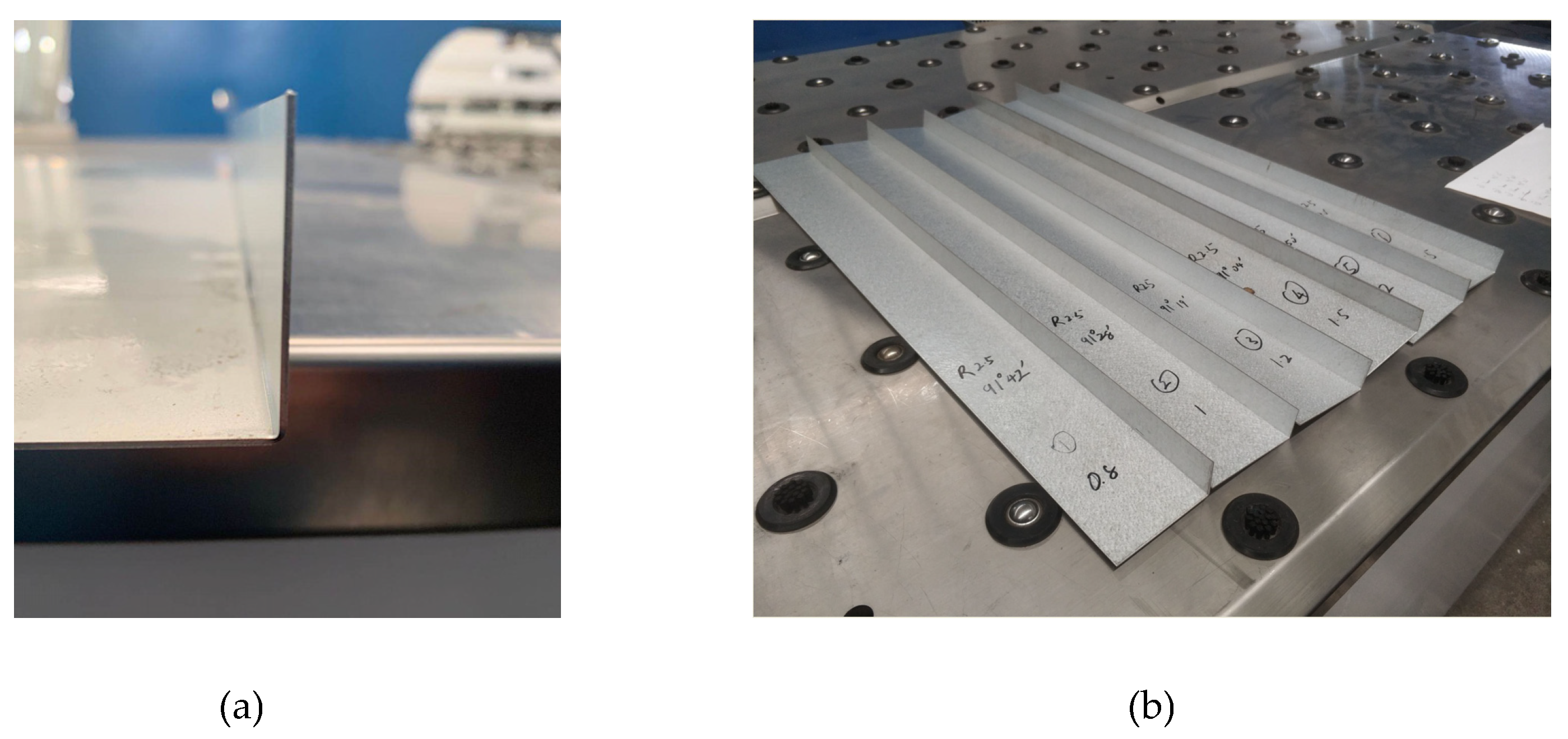
Therefore, the effects of plate thickness, forming angle, and bending radius on springback control are further studied. The bent plate examples are shown in Figure 13.
3.2. Influence Factors of Springback Control
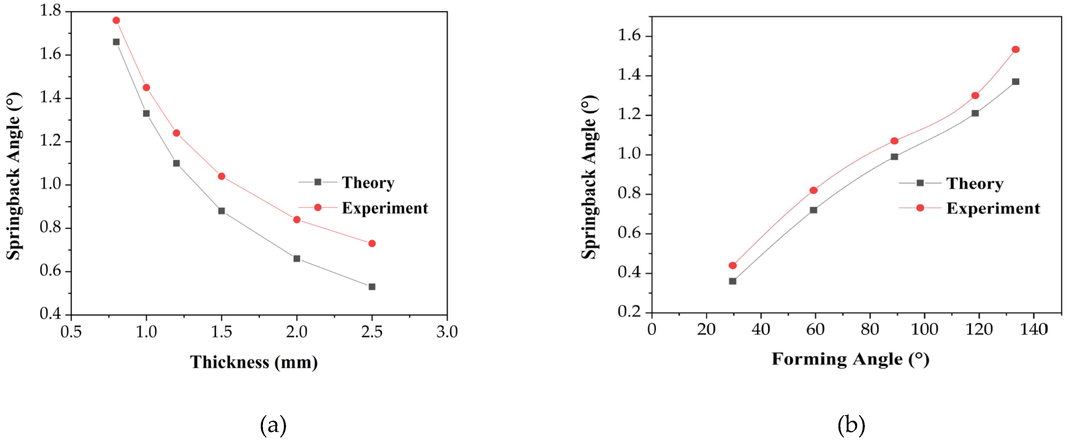
As shown in Figure 14a, AZM120 plates with different thicknesses under typical working conditions (forming angle 90°, bending radius 2.5 mm) were analyzed, comparing the theoretically calculated springback angles with actual ones in practice. Figure 14b shows the forming angles of AZM120 plates with 1.5 mm in thickness and a bending radius of 2.5 mm. In order to make the result comparison more intuitive, the thinning of plates lateral section, the offset of neutral layer, and the hardening behavior of material were not considered [21]. Experimental data are shown in Table 2.
It can be observed that the theoretical and actual springback angles decreased with the increase in plate thickness, while the gap between the two parameters widened. In addition, the difference between the theoretical and testing results at different springback angles increased gradually. This mainly resulted from the structural deformation and the difference between the pure bending model established in this study and the actual transverse force bending. This explanation is consistent with the previous trajectory verification.
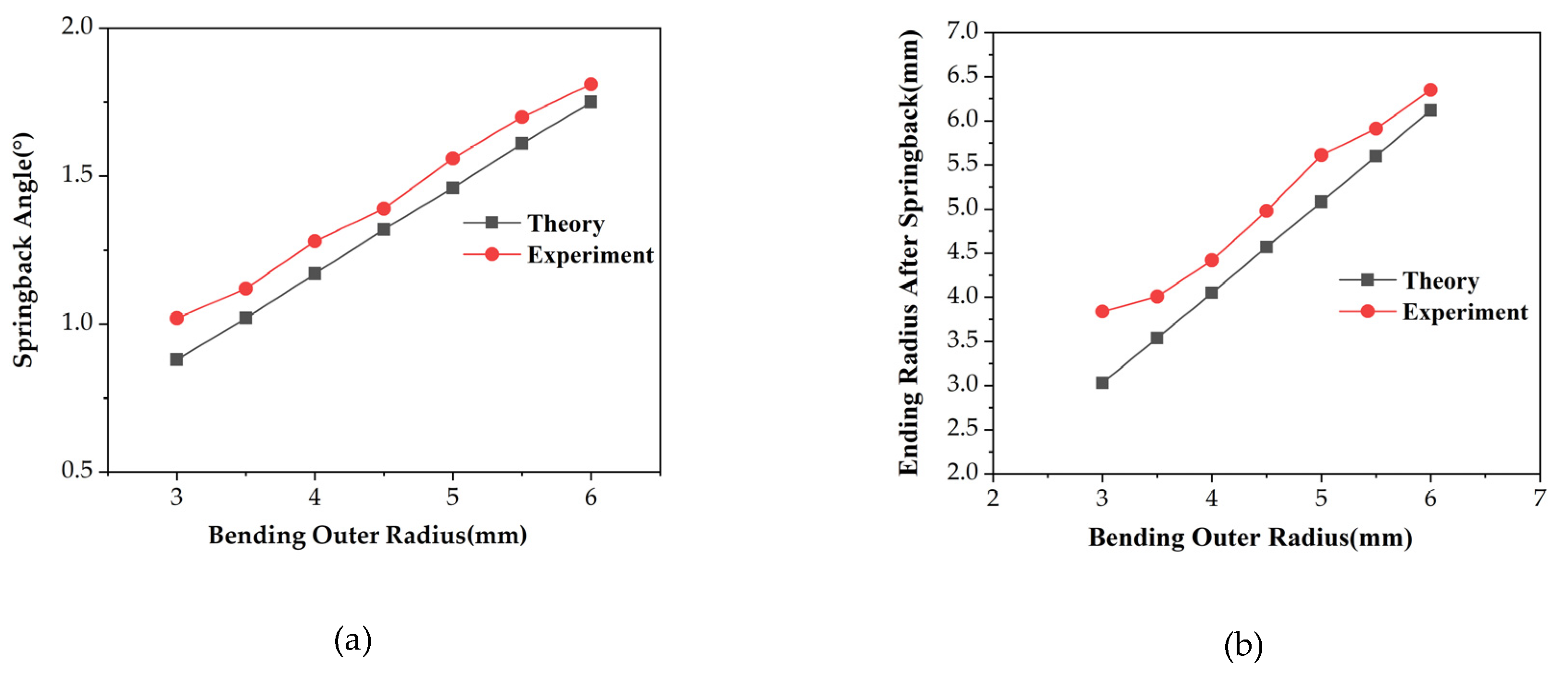
Figure 15a shows the influence of different bending radii on the springback angle. In order for comparison and analysis, the AZM120 plates of 1.5 mm thickness and bending at 90° were taken as the basic condition to compare the springback angle when the bending radii were 3, 3.5, 4, 4.5, 5, 5.5 and 6 mm. Figure 15b shows the comparison between the setpoints and actual values of the bending radius. Experimental data are shown in Table 3.
The study of the bending radius indicated that the trend of theoretical and experimental results is almost consistent. With the increase in the bending radius, springback increased, and the gap between theoretical and tested data decreased. As shown in Figure 15b, the consistency between the data of the theoretical and testing bending radius improved with the enlarging of the bending radius. The main reason for this was that the bending moment increased with the radius increases. In this case, the bending force required reduced, which facilitated the reduction of overall rigidity deformation of the automatic panel bender.
4. Conclusions
This study presented an analytical model, in which the relationship between the power function material model and the springback was taken into consideration, and the dieless forming trajectory was studied. The forming radius and the in-position angle after being rebounded can be accurately predicted by this model. Meanwhile, the influences of sheet thickness, bending radius, and forming angle in springback control were studied by comparing the theoretical calculations with the experimental tests. The following conclusions can be derived based on the obtained results:
(1) The uniaxial tension tests were carried out to obtain the true stress–strain relationship of material, which can develop the elastic-power hardening model more accurately and can be used to establish the constitutive relationship of AZM120 materials. Furthermore, the results of nanoindentation tests were carried out to replenish material performance parameters;
(2) An established springback compensation trajectory model was tested on an automatic panel bender by a laser tracker and displacement sensors. For different bending parameter combinations, the model had good generalization performance, and the precision was controlled within ±0.2°. The theory was highly consistent with testing, which provided basic data for springback compensation and prediction;
(3) The results of the experiments showed that the average absolute error between the theoretical and actual springback angle was less than 11%. Therefore, the adopted constitutive models can achieve an allowable relative error, if geometric and process parameters are appropriately selected;
(4) According to the analysis results of the various variables and the test of bending trajectory, it was found that with the thickness increases and the bending radius decreases, the bending moment increases, which causes mechnical deformation and concessions, having a significant impact on the springback angle compensation trajectory. The research on the compensation of mechanical deformation on springback is also a significant direction for the future.
Author Contributions
Conceptualization, Z.W. and J.G. (Junjie Gong); Methodology, Y.C.; Resources, J.W. and Y.W.; Writing–original draft, Z.W.; Writing–review & editing, J.G. (Junjie Gong) and J.G. (Jianhe Gao). All authors have read and agreed to the published version of the manuscript.
Funding
This research received no external funding.
Conflicts of Interest
The authors declare no conflict of interest.
References
- Liewald, M.; Hönle, S.; Sindel, M. Surface roughening of an aluminum 6016 alloy during bending and hemming. Int. J. Mater. Form. 2016, 9, 203–213. [Google Scholar] [CrossRef]
- Cui, X.; Xiao, A.; Du, Z.; Yan, Z.; Yu, H. Springback reduction of l-shaped part using magnetic pulse forming. Metals 2020, 10, 390. [Google Scholar] [CrossRef] [Green Version]
- Jia, B.; Wang, W.-W. Shape accuracy analysis of multi-point forming process for sheet metal under normal full constrained conditions. Int. J. Mater. Form. 2018, 11, 491–501. [Google Scholar] [CrossRef]
- Kim, H.-K.; Kim, W.-J. A springback prediction model for warm forming of aluminum alloy sheets using tangential stresses on a cross-section of sheet. Metals 2018, 8, 257. [Google Scholar] [CrossRef] [Green Version]
- Hill, K. Smart manufacturing drives five key changes. Manuf. Eng. 2019, 163, 14. [Google Scholar]
- Prates, P.A.; Adaixo, A.S.; Oliveira, M.C. Numerical study on the effect of mechanical properties variability in sheet metal forming processes. Int. J. Adv. Manuf. Tech. 2015, 96, 561–580. [Google Scholar] [CrossRef]
- Hill, R. The Mathematical Theory of Plasticity; Oxford university press: London, UK, 1950. [Google Scholar]
- Morestin, F.; Boivin, M.; Silva, C. Elasto plastic formulation using a kinematic hardening model for springback analysis in sheet metal forming. J. Mater. Proc. Tech. 1996, 56, 619–630. [Google Scholar] [CrossRef]
- Zhang, D.J.; Cui, Z.S.; Ruan, X.Y.; Li, Y.Q. An analytical model for predicting springback and side wall curl of sheet after U-bending. Comput. Mater. Sci. 2007, 38, 707–715. [Google Scholar] [CrossRef]
- Parsa, M.H.; al ahkami, S.N.; Pishbin, H.; Kazemi, M. Investigating spring back phenomena in double curved sheet metals forming. Mater. Des. 2012, 41, 326–337. [Google Scholar] [CrossRef]
- ul Hassan, H.; Maqbool, F.; Güner, A.; Hartmaier, A.; Khalifa, N.B.; Tekkaya, A.E. Springback prediction and reduction in deep drawing under influence of unloading modulus degradation. Int. J. Mater. Form. 2016, 9, 19–633. [Google Scholar] [CrossRef]
- Jung, J.; Jun, S.; Lee, H.-S.; Kim, B.-M.; Lee, M.-G.; Kim, J.H. Anisotropic hardening behaviour and springback of advanced high-strength steels. Metals 2017, 7, 480. [Google Scholar] [CrossRef] [Green Version]
- Zhu, H.; Chang, X.; Jung, D.W. The generation of the forming path with the springback compensation in the CNC incremental forming. Int. J. Mater. Form. 2018, 11, 455–470. [Google Scholar] [CrossRef]
- Zhang, Z.; Wu, J.; Zhang, S.; Wang, M.; Guo, R.; Guo, S. A new iterative method for springback control based on theory analysis and displacement adjustment. Int. J. Mech. Sci. 2016, 105, 330–339. [Google Scholar] [CrossRef]
- Li, Z.; Shu, X. Involute curve roller trace design and optimization in multipass conventional spinning based on the forming clearance compensation. J. Manuf. Sci. Eng. 2019, 141, 091007. [Google Scholar] [CrossRef]
- Jin, L.; Yang, Y.-F.; Li, R.-Z.; Cui, Y.W.; Jamil, M.; Li, L. Study on springback straightening after bending of the U-section of TC4 material under high-temperature conditions. Materials 2020, 13, 1895. [Google Scholar] [CrossRef] [PubMed]
- Yue, Z.; Qi, J.; Zhao, X.; Badreddine, H.; Gao, J.; Chu, X. Springback prediction of aluminum alloy sheet under changing loading paths with consideration of the influence of kinematic hardening and ductile damage. Metals 2018, 8, 950. [Google Scholar] [CrossRef] [Green Version]
- Ruderman, M.S. Fluid Dynamics and Linear Elasticity. In A First Course in Continuum Mechanics; Springer International Publishing: Cham, Switzerland, 2019. [Google Scholar] [CrossRef]
- Xue, X.; Liao, J.; Vincze, G.; Pereira, A.B.; Barlat, F. Experimental assessment of nonlinear elastic behaviour of dual-phase steels and application to springback prediction. Int. J. Mech. Sci. 2016, 117, 1–15. [Google Scholar] [CrossRef]
- Zaczynska, M.; Kolakowski, Z. The influence of the internal forces of the buckling modes on the load-carrying capacity of composite medium-length beams under bending. Materials 2020, 13, 455. [Google Scholar] [CrossRef] [PubMed] [Green Version]
- Nader, A. Springback and fracture in v-die air bending of thick stainless steel sheets. Mater. Des. 2000, 21, 217–236. [Google Scholar]
Figure 1.
Schematic illustration of folding operation.

Figure 2.
Tensile test: (a) Tensile sample size. (b) The tensile processes.

Figure 3.
Nanoindentation test: (a) Protrusion and depression of the indentation. (b) Nanoindentation test processes.
Figure 3.
Nanoindentation test: (a) Protrusion and depression of the indentation. (b) Nanoindentation test processes.

Figure 4.
Test results: (a) Load-displacement curve. (b) Stress-strain curve.

Figure 5.
Schematic diagrams before and after sheet bending: (a) Before Bending. (b) After bending.

Figure 6.
Power function material model.

Figure 7.
Stress distribution in the thickness direction.

Figure 8.
Bending of sheet metal.

Figure 9.
Schematic diagram of bending process: (a) Initial state of bending. (b) During bending. (c) After bending.
Figure 9.
Schematic diagram of bending process: (a) Initial state of bending. (b) During bending. (c) After bending.

Figure 10.
Testing situation: (a) Test on site. (b) Target ball

Figure 11.
Trajectory comparison.

Figure 12.
Sensor schematic in the springback test.

Figure 13.
Bent plate samples: (a) Sample 1. (b) Sample 2.

Figure 14.
Effects of thickness and forming angle on springback control: (a) Effect of plate thickness. (b) Effect of forming angle.
Figure 14.
Effects of thickness and forming angle on springback control: (a) Effect of plate thickness. (b) Effect of forming angle.

Figure 15.
Effect of the bending radius on springback control: (a) Effect of bending outer radius. (b) Setpoints and actual values of bending outer radius.
Figure 15.
Effect of the bending radius on springback control: (a) Effect of bending outer radius. (b) Setpoints and actual values of bending outer radius.


Table 1.
Mechanical properties of AZM120.
| Performance Parameter | 1 | 2 | 3 | Mean |
|---|---|---|---|---|
| Tensile strength Rm (MPa) | 389.6 | 393.7 | 393.3 | 392.2 |
| Poisson’s ratio (µ) | 0.310 | 0.306 | 0.336 | 0.317 |
| Elastic Modulus E (GPa) | 199.5 | 201.5 | 209.4 | 203.5 |
| Yield Strength σs (MPa) | 320.8 | 333.3 | 333.1 | 329.1 |
| Hardening index n | 0.205 | 0.216 | 0.208 | 0.21 |
Table 2.
Comparison of theoretical and test values under different forming angles and thicknesses.
| Forming Angle θ (°) | Bending outer Radius r0 (mm) | Thinkness t (mm) | Springback Angle θ’ (°) | Relative Error (%) | |
|---|---|---|---|---|---|
| Theoretical Model | Experiments | ||||
| 90 | 3 | 0.8 | 1.66 | 1.76 | 5.68% |
| 90 | 3 | 1 | 1.33 | 1.45 | 8.29% |
| 90 | 3 | 1.2 | 1.10 | 1.24 | 11.33% |
| 90 | 3 | 1.5 | 0.88 | 1.04 | 15.44% |
| 90 | 3 | 2 | 0.66 | 0.84 | 21.50% |
| 90 | 3 | 2.5 | 0.53 | 0.73 | 27.35% |
| 30 | 3 | 1.5 | 0.36 | 0.44 | 18.18% |
| 60 | 3 | 1.5 | 0.72 | 0.82 | 12.20% |
| 90 | 3 | 1.5 | 0.88 | 1.02 | 14.08% |
| 120 | 3 | 1.5 | 1.21 | 1.30 | 6.92% |
| 135 | 3 | 1.5 | 1.37 | 1.53 | 10.65% |
Table 3.
Comparison of theoretical and test values under different bending radius.
| Forming Angle θ (°) | Bending outer Radius t0 (mm) | Thinkness t (mm) | Springback Angle θ’ (°) | Relative Error (%) | ||
|---|---|---|---|---|---|---|
| Target | Test | Theoretical Model | Experiments | |||
| 90 | 3.0 | 3.84 | 1.5 | 0.88 | 1.02 | 14.08% |
| 90 | 3.5 | 4.01 | 1.5 | 1.02 | 1.12 | 8.69% |
| 90 | 4.0 | 4.42 | 1.5 | 1.17 | 1.28 | 8.67% |
| 90 | 4.5 | 4.98 | 1.5 | 1.32 | 1.39 | 5.37% |
| 90 | 5.0 | 5.61 | 1.5 | 1.46 | 1.56 | 6.29% |
| 90 | 5.5 | 5.91 | 1.5 | 1.61 | 1.7 | 5.39% |
| 90 | 6.0 | 6.35 | 1.5 | 1.75 | 1.81 | 3.05% |
© 2020 by the authors. Licensee MDPI, Basel, Switzerland. This article is an open access article distributed under the terms and conditions of the Creative Commons Attribution (CC BY) license (http://creativecommons.org/licenses/by/4.0/).
Share and Cite
MDPI and ACS Style
Wu, Z.; Gong, J.; Chen, Y.; Wang, J.; Wei, Y.; Gao, J. Springback Prediction of Dieless Forming of AZM120 Sheet Metal Based on Constitutive Model. Metals 2020, 10, 780. https://doi.org/10.3390/met10060780
AMA Style
Wu Z, Gong J, Chen Y, Wang J, Wei Y, Gao J. Springback Prediction of Dieless Forming of AZM120 Sheet Metal Based on Constitutive Model. Metals. 2020; 10(6):780. https://doi.org/10.3390/met10060780
Chicago/Turabian StyleWu, Zijin, Junjie Gong, Yangdong Chen, Jinrong Wang, Yuanyuan Wei, and Jianhe Gao. 2020. "Springback Prediction of Dieless Forming of AZM120 Sheet Metal Based on Constitutive Model" Metals 10, no. 6: 780. https://doi.org/10.3390/met10060780
Note that from the first issue of 2016, this journal uses article numbers instead of page numbers. See further details here.