1. Introduction
Over the last few years, there has been a growing interest in the development of ultrafine-grained materials (UFG) as a consequence of the improvement in their mechanical properties, compared to those obtained in a non-nanostructured state [
1]. These properties make these materials attractive for potential industrial applications [
2]. One of the main ways to obtain bulk ultrafine-grained materials is by means of severe plastic deformation (SPD) processes, where equal channel angular pressing (ECAP) is one of the main processes used to obtain these materials. This process has several innovative technological characteristics compared to traditional metal-working processes [
3]. It consists of the extrusion of a material by employing a die that has two channels that intersect at an angle usually comprised between 90° and 120° [
4]. Moreover, it is possible to obtain bulk ultrafine-grained materials with SPD processes that do not use an angular channel such as high-pressure torsion (HPT) [
5], repetitive corrugation and straightening (RCS) [
6], and high-pressure torsion extrusion (HPTE) [
7].
One of the main advantages of SPD processes is the possibility to obtain bulk materials that can be used to develop mechanical components with improved properties. In this way, Kim et al. developed micro-gears from ECAP’ed AA6061 at 443 and 553 K by using the forward extrusion [
8]. These authors found that this forward extrusion process could be carried out without a significant loss of the mechanical properties which had been previously developed by ECAP [
8]. In a study by Luis Pérez et al. [
9], two gears, with different modules, made of AA5083 after ECAP were obtained; an improvement in the microhardness of approximately 13.6% was observed with respect to that obtained in the gears developed by forging of the annealed AA5083, and, in a study by Lee et al. [
10], a magnesium alloy impeller with twisted blades and an ultrafine grain size was analysed. Some other research works have studied the effect of ECAP on the wear properties of parts manufactured in this way. However, the number of these studies was far lower than those research studies that dealt with the mechanical and microstructural properties of these materials. Among these studies, that by Ortiz et al. [
11] analysed the effect of the severe plastic deformation on the tribological properties of the so-processed materials by ball-on-disk tests. These authors analysed the sliding wear resistance in an Al–Mg–Si alloy that was previously-processed by ECAP. They found that the wear resistance increased as the number of ECAP passages was also increased. The research work by Thiyaneshwaran and Sureshkumar [
12] studied the wear behaviour of the AA5083 before and after being processed twice by ECAP with the Bc route at room temperature. This study analysed the influence of ECAP on the microstructure, mechanical properties, and wear resistance of the chosen alloy. The authors found that the wear resistance increased due to the refinement of the grain size obtained by ECAP [
12]. In a study by Chegini et al. [
13], AA7075 was processed by ECAP using route Bc. In order to study wear behaviour, these authors carried out tests with a piece of pin-on-disk equipment using different loads and sliding velocities. The authors carried out a study of the effect of ECAP processing on wear by using scanning electron microscopy (SEM) and transmission electron microscopy. They concluded that wear resistance was increased in the ultrafine-grained material. Likewise, they indicated that the main wear mechanism could be attributed to adhesive wear and delamination [
13].
Some other studies have analysed the effect of ECAP processing on wear in materials others than aluminium alloys. For example, in the research work by Li et al. [
14], the wear resistance of a copper zirconium alloy processed by ECAP was studied. To this end, ball-on-disc tests were carried out on specimens with both annealed and ECAP’ed materials. They found that ECAP processing led to a decrease in wear depth and wear volume loss [
14]. In a study by Luri et al. [
15], the wear behaviour of connecting-rods obtained from material that was previously-processed by ECAP was analysed. This behaviour was compared to that obtained from material forged from an annealed state. A better wear resistance was obtained in the materials that were previously-processed by ECAP than that obtained in not previously ECAP’ed materials [
15]. On the other hand, Avcu [
16] analysed the dry sliding behaviour of an ECAP-processed AA7075 aluminium alloy and found that the coefficient of friction, the volume loss, the mass loss and the specific wear rate were increased with ECAP. In regard to finite elements simulations, most of results found in the literature to model wear behaviour have been developed for specific tribological systems (two materials in particular, a specific contact geometry and for a specific environment and lubricant). Moreover, operational conditions have usually also been stated. Among many other studies, in the research work by Wang et al. [
17], the mechanism of erosion in ductile and fragile metals was studied. In the work of Spiegelberg and Andersson [
18], wear simulations were based on a generalized form of the Archard wear model, and in the research study by Shirzadegan et al. [
19], a numerical model was developed in order to simulate contacts with elastohydrodynamic lubrication in cam mechanisms.
Several studies have dealt with improvements in the mechanical properties of materials obtained by using SPD. However, the number of research studies that have dealt with the development of mechanical components, as well as the number of studies that have analysed the in-service behaviour of such developed parts, is significantly lower. Therefore, this present research study aimed to fill this gap, and it presents some results obtained from an experimental analysis of the wear undergone by a mechanical components of the cam type; these components were tested by using equipment with a block-on-ring configuration that was specifically developed for testing the in-service wear behaviour of such mechanical parts. The wear tests for the functioning of the cams were designed as accelerated wear tests where these cams are intended to be used to give movement to the valves of traditional combustion engines.
Though there have been some studies where wear tests have been carried out on samples extracted from the original ECAP’ed billets of aluminium alloys, in this present research study, the wear tests were performed on functional parts—in this case, a cam that had been manufactured from an ECAP’ed aluminium alloy (AA5083) by a forging process. It is considered that this difference between the present study and other previous ones is really important, and it is this aspect of performing the wear tests on functional and real mechanical components and not on laboratory samples that makes it novel. The aluminium alloy that was employed (AA5083) was isothermally-forged to obtain the cams from both annealed material and previously ECAP-processed material. In addition, FEM simulations were included in order to model material wear. A comparative analysis between both FEM and experimental results is also included in this present study.
2. Set-Up of the Experiment
An aluminium–magnesium alloy (AA-5083) was studied in this research work. First, it was subjected to a heat treatment of annealing that consisted of a heating slope over 1 h up to a temperature of 345 °C that was maintained over 2 h, followed by a final slow cooling down to room temperature inside the furnace. This aluminium alloy was then isothermally-forged to obtain mechanical components of the cam type. The wear behaviour that the cams undergo when manufactured in this manner was analysed. Two initial states were considered: an annealed material and an ECAP-processed material that had been previously subjected to the annealing process. The grain size of the ECAP-processed material fell within the submicrometric range. This refinement in the grain size has been widely studied and is due to the introduction of high strain values in the material. At the same time, mechanical properties such as hardness, yield strength, tensile strength, and fatigue strength are improved. Moreover, depending on the process conditions, forgeability may also be improved.
This ECAP processing was carried out by using an extrusion press at the Public University of Navarre (Spain). The ECAP die had a circular cross-section with a diameter of 20 mm, and it had a configuration of equal fillet radii with a value of 5 mm. The angle between the entrance channel and the exit channel was 90°. Two ECAP passages were carried out at room temperature by using route C, where this route consists in rotating the material billet 180° after each passage. Then, these parts were isothermally-forged to manufacture the cams. This isothermal forging process was also carried out on this aluminium alloy but with an annealed microstructure as the starting material in order to compare the results obtained. The microstructure and the mechanical properties of this aluminium alloy before and after ECAP processing can be found in a research study by León et al. [
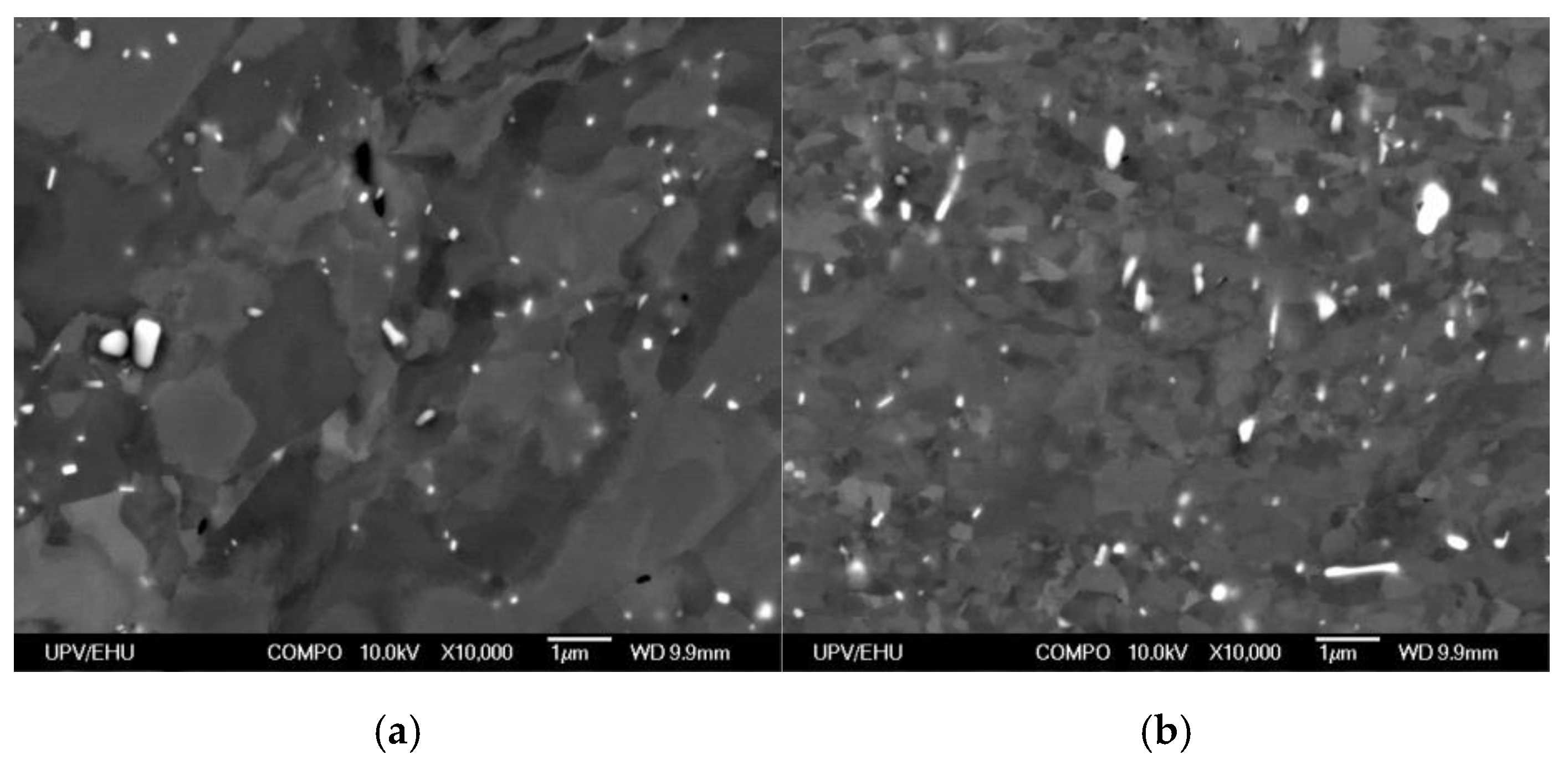
20] (see
Figure 1), where a new flow stress that is valid for both a wide temperature range and different initial deformation conditions in the starting material was also proposed.
As can be observed in
Figure 1, the effects of ECAP on isothermal forging were beneficial in terms of microstructure and mechanical properties. The forging of the ECAP-processed AA5083 produced a finer and more homogeneous microstructure in the manufactured cam in relation to the forging of the annealed AA5083. In the case of the cam under consideration in this study, an increase from 107.5 to 118.6 HV (that is, of 10.3%) was obtained in the microhardness mean value. In addition, the annealed AA5083 had a mean grain size of 200 µm, and the ECAP-processed material from the forged cam had a grain size as fine as 250 nm [
21].
After being processed by ECAP, the aluminium alloy was isothermally-forged. The forging temperature employed was 200 °C. In this present study, these parts are referred as AA-5083-N2-T200. In order to be able to compare the results obtained with those obtained by using a conventional process, cams of the same aluminium alloy were isothermally-forged from annealed materials at the same temperatures as the ones used for the cams previously-processed by ECAP. These parts are referred in this study as AA-5083-N0-T200. Once these mechanical components were manufactured, a final machining process was carried out on the cams in order to obtain the final shape (see
Figure 2 for an outline of the overall manufacturing process of the cams). The dies to obtain the cams and the design process of the cams can be found in a study by Salcedo et al. [
21], where the development of ultrafine-grained cams obtained from previously a ECAP-processed material and manufactured by isothermal forging was shown. A comparison between the mechanical properties obtained in the cams manufactured from a material with no previous deformation and with those manufactured from a previously SPD-processed material was also included. However, a study by Salcedo et al. [
21] did not deal with the wear behaviour of these mechanical components. Hence, this present research study continued the earlier research works on the analysis of mechanical and microstructure properties of these mechanical components obtained from SPD processes, and, in this present study, the in-service wear behaviour of isothermally-forged cams is shown.
The main aim of this present study was to determine how an SPD process affects the in-service behaviour of cams with regard to wear. As can be observed in
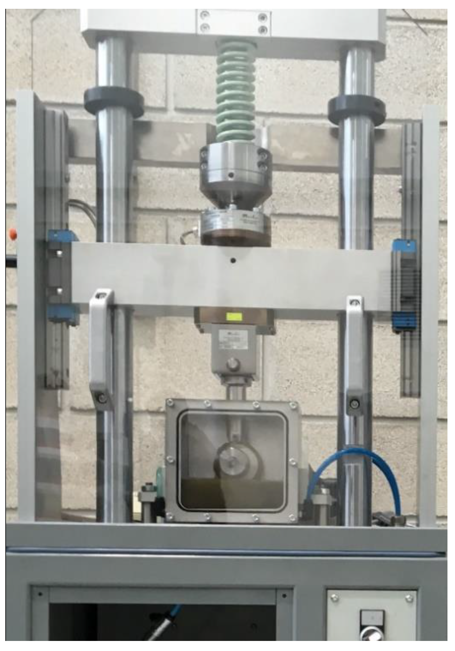
Figure 2, severe plastic-deformed materials and annealed materials were employed in order to manufacture the cams. These thusly manufactured mechanical components were tested in working conditions by using a piece of equipment specifically designed for such a purpose. This equipment, which is installed at the Public University of Navarre, is shown in
Figure 3. As can be observed, it may be considered to have a block-on-ring configuration. The equipment to carry out the experimental test in order to determine the wear behaviour of the cams consisted of a cam-follower system. An electric motor drive made the cam rotate and so the cam pushed a follower upwards that moved vertically and compressed a spring, which was pre-loaded in order to apply a specific force. To this end, the cam to be tested was placed in the bottom dead centre. Furthermore, it was possible to introduce a preload (
F0) so that the cams could be tested under the desired working conditions.
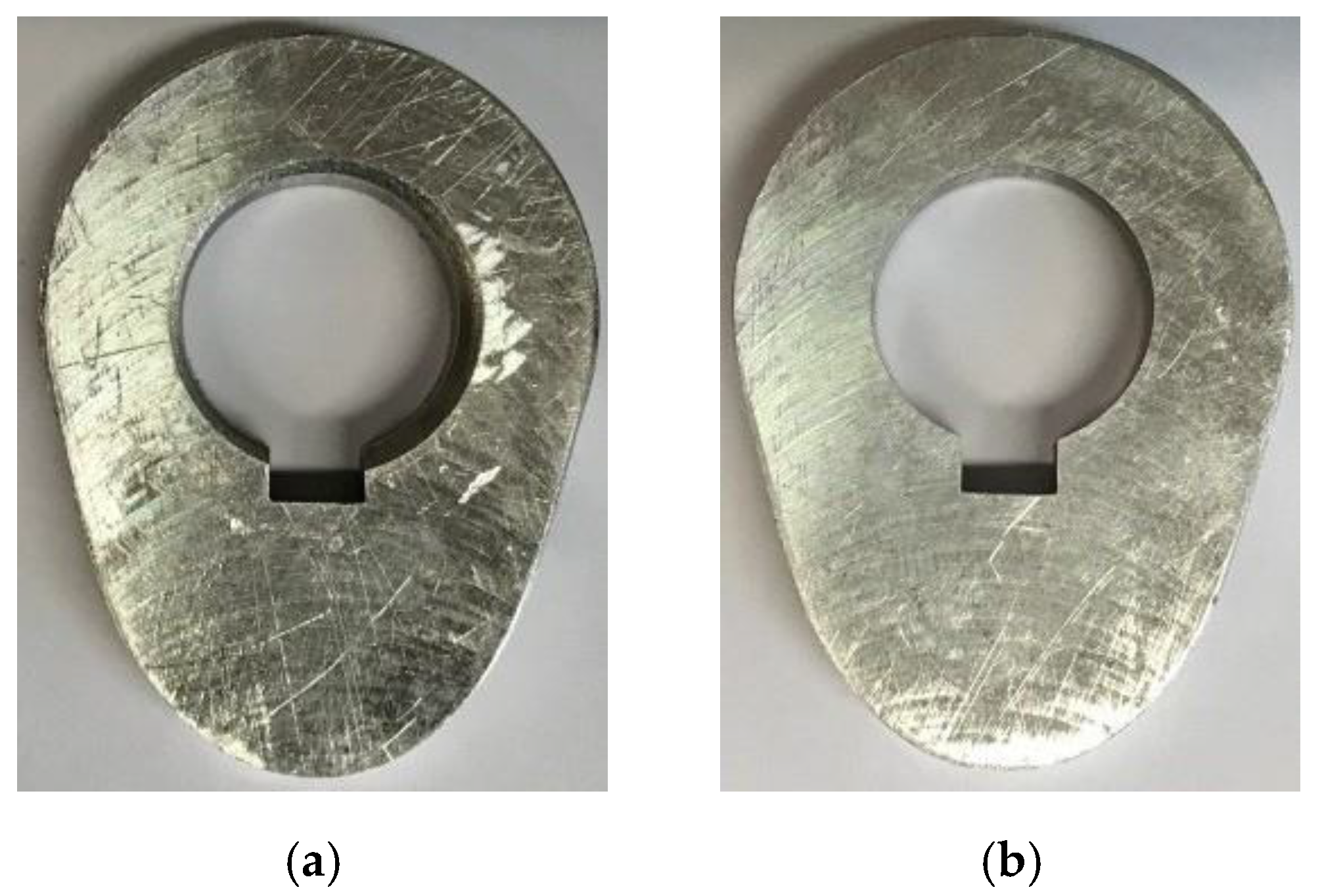
As was previously mentioned, a heat treatment of annealing at 345 °C was first applied to a 5083 aluminium alloy. Then, the cams were manufactured. For the second initial state, the same heat treatment was carried out. Subsequently, it was processed twice by SPD using ECAP and route C at room temperature. The processing velocity was 50 mm/min. The material was isothermally-forged to obtain the cams at a temperature of 200 °C. Finally, all the cams were machined to obtain the final shape. These cams are shown in
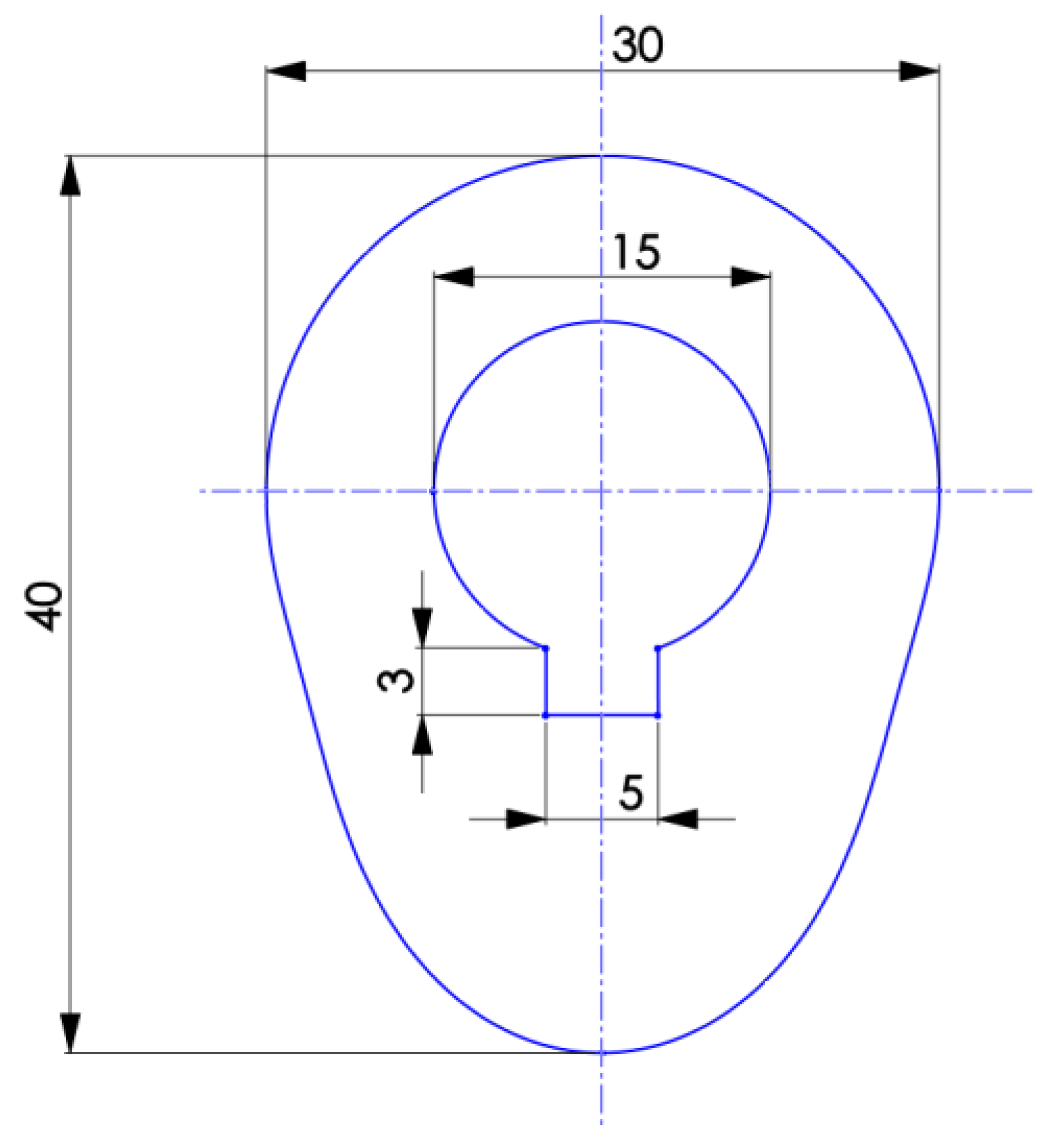
Figure 4. In addition, the dimensions and the geometry of the final profile of the radial cam are shown in
Figure 5. It was a cam with a stop at 180° and a distance between top and bottom dead centres of 10 mm.
The cams were placed on the equipment shown in
Figure 3, and they were tested under a preload of 100 N, with a spring with a stiffness constant of 10.2 N/mm and at a rotational speed of 60 rpm. The cams were tested up to 200 × 10
3 revolutions. The cams were weighed on a precision weighing scale before and after the wear tests at 50 × 10
3, 100 × 10
3, and 200 × 10
3 rev in order to determine the volume loss with the functioning time for each of the cams. The precision weighing scale used (Mettler Toledo XS104; Mettler-Toledo, Columbus, OH, USA) has an uncertainty value of (0.04 + 2 × 10
−7 × weight) mg. Three different weight measurements were carried out for each sample at each number of cycles under consideration with the mean values shown in
Table 1. An SAE 5W30 oil (Shell, The Hague, The Netherlands) was used as a lubricant for all the cams tested, using new oil for each test so that all wear tests were carried out under the same conditions. The friction couple was composed of AA5083 and hardened steel.
Once the cams were tested following the earlier-mentioned procedure, they were cut in order to be analysed via SEM. Prior to observation, they were cleaned with acetone to remove any remaining spots of lubricant. A JEOL 6400 scanning electron microscope (JEOL, Tokyo, Japan) was used, and the operating parameters were an acceleration voltage of 20 kV and a beam current of around 0.1 nA. Secondary electrons were used to obtain the micrographs from the cut samples.
Author Contributions
All the authors of this present manuscript have approximately equally contributed to most of the research tasks. However, C.J.L.P., R.L.I., J.P.F.B., J.L.I., D.S.P., and I.P.A. contributed to a great extent in performing the experiments (investigation); C.J.L.P. and R.L.I. contributed to a great extent in conceiving and designing the experiments as well as in analysing the data (formal analysis), and R.L.I., C.J.L.P., and D.S.P. made the FEM simulations (software). All authors have read and agreed to the published version of the manuscript.
Funding
This research was funded by the Spanish Ministry of Science and Innovation (former Spanish Ministry of Economy and Competitiveness) through the Research Project DPI2013-41954-P.
Acknowledgments
The authors of this present research work acknowledge the support given by the Spanish Ministry of Science and Innovation (former Spanish Ministry of Economy and Competitiveness) through the Research Project DPI2013-41954-P. The authors also thank for technical and human support provided by SGIker (UPV/EHU/ERDF, EU).
Conflicts of Interest
The authors declare no conflict of interest.
References
- Valiev, R.Z.; Islamgaliev, R.K.; Alexandrov, I.V. Bulk nanostructured materials from severe plastic deformation. Prog. Mater. Sci. 2000, 45, 103–189. [Google Scholar] [CrossRef]
- Zhu, Y.T.; Lowe, T.C.; Langdon, T.G. Performance and applications of nanostructured materials produced by severe plastic deformation. Scr. Mater. 2004, 51, 825–830. [Google Scholar] [CrossRef]
- Segal, V.M. Materials processing by simple shear. Mater. Sci. Eng. A 1995, 197, 157–164. [Google Scholar] [CrossRef]
- Valiev, R.Z.; Langdon, T.G. Principles of equal-channel angular pressing as a processing tool for grain refinement. Prog. Mater. Sci. 2006, 51, 881–981. [Google Scholar] [CrossRef]
- Vorhauer, A.; Pippan, R. On the homogeneity of deformation by high pressure torsion. Scr. Mater. 2004, 51, 921–925. [Google Scholar] [CrossRef]
- Huang, J.; Zhu, Y.T.; Alexander, D.J.; Liao, X.; Lowe, T.C.; Asaro, R.J. Development of repetitive corrugation and straightening. Mater. Sci. Eng. A 2004, 371, 35–39. [Google Scholar] [CrossRef]
- Ivanisenko, Y.; Kulagin, R.; Fedorov, V.; Mazilkin, A.; Scherer, T.; Baretzky, B.; Hahn, H. High Pressure Torsion Extrusion as a new severe plastic deformation process. Mater. Sci. Eng. A 2016, 664, 247–256. [Google Scholar] [CrossRef]
- Kim, W.J.; Sa, Y.K.; Kim, H.K.; Yoon, U.S. Plastic forming of the equal-channel angular pressing processed 6061 aluminum alloy. Mater. Sci. Eng. A 2008, 487, 360–368. [Google Scholar] [CrossRef]
- Luis Pérez, C.J.; Salcedo Pérez, D.; Puertas Arbizu, I. Design and mechanical property analysis of ultrafine grained gears from AA5083 previously processed by equal channel angular pressing and isothermal forging. Mater. Des. 2014, 63, 126–135. [Google Scholar] [CrossRef]
- Lee, J.H.; Kang, S.H.; Yang, D.Y. Novel forging technology of a magnesium alloy impeller with twisted blades of micro-thickness. CIRP Ann. 2008, 57, 261–264. [Google Scholar] [CrossRef]
- Ortiz-Cuellar, E.; Hernandez-Rodriguez, M.A.L.; García-Sanchez, E. Evaluation of the tribological properties of an Al-Mg-Si alloy processed by severe plastic deformation. Wear 2011, 271, 1828–1832. [Google Scholar] [CrossRef]
- Thiyaneshwaran, N.; Sureshkumar, P. Microstructure, mechanical and wear properties of aluminum 5083 alloy processed by equal channel angular extrusion. Int. J. Eng. Res. Technol. 2013, 2, 17–24. [Google Scholar]
- Chegini, M.; Fallahi, A.; Shaeri, M.H. Effect of Equal Channel Angular Pressing (ECAP) on wear behavior of Al-7075 alloy. Procedia Mater. Sci. 2015, 11, 95–100. [Google Scholar] [CrossRef] [Green Version]
- Li, J.; Wongsa-Ngam, J.; Xu, J.; Shan, D.; Guo, B.; Langdon, T.G. Wear resistance of an ultrafine-grained Cu-Zr alloy processed by equal-channel angular pressing. Wear 2015, 326, 10–19. [Google Scholar] [CrossRef]
- Luri, R.; Luis, C.J.; León, J.; Fuertes, J.P.; Salcedo, D.; Puertas, I. Analysis of Fatigue and Wear Behaviour in Ultrafine Grained Connecting Rods. Metals 2017, 7, 289. [Google Scholar] [CrossRef] [Green Version]
- Avcu, E. The influences of ECAP on the dry sliding wear behaviour of AA7075 aluminium alloy. Tribol. Int. 2017, 110, 173–184. [Google Scholar] [CrossRef]
- Wang, Y.F.; Yang, Z.G. Finite element model of erosive wear on ductile and brittle materials. Wear 2008, 265, 871–878. [Google Scholar] [CrossRef]
- Spiegelberg, C.; Andersson, S. Simulation of friction and wear in the contact between the valve bridge and rocker arm pad in a cam mechanism. Wear 2006, 261, 58–67. [Google Scholar] [CrossRef]
- Shirzadegan, M.; Almqvist, A.; Larsson, R. Fully coupled EHL model for simulation of finite length line cam-roller follower contacts. Tribol. Int. 2016, 103, 584–598. [Google Scholar] [CrossRef] [Green Version]
- León, J.; Luis, C.J.; Juan, P.; Fuertes, I.P.; Rodrigo, L.; Daniel, S. A Proposal of a Constitutive Description for Aluminium Alloys in both Cold and Hot Working. Metals 2016, 6, 244. [Google Scholar] [CrossRef] [Green Version]
- Salcedo, D.; Luis, C.J.; Luri, R.; Puertas, I.; León, J.; Fuertes, J.P. Design and Mechanical Properties Analysis of AA5083 Ultrafine Grained Cams. Metals 2017, 7, 116. [Google Scholar] [CrossRef] [Green Version]
- Evaluation of Measurement Data—Guide to the Expression of Uncertainty in Measurement (GUM); BIPM: Sèvres, France, 1995.
- Marc® Mentat® 2018; MSC Software Corporation: Hamburg, Germany, 2018.
- Simufact Forming 15.0; MSC Software Corporation: Hamburg, Germany, 2018.
Figure 1.
SEM micrographs of different isothermally-forged AA5083 states: (
a) AA5083 at N0 (annealed); (
b) AA5083 at N2 (ECAP-processed). Taken from the research work by León et al. [
20].
Figure 2.
Manufacturing process to obtain the cams with and without previous ECAP processing, where in both study cases, AA5083 was firstly subjected to a heat treatment of annealing.
Figure 3.
Equipment for testing the in-service wear behaviour of mechanical parts.
Figure 4.
Cams after the wear tests (200 × 103 rev): (a) AA5083-N0-T200; (b) AA5083-N2-T200.
Figure 5.
Geometry and final dimensions of the radial cam employed in the wear tests, where the dimensions are expressed in mm.
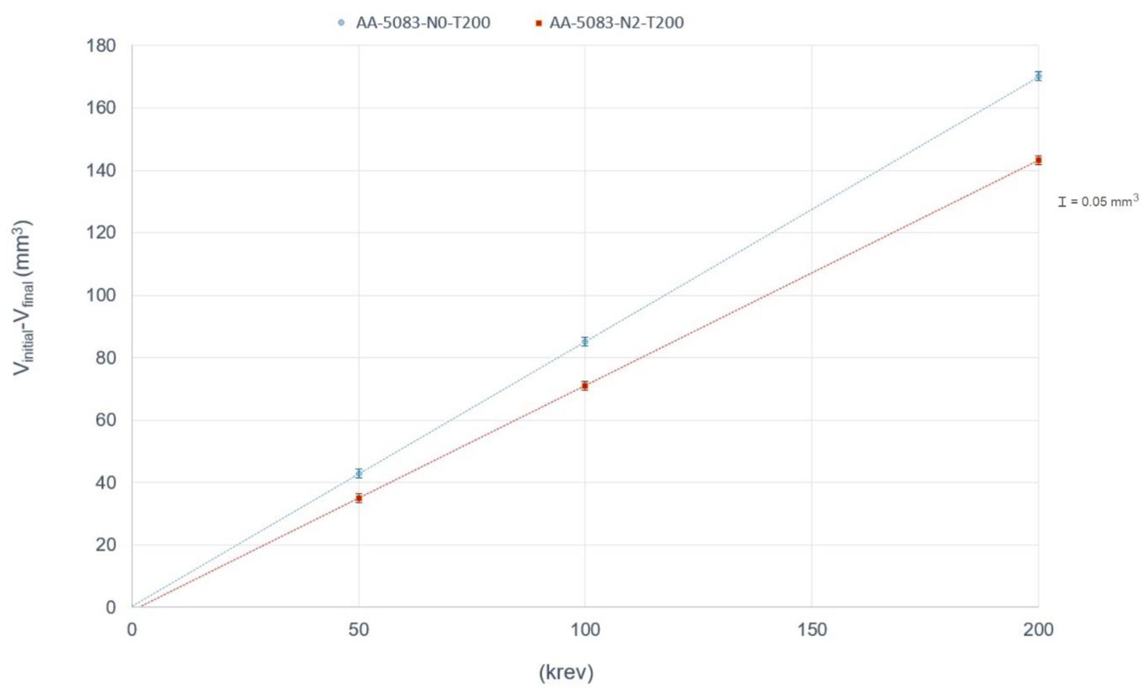
Figure 6.
Wear versus revolutions for the isothermally-forged cams, where the scale for the uncertainty values has been amplified as indicated in order to be plotted more clearly.
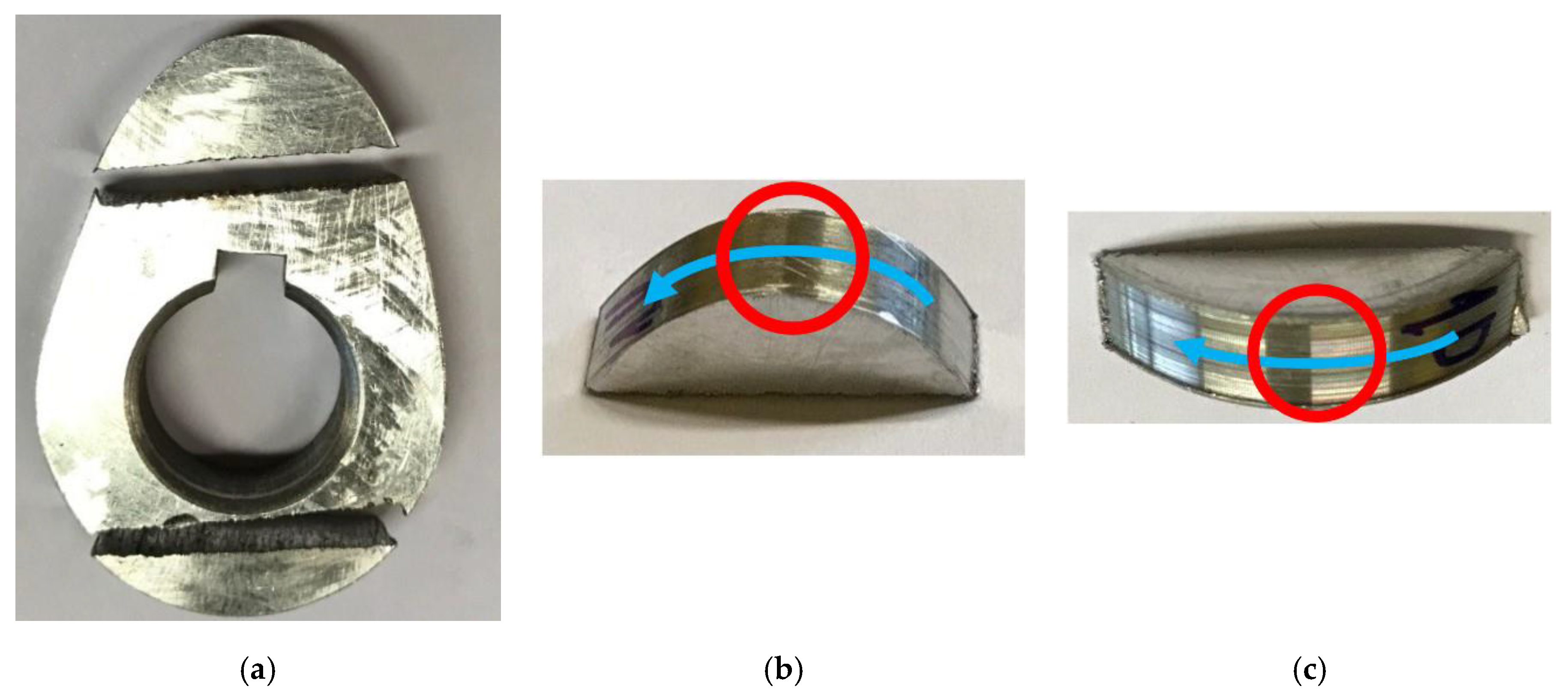
Figure 7.
Study zones of the worn cam (highlighted with red circles), where the blue arrows show the direction of the grooves: (a) cam cut into three parts; (b) upper zone; (c) lower zone.
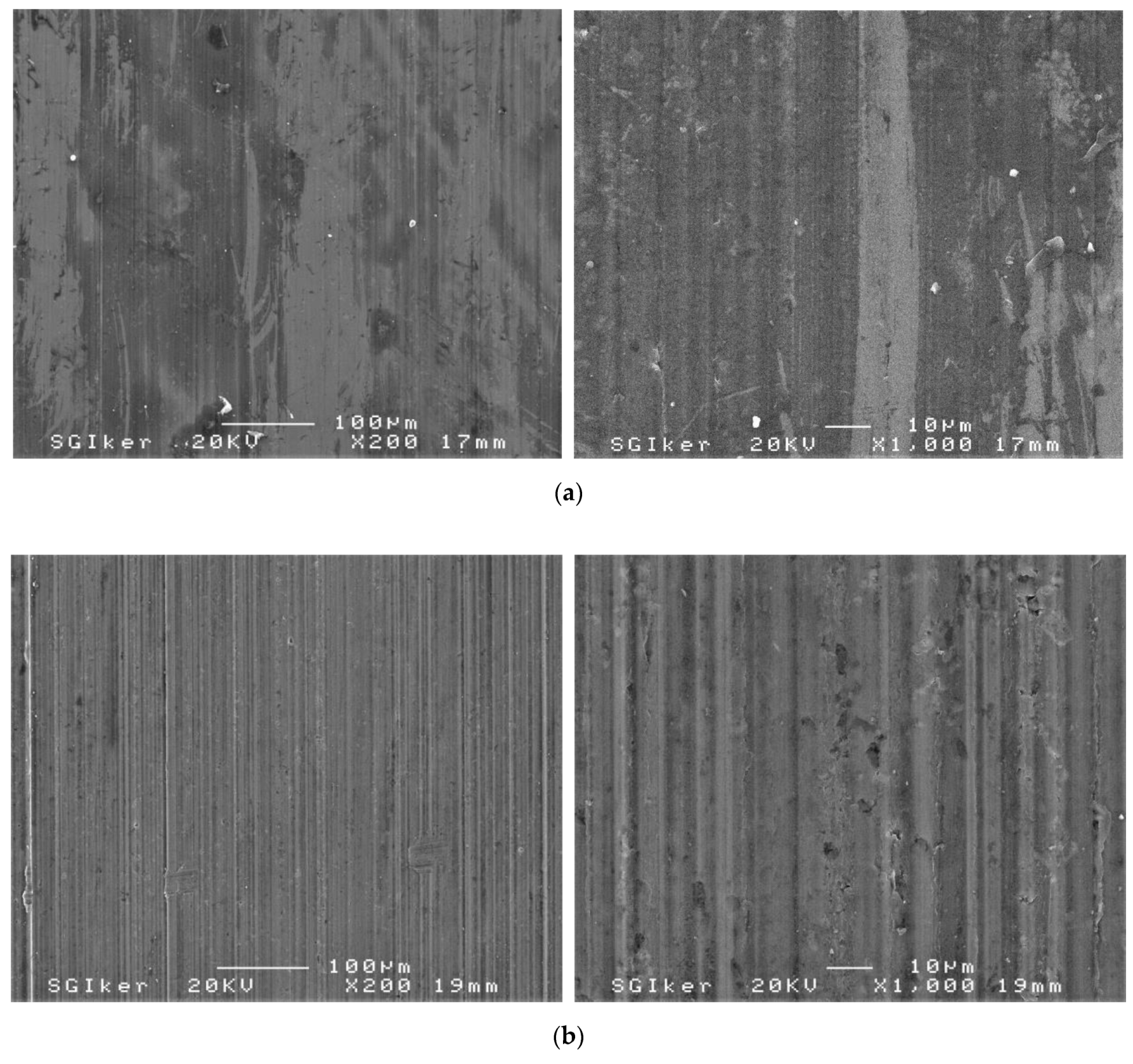
Figure 8.
SEM micrographs that show wear in the AA5083-N0-T200 cam after 200 × 103 rev: (a) upper zone; (b) lower zone.
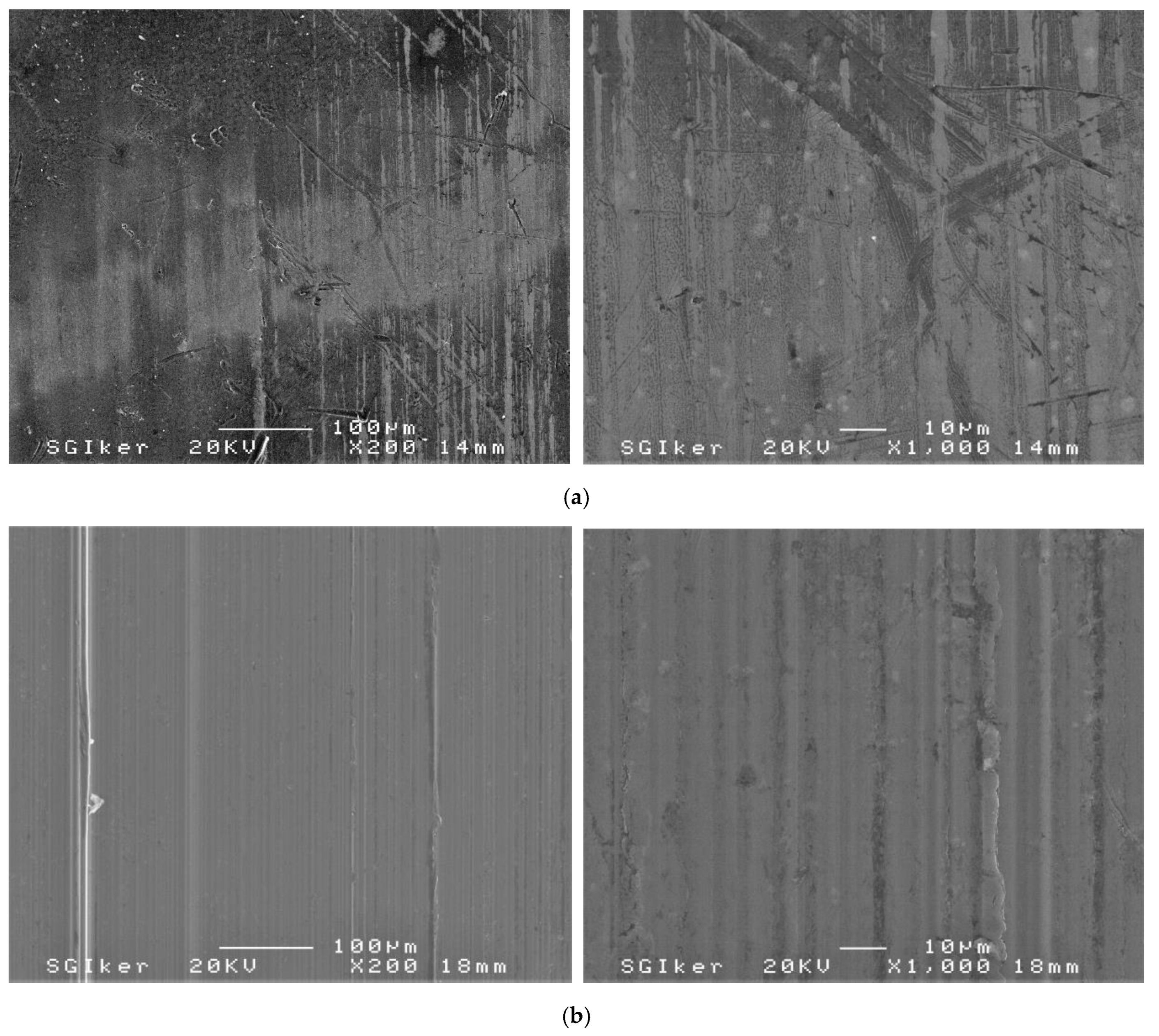
Figure 9.
SEM micrographs that show wear in the AA5083-N2-T200 cam after 200 × 103 rev: (a) upper zone; (b) lower zone.
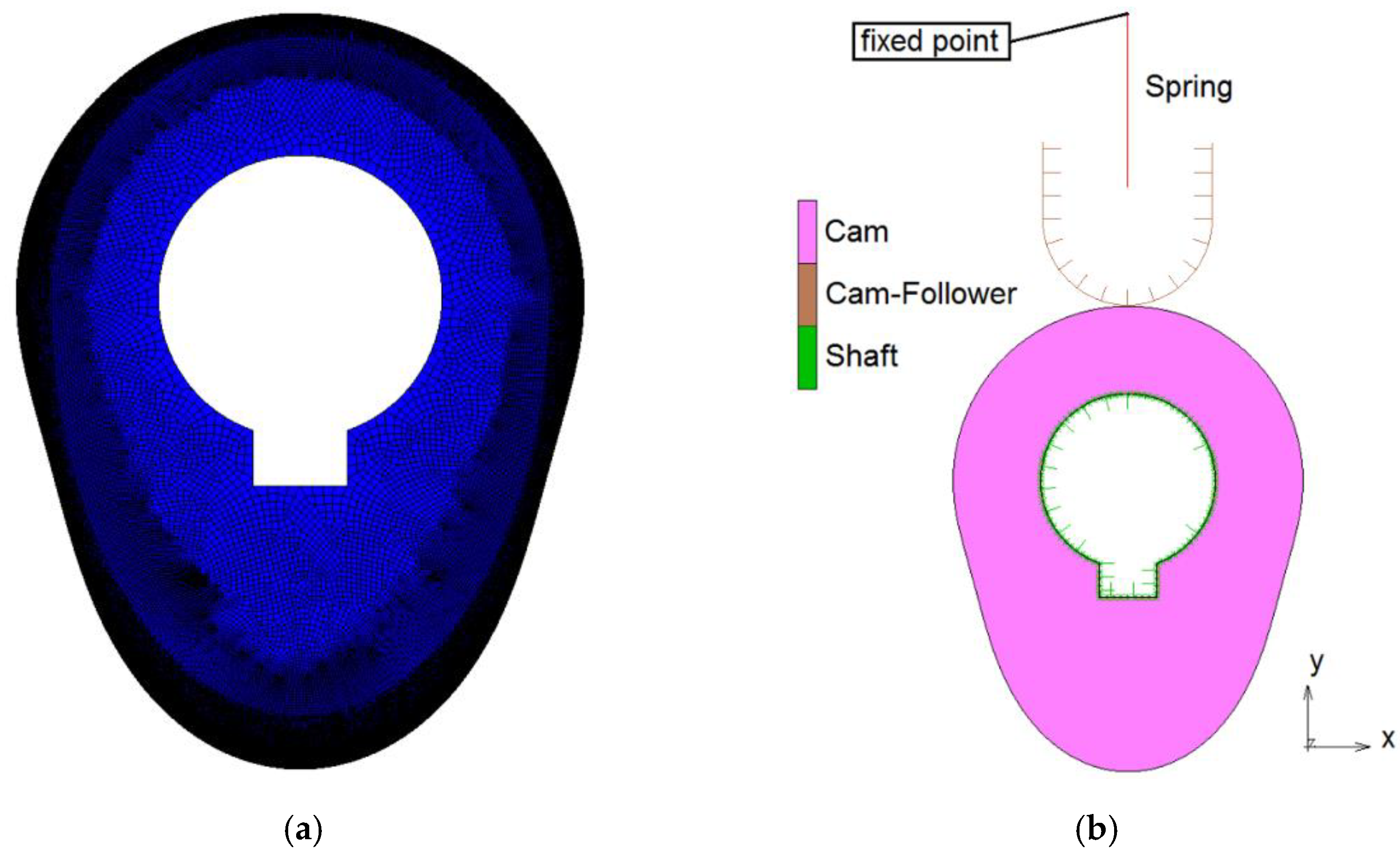
Figure 10.
(a) Meshing of the cam and (b) contact bodies.
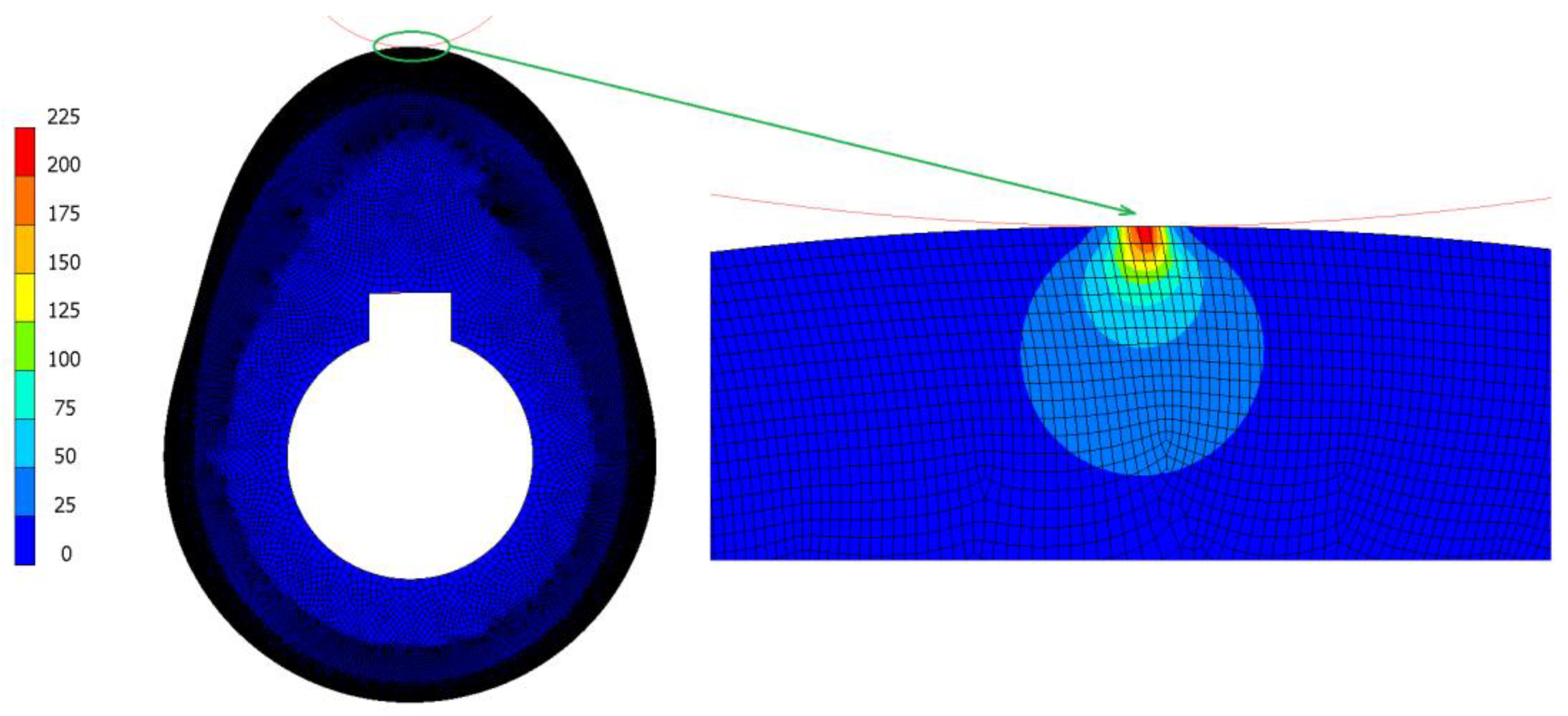
Figure 11.
Equivalent Von-Mises stress (MPa) at the top dead centre.
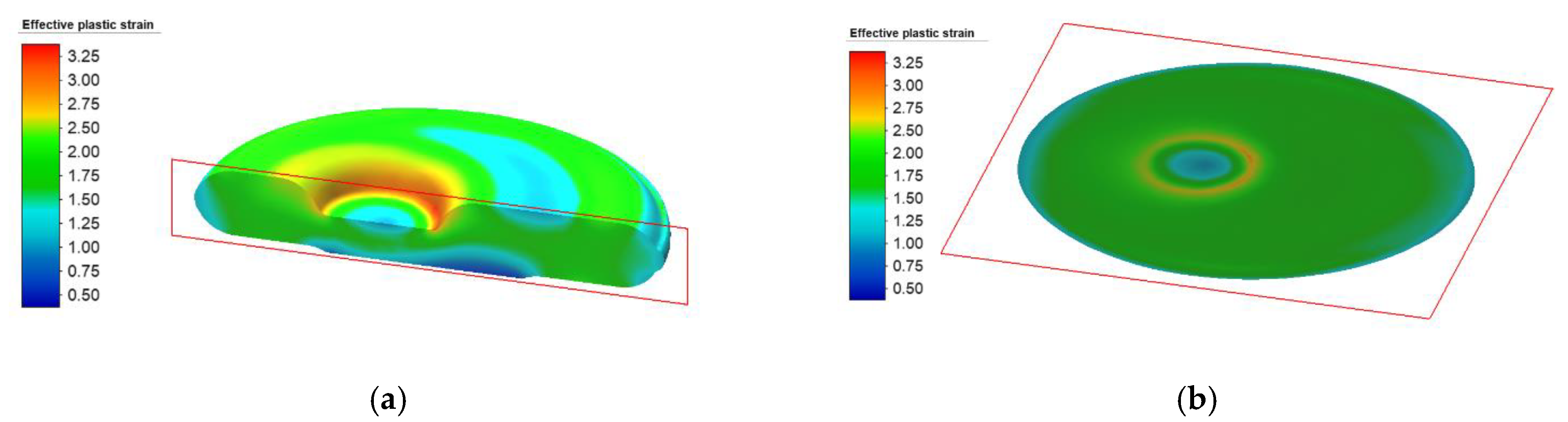
Figure 12.
Effective plastic strain values of cam after the forging process with AA-5083-N0 as a starting material (most unfavourable study case) (a) where the first plane of cut (in red) is a cross-section plane located at the middle of the width of the cam and (b) the second plane of cut (in red) is a longitudinal plane located at the middle of the height of the cam.
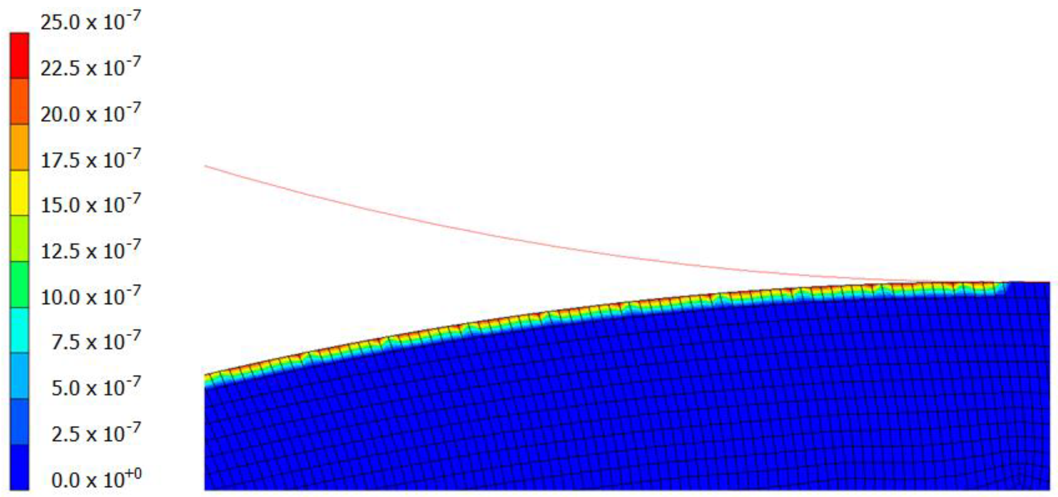
Figure 13.
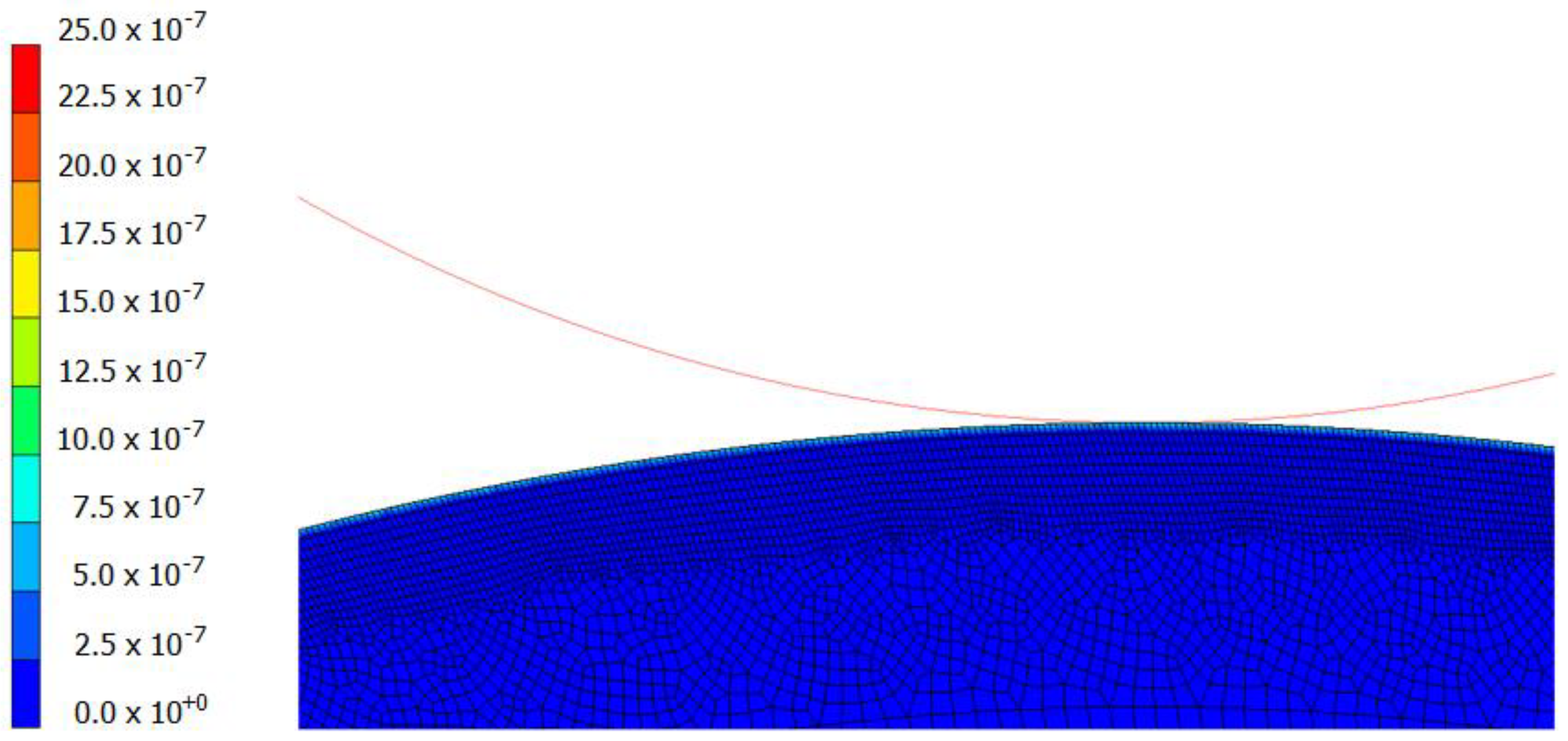
Wear index at the top dead centre for the AA-5083-N2-T200.
Figure 14.
Wear index at the bottom dead centre for the AA-5083-N2-T200.
Table 1.
Loss of volume (mm3) during the wear tests, where the expanded uncertainty values are U (k = 2) = 0.05 mm3 for all cases.
| Study Case | | | |
|---|
| | |
|---|
| AA-5083-N0-T200 | 42.98 | 86.14 | 169.53 |
| AA-5083-N2-T200 | 33.59 | 71.94 | 143.46 |
Table 2.
Dimensional wear coefficients K (MPa−1).
| Study Case | K |
|---|
| AA-5083-T200-N0 | 6.111 × 10⁻⁸ |
| AA-5083-T200-N2 | 5.172 × 10⁻⁸ |
Table 3.
Comparison of loss of volume (mm3) during both the wear tests and FEM, after 200 × 103 rev.
| Study Case |
|
| |
|---|
| AA-5083-N0-T200 | 169.5305 | 170.7504 | 0.71% |
| AA-5083-N2-T200 | 143.4624 | 144.5133 | 0.73% |
© 2020 by the authors. Licensee MDPI, Basel, Switzerland. This article is an open access article distributed under the terms and conditions of the Creative Commons Attribution (CC BY) license (http://creativecommons.org/licenses/by/4.0/).

 ,
, 


