
Chemical and Physical Ionic Liquids in CO2 Capture System Using Membrane Vacuum Regeneration


Departamento de Ingenierías Química y Biomolecular, Universidad de Cantabria, ETSIIT, 39005 Santander, Spain
*
Author to whom correspondence should be addressed.
Membranes 2022, 12(8), 785; https://doi.org/10.3390/membranes12080785
Submission received: 21 July 2022
/
Revised: 12 August 2022
/
Accepted: 12 August 2022
/
Published: 15 August 2022
(This article belongs to the Special Issue Mixed-Matrix Membranes and Polymeric Membranes)
Abstract
:Carbon Capture Utilization and Storage technologies are essential mitigation options to reach net-zero CO2 emissions. However, this challenge requires the development of sustainable and economic separation technologies. This work presents a novel CO2 capture technology strategy based on non-dispersive CO2 absorption and membrane vacuum regeneration (MVR) technology, and employs two imidazolium ionic liquids (ILs), [emim][Ac] and [emim][MS], with different behavior to absorb CO2. Continuous absorption–desorption experiments were carried out using polypropylene hollow fiber membrane contactors. The results show the highest desorption behavior in the case of [emim][Ac], with a MVR performance efficiency of 92% at 313 K and vacuum pressure of 0.04 bar. On the other hand, the IL [emim][MS] reached an efficiency of 83% under the same conditions. The MVR technology could increase the overall CO2 capture performance by up to 61% for [emim][Ac] and 21% for [emim][MS], which represents an increase of 26% and 9%, respectively. Moreover, adding 30%vol. demonstrates that the process was only favorable by using the physical IL. The results presented here indicate the interest in membrane vacuum regeneration technology based on chemical ILs, but further techno-economic evaluation is needed to ensure the competitiveness of this novel CO2 desorption approach for large-scale application.
1. Introduction
Great efforts to reduce carbon dioxide (CO2) emissions from the industrial and energy sectors (decarbonization) are crucial to reach the commitment to have net-zero greenhouse gas emissions by 2050 [1]. In this context, post-combustion Carbon Capture, Utilization, and Sequestration (CCUS) technologies are currently gaining interest due to their potential to significantly capture CO2 from large emission sources, including, on the one hand, thermal and power generation plants, which contribute greatly to the increase of CO2 in the atmosphere, and on the other hand, non-energy industrial sectors, such as the cement, chemical, and steel industries, where there is currently no real alternative to reach net-zero CO2. The different CCUS approaches, depending on the application of the captured carbon dioxide technology, involve the capture of CO2 from the output gas of industrial processes for permanent storage in geological cavities (CCS) [2] or use as a resource for carbon-based products (CCU) [3].
Solvent-based absorption–desorption technology, which typically separates CO2 from flue gas in packing columns, is presented as one of the most mature technologies. Nevertheless, the main challenge is to achieve a reduction in energy consumption for CO2–rich solvent regeneration carried out in the desorption column, which is estimated to constitute 80% of the total carbon capture system energy required [4]. Focusing on this, Membrane Vacuum Regeneration (MVR) technology has been proposed as a promising CO2 desorption process due to its potential for reducing the energy needed for regeneration with respect to conventional packed columns [5,6,7,8]. Using the MVR system, CO2 is desorbed in a hollow fiber membrane contactor (HFMC) from the rich solution by vacuum. The application of vacuum for CO2 desorption decreases the solvent regeneration temperature required and, therefore, the total energy needed for the CO2 capture system [9]. In addition, the lower operating temperatures of MVR technology increase the applicability of polymeric hollow fiber membrane contactors (HFMC), which have advantages, such as low production cost, hydrophobicity, commercial availability, and a wide range of chemical and morphological tunability—but are not suitable for high operating temperatures [4,10].
Until now, the most widely-used solvents in the CO2 desorption process with MVR technology are amine-based solutions, mainly due to the low cost, low viscosity, and high CO2 absorption capacity—even at low CO2 partial pressures [8]. In this context, Kosaraju et al. [11] demonstrated the feasibility of CO2 membrane stripping using commercial PP membrane contactors through long-term running (55-day test). Fang et al. [12], Yan et al. [13], and Wang et al. [14] screened 23 types of alkanolamines for MVR and experimentally evaluated the relationship between solvent composition and MVR efficiency. Listiyana et al. [6] conducted experiments on CO2 desorption in PP HFMC using activated amines to increase the CO2 regeneration efficiency and reduce the cost of the solvent. By indicating the focus on energy saving, Nii et al. [15] showed that MVR technology could effectively employ low-temperature energy or waste heat in power plants. However, several drawbacks have been reported for the amine-based CO2 desorption process, such as an energy intensive regeneration requirement, high absorbent loss, degradability, and corrosiveness of the HFMC, which promote the research of alternative solvents with better properties to address these disadvantages [16].
In this sense, ionic liquids (ILs) are presented as potential alternatives due to their special features for carbon capture, such as their high CO2 uptake capacity, negligible vapor pressure, wide operation liquid temperature range, and tunability [17,18]. ILs are divided into two main categories: non-functionalized room temperature (RTILs) and task specific (TSILs). The main difference between these two types of sorbents is that while RTILs behave like common physical absorbents for gases represented by Henry’s Law constant, TSILs present both physical and chemical absorption and, consequently, may absorb more CO2. However, the solvent regeneration process using TSILs is very energy-intensive due to chemical bonding [19].
Recent trends focused on CO2 desorption by coupled MVR technology using ILs may be resumed in the efforts of: (i) studying IL-based membrane contactors focused on solvent–membrane compatibility (Mulukutla et al. [20] and Bazhenov et al. [21]), and (ii) covering the design, modeling, and simulation for low-temperature CO2 desorption using different ILs to address the influence of operating variables (Lu et al. [22], Simons et al. [23] and Vadillo et al. [10]). Therefore, it is necessary to investigate the influence of IL nature (physical or chemical absorption) in the solvent regeneration performance not only for thermodynamic and kinetic IL properties (e.g., viscosity, CO2 solubility), but also with CO2 desorption process simulations. In this context, experimental data about the CO2 desorption process with MVR technology and ILs with both physical and chemical nature could be helpful to identify the key properties of solvents, considering the extra degree of freedom in ILs design provided by the tunability property [24].
In this work, the ILs, 1-Ethyl-3-methylimidazolium acetate ([emim][Ac]) and 1-Ethyl-3-methylimidazolium methyl sulfate ([emim][MS]), have been chosen as promising candidates as chemical and physical ILs, respectively. The effect of temperature and vacuum level were analyzed on the desorption performance and CO2 desorbed flux. Finally, the overall absorption–desorption system performance was calculated and discussed for both ILs at different operational conditions of solvent temperature, vacuum level, and the addition of water in the ILs. This evaluation would help the reader to recognize different types of ILs, which provides a blueprint for solvent selection in the field of the non-dispersive absorption–desorption process using membrane contactors and vacuum desorption as a promising carbon capture technology.
2. Materials and Methods
2.1. Materials and Characterization
The feed gas of the CO2 capture system was composed of 15% carbon dioxide (99.7, Air LiquideTM, Madrid, Spain and 85% nitrogen (99.9%, Air LiquideTM, Madrid, Spain), which was in the range of typical electro-intensive industries (10–25%) [25].
The IL [emim][MS] (≥95%) was supplied by Sigma AldrichTM and was selected due to its high values of surface tension and contact angle, moderate values of viscosity, and the presence of physical absorption, which potentially decreases the energy consumption during the solvent regeneration process [26]. The process performance was compared with previous works using the IL [emim][Ac] (≥90%) provided by Sigma AldrichTM Darmstadt, Germany; which presents chemical absorption (also called chemisorption) [10]. Table 1 shows the identification of the studied solvents.
To ensure the stability of the ILs for further CO2 capture experiments, the ILs’ decomposition temperatures were calculated by thermogravimetric analysis using a TGA-60H Shimazdu Thermobalance (Izasa, Japan). The viscosity was measured using a rotational viscometer at room temperature. In contrast, in order to evaluate the hydrophobicity/hydrophilicity and wetting behavior of the membranes, the static contact angles between the membrane and different ILs were estimated by the sessile liquid drop method using the contact angle quantification system (DSA25, Krüss, Hamburg, Germany). The contact angles were calculated at room temperature and atmospheric pressure. Adjustment of the picolitre dispenser (0.5 mm syringe) and camera image were also done before each component measurement. Then, a 2.0 µL drop with the desired component was deposited on the membrane’s surface at various sites (at least 5 points). Each value was obtained using the software provided through image recognition, and the average contact angle value was then considered.
2.2. Membrane Contactor
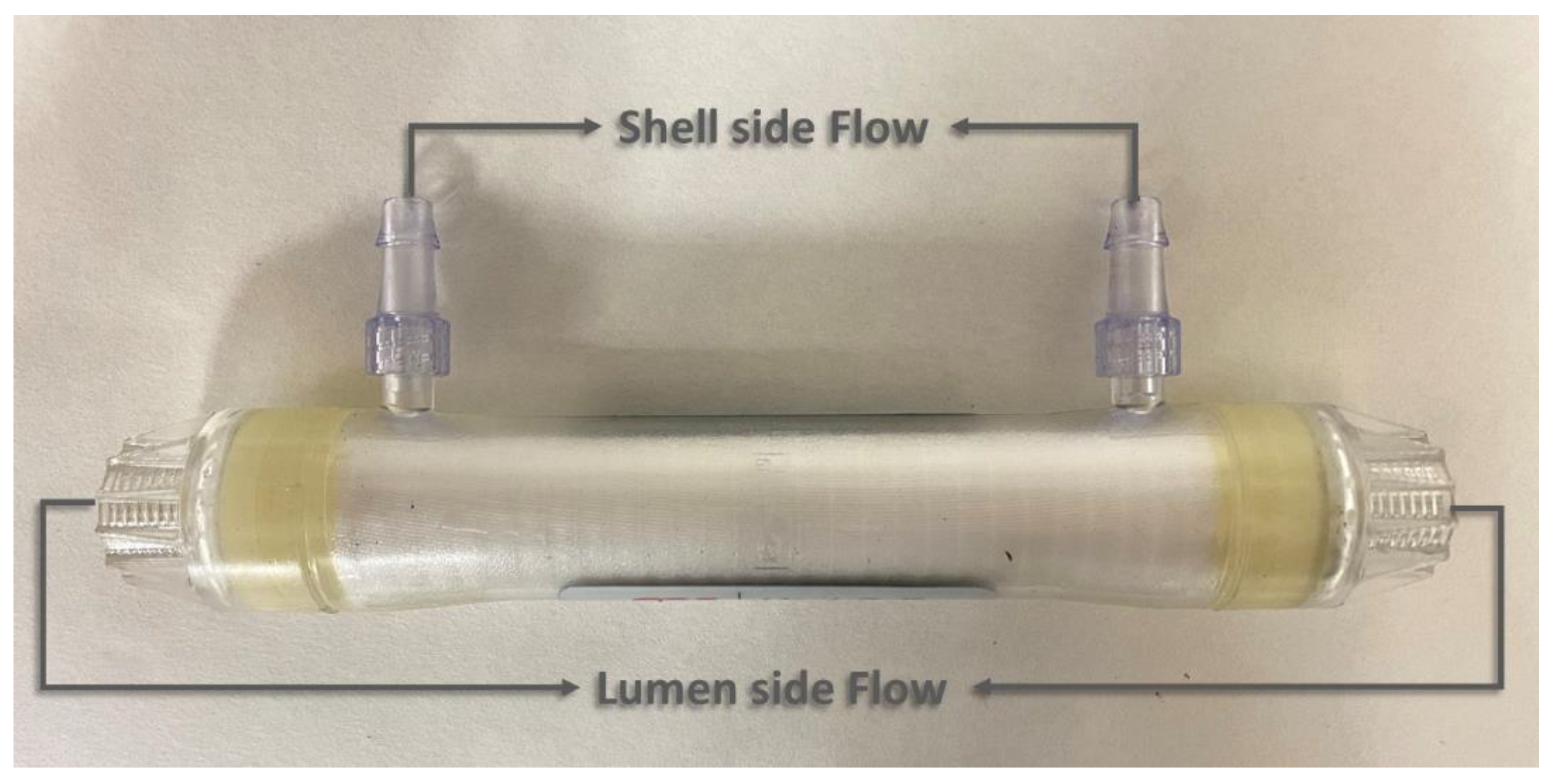
A hydrophobic polypropylene HFMC (1 × 5.5 MiniModuleTM) supplied by Liqui-CelTM (3M Madrid, Spain) was used in parallel flow for the continuous absorption–desorption process. The module consists of mesoporous polypropylene hollow fibers with 40% porosity and a mean pore diameter of 0.04 μm. Figure 1 describes the flow configuration and Table 2 shows the specifications of the commercial membrane module used in this work.
2.3. Experimental Set-Up
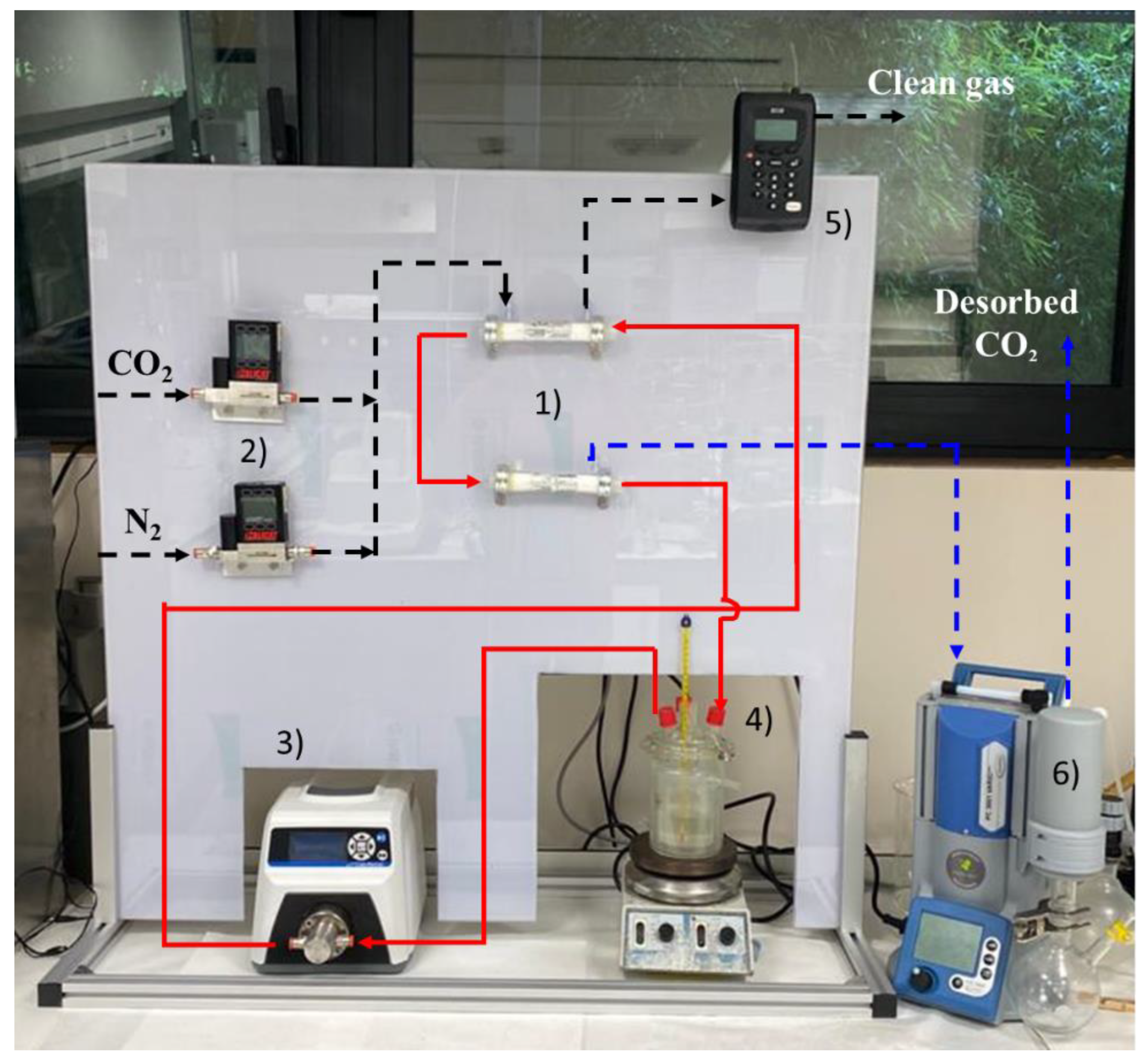
In this section, the process units used for the CO2 capture experimental plant based on non-dispersive absorption using ionic liquids and MVR technology was described. Figure 2 shows a picture of the experimental system, consisting of:
- (1)
- Two hollow fiber membrane contactors that can operate interconnected, for both the non-dispersive absorption of the CO2 from the feed gas and the CO2 desorption by applying vacuum.
- (2)
- Two mass flow controllers (Alicat ScientificTM, Duiven, The Netherlands MC-gas mass flow controller Tucson, AZ, USA) to control the flows coming from the pure gas cylinders (CO2 and N2) to set the concentration and flow of the feed gas.
- (3)
- A digital gear pump (Cole-Parmer Gear Pump SystemTM Vernon Hills, IL, USA, Mount Prospect, Vernon Hills, IL, USA, Benchtop Digital Drive, 0.017 mL·rev−1, 220 VAC, Saint Louis, MO, USA) to drive and maintain constant liquid flow during the continuous absorption–desorption process.
- (4)
- A closed vessel of tempered borosilicate glass (PyrexTM, Paris, France) to contain and keep constant the temperature of the IL by means of a heater-stirrer.
- (5)
- Two gas analyzers (GeotechTM, G110 0-100%, Suffolk, UK) to measure the mass flow rate and CO2 concentration of the gas streams (feed gas, clean gas, and desorbed CO2 output). The analyzer is based on non-dispersive infrared spectroscopy (NDIR). The CO2 concentration in the output gas stream was monitored using the NGA Win-Control software.
- (6)
- A vacuum pump, with condenser included (VacuubrandTM, PC 3001 VARIO PRO, Wertheim, Germany), to set the gas phase of the membrane contactor (used for CO2 desorption) at the desired vacuum pressure.
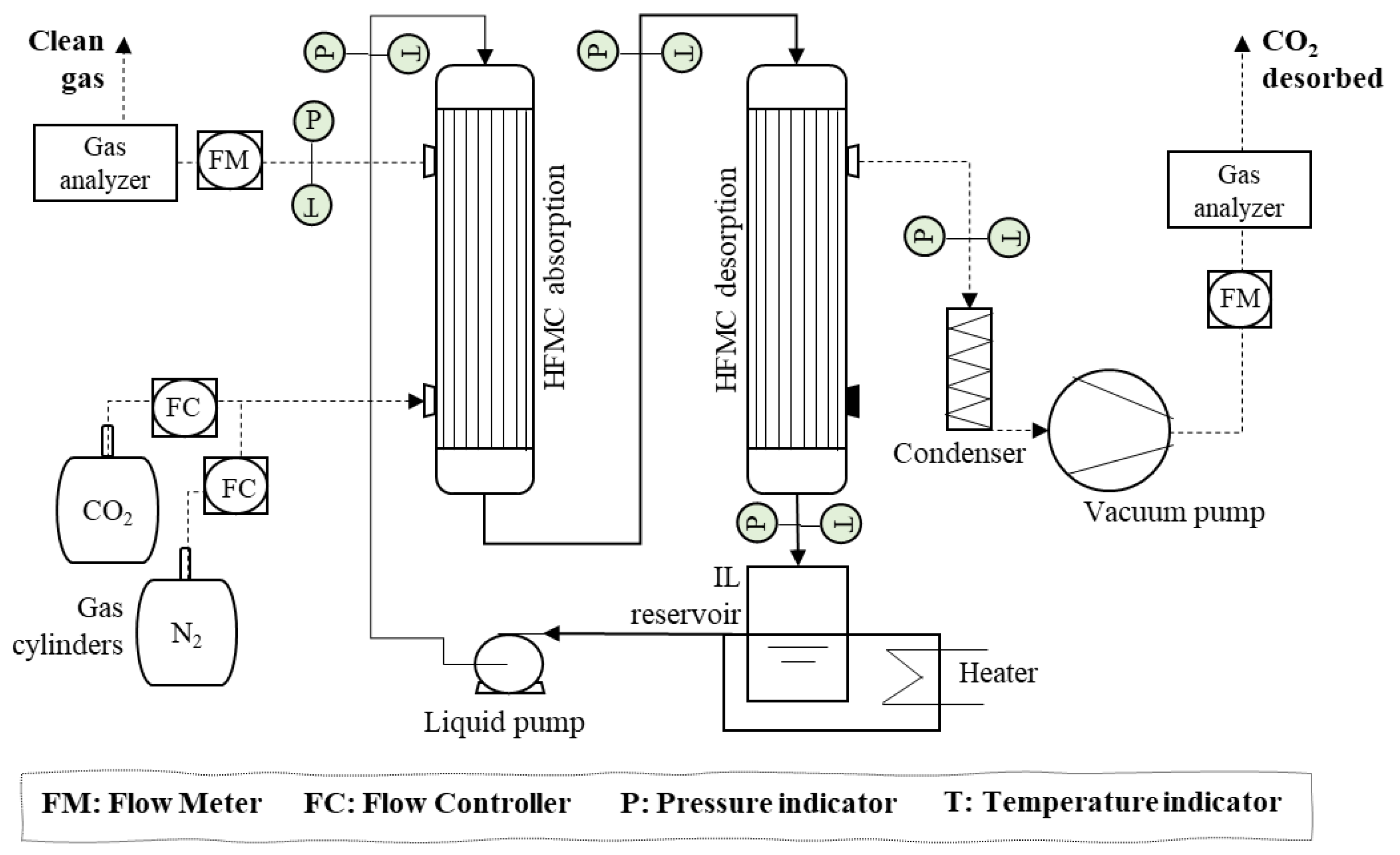
In addition, to visualize the system more clearly, Figure 3 shows the flow diagram of the continuous CO2 non-dispersive absorption–desorption plant using membrane contactors with the HFMC configuration.
The IL was recirculated through the lumen side of both HFMCs (absorber and desorber) in a closed loop. The solvent flow rate was kept constant by a digital gear pump. A heater was used in order to provide isothermal conditions during the continuous absorption–desorption process. The feed gas mixture was introduced through a counter-current at nearly atmospheric pressure across the HFMC absorber shell side in open-loop conditions with a constant flow rate, while the IL passes through the lumen side of the module absorbing the CO2. The CO2-rich IL was pumped into the HFMC desorber lumen side where the CO2 was transferred through the gas-filled membrane pores because of the shell side’s reduced pressure that was generated by the vacuum pump. The experiments of the continuous absorption–desorption process were running until the CO2 concentration on both gas outputs (clean gas and CO2 desorbed) were constant. Moreover, the experiments were carried out three times in order to ensure the results’ reproducibility. The data presented in the manuscript were the average values for the set of three experiments, with an experimental error within ±5%. Table 3 shows the process operating conditions.
2.4. Data Analysis
To analyze the performance of the CO2 desorption process based on MVR technology and its effect on the overall CO2 capture process, three parameters were mainly studied throughout the work.
- (1)
- The CO2 desorption efficiency is calculated by Equation (1), where αrich and αlean are the CO2 loading in the IL (molCO2·mol_IL−1) before and after one pass of IL through the HFMC desorber, respectively.
- (2)
- The overall CO2 capture efficiency, which is defined as the concentration difference in the HFMC absorber between the feed gas and the clean gas, is obtained by Equation (2), where C(CO2,g)in (mol CO2·L−1 gas) is the CO2 concentration in the feed gas and C(CO2,g)out (mol CO2·L−1 gas) is the CO2 concentration at the outlet of the module. The overall CO2 capture efficiency is important in order to study the influence of the MVR technology on the continuous absorption–desorption process.
- (3)
- The CO2 desorbed flux (GV, mol·h−1 m−2) is estimated by Equation (3), where FV is the CO2 flow rate desorbed from the HFMC desorber measured on the vacuum pump output (L·h−1), vm is the molar volume of CO2 in ideal gas conditions (L·molCO2-1), and A is the specific membrane area (m2).
3. Results and Discussion
The imidazolium ILs, [emim][Ac] and [emim][MS], were studied in this work as chemical and physical CO2 absorbents, respectively, for non-dispersive absorption technology using ionic liquid and MVR. In this section, the CO2 absorption capacity for each IL was discussed according to the equilibrium isotherms reported in the literature. Moreover, the experimental results of the absorption–desorption process operating at different MVR operating conditions (desorption vacuum pressures and solvent temperatures) were analyzed.
3.1. Absorption Properties
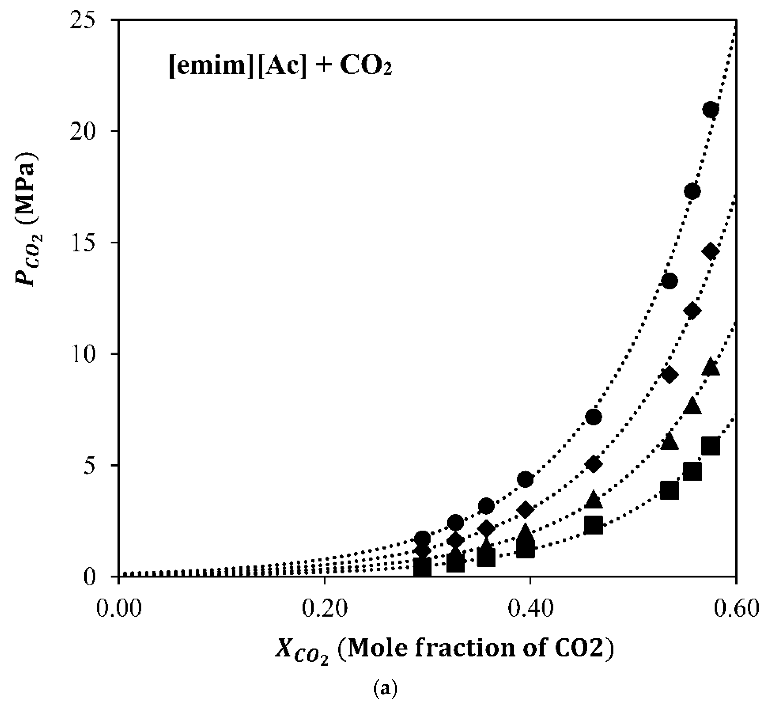
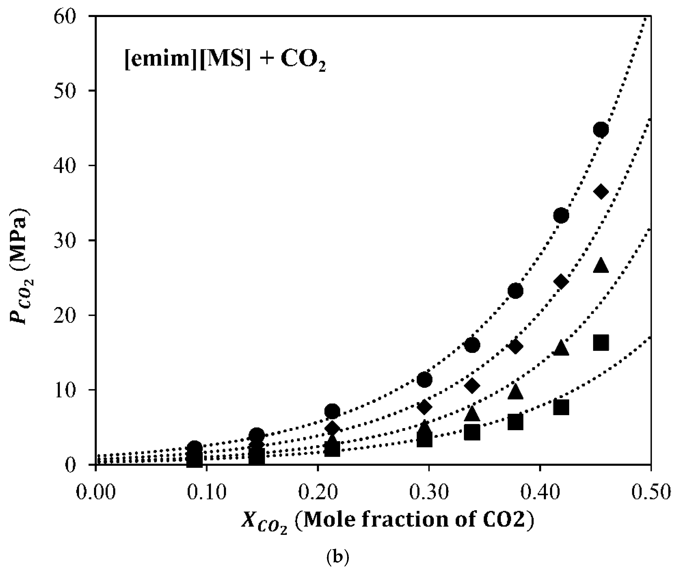
The equilibrium isotherms of the [emim][Ac]-CO2 and [emim][MS]-CO2 interactions were experimentally studied by Shifflet et al. [27] and Yim et al. [28]. Figure 4 shows the P–X diagram of CO2 solubility at different temperatures in both ILs used in this work.
IL [emim][MS] is considered a suitable absorbent for this system at higher partial pressures based not only on its good solvent properties (low volatility and very low viscosity), but also based on its behavior as a physical absorbent of CO2. IL [emim][Ac] is a better overall absorbent when attending to its isotherms and is specifically better at low CO2 partial pressures (where post-combustion CO2 capture processes work) due to the more thermodynamically favorable chemical reaction. Although the chemical IL, [emim][Ac], seems to be a better solvent for CO2 capture applications, the continuous absorption–desorption process not only depends on the CO2 absorption capacity of the solvent, but also on the MVR operation conditions (mainly vacuum pressure and liquid temperature), the CO2-IL chemical and/or physical interactions, and the contactor characteristics, such as membrane geometry and fluid dynamics [29]. In order to investigate the regeneration operation conditions and the IL nature influence on the CO2 desorption performance, a parametric study was considered in the next section.
3.2. ILs Characterization
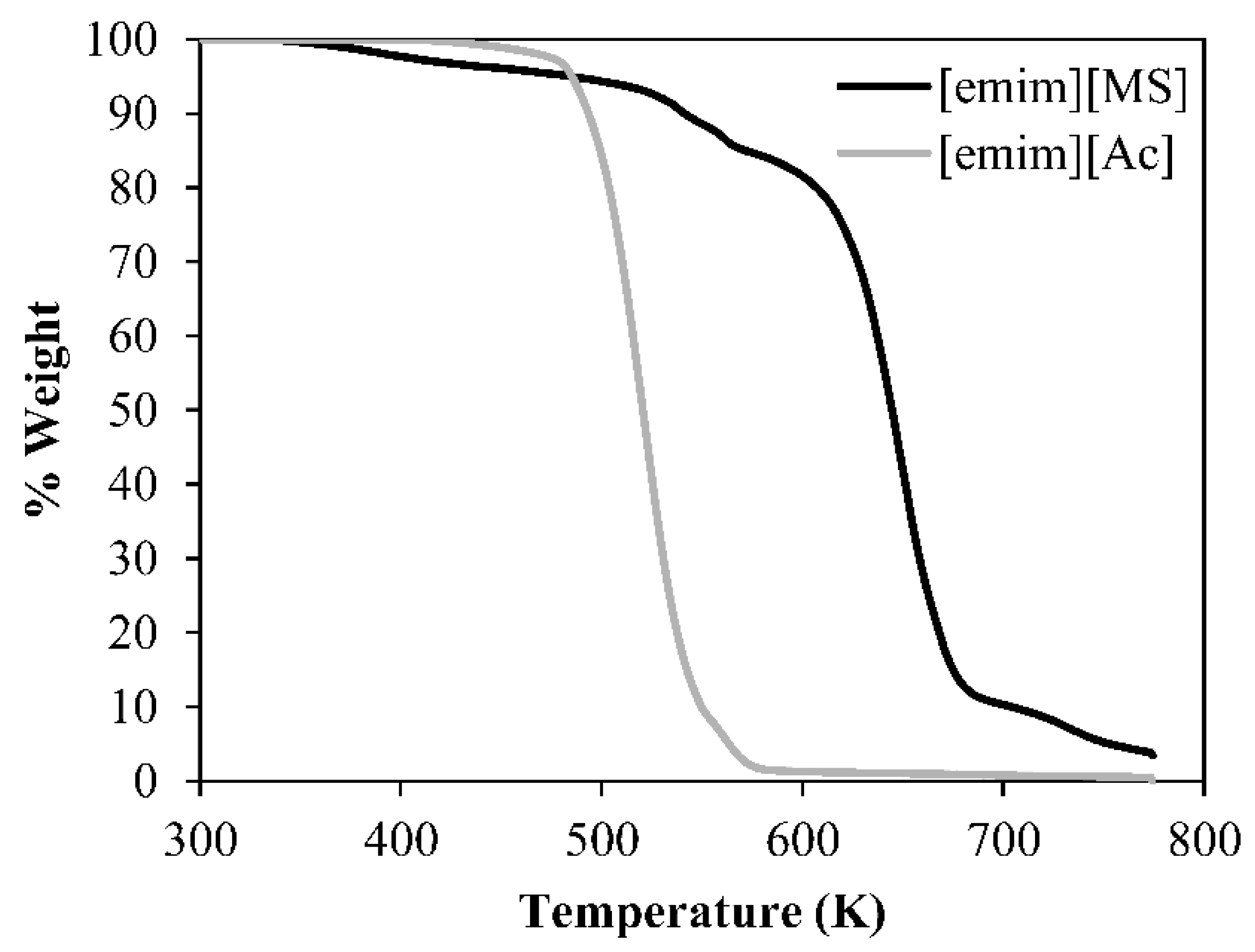
Firstly, TGA analysis shows that the ILs remain without reducing more than 5% of their weight up to temperatures of 450 K and 470 K for [emim][MS] and [emim][Ac], respectively, as depicted in Figure 5. These issues confirm the ionic liquids’ stability and their capacity to carry out the absorption–desorption processes under real conditions without damage and degradation.
Moreover, the viscosity of both ILs was measured to ensure the good quality and purity of the samples. In addition, these values were compared with the previous data reported in the literature [30,31]. Finally, the contact angle demonstrates the hydrophilic or hydrophobic characteristics of the membranes with the ILs. Hydrophilic surfaces show low water contact angle (<90°) and hydrophobic surfaces show high water contact angle values. Table 4 summarizes the viscosity and measured contact angle values of both the [emim][Ac] and [emim][MS] ILs. Thus, it is possible to say that the polypropylene hollow fiber membranes used in this work present a hydrophobic character with the ionic liquids. Therefore, membrane wetting is highly avoided.
3.3. Parametric Study of Desorption Process
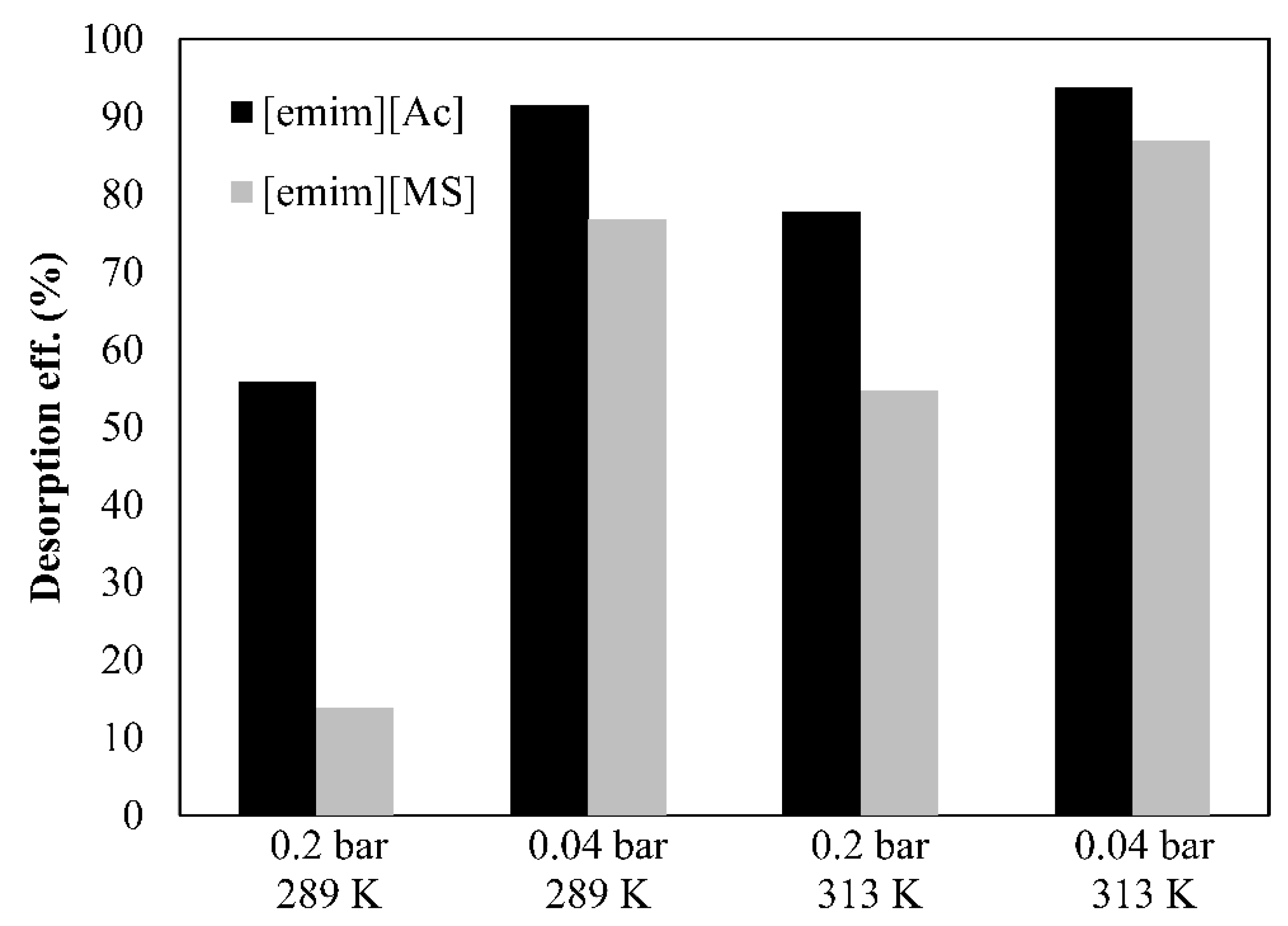
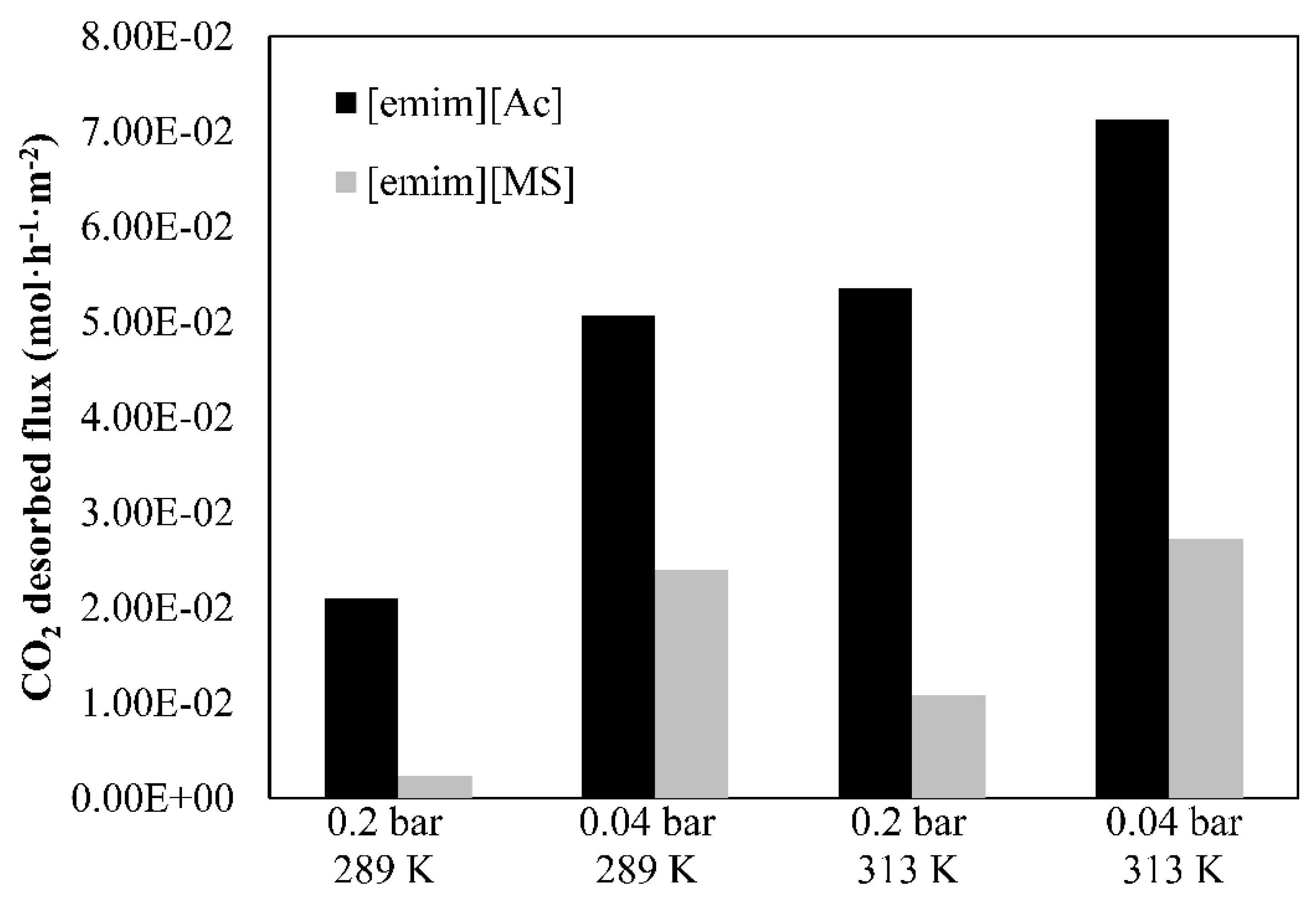
The following part of this study discusses the experimental results (CO2 desorption performance and CO2 desorbed flux) with both the chemical and physical ILs at different operating conditions of the vacuum regeneration system. The process efficiency and the CO2 desorbed flux results, which vary with the operating vacuum pressure and liquid temperature, were analyzed in Figure 6 and Figure 7, respectively.
On the one hand, a lower CO2 partial pressure (higher vacuum applied) on the permeate side of the HFMC desorber promotes the CO2 mass transfer driving force through the membrane, which increases the desorption performance as a result of the higher CO2 desorbed flux. On the other hand, the CO2 desorption process efficiency and the CO2 desorbed flux increase with a higher solution temperature. This behavior in both ILs could be explained by the lower viscosity (µ) at higher temperatures, which increases the diffusivity of CO2 in the absorbent since the mass transfer coefficient is controlled by the liquid-phase mass transfer resistance. Moreover, the CO2 partial pressure increases because of the higher concentration gradient at higher temperatures, leading to an increase of the CO2 desorbed flux.
From these experiments, it is clear that the vacuum level and liquid temperature should be as high as possible. However, two process limitations have to be taken into account in order to avoid HFMC operational problems: (i) the pressure applied by the vacuum pump in the permeate side was recommended to be greater than 0.035 bar in order to avoid wetting phenomena and (ii) temperatures higher than 310–320 K may require more resistant membrane materials due to thermal and chemical constraints of the commercial polypropylene HFMC used in our work. Physical IL [emim][MS] showed lower CO2 desorption performance and CO2 desorbed flux at the experimentally-tested temperatures (289-313 K) than the corresponding IL [emim][Ac]. This could be explained due to the lower CO2 loading capacity of the physical IL that leads to a lower CO2 driving force through the membrane.
Furthermore, only chemical [emim][Ac] was able to reach the target of 90% desorption efficiency for vacuum regeneration using the commercial PP-HFMC at the operating conditions (module characteristics given in Table 1). Two main points, which are related to the vacuum pressure effect, could be concluded from the results shown in Figure 6 and Figure 7: (i) Chemical IL [emim][Ac] was less sensitive to vacuum pressure conditions, which could be explained by the fact that the chemical IL requires more energy to break the CO2–IL chemical bond, and (ii) physical IL [emim][MS] required the application of higher vacuum than the corresponding IL, [emim][Ac], to reach the same desorption efficiency, which increased the energy consumption for both the vacuum pump and compressor unit operation, resulting in a higher overall cost of the CO2 vacuum desorption process [32].
In summary, the chemical IL, [emim][Ac], shows a better CO2 desorption performance and higher CO2 desorbed flux at different vacuum pressures and liquid temperatures. This could mainly be explained due to the larger capacity of CO2 to be absorbed into chemical IL by chemisorption, which increases the CO2 driving force through the membrane in the CO2 vacuum desorption process. However, the total energy consumption of the solvent regeneration with chemical ILs, such as [emim][Ac], may be expected to be higher than physical ILs, such as [emim][MS], due to the extra energy required to reverse the CO2–IL chemical reaction as previously reported [33,34].
3.4. ILs Comparison in the Overall CO2 Capture
The desorption process efficiency and the CO2 desorbed flux were evaluated in the previous section at different operation conditions in a continuous steady-state absorption–desorption CO2 capture system by using chemical IL [emim][Ac] and physical IL [emim][MS]. In this section, the influence of the CO2 desorption stage (based on MVR technology) in the overall CO2 capture system was evaluated by Equation (3), which was described in Section 2.4 (Data Analysis). The membrane contactor specifications and the operational conditions were described in Table 2 and Table 3.
Figure 8 shows the experimental results of the steady state absorption–desorption system at two representative operating conditions in order to evaluate the influence of both solvent temperature (289 K and 313 K) and CO2 desorption vacuum pressure (0.2 bar and 0.04 bar) on the overall CO2 capture efficiency for each IL analyzed in this work.
For chemical IL [emim][Ac], higher solvent temperatures and CO2 desorption vacuum pressures enhanced the overall CO2 capture efficiency from 29% to 61%. Moreover, the temperature contribution on the CO2 capture performance was more significant than the CO2 desorption vacuum pressure (Pv) since the lower viscosity of the [emim][Ac] at higher temperatures and the chemisorption effect increases the CO2 absorption capacity. For physical IL [emim][MS], higher vacuum applied in the MVR process increased the overall CO2 capture efficiency from 12% to 21%. However, at the same operating vacuum pressure, the solvent temperature effect on the overall CO2 capture performance was not significant. This could be explained because of both: (i) the decrease in viscosity at the studied temperatures (289 and 313 K, respectively) was less considerable in the CO2 absorption capacity and (ii) the absence of CO2–IL chemical interactions.
Previous studies of the single absorption process (without desorption technology) have reported efficiencies of 20–35% with chemical IL [emim][Ac] [35] and 10–12% with physical IL [emim][MS] [31]. Furthermore, in this work, the non-dispersive absorption using ionic liquids and vacuum regeneration, at the most favorable operating conditions studied (0.04 bar and 313 K), increase the CO2 capture performance up to 61% and 21%, respectively, which represents a percentage increase compared with the only-absorption process of 26% for [emim][Ac] and 9% for [emim][MS].
Although better absorption–desorption performance is obtained operating at the highest possible temperature due to the lower viscosity of the ILs, the operating temperature was kept below 315 K according to the specifications of the commercial membrane module used in order to avoid chemical or thermal degradation. Therefore, the option of using aqueous [emim][Ac] and [emim][MS] was checked to decrease the solvent viscosities, thereby keeping the temperature in the operational range.
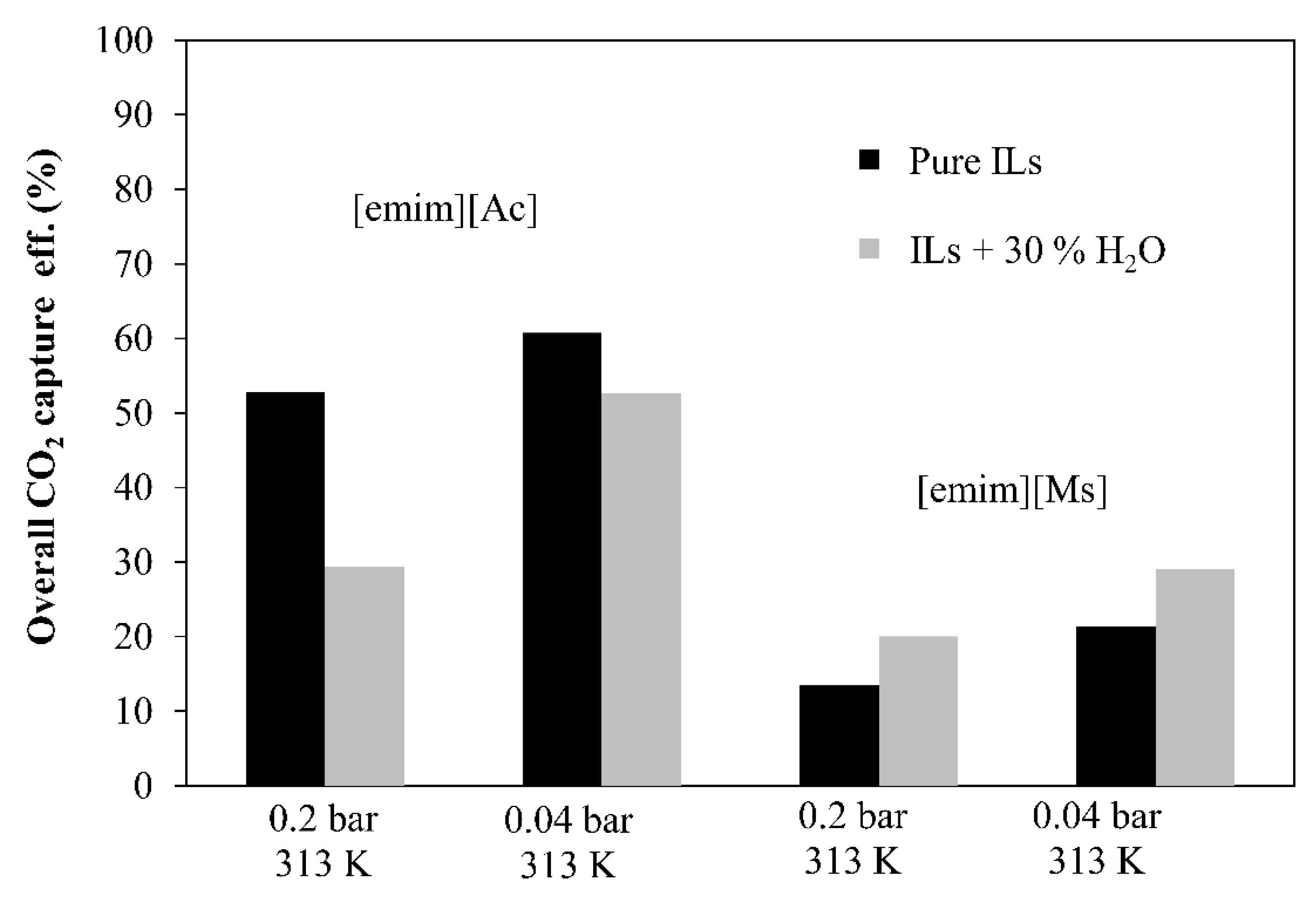
3.5. Influence of IL Water Content in the Process Performance
In this section, experiments were carried out to investigate the effect on the continuous steady-state absorption–desorption process of 30%-vol. water content in the ILs. The overall CO2 capture efficiency was evaluated in Figure 9 at a liquid temperature of 313 K and different vacuum pressures (0.2 and 0.04 bar) by Equation (3) described in Section 2.4 (Data Analysis).
The results indicate that pure IL [emim][Ac] and aqueous IL [emim][MS] were the most favorable for the overall absorption–desorption process performance. Aqueous [emim][MS] physically absorbed CO2 and the CO2 diffusion in the IL was dominant mainly due to the viscosity. In this context, the reduction of viscosity provided by the addition of water to the solvent resulted in an increase of 10% in the values of overall CO2 capture efficiency. Pure IL [emim][MS] has a higher viscosity, which increases the CO2 mass transfer resistance in the liquid side and results in a lower CO2 diffusivity [34]. However, unlike IL [emim][MS], IL [emim][Ac] chemically absorbed CO2 and the reaction rate was dominant in the CO2 absorption capacity compared to the effect of water addition. Furthermore, pure IL [emim][Ac] may provide a higher reaction rate and thus decrease the mass transfer resistance to the liquid side.
4. Conclusions
The main objective has been to study the behavior of ILs with different natures as CO2 absorbents in terms of process performance. The chemical IL, [emim][Ac], and the physical, [emim][MS], were chosen as representative ILs for this study.
The influence on the CO2 desorption efficiency and CO2 desorbed fluxes for different operating conditions has been studied for both ILs. In general, higher temperature and vacuum applied are beneficial to the overall process performance and CO2 desorbed flux. In particular, the chemical IL, [emim][Ac], showed better CO2 desorption performance and higher CO2 desorbed flux than physical IL [emim][MS] at the operating conditions studied. The maximum CO2 desorption efficiencies obtained in this work were 92% and 83% for chemical IL [emim][Ac] and physical IL [emim][MS], respectively. Both performances were at 0.04 bar vacuum pressure, 313 K temperature, and a 60 mL·min−1 liquid flow rate.
Moreover, the overall CO2 capture efficiency was evaluated in order to analyze the influence of vacuum regeneration on the continuous absorption–desorption process at different liquid temperatures and vacuum pressures. Higher CO2 capture efficiency was reached for both ILs at the lowest desorption pressure (0.04 bar) and the highest liquid temperature (313 K) studied in this work. The CO2 capture efficiencies were 61% and 21% for chemical IL [emim][Ac] and physical IL [emim][MS], respectively. Moreover, the addition of water to reduce the ILs viscosity was evaluated in terms of CO2 absorption–desorption system performance. The results indicated that aqueous physical IL [emim][MS] increases the CO2 capture while aqueous chemical IL [emim][Ac] decreases the process performance due to the loss of chemical reaction potential by adding water. However, the study of the counterbalance effect of water content into ILs requires further study since water content could significantly affect the CO2 mass transfer through the membrane, as concluded in this work.
As a whole, the process performances of the chemical IL seem to be better than that of the physical IL in the continuous absorption–desorption CO2 capture system, while physical ILs could be considered as promising energy-saving absorbents for CO2 capture by designing more advanced physical ILs capable of absorbing more CO2.
From the viewpoint of scale-up, coupled membrane contactors, IL-based processes were addressed as a process intensification for CO2 capture. However, more studies of the continuous absorption–desorption systems are needed to drive the industrial implementation and commercial viability of non-dispersive absorption technology using ionic liquids and vacuum regeneration.
Author Contributions
Investigation, J.M.V. and G.D.-S.; Conceptualization, J.M.V., A.G. and A.I.; Validation, J.M.V. and G.D.-S.; Methodology, G.D.-S., L.G.-C. and A.G.; Formal analysis: J.M.V.; Data curation, J.M.V. and G.D.-S.; Formal analysis, J.M.V.; Validation, G.D.-S.; Writing—original draft, J.M.V.; Writing—review & editing, G.D.-S., L.G.-C., A.G. and A.I.; Supervision, L.G.-C., A.G., A.I.; Funding acquisition, A.G. and A.I.; Project administration, A.G. and A.I. All authors have read and agreed to the published version of the manuscript.
Funding
This research was funded by Spanish State Research Agency (AEI), through the projects PID2019-108136RB-C31 and PID2020-112845RB-I00 (AEI/10.13039/501100011033). J.M.V. thanks the Concepción Arenal postgraduate research grant from the University of Cantabria.
Institutional Review Board Statement
Not applicable.
Informed Consent Statement
Not applicable.
Data Availability Statement
Not applicable.
Conflicts of Interest
The authors declare no conflict of interest.
References
- Tsiropoulos, I.; Nijs, W.; Tarvydas, D.; Ruiz Castello, P. Towards Net-Zero Emissions in the EU Energy System by 2050, EUR 29981 EN; Publications Office of the European Union: Luxembourg, 2020; ISBN 978-92-76-13097-0. [Google Scholar]
- Rúa, J.; Bui, M.; Nord, L.O.; Mac Dowell, N. Does CCS Reduce Power Generation Flexibility? A Dynamic Study of Combined Cycles with Post-Combustion CO2 Capture. Int. J. Greenh. Gas Control 2020, 95, 102984. [Google Scholar] [CrossRef]
- Díaz-Sainz, G.; Alvarez-Guerra, M.; Solla-Gullón, J.; García-Cruz, L.; Montiel, V.; Irabien, A. Catalyst Coated Membrane Electrodes for the Gas Phase CO2 Electroreduction to Formate. Catal. Today 2020, 346, 58–64. [Google Scholar] [CrossRef]
- Lee, H.J.; Kim, M.K.; Park, J.H. Decompression Stripping of Carbon Dioxide from Rich Monoethanolamine through Porous Hydrophobic Modified Ceramic Hollow Fiber Membrane Contactor. Sep. Purif. Technol. 2020, 236, 116304. [Google Scholar] [CrossRef]
- Lau, H.S.; Lau, S.K.; Soh, L.S.; Hong, S.U.; Gok, X.Y.; Yi, S.; Yong, W.F. State-of-the-Art Organicand Inorganic-Based Hollow Fiber Membranes in Liquid and Gas Applications: Looking Back and Beyond. Membranes 2022, 12, 539. [Google Scholar] [CrossRef]
- Intan Listiyana, N.; Rahmawati, Y.; Nurkhamidah, S.; Rofiq Syahnur, H.; Zaelana, Y. CO2 Desorption from Activated DEA Using Membrane Contactor with Vacuum Regeneration Technology. In Proceedings of the 24th Regional Symposium on Chemical Engineering (RSCE 2017), Semarang, Indonesia, 15–16 November 2007; Volume 156. [Google Scholar] [CrossRef]
- He, Q.; Xi, J.; Wang, W.; Meng, L.; Yan, S. CO2 Absorption Using Biogas Slurry: Recovery of Absorption Performance through CO2 Vacuum Regeneration. Int. J. Greenh. Gas Control 2017, 58, 103–113. [Google Scholar] [CrossRef]
- Vadillo, J.M.; Gomez-Coma, L.; Garea, A.; Irabien, A. Hollow Fiber Membrane Contactors in CO2 Desorption: A Review. Energy Fuels 2021, 35, 111–136. [Google Scholar] [CrossRef]
- Albarracin Zaidiza, D.; Belaissaoui, B.; Rode, S.; Favre, E. Intensification Potential of Hollow Fiber Membrane Contactors for CO2 Chemical Absorption and Stripping Using Monoethanolamine Solutions. Sep. Purif. Technol. 2017, 188, 38–51. [Google Scholar] [CrossRef]
- Vadillo, J.M.; Gómez-coma, L.; Garea, A.; Irabien, A. CO2 Desorption Performance from Imidazolium Ionic Liquids by Membrane Vacuum Regeneration Technology. Membranes 2020, 10, 234. [Google Scholar] [CrossRef]
- Kosaraju, P.; Kovvali, A.S.; Korikov, A.; Sirkar, K.K. Hollow Fiber Membrane Contactor Based CO2 Absorption-Stripping Using Novel Solvents and Membranes. Ind. Eng. Chem. Res. 2005, 44, 1250–1258. [Google Scholar] [CrossRef]
- Fang, M.; Wang, Z.; Yan, S.; Cen, Q.; Luo, Z. CO2 Desorption from Rich Alkanolamine Solution by Using Membrane Vacuum Regeneration Technology. Int. J. Greenh. Gas Control 2012, 9, 507–521. [Google Scholar] [CrossRef]
- Yan, S.; Fang, M.; Wang, Z.; Luo, Z. Regeneration Performance of CO2-Rich Solvents by Using Membrane Vacuum Regeneration Technology: Relationships between Absorbent Structure and Regeneration Efficiency. Appl. Energy 2012, 98, 357–367. [Google Scholar] [CrossRef]
- Wang, Z.; Fang, M.; Pan, Y.; Yan, S.; Luo, Z. Amine-Based Absorbents Selection for CO2 Membrane Vacuum Regeneration Technology by Combined Absorption-Desorption Analysis. Chem. Eng. Sci. 2013, 93, 238–249. [Google Scholar] [CrossRef]
- Nii, S.; Iwata, Y.; Takahashi, K.; Takeuchi, H. Regeneration of CO2-Loaded Carbonate Solution by Reducing Pressure. J. Chem. Eng. Jpn. 1995, 28, 148–153. [Google Scholar] [CrossRef]
- Rosli, A.; Shoparwe, N.F.; Ahmad, A.L.; Low, S.C.; Lim, J.K. Dynamic Modelling and Experimental Validation of CO2 Removal Using Hydrophobic Membrane Contactor with Different Types of Absorbent. Sep. Purif. Technol. 2019, 219, 230–240. [Google Scholar] [CrossRef]
- Yan, X.; Anguille, S.; Bendahan, M.; Moulin, P. Ionic Liquids Combined with Membrane Separation Processes: A Review. Sep. Purif. Technol. 2019, 222, 230–253. [Google Scholar] [CrossRef]
- Carvalho, P.J.; Kurnia, K.A.; Coutinho, J.A.P. Dispelling Some Myths about the CO2 Solubility in Ionic Liquids. Phys. Chem. Chem. Phys. 2016, 18, 14757–14771. [Google Scholar] [CrossRef]
- Sohaib, Q.; Vadillo, J.M.; Gómez-Coma, L.; Albo, J.; Druon-Bocquet, S.; Irabien, A.; Sanchez-Marcano, J. Post-Combustion CO2 Capture by Coupling [Emim] Cation Based Ionic Liquids with a Membrane Contactor; Pseudo-Steady-State Approach. Int. J. Greenh. Gas Control 2020, 99, 103076. [Google Scholar] [CrossRef]
- Mulukutla, T.; Obuskovic, G.; Sirkar, K.K. Novel Scrubbing System for Post-Combustion CO2 Capture and Recovery: Experimental Studies. J. Memb. Sci. 2014, 471, 16–26. [Google Scholar] [CrossRef]
- Bazhenov, S.; Malakhov, A.; Bakhtin, D.; Khotimskiy, V.; Bondarenko, G.; Volkov, V.; Ramdin, M.; Vlugt, T.J.H.; Volkov, A. CO2 Stripping from Ionic Liquid at Elevated Pressures in Gas-Liquid Membrane Contactor. Int. J. Greenh. Gas Control 2018, 71, 293–302. [Google Scholar] [CrossRef]
- Lu, J.G.; Lu, Z.Y.; Chen, Y.; Wang, J.T.; Gao, L.; Gao, X.; Tang, Y.Q.; Liu, D.G. CO2 Absorption into Aqueous Blends of Ionic Liquid and Amine in a Membrane Contactor. Sep. Purif. Technol. 2015, 150, 278–285. [Google Scholar] [CrossRef]
- Simons, T.J.; Hield, P.; Pas, S.J. A Novel Experimental Apparatus for the Study of Low Temperature Regeneration CO2 Capture Solvents Using Hollow Fibre Membrane Contactors. Int. J. Greenh. Gas Control 2018, 78, 228–235. [Google Scholar] [CrossRef]
- Hospital-Benito, D.; Lemus, J.; Moya, C.; Santiago, R.; Palomar, J. Process Analysis Overview of Ionic Liquids on CO2 Chemical Capture. Chem. Eng. J. 2020, 390, 124509. [Google Scholar] [CrossRef]
- Zhao, S.; Feron, P.H.M.; Deng, L.; Favre, E.; Chabanon, E.; Yan, S.; Hou, J.; Chen, V.; Qi, H. Status and Progress of Membrane Contactors in Post-Combustion Carbon Capture: A State-of-the-Art Review of New Developments. J. Memb. Sci. 2016, 511, 180–206. [Google Scholar] [CrossRef]
- Ramdin, M.; De Loos, T.W.; Vlugt, T.J.H. State-of-the-Art of CO2 Capture with Ionic Liquids. Ind. Eng. Chem. Res. 2012, 51, 8149–8177. [Google Scholar] [CrossRef]
- Shiflett, M.B.; Elliott, B.A.; Lustig, S.R.; Sabesan, S.; Kelkar, M.S.; Yokozeki, A. Phase Behavior of CO2 in Room-Temperature Ionic Liquid 1-Ethyl-3-Ethylimidazolium Acetate. ChemPhysChem 2012, 13, 1806–1817. [Google Scholar] [CrossRef] [PubMed]
- Yim, J.H.; Ha, S.J.; Lim, J.S. Measurement and Correlation of CO2 Solubility in 1-Ethyl-3-Methylimidazolium ([EMIM]) Cation-Based Ionic Liquids: [EMIM][Ac], [EMIM][Cl], and [EMIM][MeSO4]. J. Chem. Eng. Data 2018, 63, 508–518. [Google Scholar] [CrossRef]
- Zhou, L.; Shang, X.; Fan, J.; Wang, J. Solubility and Selectivity of CO2 in Ether-Functionalized Imidazolium Ionic Liquids. J. Chem. Thermodyn. 2016, 103, 292–298. [Google Scholar] [CrossRef]
- Freire, M.G.; Teles, A.R.R.; Rocha, M.A.A.; Schröder, B.; Neves, C.M.S.S.; Carvalho, P.J.; Evtuguin, D.V.; Santos, L.M.N.B.F.; Coutinho, J.A.P. Thermophysical characterization of ionic liquids able to dissolve biomass. J. Chem. Eng. Data 2011, 56, 4813–4822. [Google Scholar] [CrossRef]
- Fröba, A.P.; Kremer, H.; Leipertz, A. Density, refractive index, interfacial tension, and viscosity of ionic liquids [EMIM][EtSO4], [EMIM][NTf2], [EMIM][N(CN)2], and [OMA][NTf2] in dependence on temperature at atmospheric pressure. J. Phys. Chem. B 2008, 112, 12420–12430. [Google Scholar] [CrossRef]
- Vadillo, J.M.; Hospital-benito, D.; Moya, C.; Gomez-, L.; Palomar, J.; Garea, A.; Irabien, A. Modelling and Simulation of Hollow Fiber Membrane Vacuum Regeneration for CO2 Desorption Processes Using Ionic Liquids. Sep. Purif. Technol. 2021, 277, 119465. [Google Scholar] [CrossRef]
- Qazi, S.; Manuel Vadillo, J.; Gómez-Coma, L.; Albo, J.; Druon-Bocquet, S.; Irabien, A.; Sanchez-Marcano, J. CO2 Capture with Room Temperature Ionic Liquids; Coupled Absorption/Desorption and Single Module Absorption in Membrane Contactor. Chem. Eng. Sci. 2020, 223, 115719. [Google Scholar] [CrossRef]
- Lu, J.G.; Lu, C.T.; Chen, Y.; Gao, L.; Zhao, X.; Zhang, H.; Xu, Z.W. CO2 Capture by Membrane Absorption Coupling Process: Application of Ionic Liquids. Appl. Energy 2014, 115, 573–581. [Google Scholar] [CrossRef]
- Gomez-Coma, L.; Garea, A.; Irabien, A. Carbon Dioxide Capture by [Emim][Ac] Ionic Liquid in a Polysulfone Hollow Fiber Membrane Contactor. Int. J. Greenh. Gas Control 2016, 52, 401–409. [Google Scholar] [CrossRef]
Figure 1.
Commercial polypropylene hollow fiber membrane contactor in parallel configuration (1 × 5.5 MiniModuleTM).
Figure 1.
Commercial polypropylene hollow fiber membrane contactor in parallel configuration (1 × 5.5 MiniModuleTM).

Figure 2.
Experimental set-up of continuous absorption–desorption process using MVR technology.

Figure 3.
Experimental setup of the CO2 absorption–desorption process with one absorption HFMC and one desorption HFMC for MVR. Gas flow (dashed lines), Liquid flow (solid lines).
Figure 3.
Experimental setup of the CO2 absorption–desorption process with one absorption HFMC and one desorption HFMC for MVR. Gas flow (dashed lines), Liquid flow (solid lines).

Figure 4.
P−X diagram of CO2 solubilities of the ionic liquid + CO2 system ((a) [emim][Ac], (b) [emim][MS]). The symbols represent the temperatures, respectively; (●) 303.15 K, (♦) 323.15 K, (▲) 343.15 K, and (■) 363.15 K. Adapted with permission from Yim et al. [28]. Copyright (2018) American Chemical Society.


Figure 5.
TGA analysis for the [emim][MS] and [emim][Ac] ionic liquids.

Figure 6.
Desorption efficiency by using 2 ILs at different vacuum pressures and temperatures. Commercial HFMC operational conditions: liquid flow rate 60 mL·min−1.
Figure 6.
Desorption efficiency by using 2 ILs at different vacuum pressures and temperatures. Commercial HFMC operational conditions: liquid flow rate 60 mL·min−1.

Figure 7.
CO2 desorbed flux by using 2 ILs at different vacuum pressures and temperatures. Commercial HFMC operational conditions: liquid flow rate 60 mL·min−1.
Figure 7.
CO2 desorbed flux by using 2 ILs at different vacuum pressures and temperatures. Commercial HFMC operational conditions: liquid flow rate 60 mL·min−1.

Figure 8.
Overall CO2 capture performance by using 2 ILs at different vacuum pressures and temperatures. Commercial HFMC operational conditions: liquid flow rate 60 mL·min−1.
Figure 8.
Overall CO2 capture performance by using 2 ILs at different vacuum pressures and temperatures. Commercial HFMC operational conditions: liquid flow rate 60 mL·min−1.

Figure 9.
Overall CO2 capture efficiency at different desorption vacuum pressures using both pure ILs and aqueous ILs. Commercial HFMC operational conditions: temperature 313 K, liquid flow rate 60 mL·min−1.
Figure 9.
Overall CO2 capture efficiency at different desorption vacuum pressures using both pure ILs and aqueous ILs. Commercial HFMC operational conditions: temperature 313 K, liquid flow rate 60 mL·min−1.


Table 1.
Abbreviation, molecular formula, and chemical structure of the two ILs studied.
| Abbreviation | Molecular Formula | Chemical Structure |
|---|---|---|
| 1-ethyl-3-methylimidazolium acetate [emim][Ac] | C7H14N2O4S |  |
| 1-ethyl-3-methylimidazolium methyl sulfate [emim][MS] | C7H14N2O4S |  |
Table 2.
Hollow fiber membrane contactor (HFMC) characteristics (1 × 5.5 MiniModule TM).
| Parameter | Value |
|---|---|
| Membrane Material | Polypropylene |
| Module configuration | Parallel |
| Module i.d., dcont (m) | 25 × 10−3 |
| Fiber outside diameter, do (m) | 3 × 10⁻⁴ |
| Fiber inside diameter, di (m) | 22 × 10−5 |
| Fiber length, L (m) | 0.115 |
| Number of fibers, n | 2300 |
| Effective inner membrane area, A (m2) | 0.180 |
| Membrane thickness, δ (m) | 4 × 10⁻⁵ |
| Membrane pore diameter, dp (m) | 4 × 10⁻⁸ |
| Porosity, ς (%) | 40 |
| Packing factor, φ | 0.390 |
| Tortuosity, τ | 2.500 |
Table 3.
Operating conditions of the absorption–desorption process based on the non-dispersive gas–liquid HFMC contactors, laboratory scale.
Table 3.
Operating conditions of the absorption–desorption process based on the non-dispersive gas–liquid HFMC contactors, laboratory scale.
| Parameter/Property | Value | Unit |
|---|---|---|
| Volume, V | 250 | mL |
| Temperature, T | 289–310 | K |
| Feed Gas flow rate, Fg | 60 | mL·min−1 |
| Liquid flow rate, Fl | 60 | mL·min−1 |
| Feed gas pressure, Pg,in | 1.03 | bar |
| Liquid pressure, Pl,in | 1.31 | bar |
| Vacuum pressure, Pv | 0.04–0.50 | bar |
Table 4.
Viscosity of [emim][Ac] and [emim][MS] and contact angle measured between the membrane and the ILs.
Table 4.
Viscosity of [emim][Ac] and [emim][MS] and contact angle measured between the membrane and the ILs.
| Property | [emim][Ac] | [emim][MS] |
|---|---|---|
| Viscosity, pure ILs, cP | 138 | 48 |
| Viscosity, ILs + 30% H2O, cP | 12.1 | 5.8 |
| Measured contact angle (°) | 114.5 | 110.5 |
Publisher’s Note: MDPI stays neutral with regard to jurisdictional claims in published maps and institutional affiliations. |
© 2022 by the authors. Licensee MDPI, Basel, Switzerland. This article is an open access article distributed under the terms and conditions of the Creative Commons Attribution (CC BY) license (https://creativecommons.org/licenses/by/4.0/).
Share and Cite
MDPI and ACS Style
Vadillo, J.M.; Díaz-Sainz, G.; Gómez-Coma, L.; Garea, A.; Irabien, A. Chemical and Physical Ionic Liquids in CO2 Capture System Using Membrane Vacuum Regeneration. Membranes 2022, 12, 785. https://doi.org/10.3390/membranes12080785
AMA Style
Vadillo JM, Díaz-Sainz G, Gómez-Coma L, Garea A, Irabien A. Chemical and Physical Ionic Liquids in CO2 Capture System Using Membrane Vacuum Regeneration. Membranes. 2022; 12(8):785. https://doi.org/10.3390/membranes12080785
Chicago/Turabian StyleVadillo, José Manuel, Guillermo Díaz-Sainz, Lucía Gómez-Coma, Aurora Garea, and Angel Irabien. 2022. "Chemical and Physical Ionic Liquids in CO2 Capture System Using Membrane Vacuum Regeneration" Membranes 12, no. 8: 785. https://doi.org/10.3390/membranes12080785
Note that from the first issue of 2016, this journal uses article numbers instead of page numbers. See further details here.