
Influence of Deposition Modes and Thermal Annealing on Residual Stresses in Magnetron-Sputtered YSZ Membranes

 ,
,  ,
,
Abstract
:1. Introduction
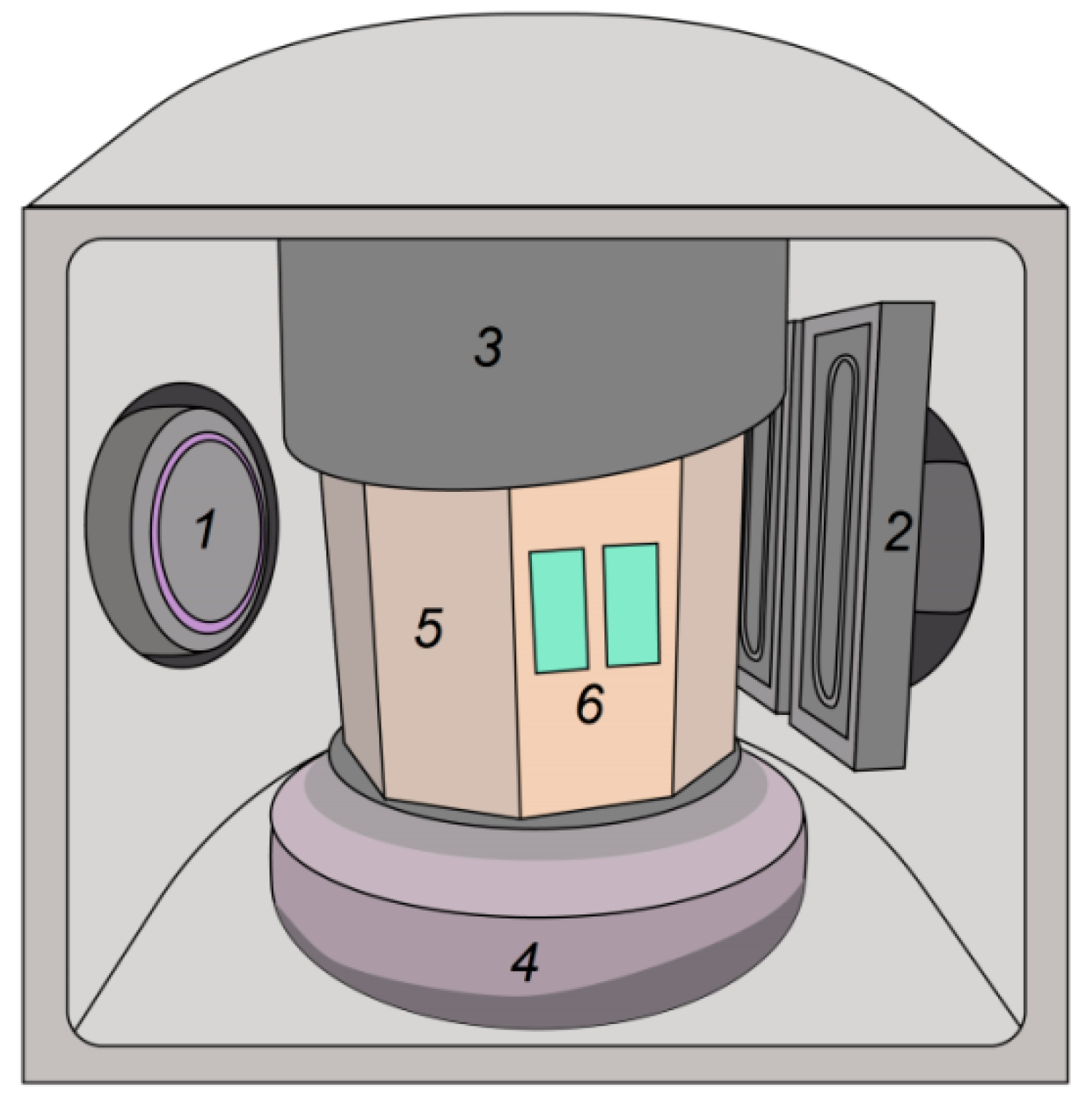
2. Materials and Methods
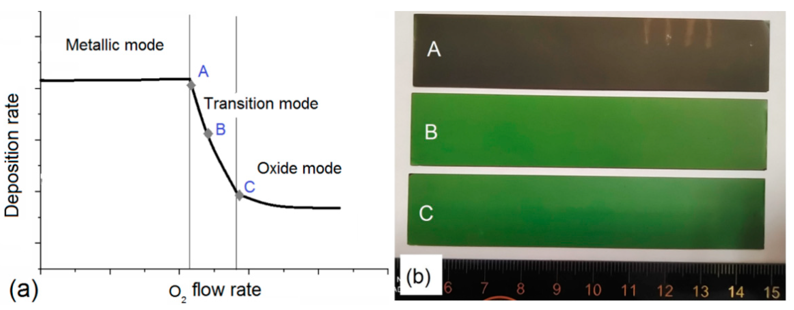
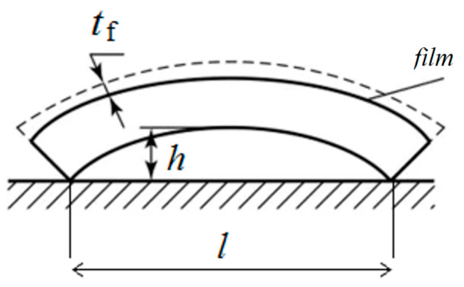
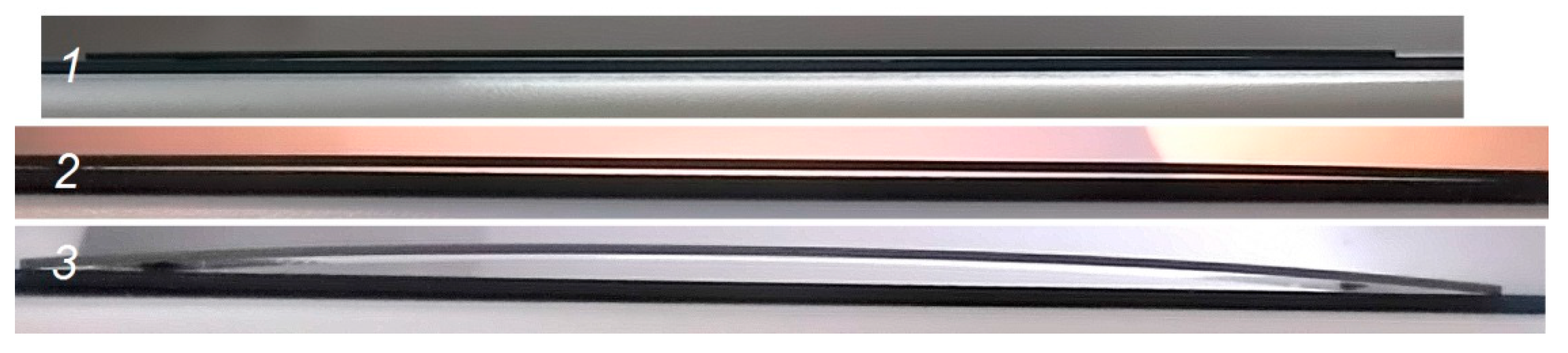
3. Results
4. Conclusions
Author Contributions
Funding
Institutional Review Board Statement
Data Availability Statement
Conflicts of Interest
References
- Blum, L.; de Haart, L.G.J.; Malzbender, J.; Margaritis, N.; Menzler, N.H. Anode-supported solid oxide fuel cell achieves 70,000 hours of continuous operation. Energy Technol. 2016, 4, 939–942. [Google Scholar] [CrossRef]
- Irshad, M.; Siraj, K.; Raza, R.; Rafique, M.; Usman, M.; Ain, Q.; Ghaffar, A. Evaluation of densification effects on the properties of 8 mol.% yttria stabilized zirconia electrolyte synthesized by cost effective coprecipitation route. Ceram. Int. 2021, 47, 2857–2863. [Google Scholar] [CrossRef]
- Kalinina, E.; Shubin, K.; Pikalova, E. Electrophoretic deposition and characterization of the doped BaCeO3 barrier layers on a supporting Ce0.8Sm0.2O1.9 solid-state electrolyte. Membranes 2022, 12, 308. [Google Scholar] [CrossRef]
- Lugovy, M.; Slyunyayev, V.; Steinberger-Wilckens, R. Microcracking in electron beam deposited scandia-stabilised zirconia electrolyte. J. Power Sources 2009, 194, 950–960. [Google Scholar] [CrossRef]
- Montross, C.S.; Yokokawa, H.; Dokiya, M. Thermal stresses in planar solid oxide fuel cells due to thermal expansion differences. Br. Ceram. Trans. 2002, 101, 85–93. [Google Scholar] [CrossRef]
- Faes, A.; Hessler-Wyser, A.; Zryd, A.; Herle, J.V. A review of RedOx cycling of solid oxide fuel cells anode. Membranes 2012, 2, 585–664. [Google Scholar] [CrossRef] [Green Version]
- Yakabe, H.; Baba, Y.; Sakurai, T.; Yoshitaka, Y. Evaluation of the residual stress for anode-supported SOFCs. J. Power Sources 2004, 135, 9–16. [Google Scholar] [CrossRef]
- Atkinson, A. Chemically-induced stresses in gadolinium-doped ceria solid oxide fuel cell electrolytes. Solid State Ion. 1997, 95, 249–258. [Google Scholar] [CrossRef]
- Sun, B.; Rudkin, R.A.; Atkinson, A. Effect of thermal cycling on residual stress and curvature of anode-supported SOFCs. Fuel Cells 2009, 9, 805–813. [Google Scholar] [CrossRef]
- Fischer, W.; Malzbender, J.; Blass, G.; Steinbrech, R.W. Residual stresses in planar solid oxide fuel cells. J. Power Sources 2005, 150, 73–77. [Google Scholar] [CrossRef]
- Malzbender, J.; Fischer, W.; Steinbrech, R.W. Studies of residual stresses in planar solid oxide fuel cells. J. Power Sources 2008, 182, 594–598. [Google Scholar] [CrossRef]
- Sønderby, S.; Christensen, B.H.; Almtoft, K.P.; Nielsen, L.P.; Eklund, P. Industrial-scale high power impulse magnetron sputtering of yttria-stabilized zirconia on porous NiO/YSZ fuel cell anodes. Surf. Coat. Technol. 2015, 281, 150–156. [Google Scholar] [CrossRef] [Green Version]
- Solovyev, A.; Ionov, I.; Lauk, A.; Linnik, S.; Shipilova, A.; Smolyanskiy, E. Fabrication and performance investigation of three-cell SOFC stack based on anode-supported cells with magnetron sputtered electrolyte. J. Electrochem. Energy Convers. Storage 2018, 15, 044501. [Google Scholar] [CrossRef]
- Nédélec, R.; Uhlenbruck, S.; Sebold, D.; Haanappel, V.A.C.; Buchkremer, H.-P.; Stöver, D. Dense yttria-stabilised zirconia electrolyte layers for SOFC by reactive magnetron sputtering. J. Power Sources 2012, 205, 157–163. [Google Scholar] [CrossRef]
- Sønderby, S.; Nielsen, A.J.; Christensen, B.H.; Almtoft, K.P.; Lu, J.; Jensen, J.; Nielsen, L.P.; Eklund, P. Reactive magnetron sputtering of uniform yttria-stabilized zirconia coatings in an industrial setup. Surf. Coat. Technol. 2012, 206, 4126–4131. [Google Scholar] [CrossRef] [Green Version]
- Brahim, C.; Ringuedé, A.; Gourba, E.; Cassir, M.; Billard, A.; Briois, P. Electrical properties of thin bilayered YSZ/GDC SOFC electrolyte elaborated by sputtering. J. Power Sources 2006, 156, 45–49. [Google Scholar] [CrossRef]
- Hong, S.; Lee, D.; Lim, Y.; Bae, J.; Kim, Y.B. Yttria-stabilized zirconia thin films with restrained columnar grains for oxygen ion conducting electrolytes. Ceram. Int. 2016, 42, 16703–16709. [Google Scholar] [CrossRef]
- Coddet, P.; Caillard, A.; Vulliet, J.; Richard, C.; Thomann, A.L. Multistep magnetron sputtering process and in-situ heat treatment to manufacture thick, fully oxidized and well crystallized YSZ films. Surf. Coat. Technol. 2018, 349, 133–143. [Google Scholar] [CrossRef]
- Solovyev, A.A.; Shipilova, A.V.; Rabotkin, S.V.; Ionov, I.V.; Smolyanskiy, E.A. Magnetron deposition of yttria-stabilised zirconia electrolyte for solid oxide fuel cells. Eurasian J. Phys. Funct. Mater. 2018, 2, 206–218. [Google Scholar] [CrossRef] [Green Version]
- Shugurov, A.R.; Panin, A.V. Mechanisms of stress generation in thin films and coatings. Tech. Phys. 2020, 65, 1881–1904. [Google Scholar] [CrossRef]
- Cemin, F.; Abadias, G.; Minea, T.; Lundin, D. Tuning high power impulse magnetron sputtering discharge and substrate bias conditions to reduce the intrinsic stress of TiN thin films. Thin Solid Films 2019, 688, 137335. [Google Scholar] [CrossRef]
- D’Heurle, F.M.; Harper, J.M. Note on the origin of intrinsic stresses in films deposited via evaporation and sputtering. Thin Solid Films 1989, 171, 81–92. [Google Scholar] [CrossRef]
- Windischmann, H. An intrinsic stress scaling law for polycrystalline thin films prepared by ion beam sputtering. J. Appl. Phys. 1987, 62, 1800–1807. [Google Scholar] [CrossRef]
- Stenzel, O.; Wilbrandt, S.; Kaiser, N.; Vinnichenko, M.; Munnik, F.; Kolitsch, A.; Chuvilin, A.; Kaiser, U.; Ebert, J.; Jakobs, S. The correlation between mechanical stress, thermal shift and refractive index in HfO2, Nb2O5, Ta2O5 and SiO2 layers and its relation to the layer porosity. Thin Solid Films 2009, 517, 6058–6068. [Google Scholar] [CrossRef]
- Bae, J.; Chang, I.; Kang, S.; Hong, S.; Cha, S.W.; Kim, Y.B. Post-annealing of thin-film yttria stabilized zirconia electrolytes for anode-supported low-temperature solid oxide fuel cells. J. Nanosci. Nanotechnol. 2014, 14, 9294–9299. [Google Scholar] [CrossRef] [PubMed]
- Briois, P.; Gourba, E.; Billard, A.; Ringuedé, A.; Cassir, M. Microstructure—Electrical properties relationship of YSZ thin films reactively sputter-deposited at different pressures. Ionics 2005, 11, 301–305. [Google Scholar] [CrossRef]
- Paek, J.Y.; Chang, I.; Park, J.H.; Ji, S.; Cha, S.W. A study on properties of yttrium-stabilized zirconia thin films fabricated by different deposition techniques. Renew. Energy 2014, 65, 202–206. [Google Scholar] [CrossRef]
- Musil, J.; Baroch, P.; Vlček, J.; Nam, K.H.; Han, J.G. Reactive magnetron sputtering of thin films: Present status and trends. Thin Solid Films 2005, 475, 208–218. [Google Scholar] [CrossRef]
- Berg, S.; Nyberg, T.; Kubart, T. Modelling of Reactive Sputtering Processes. In Reactive Sputter Deposition; Depla, D., Mahieu, S., Eds.; Springer: Berlin/Heidelberg, Germany, 2008; pp. 131–152. [Google Scholar]
- Spencer, A.G.; Howson, R.P. System Design for High Rate Deposition of Indium Oxide Solar Coatings. In Optical Materials Technology for Energy Efficiency and Solar Energy Conversion VII, Proceedings of the SPIE, Hamburg, Germany, 19–23 September 1988; International Society for Optics and Photonics: Bellingham, WA, USA, 1989; p. 1016. [Google Scholar] [CrossRef]
- Okamoto, A.; Serikawa, T. Reactive sputtering characteristics of silicon in an Ar-N2 mixture. Thin Solid Films 1986, 137, 143–151. [Google Scholar] [CrossRef]
- Kelly, P.J.; West, G.; Kok, Y.N.; Bradley, J.W.; Swindells, I.; Clarke, G.C.B. A comparison of the characteristics of planar and cylindrical magnetrons operating in pulsed DC and AC modes. Surf. Coat. Technol. 2007, 202, 952–956. [Google Scholar] [CrossRef]
- Nyberg, T.; Berg, S.; Helmersson, U.; Hartig, K. Eliminating the hysteresis effect for reactive sputtering processes. Appl. Phys. Lett. 2005, 86, 164106. [Google Scholar] [CrossRef]
- Coddet, P.; Pera, M.C.; Billard, A. Reactive co-sputter deposition of YSZ coatings using plasma emission monitoring. Surf. Coat. Technol. 2011, 205, 3987–3991. [Google Scholar] [CrossRef]
- Fernandes, S.L.; Albano, L.G.S.; Affonço, L.J.; Silva, J.H.D.; da Longo, E.; de Oliveira Graeff, C.F. Exploring the properties of niobium oxide films for electron transport layers in perovskite solar cells. Front. Chem. 2019, 7, 50. [Google Scholar] [CrossRef] [PubMed]
- Janssen, G.; Abdalla, M.M.; van Keulen, F.; Pujada, B.R.; van Venrooye, B. Celebrating the 100th anniversary of the Stoney equation for film stress: Developments from polycrystalline steel strips to single crystal silicon wafers. Thin Solid Films 2009, 517, 1858–1867. [Google Scholar] [CrossRef]
- Pihlatie, M.; Kaiser, A.; Mogensen, M. Mechanical properties of NiO/Ni–YSZ composites depending on temperature, porosity and redox cycling. J. Eur. Ceram. Soc. 2009, 29, 1657–1664. [Google Scholar] [CrossRef]
- Giraud, S.; Canel, J. Young’s modulus of some SOFCs materials as a function of temperature. J. Eur. Ceram. Soc. 2008, 28, 77–83. [Google Scholar] [CrossRef]
- Tang, C.J.; Jaing, C.C.; Lee, K.S.; Lee, C.C. Residual stress in Ta2O5-SiO2 composite thin-film rugate filters prepared by radio frequency ion-beam sputtering. Appl. Opt. 2008, 47, 167–171. [Google Scholar] [CrossRef]
- Quinn, D.J.; Wardle, B.; Spearing, S.M. Residual stress and microstructure of as-deposited and annealed, sputtered yttria-stabilized zirconia thin films. J. Mater. Res. 2008, 23, 609–618. [Google Scholar] [CrossRef]
- Götsch, T.; Wallisch, W.; Stöger-Pollach, M.; Klötzer, B.; Penner, S. From zirconia to yttria: Sampling the YSZ phase diagram using sputter-deposited thin films. AIP Adv. 2016, 6, 025119. [Google Scholar] [CrossRef] [Green Version]
- Thornton, J. High-rate thick- film growth. Annu. Rev. Mater. Sci. 1977, 7, 239–260. [Google Scholar] [CrossRef]
- Sochugov, N.S.; Soloviev, A.A.; Shipilova, A.V.; Rabotkin, S.V.; Rotshtein, V.P.; Sigfusson, I.T. The effect of pulsed electron beam pretreatment of magnetron sputtered ZrO2:Y2O3 films on the performance of IT-SOFC. Solid State Ion. 2013, 231, 11–17. [Google Scholar] [CrossRef]
- Paz Alpuche, E.; Gröger, P.; Wang, X.; Kroyer, T.; Fasoulas, S. Influence of the sputtering technique and thermal annealing on YSZ thin films for oxygen sensing applications. Coatings 2021, 11, 1165. [Google Scholar] [CrossRef]
- Atkinson, A.; Selçuk, A. Residual stress and fracture of laminated ceramic membranes. Acta Mater. 1999, 47, 867–874. [Google Scholar] [CrossRef]
- Jia, L.; Lu, Z.; Miao, J.; Liu, Z.; Li, G.; Su, W. Effects of pre-calcined YSZ powders at different temperatures on Ni–YSZ anodes for SOFC. J. Alloys Compd. 2006, 414, 152–157. [Google Scholar] [CrossRef]
- Kim, E.; Kim, H.; Bae, C.; Lee, D.; Moon, J.; Kim, J.; Shin, H. Formation of yttria-stabilized zirconia nanotubes by atomic layer deposition toward efficient solid electrolytes. Nano Converg. 2017, 4, 31. [Google Scholar] [CrossRef] [Green Version]


| YSZ Electrolyte Films | Deposition Modes | Pressure, Pa | Deposition Rate, nm/min | Film Thickness, µm | Residual Stress, MPa | |
|---|---|---|---|---|---|---|
| After Deposition | After 1200 °C Annealing | |||||
| 1 | Oxide | 0.4 | 6.1 | 4 | 1780 | 947 |
| 2 | Transition | 0.4 | 16 | 4 | 690 | 166 |
| 3 | Transition | 0.4 | 45 | 5 | 670 | 6631 |
| 4 | Transition | 0.2 | 25 | 6.1 | 455 | 6336 |
| 5 | Transition | 0.2 | 25 | 6.1 | 505 | 1764 1 |
| 6 | Transition | 0.2 | 35 | 4.7 | 930 | 371 1 |
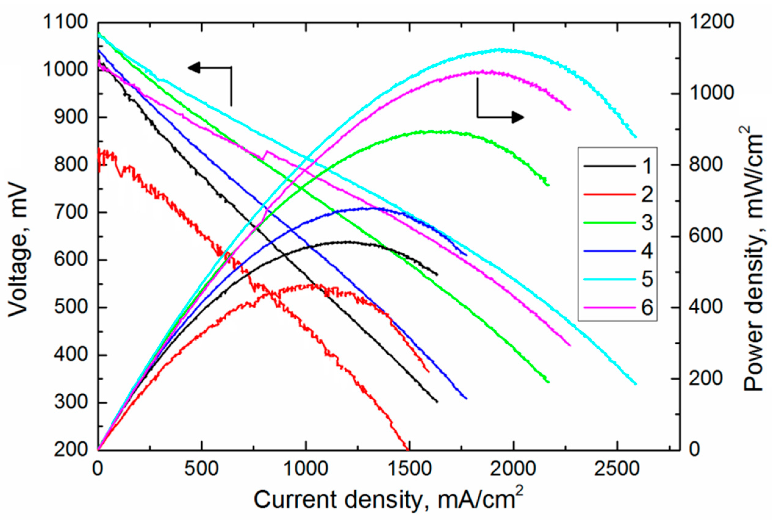
| SOFCs | Open Circuit Voltage, mV | Maximum Power Density, mW/cm2 |
|---|---|---|
| 1 | 1043 | 586 |
| 2 | 816 | 462 |
| 3 | 1083 | 896 |
| 4 | 1051 | 678 |
| 5 | 1082 | 1225 |
| 6 | 1057 | 1063 |
Publisher’s Note: MDPI stays neutral with regard to jurisdictional claims in published maps and institutional affiliations. |
© 2022 by the authors. Licensee MDPI, Basel, Switzerland. This article is an open access article distributed under the terms and conditions of the Creative Commons Attribution (CC BY) license (https://creativecommons.org/licenses/by/4.0/).
Share and Cite
Solovyev, A.; Rabotkin, S.; Shipilova, A.; Agarkov, D.; Burmistrov, I.; Shmakov, A. Influence of Deposition Modes and Thermal Annealing on Residual Stresses in Magnetron-Sputtered YSZ Membranes. Membranes 2022, 12, 346. https://doi.org/10.3390/membranes12030346
Solovyev A, Rabotkin S, Shipilova A, Agarkov D, Burmistrov I, Shmakov A. Influence of Deposition Modes and Thermal Annealing on Residual Stresses in Magnetron-Sputtered YSZ Membranes. Membranes. 2022; 12(3):346. https://doi.org/10.3390/membranes12030346
Chicago/Turabian StyleSolovyev, Andrey, Sergey Rabotkin, Anna Shipilova, Dmitrii Agarkov, Ilya Burmistrov, and Alexander Shmakov. 2022. "Influence of Deposition Modes and Thermal Annealing on Residual Stresses in Magnetron-Sputtered YSZ Membranes" Membranes 12, no. 3: 346. https://doi.org/10.3390/membranes12030346