
Multiagent Control of Airplane Wing Stability with “Feathers” under the Flexural Torsional Flutter


1
Department of Mathematics and Computer Science, St. Petersburg State University, Universitetskaya nab. 7-9, 199034 Saint Petersburg, Russia
2
Mathematics and Mechanics Faculty, St. Petersburg State University, Universitetskaya nab. 7-9, 199034 Saint Petersburg, Russia
3
Science Research and Educational Center “Mathematical Robotics and Artificial Intelligence”, St. Petersburg State University, Universitetskaya nab. 7-9, 199034 Saint Petersburg, Russia
4
Laboratory “Control of Complex Systems”, Institute for Problems in Mechanical Engineering of Russian Academy of Sciences, V.O. Bolshoj pr. 61, 199178 Saint Petersburg, Russia
5
Faculty of Economics, St. Petersburg State University, Universitetskaya nab. 7-9, 199034 Saint Petersburg, Russia
6
Software Engineering Department, Ort Braude College, Ort Braude College, Rehov Snunit 51, POB 78, Karmiel 2161002, Israel
*
Author to whom correspondence should be addressed.
†
These authors contributed equally to this work.
Mathematics 2022, 10(2), 236; https://doi.org/10.3390/math10020236
Submission received: 2 December 2021
/
Revised: 9 January 2022
/
Accepted: 10 January 2022
/
Published: 13 January 2022
(This article belongs to the Section Mathematics and Computer Science)
Abstract
:This paper proposes a novel method for the unbounded oscillation prevention of an aircraft wing under the flexural torsional flutter, an innovative multiagent attitude to control an aircraft wing with a surface consisting of managed rotating “feathers” (agents). Theoretical evaluation of the method demonstrates its high aptitude to avoid an aircraft wing’s flexural-torsional vibrations via expansion of the model’s ability to dampen the wing oscillations. It potentially allows increasing an aircraft’s speed without misgiving of the flutter. A new way to control an aircraft wing based on the Speed-Gradient methodology is suggested to increase the maximal possible flight speed without a flutter occurrence. Provided experiments demonstrate the theoretical advantage of the multiagent approach to the “feathers” rotation control.
1. Introduction
The paper investigates a critical problem of airplane wing control under the flexural torsional flutter. Availability of a stable solution leads to the aptitude to maintain wing integrity under oscillations during a flight and prevents significant component strain. After attaining a certain flight speed, say , oscillations of the wing rapidly and catastrophically increase until the wing breaks if the oscillations continue. This event is, so named, the flutter phenomenon. Even in horizontal flight at a constant speed on a heavy transport aircraft, the deflection of the wing can achieve several meters [1] so that the corresponding deformations affect the magnitude and distribution of the aerodynamic load leading potentially to structural instability, both static (wing divergence) and dynamic (flutter).
As a result, safeguarding the required aerodynamic characteristics and wing stability in various aircraft flight phases is needed. It should be noted that the elements of the appropriate automation are widespread in modern aircraft construction (pre-flaps, ailerons, flaps, etc.) serving precisely this purpose, in particular, in the most vital take-off and landing modes. However, there is no standard way to counteract wing flutter effectively except an opportunity to impose a limit on the aircraft’s maximum flight speed to be less than .
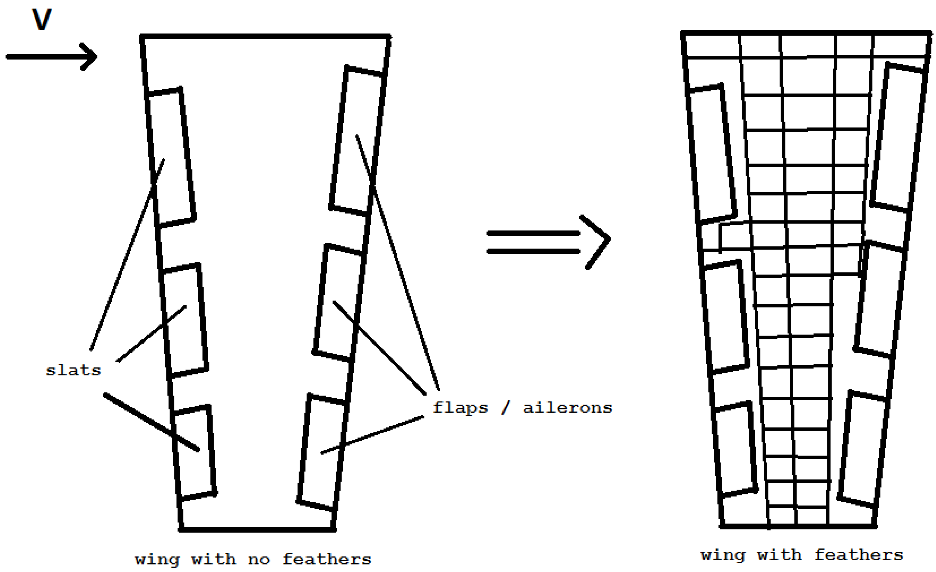
A novel approach proposed in this paper suggests covering an aircraft wing both above and below with small-sized rotating elements (“feathers”) capable of changing the orientation according to the airflow. In the neutral position, when “feathers” are not raised but lie on the surface, they do not affect the calculated wing profile (see Figure 1, the left panel). In this case the wing dynamic does not deteriorate.
The proposed methodology’s novelty lies in using “feathers” on the aircraft’s surface. We consider the set of these “feathers” as a multiagent system. At the heart of multiagent systems is a decentralized approach. Dynamically updated information flow within a distributed network is processed, not centrally, but directly at the agents based on their local observations and locally available data from the appropriate neighbors. Simultaneously, both resource and time costs of communication are significantly lessened, and the processing and decision-making time in the center (if it does exist). Such an approach is new and has not been considered before in the flutter problem area.
Because of the relatively intensive wing oscillations during a flutter, its essential performance indicator is embodied by a period needed to damp and maintain vibrations safely. Each “feather” tries to minimize the deviation of a wing segment to which it is initially attached. This action, in general, is not consolidated with other “feathers”. However, the interaction of all “feathers” creates a new ability as a multiagent system to reduce the vibrations. It produces a kind of emergent intelligence (intellectual resonance, swarm intelligence) or an appearance of unexpected system properties not inherent to the individual elements.
In the paper, we suppose a mathematical model of the bending-torsional vibrations of an airplane wing with controlled “feathers” on its surface and consider three functionally different statements of the control problem. Additionally, three control laws are synthesized by the Speed-Gradient method. We illustrate the advantage of the multiagent approach by a simulation example. A crucial theoretical suggestion is the capability of a “feather” to swap the orientation instantly along with the airflow. The effect of a possible delay is a subject of further research.
The rest of the paper is structured in the following way: Section 2 provides an overview of related works. Section 3 is devoted to studying system dynamics under small flexural-torsional vibrations. In Section 4 it is shown how the Speed-Gradient method can be used to synthesize the control law. Section 5 describes the multiagent control laws produced using the Speed-Gradient method given in Section 4. Simulation results are provided in Section 6, and Section 7 is devoted to the conclusion.
2. Related Work
The condition frontier between stable and self-sustaining motions in a flight is named flutter speed and flutter boundary [2]. The flutter can be divided into several groups according to the instability appearing with changes in conditions. An explosive flutter occurs due to exceeding the flutter speed . This process results in highly divergent oscillations, and the airplane can break within a fraction of a second. Earlier it was believed that the flutter problem could be solved during flight testing. Nevertheless, since February 1938 when a four-engined Junkers plane Ju 90 VI crashed during a carefully planned flight, it has been acknowledged that the flutter characteristics should be investigated before the flight tests [3].
The moderate (mild) flutter corresponds to the case when the system is stable and the occurring oscillations can be identified and damped well below the flutter speed by extrapolating the instabilities.
An approach intended to steady an unstable flutter system is called Active Flutter Suppression (AFS). A broad overview of AFS research is presented in [4]. The study of the ability to suppress flutter instability through actively controlled closed-loop action of control surfaces has a long history [5]. Numerous studies in this field were carried out as early as the 1970s and 1980s [6]. Various approaches to synthesizing AFS systems’ control law, including adaptive control methods and control with variable parameters, are also considered [7,8,9,10]. AFS is essential for an effective solution of aeroelastic instability problems and can lead to significant aircraft and airframe weight savings (see, [11]).
The AFS approach based on the elimination of delays in loading growth induced by unsteady aerodynamic stresses is investigated in [12]. The concepts of “active flexible wing” or “active flexible airframe” are regarded in [13]; during flight stability and controllability of rigid and flexible aircraft are considered in [14,15,16]. The influence of the aeroelasticity on stability and controllability of flight using corrections of the derivatives of static aeroelastic stability is studied in [17]; an active controls perspective is presented in [18].
The idea of using an active control system has been considered and discussed since the advent of flights with a human crew [14,15]. The adaptive control methodology appears attractive due to multiple plant characteristics and the ability to respond to damage scenarios, refs. [19,20,21,22,23,24]—article [25] attempts to systematize the modern control theory laws developed in the field. A comprehensive review of methods for synthesizing control laws and modeling of aeroelastic systems is presented in [26]. In this respect, it is possible to recall several works considering different aspects of the mentioned thematics [8,9,10,27,28,29,30,31].
Multiagent systems have many applications in civilian, security, and military areas [32,33]. A centralized approach to quantitative and qualitative modeling, analysis, constraint satisfaction, maintenance, and control seem to be too strict for these systems [34]. On the other hand, the distributed and incremental reasoning seems to be more scalable, robust and flexible. It is one of the reasons why an investigation of multiagent control systems is popular [35,36,37]. The multiagent methodology can serve the general model of the interactions in a complex system [37,38,39]. An overview of publications considering the emergent intelligence and self-organization in groups of devices is provided in [34].
The idea to use a set of “feathers” on the wing of an airplane is put forward in [40,41,42] where the group of “feathers” is considered as a dynamic network. A multiagent protocol for their control is investigated and is used to level the perturbing forces in the turbulence. External disturbances form cluster structures among “feathers” on the wing of an airplane due to the multiagent control protocol. Control problems for airplanes with corresponding clusters are studied in [43]. The general problem of cluster flow control is considered in [44,45].
3. Dynamics Equations of Wing with “Feathers”
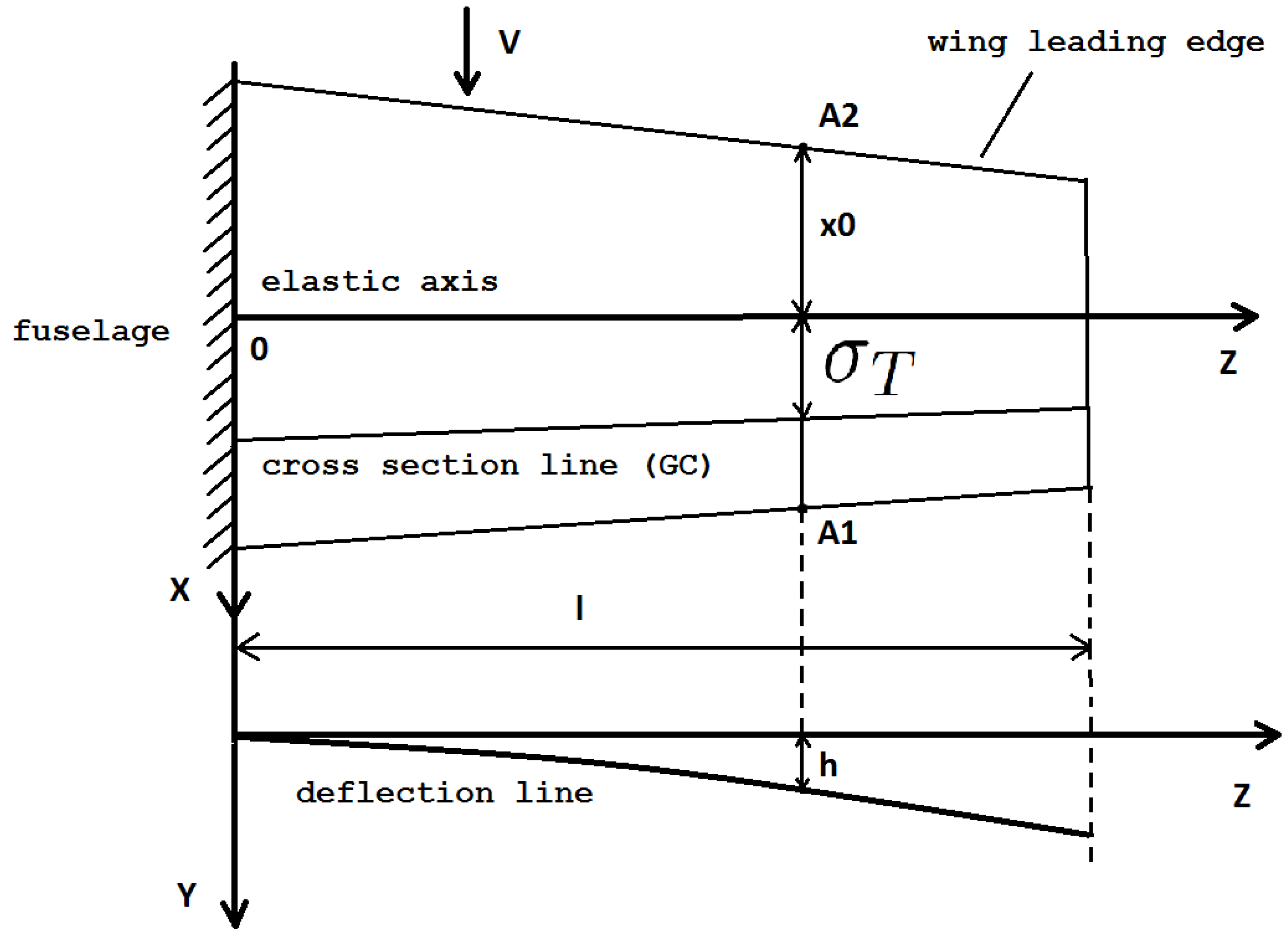
This section describes the proposed “wing with feathers” approach. Let us consider the flexural-torsional flutter phenomenon described in [3,46] in a steady horizontal flight at a constant speed. We regard the non-sweeping wing of the half-span l and “feathers” in neutral position as a cantilevered beam with a static distributed load on bending and torsion. The elastic axis of the wing passes through the Stiffness Centers (SC’s) of the sections and does not coincide with the line of the sections’ Gravity Centers (GC’s). (Otherwise, when SC’s and GS’s coincide, we face a “degenerate case” of either bending or torsion of the wing [3,46].) We assume that the wing stiffness in the longitudinal and transverse directions of the wing plane is very large and consequently neglect the vibrations in these directions. We also ignore the possible movements of the SC and GC along the sections during the flight. Figure 2 illustrates the conceivable location of the SC and GC lines on a wing.
Note that typically the GC is located behind the SC section.
The corresponding equations of the elastic line of the beam are of the form [5]:
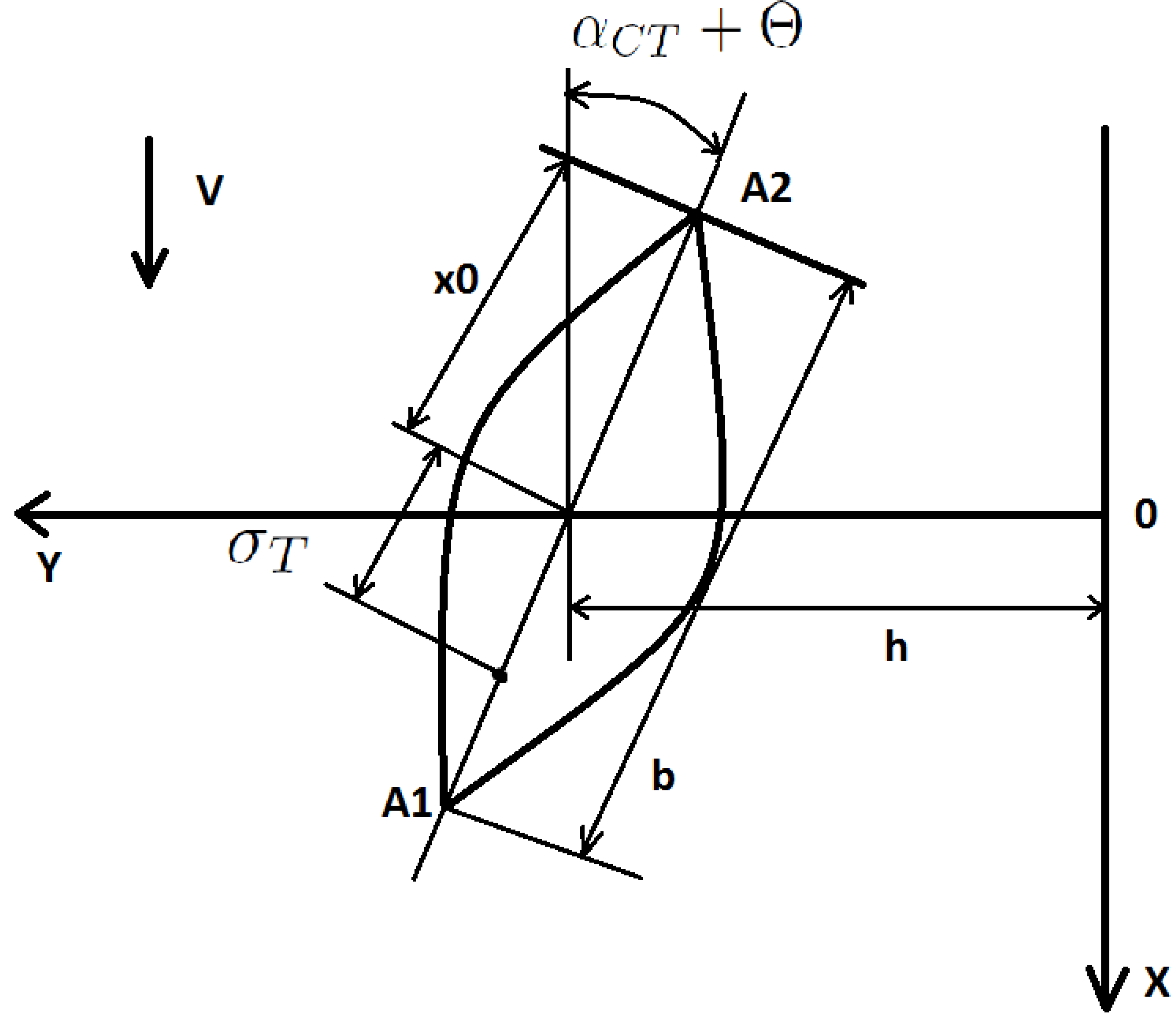
where as presented in Figure 3
- b is the wing section chord;
- h is the transverse deflection of the section ;
- is the angle of attack in the section of the undeformed wing;
- is the wing twist angle, which is considered positive if it increases the angle of attack in the section;
- are the wing stiffness in bending and torsion, respectively;
- and are the linear force and moment relative to the stiffness axis acting on the wing.
The functions of (1) are time-independent since the wing is in a steady (stationary) state:
The solutions should have form
where and are vibration mode functions, and must satisfy the boundary conditions at the ends of the wing [3]
Now, suppose that for some unknown reason like sudden aileron movement, air holes, a gust of wind, and so on, the wing deviated from its stationary position (2). At the end of the specified impact, after the cessation of this factor exposure, the wing returns to the equilibrium state under the influence of the elastic forces. If the energy dissipation is insignificant, the aperiodic process does not appear. However, wing oscillations may arise. We assume that these fluctuations could be initially ignored and do not affect the aircraft dynamics. According to [3,46], small bending-torsional oscillations of a wing near its equilibrium position (2) and (3) in the laminar flow are described by the following equations:
where
- m is the linear mass of the wing;
- is the linear mass moment of inertia of the wing relative to its stiffness axis;
- and are the linear aerodynamic force of the wing and the linear moment of the aerodynamic force relative to the stiffness axis, due to wing vibrations.
Solutions of the system (4) must satisfy boundary conditions similar to (3). We represent the right-hand sides of (4) in the form:
where
- and are the linear aerodynamic force and moment relative to the stiffness axis respectively, arising due to wing oscillations in the neutral position of the “feathers”;
- and are the linear aerodynamic force and moment created by changing the orientation of the “feathers”.
Following the flutter equations ([46], p. 176, Equation (35)) and taking into account linear aerodynamic forces and moment and , we rewrite (4) as
where
- ; is the wing lift coefficient;
- is considered constant along the span;
- is the instant value of the angle of attack when the wing moves;
- is the value of the angle of attack at which ;
- is the air density.
The first equation in (5) stands for the value of the linear aerodynamic force affecting the wing in case of its significant deviation from the equilibrium position. It includes two parts, such that the first is obtained by substitution of aerodynamic force affecting the wing in equilibrium position from (4), and the second one denotes the effect of the airflow on the wing arising due to its deviation from the equilibrium position. The second equation in (5) is obtained similarly to the first one and stands for the value of the moment created due to the wing deviation from the equilibrium position. The third and the fourth equation exhibit the boundary conditions.
As can be seen from (5), the bending and torsional vibrations of the wing are interdependent. It is one of the necessary conditions for flutter occurrence. It appears also that with increasing speed V, the bending and torsional oscillations approach each other, and for they coalesce [5]. Moreover, there is a phase shift between these oscillations, a necessary condition for the occurrence of flutter [3,46].
It is important to remark that in this case the amplitude oscillations wavers around a small constant value. So the oscillations themselves are no longer self-damped, as it was the case where . The crucial problem arises when , i.e. when the slightest deformations overgrow catastrophically.
In terms of (5), it is necessary to form and to prevent flutter so that a wing oscillation energy is bounded. The bound value is reliable from a controllability standpoint, taking into account the aircraft structure’s stability and integrity. So, if , for the total energy of the cantilevered beam [46], the condition is:
A stricter requirement is to get the system (5) solution in a given small neighborhood of the solution of (2):
where
The force and the moment impacts are influenced by the high-speed pressure and therefore should depend on the velocity of the flow of V, the position of the “feathers” on the wing, their orientation and other factors associated with the adopted aerodynamic calculation scheme.
Let us assume that the “feathers” are entirely rigid structural elements and that a change in the “feather’s” orientation does not affect the airflow around the remaining “feathers”. We also suppose that a wing as a whole keeps its laminarity. Then:
where and are the additional linear force and the moment from the i-th “feather” correspondingly. The summation is carried out over all “feathers”, covering the section frontier.
The rotation angle between the “feathers” on the upper surface and the wing profile and between the “feathers” on the lower surface and the wing profile are usually represented by their tangent values.
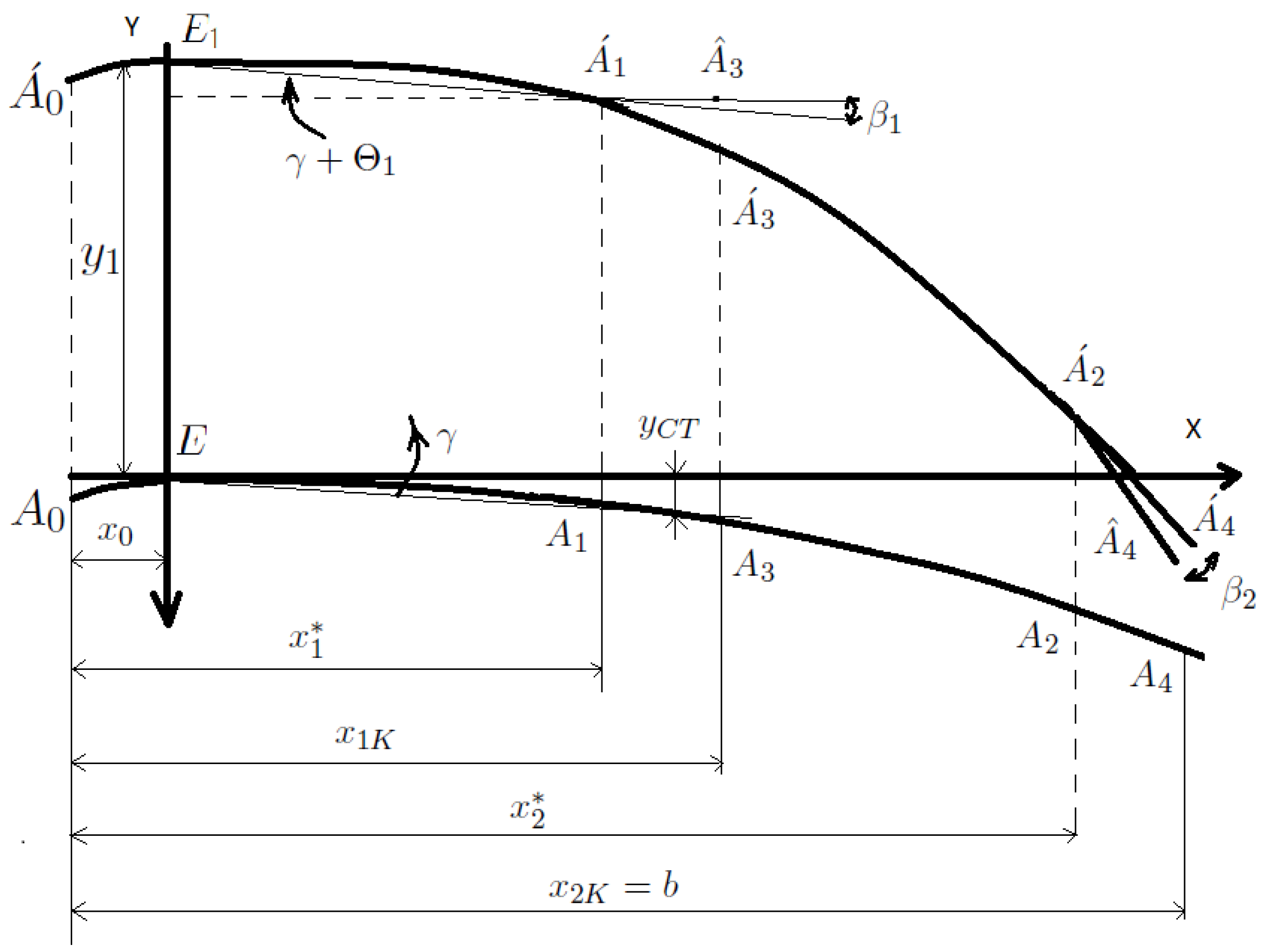
In Figure 4:
- E and are SC’s of the wing section in the static position and during vibrations, respectively; and is the deflection of the wing;
- X-axis corresponds to the main stream speed;
- Y-axis is perpendicular to X-axis and to the axis of rigidity of the undeformed wing;
- are wing profiles (considered to be sufficiently thin) in a static position (before vibrations);
- are wing profiles during oscillations;
- are the front and back edges of the “feather” 1 in the neutral position on the corresponding profiles;
- are the front and back edges of the “feather” 2 (analog of the aileron) in the neutral position on relevant profiles;
- and are the trailing edges of the “feathers” 1 and 2, respectively, after their deviations.
- and are the distances from the leading and trailing edges of the “feather” 1 to the leading edge of the wing;
- and are similar parameters for the “feather” 2;
- is the angle of twisting of the wing near the point ;
- is the angle of deviation of the “feather” 1 from the neutral position;
- is the angle of deviation of the “feather” 2 from the neutral position;
Parameters , wing deflection are ordinates in a static position, are considered small.
Following the technique suggested by ([46], pp.143–146), it can be shown that the influence of the i-th “feather” on the wing is generally calculated as:
where
According to [3,46], the solution of (5) near the flutter is
where and are vibration modes functions, satisfying the boundary conditions: at at
Here for the sake of simplicity, we suggest that ,
Substituting (10) into (5), multiply the first equation by f and the second by and then integrate from 0 to l, we obtain after several simple transformations taking into account (8) and (9):
where
N is the total “feathers” number.
Given the functions, f and and the distributions of the mass and stiffness parameters of the wing (we consider them to be time-independent), the coefficients and can be figured out to be constants. The further results hardly rest on the choice of the functions f and . Note without going into details that these functions can be reasonably calculated, for example, by the successive approximations method. We complete (11) with the control equations
where is the total number of “feathers” on the lower surface of the wing;
is total number of “feathers” on the upper surface of the wing.
Introduce:
Then, we substitute (13) into (11) and reduce this system to the normal Cauchy form. After combining (11) and (12), we get
where
Finally, by integration by parts, we get:
Thus dynamics of the system (14) describes small flexural-twisting wing oscillations in a laminar flow taking into account the linear aerodynamic force and moment together with the Equation (15) of limiting the total system energy. The changing rate of the inclination angle of the “feather” concerning the wing plane can be considered as a control parameter.
4. Control Synthesis with the Speed-Gradient Method
To equalize the impact of the forces on different parts of the wing, we use the Speed-Gradient Principle [47,48] aiming to derive the “feather” angle control law. According to this principle, all physical systems evolve along the shortest path in the direction of thermodynamic equilibrium appearing with the maximal entropy value. In the Speed-Gradient algorithm, the maximal increment of entropy corresponds to the minimal value of the energy in (15).
Up to this point, we have described the dynamic system taking into account what the solution in the optimal state determined by (15) should look like. However, a control law admitting the system to reach the desired state is absent. In this section such a law is produced.
First of all, we seek to control for the (14) with the criterion of (15), using the speed-gradient method introduced in [47,48].
where
Thus,
or
Since for all values of and it means that ,
The resulting control equation derived following the Speed-Gradient Principle
is a control in the form of feedback on a deviation with constant coefficients.
5. Multiagent Control
Application of the multiagent control leads to the arising of an emergent intelligence (intellectual resonance, swarm intelligence) expressed in unexpected system properties not inherent to its individual elements. In our connotation, each “feather” aims to solve its own “task” of minimizing the deviation of the source wing segment to which it is initially attached. The “feather’s” performance, in general, is not consolidated. However, a combination of all feathers’ impacts causes a new wing property to be a multiagent system of feathers to dampen the vibrations.
Hence, let us consider the feathers as intelligent agents. So each of them can receive information about the movement of the wing, exchange this information with other agents (transfer its information to them and receive their information), process the received data, and form local force and moment impacts, trying to keep the wing as close to its initial shape as possible. Assuming the “feather’s” size is relatively small compared to the wing’s surface, we relate a “feather” to some point on the wing’s surface in the neutral position.
Introduce for each “feather” ():
- are coordinates of the point to which the i-th “feather” is attached;
- and are deflection and angle of twisting of the wing at the location of the i-th “feather” (deviations from the curve (2));
- is the subset of “feathers” exchanging information with the i-th “feather”;
- is a non-negative weighting coefficient denoting the significance of information passing from the i-th “feather” to the j-th. Here, we assume that and ; here if the i-th and j-th “feathers” are not connected;
- is the adjacency matrix of the network.
Moreover, we take into account that
The compensation for deviations from the stationary position is given as
The problem by analogy with [41] is formulated as follows. In conditions of a uniform rectilinear flight of the aircraft in a laminar flow approaching the critical speed of flexural-torsional flutter onset , it is required to find such controls for each “feather” in the system (14), that would ensure the fulfillment of the target condition for the functional (18):
for a small given tolerance for during a sufficiently long period. The “feather” control laws are generated according to the Speed-Gradient Principle as discussed above. A similar approach has also been applied in the study of nonlinear dynamics [49].
5.1. Non-Multiagent Control Synthesis
Let us consider the functional
We suppose that which implies
where , , , is defined in (17), and
So:
where and are constants determined by the topology of the agent network (a wing in our model for given functions of the waveforms and ). A singular situation appears once or .
Consequently:
since the integration constant is zero for the same reasons as in (16).
Equations (16) and (20) have the same overall structure with some differences. In fact, according to (14), we can consider the coefficients and as the coefficients of influence of the i-th “feather” on the force factor in the bending vibrations and on the moment factor in torsional vibrations, respectively. Actually, the values of these coefficients exhibit the participation degree of the i-th “feather” in wing dynamics.
In (16) the feedback coefficients take into account the influence of the types of a wing oscillations on each other, while in (20) the feedback coefficients for bending and torsional vibrations are strictly separated and determined through influence factors only on own oscillation type. The Equation (20) is not multiagent by its nature since its dependence upon information about the state of other agents is static and its dependence upon information about the state of other agents, and it is invariant to the dynamics of the i-th “feather”.
5.2. Multiagent Control Synthesis
Now, let us return to (14). We expand the vector of phase coordinates by introducing
For this extended vector, we compose a functional analogously to (19) a functional
The application of the proposed approach can be justified as that for minor deviations of a wing from the stationary position, determined by (2), deviations of the “feathers” from their neutral position should be small as well. The following is correct, at least for the “feathers” lying on one side of a wing (lower/upper)
where is a reasonably small number.
After simple transformations, we get
Now, we apply the Speed-Gradient method:
Finally, the control law is:
It is essential to pay attention to the multiagent nature of the control protocol of (21) and (24), since the control signal for the rotation of each “feather” is formed based on information about its own current state and the current state of the “feathers” connected with it. The connection is defined by the second term in (24) which states the dependence of i-th “feather” angle adjustment on the deviation of “feather” angle from its neighbors’ angles , . At the same time, the first part of (24) describes a control in the form of feedback with constant coefficients according to the speed of deviation of bending and torsional vibrations from the stationary state (2).
It is essential that does not entail since in the general case there can be and To reduce them, it is necessary to apply a control defined by (24). The expression is true only in the case of complete absence of oscillations, when since only then
The control (24) does not explicitly depend on the time instant, at which the critical flutter speed is reached, allowing this control without any changes at different speed values. Also, introduced control for each “feather” i uses only local information: its own angle and angles of its nearest neighbors , . On the one hand, the suggested procedure does not require data collection from all “feathers” on the wing to form the controls (24) since it is only required for each agent to pass the value of its angle to its nearest neighbors. On the other hand, according to the formula (24) just local information is enough to compute the control inputs. Such a “low cost” information demand is an essential feature of the multiagent approach, making it beneficial for application in large network systems.
6. Simulation
Let us compare performance of the multiagent system of “feathers” under control of the introduced control laws: synthesized with the speed-gradient method (16), non-multiagent (21) and multiagent (24) control laws. In the simulation experiments the constants are chosen as:
- time step ;
- number of time instants ;
- airspeed ;
- air density .
The parameters of the aircraft wing have the following values:
- linear mass of the wing ;
- wing section chord ;
- wing (half-span) length ;
- from (5) the derivative of the wing lift coefficient with respect to , ;
- wing stiffness in bending ;
- wing stiffness in torsion ;
- distance between stiffness centers and gravity centers in the wing cross section assumed to be constant and equal ;
- wing cross-section is assumed to be elliptical with height ;
- linear mass moment of inertia of the wing relative to its stiffness axis
The “feathers” are configurated as follows:
- number of “feathers” ;
- “feather” coordinates in Z axis ;
- “feather” coordinates in X axis according to formulas (9) ;
- the coordinates of “feathers” trailing edges in X axis equal ;
- the coordinates of “feathers” joint in X axis ;
- the distance from the leading edge of the wing to the SC section .
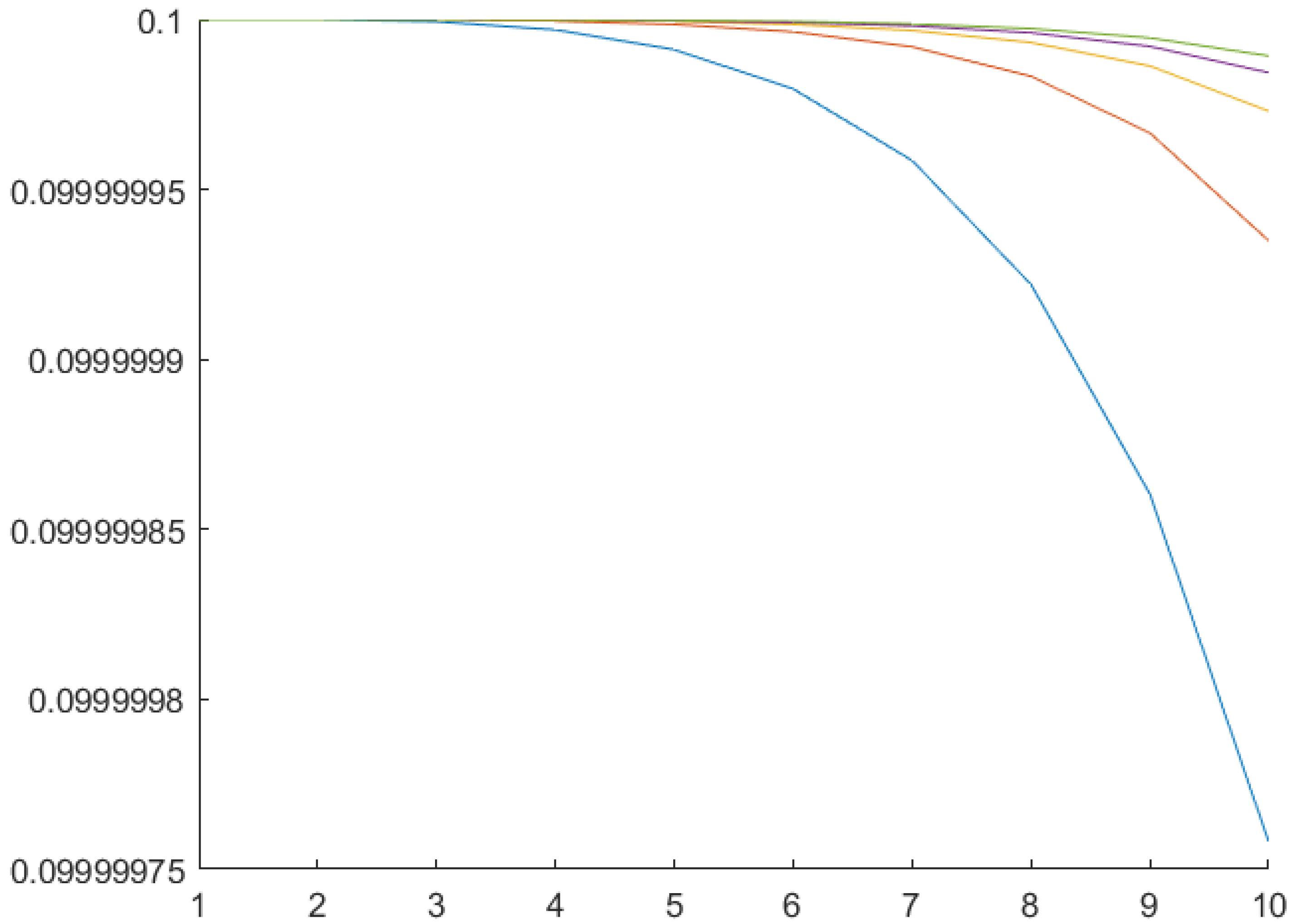
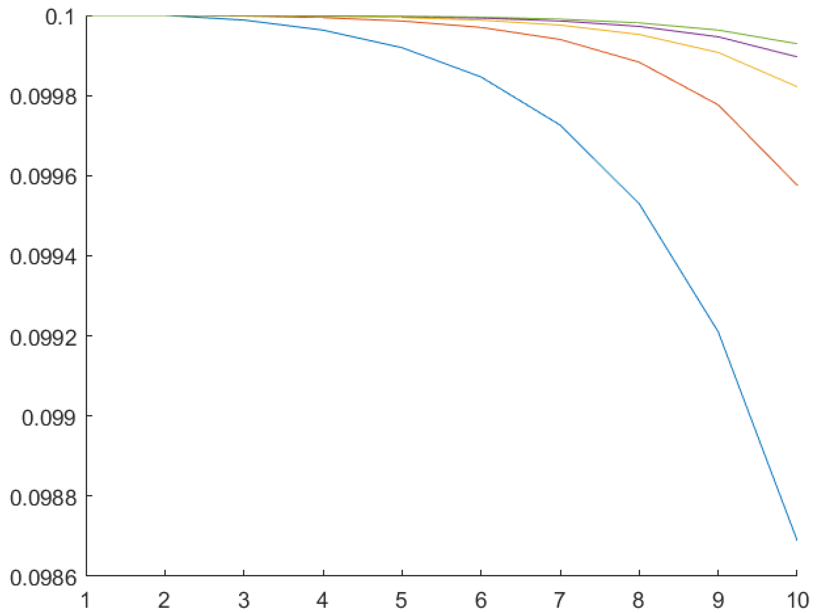
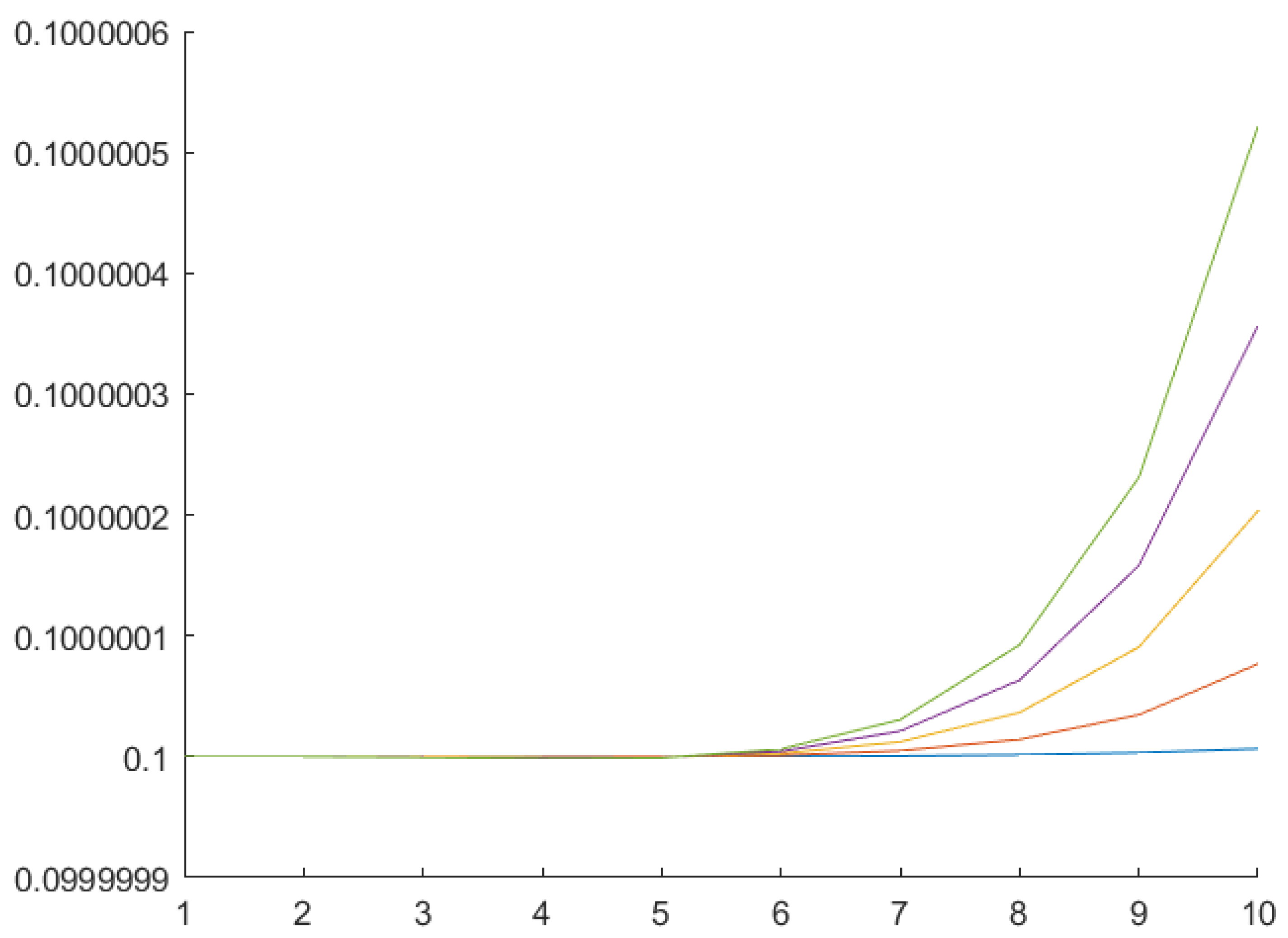
The time is a critical for the vibration dampening. Therefore the rate of “feather” angle change is a vital control law performance characteristic.
The control laws (21), Figure 5, and (24), Figure 6, minimize the “feather” angles while the control law (16), Figure 7 tends to maximize the “feather” angles under given conditions. Multiagent (21) and non-multiagent (24) control treat the “feathers” separately and the difference between them lies in usage of the information from neighboring “feathers” in process of the control action synthesis. In the case of multiagent control each “feather” “takes into account” the angles of its neighbors, allowing to achieve a faster control law.
The simulation of the considered multiagent system behavior requires substantial computations. However, the difference in the performance becomes apparent even in the first time steps. It could be seen from the graphs in Figure 5 and Figure 6 that the multiagent control law (in Figure 6) minimizes much better the “feather” angles.
7. Conclusions and Outlook
This work is our first study related to multiagent control of the wing with “feathers” aimed to avoid increasing wing oscillations when approaching the flutter. The main contributions of the article are:
- a mathematical model of the bending-torsional vibrations of an airplane wing with controlled “feathers” on its surface was constructed;
- three different conditions of the control problem corresponding to distinct subject functions were considered;
The multiagent approach was demonstrated to be useful in controlling complex network systems.
The control (20) is an “intermediate” one for synthesizing a multiagent control law. It has a similar structure to (16), but takes into account the presence of other “feathers” and their contribution. However, the information about them remains static. It means that the state and dynamics of other agents is not considered. The multiagent control law allows for each “feather” to take into account information about its own current state and about the current state of “feathers” in a wing area where it is located. As a rule, this allows a more precise tuning and a quicker adjustment to external factors, making this control law the most promising.
In the future, we plan to study the effectiveness of the obtained control laws and to compare them. The most critical indicator in the comparison should be the time needed to damp vibrations. The relevance of this indicator consists of the relatively fast process of oscillations increasing during flutter. Another promising area for further research is the development of multiagent control of “feathers” following the example of a swarm and researching its effectiveness.
Author Contributions
Conceptualization, O.G.; Software, Y.I.; Writing—original draft, D.S.; Writing—review & editing, Z.V. All authors have read and agreed to the published version of the manuscript.
Funding
Institutional Review Board Statement
Not applicable.
Informed Consent Statement
Not applicable.
Data Availability Statement
Not applicable.
Conflicts of Interest
The authors declare no conflict of interest.
References
- Byushgens, G.S. Aerodinamika i Dinamika Poleta Magistralnykh Samoletov [Aerodynamics and Flight Dynamics of Long Haul Aircraft]; Izdatel’skii otdel TsAGI–Avia-Izdatel’stvo KNR: Moscow-Pekin, Russian, 1995; 774p. [Google Scholar]
- Wright, J.R.; Jonathan, E.C. Introduction to Aircraft Aeroelasticity and Loads; John Wiley & Sons: Hoboken, NJ, USA, 2008; Volume 20. [Google Scholar]
- Fung, Y.C. An Introduction to the Theory of Aeroelasticity; Courier Dover Publications: Mineola, NY, USA, 2008. [Google Scholar]
- Livne, E. Aircraft active flutter suppression: State of the art and technology maturation needs. J. Aircr. 2018, 55, 410–450. [Google Scholar] [CrossRef]
- Bisplinghoff, R.L.; Ashley, H.; Halfman, R.L. Aeroelasticity; Addison-Wesley: Reading, MA, USA, 1955; 527p. [Google Scholar]
- Ashley, H. Flutter suppression within reach. Aerosp. Am. 1988, 26, 14–16. [Google Scholar]
- Bendiksen, O.O. Energy approach to flutter suppression and aeroelastic control. J. Guid. Control Dyn. 2001, 24, 176–184. [Google Scholar] [CrossRef]
- Freymann, R. New simplified ways to understand the interaction between aircraft structure and active control systems. In Proceedings of the 17th Fluid Dynamics, Plasma Dynamics, and Lasers Conference, Snowmass, CO, USA, 25–27 June 1984; p. 1868. [Google Scholar]
- Wykes, J. Structural dynamic stability augmentation and gust alleviation of flexible aircraft. In Proceedings of the 5th Annual Meeting and Technical Display, Philadelphia, PA, USA, 21–24 October 1968; p. 1067. [Google Scholar]
- Preumont, A. Vibration Control of Active Structures—An Introduction, 2nd ed.; Chapter 13; Kluwer Academic: Norwell, MA, USA, 2002; pp. 101–103. [Google Scholar]
- Livne, E. Integrated aeroservoelastic optimization: Status and progress. J. Aircr. 1999, 36, 122–145. [Google Scholar] [CrossRef]
- Vepa, R. Active flutter suppression by feedback compensation of transport lags. J. Guid. Control Dyn. 2007, 30, 879–882. [Google Scholar] [CrossRef]
- Leylek, E.A.; Costello, M. Use of compliant hinges to tailor flight dynamics of unmanned aircraft. J. Aircr. 2015, 52, 1692–1706. [Google Scholar] [CrossRef] [Green Version]
- Bollay, W. Aerodynamic stability and automatic control: The fourteenth wright brothers lecture. J. Aeronaut. Sci. 1951, 18, 569–617. [Google Scholar] [CrossRef]
- Roskam, J. Airplane Flight Dynamics and Automatic Flight Controls, Parts I and II; DARcorporation: Lawrence, KS, USA, 2013. [Google Scholar]
- Schmidt, D.K. Modern Flight Dynamics; McGraw–Hill: New York, NY, USA, 2012. [Google Scholar]
- Wykes, J.H.; Lawrence, R.E. Aerothermoelasticity: Its impact on stability and control of winged aerospace vehicles. J. Aircr. 1965, 2, 517–526. [Google Scholar] [CrossRef]
- Nicolai, L.; Hunten, K.; Zink, P.S.; Flick, P. System benefits of active flutter suppression for a sensorcraft-type vehicle. In Proceedings of the 13th AIAA/ISSMO Multidisciplinary Analysis Optimization Conference, Fort Worth, TX, USA, 13–15 September 2010; p. 9349. [Google Scholar]
- Huang, R.; Hu, H.Y.; Zhao, Y.H. Single-input/single-output adaptive flutter suppression of a three-dimensional aeroelastic system. J. Guid. Control Dyn. 2012, 35, 659–665. [Google Scholar] [CrossRef]
- Lee, K.W.; Singh, S.N. Multi-input noncertainty-equivalent adaptive control of an aeroelastic system. J. Guid. Control Dyn. 2010, 33, 1451–1460. [Google Scholar] [CrossRef]
- Zeng, J.; Wang, J.; de Callafon, R.; Brenner, M. Suppression of the aeroelastic/aeroservoelastic interaction using adaptive feedback control instead of notching filters. In Proceedings of the AIAA Atmospheric Flight Mechanics Conference, Portland, Oregon, 8–11 August 2011; p. 6459. [Google Scholar]
- Nguyen, N.T.; Swei, S.-M. Adaptive linear quadratic gaussian optimal control modification for flutter suppression of adaptive wing. In Proceedings of the AIAA Infotech @ Aerospace, Kissimmee, FL, USA, 5–9 January 2015; p. 0118. [Google Scholar]
- Lee, K.W.; Singh, S.N. Adaptive control of multi-input aeroelastic system with constrained inputs. J. Guid. Control Dyn. 2015, 38, 2337–2350. [Google Scholar] [CrossRef]
- Danowsky, B.P.; Thompson, P.M.; Lee, D.C.; Brenner, M. Modal Isolation and damping for adaptive aeroservoelastic suppression. In Proceedings of the AIAA Atmospheric Flight Mechanics (AFM) Conference, Boston, MA, USA, 19–22 August 2013; p. 4743. [Google Scholar]
- Nissim, E. Controller reduction using normal coordinates of reconstruction error matrix and component cost analysis method. J. Guid. Control Dyn. 1997, 20, 826–828. [Google Scholar] [CrossRef]
- Balakrishnan, A.V. Aeroelasticity, the Continuum Theory; Springer: New York, NY, USA, 2012. [Google Scholar]
- Platanitis, G.; Strganac, T.W. Control of a nonlinear wing section using leading- and trailing-edge surfaces. J. Guid. Control Dyn. 2004, 27, 52–58. [Google Scholar] [CrossRef] [Green Version]
- Xiang, J.; Yan, Y.; Li, D. Recent advance in nonlinear aeroelastic analysis and control of the aircraft. Chin. J. Aeronaut. 2014, 27, 12–22. [Google Scholar] [CrossRef] [Green Version]
- Mannarino, A.; Dowell, E.H.; Mantegazza, P. An adaptive controller for nonlinear flutter suppression and free-play compensation. J. Vib. Control 2015, 23, 2269–2290. [Google Scholar] [CrossRef]
- Tantaroudas, N.D.; Da Ronch, A.; Gai, G.; Badcock, K.J. An adaptive aeroelastic control approach using non linear reduced order models. In Proceedings of the 14th AIAA Aviation Technology, Integration, and Operations Conference, Atlanta, GA, USA, 16–20 June 2014; p. 2590. [Google Scholar]
- Singh, K.V.; McDonough, L.A.; Kolonay, R.; Cooper, J. Receptance based active aeroelastic control using multiple control surfaces. J. Aircr. 2014, 51, 335–342. [Google Scholar] [CrossRef]
- Amelina, N.; Granichin, O.; Kornivetc, A. Local Voting Protocol in decentralized load balancing problem with switched topology, noise, and delays. In Proceedings of the 52nd IEEE Conference on Decision and Control, Firenze, Italy, 10–13 December 2013; pp. 4613–4618. [Google Scholar]
- Amelina, N.; Granichin, O.; Granichina, O.; Ivanskiy, Y.; Jiang, Y. Optimal step-size of a local voting protocol for differentiated consensuses achievement in a stochastic network with priorities. In Proceedings of the 2015 European Control Conference, Linz, Austria, 15–17 July 2015; pp. 628–633. [Google Scholar]
- Amelin, K.; Granichin, O.; Sergeenko, A.; Volkovich, Z.V. Emergent intelligence via self-organization in group of robotics devices. Mathematics. 2021, 9, 1314. [Google Scholar] [CrossRef]
- Weiss, G. (Ed.) Multiagent Systems: A Modern Approach to Distributed Artificial Intelligence; MIT Press: Cambridge, MA, USA, 1999. [Google Scholar]
- Olfati-Saber, R.; Fax, J.A.; Murray, R.M. Consensus and cooperation in networked multi-agent systems. Proc. IEEE 2007, 95, 215–233. [Google Scholar] [CrossRef] [Green Version]
- Aleksandrov, A.; Fradkov, A.; Semenov, A. Delayed and switched control of formations on a line segment: Delays and switches do not matter. IEEE Trans. Autom. Control 2020, 65, 794–800. [Google Scholar] [CrossRef]
- Parsegov, S.; Polyakov, A.; Shcherbakov, P. Nonlinear fixed time control protocol for uniform allocation of agents on a segment. In Proceedings of the 51st IEEE Conference on Decision and Control (CDC), Maui, HI, USA, 10–13 December 2012; pp. 7732–7737. [Google Scholar]
- Shang, Y. Resilient consensus in multi-agent systems with state constraints. Automatica 2020, 122, 109288. [Google Scholar] [CrossRef]
- Granichin, O.; Khantuleva, T.; Granichina, O. Local voting protocol for the adaptation of airplane’s “feathers” in a turbulence flow. In Proceedings of the 2017 American Control Conference (ACC), Seattle, WA, USA, 24–26 May 2017; pp. 5684–5689. [Google Scholar]
- Granichin, O.N.; Khantuleva, T.A. Adapting wing elements (feathers) of an airplane in a turbulent flow with a multiagent protocol. Autom Remote Control 2017, 78, 1867–1882. [Google Scholar] [CrossRef]
- Amelin, K.; Amelina, N.; Granichin, O.; Granichina, O.; Ivanskiy, Y. Synchronization of multi-agent system of “feathers” on the surface of the wing in a turbulent airflow. In Proceedings of the 2019 IEEE Conference on Control Technology and Applications (CCTA), Hong Kong, China, 19–21 August 2019; pp. 355–359. [Google Scholar]
- Proskurnikov, A.; Granichin, O. Evolution of clusters in large-scale dynamical networks. Cybern. Phys. 2018, 7, 102–129. [Google Scholar] [CrossRef] [Green Version]
- Granichin, O.; Uzhva, D.; Volkovich, Z. Cluster flows and multiagent technology. Mathematics 2021, 9, 22. [Google Scholar] [CrossRef]
- Granichin, O.; Uzhva, D. Cluster control of complex cyber-physical systems. Cybern. Phys. 2021, 10, 191–200. [Google Scholar]
- Grossman, E.P. A Course in Vibrations in Parts of Aircraft; Oborongiz: Moscow, Russia, 1940; 312p. (In Russian) [Google Scholar]
- Fradkov, A.L. Cybernetical Physics: From Control of Chaos to Quantum Control; Springer: Berlin/Heidelberg, Germany, 2007. [Google Scholar]
- Fradkov, A.L. Speed-Gradient scheme and its application in adaptive control problems. Autom. Remote Control 1979, 40, 1333–1342. [Google Scholar]
- Shang, Y.; Ye, Y. Fixed-time group tracking control with unknown inherent nonlinear dynamics. IEEE Access 2017, 5, 12833–12842. [Google Scholar] [CrossRef]
Figure 1.
Wing with “feathers”.

Figure 2.
Stiffness Centers and Gravity Centers lines on a wing, where is the elastic axis containing the stiffness centers of the wing section; X-axis is codirectional with steady airflow V; Z-axis is directed along the elastic axis of the undeformed wing; Y-axis complements the coordinate system in the vertical direction; is the distance from the leading edge of the wing to the SC section; is the distance between SC and GC; h is the transverse deflection of the section ; l is the half-span of the wing.

Figure 3.
Wing cross-section.

Figure 4.
Wing profiles in a static position and during vibrations.

Figure 5.
“Feather” angles change under the non-multiagent control law (21).
Figure 5.
“Feather” angles change under the non-multiagent control law (21).

Figure 6.
“Feather” angles change under the multiagent control law (24).
Figure 6.
“Feather” angles change under the multiagent control law (24).

Figure 7.
“Feather” angles change under the control (16).
Figure 7.
“Feather” angles change under the control (16).

Publisher’s Note: MDPI stays neutral with regard to jurisdictional claims in published maps and institutional affiliations. |
© 2022 by the authors. Licensee MDPI, Basel, Switzerland. This article is an open access article distributed under the terms and conditions of the Creative Commons Attribution (CC BY) license (https://creativecommons.org/licenses/by/4.0/).
Share and Cite
MDPI and ACS Style
Shalymov, D.; Granichin, O.; Ivanskiy, Y.; Volkovich, Z. Multiagent Control of Airplane Wing Stability with “Feathers” under the Flexural Torsional Flutter. Mathematics 2022, 10, 236. https://doi.org/10.3390/math10020236
AMA Style
Shalymov D, Granichin O, Ivanskiy Y, Volkovich Z. Multiagent Control of Airplane Wing Stability with “Feathers” under the Flexural Torsional Flutter. Mathematics. 2022; 10(2):236. https://doi.org/10.3390/math10020236
Chicago/Turabian StyleShalymov, Dmitry, Oleg Granichin, Yury Ivanskiy, and Zeev Volkovich. 2022. "Multiagent Control of Airplane Wing Stability with “Feathers” under the Flexural Torsional Flutter" Mathematics 10, no. 2: 236. https://doi.org/10.3390/math10020236
Note that from the first issue of 2016, this journal uses article numbers instead of page numbers. See further details here.