
High-Strength Copper/Silver Alloys Processed by Cold Spraying for DC and Pulsed High Magnetic Fields
 , , , and
Abstract
:1. Introduction
2. Experimental Procedure
2.1. Powder Preparation
2.2. Cold-Spray Deposition
2.3. Wire Preparation
2.4. Characterization
2.4.1. Microstructure
2.4.2. Macroscopic Properties of Cu/5Ag Bulk Material
2.4.3. Macroscopic Properties of Cu/5Ag Wires
3. Results and Discussion
3.1. Microstructure
3.2. Mechanical Properties and Electrical Resistivity
3.2.1. Bulk Material
3.2.2. Wires
4. Conclusions
Author Contributions
Funding
Institutional Review Board Statement
Informed Consent Statement
Data Availability Statement
Acknowledgments
Conflicts of Interest
References
- Pugnat, P.; Barbier, R.; Berriaud, C.; Berthier, R.; Boujet, T.; Graffin, P.; Grandclement, C.; Hervieu, B.; Jousset, J.; Juster, F.P.; et al. 43 + T Grenoble Hybrid Magnet: From Final Assembly to Commissioning of the Superconducting Outsert. IEEE Trans. Appl. Supercond. 2022, 32, 4300607. [Google Scholar] [CrossRef]
- Beard, J.; Billette, J.; Ferreira, N.; Frings, P.; Lagarrigue, J.-M.; Lecouturier, F.; Nicolin, J.-P. Design and Tests of the 100-T Triple Coil at LNCMI. IEEE Trans. Appl. Supercond. 2017, 28, 4300305. [Google Scholar] [CrossRef]
- Sakai, Y.; Inoue, K.; Asano, T.; Wada, H.; Maeda, H. Development of high-strength, high-conductivity Cu–Ag alloys for high-field pulsed magnet use. Appl. Phys. Lett. 1991, 59, 2965–2967. [Google Scholar] [CrossRef]
- Han, K.; Baca, A.; Coe, H.; Embury, J.; Kihara, K.; Lesch, B.; Li, L.; Schillig, J.; Sims, J.; Van Sciver, S.; et al. Material issues in the 100 T non-destructive magnet. IEEE Trans. Appl. Supercond. 2000, 10, 1277–1280. [Google Scholar] [CrossRef]
- Han, K.; Embury, J.; Sims, J.; Campbell, L.; Schneider-Muntau, H.-J.; Pantsyrnyi, V.; Shikov, A.; Nikulin, A.; Vorobieva, A. The fabrication, properties and microstructure of Cu–Ag and Cu–Nb composite conductors. Mater. Sci. Eng. A 1999, 267, 99–114. [Google Scholar] [CrossRef]
- Zuo, X.; Han, K.; Zhao, C.; Niu, R.; Wang, E. Microstructure and properties of nanostructured Cu28 wt%Ag microcomposite deformed after solidifying under a high magnetic field. Mater. Sci. Eng. A 2014, 619, 319–327. [Google Scholar] [CrossRef]
- Coddet, P.; Verdy, C.; Coddet, C.; Debray, F. Effect of cold work, second phase precipitation and heat treatments on the mechanical properties of copper–silver alloys manufactured by cold spray. Mater. Sci. Eng. A 2015, 637, 40–47. [Google Scholar] [CrossRef]
- Coddet, P.; Verdy, C.; Coddet, C.; Debray, F. On the mechanical and electrical properties of copper-silver and copper-silver-zirconium alloys deposits manufactured by cold spray. Mater. Sci. Eng. A 2016, 662, 72–79. [Google Scholar] [CrossRef]
- Jay, O.; Verdy, C.; Trophime, C.; Danlos, Y.; Debray, F. Cold Spray Manufacturing for Structural Materials for High Field Magnet Production. Mater. Sci. Forum 2018, 941, 1540–1545. [Google Scholar] [CrossRef]
- Tardieu, S.; Mesguich, D.; Lonjon, A.; Lecouturier, F.; Ferreira, N.; Chevallier, G.; Proietti, A.; Estournès, C.; Laurent, C. Nanostructured 1% silver-copper composite wires with a high tensile strength and a high electrical conductivity. Mater. Sci. Eng. A 2019, 761, 138048. [Google Scholar] [CrossRef]
- Tardieu, S.; Mesguich, D.; Lonjon, A.; Lecouturier-Dupouy, F.; Ferreira, N.; Chevallier, G.; Proietti, A.; Estournès, C.; Laurent, C. Influence of alloying on the tensile strength and electrical resistivity of silver nanowire: Copper composites macroscopic wires. J. Mater. Sci. 2020, 56, 4884–4895. [Google Scholar] [CrossRef]
- Tardieu, S.; Mesguich, D.; Lonjon, A.; Lecouturier-Dupouy, F.; Ferreira, N.; Chevallier, G.; Proietti, A.; Estournès, C.; Laurent, C. Influence of bimodal copper grain size distribution on electrical resistivity and tensile strength of silver–copper composite wires. Mater. Today Commun. 2023, 37, 107403. [Google Scholar] [CrossRef]
- Schmidt, T.; Gärtner, F.; Assadi, H.; Kreye, H. Development of a generalized parameter window for cold spray deposition. Acta Mater. 2006, 54, 729–742. [Google Scholar] [CrossRef]
- Assadi, H.; Kreye, H.; Gärtner, F.; Klassen, T. Cold spraying–A materials perspective. Acta Mater. 2016, 116, 382–407. [Google Scholar] [CrossRef]
- Hassani-Gangaraj, M.; Veysset, D.; Nelson, K.A.; Schuh, C.A. In-situ observations of single micro-particle impact bonding. Scr. Mater. 2018, 145, 9–13. [Google Scholar] [CrossRef]
- Hassani-Gangaraj, M.; Veysset, D.; Champagne, V.K.; Nelson, K.A.; Schuh, C.A. Adiabatic shear instability is not necessary for adhesion in cold spray. Acta Mater. 2018, 158, 430–439. [Google Scholar] [CrossRef]
- Assadi, H.; Gärtner, F.; Stoltenhoff, T.; Kreye, H. Bonding mechanism in cold gas spraying. Acta Mater. 2003, 51, 4379–4394. [Google Scholar] [CrossRef]
- Grujicic, M.; Zhao, C.; DeRosset, W.; Helfritch, D. Adiabatic shear instability based mechanism for particles/substrate bonding in the cold-gas dynamic-spray process. Mater. Des. 2004, 25, 681–688. [Google Scholar] [CrossRef]
- Luo, X.-T.; Li, C.-X.; Shang, F.-L.; Yang, G.-J.; Wang, Y.-Y.; Li, C.-J. High velocity impact induced microstructure evolution during deposition of cold spray coatings: A review. Surf. Coat. Technol. 2014, 254, 11–20. [Google Scholar] [CrossRef]
- Chaudhuri, A.; Raghupathy, Y.; Srinivasan, D.; Suwas, S.; Srivastava, C. Microstructural evolution of cold-sprayed Inconel 625 superalloy coatings on low alloy steel substrate. Acta Mater. 2017, 129, 11–25. [Google Scholar] [CrossRef]
- Liu, T.; Leazer, J.D.; Brewer, L.N. Particle deformation and microstructure evolution during cold spray of individual Al-Cu alloy powder particles. Acta Mater. 2019, 168, 13–23. [Google Scholar] [CrossRef]
- Rokni, M.; Widener, C.; Crawford, G. Microstructural evolution of 7075 Al gas atomized powder and high-pressure cold sprayed deposition. Surf. Coat. Technol. 2014, 251, 254–263. [Google Scholar] [CrossRef]
- Huang, R.; Sone, M.; Ma, W.; Fukanuma, H. The effects of heat treatment on the mechanical properties of cold-sprayed coatings. Surf. Coat. Technol. 2015, 261, 278–288. [Google Scholar] [CrossRef]
- Qiu, X.; Wang, J.-Q.; Tariq, N.U.H.; Gyansah, L.; Zhang, J.-X.; Xiong, T.-Y. Effect of Heat Treatment on Microstructure and Mechanical Properties of A380 Aluminum Alloy Deposited by Cold Spray. J. Therm. Spray Technol. 2017, 26, 1898–1907. [Google Scholar] [CrossRef]


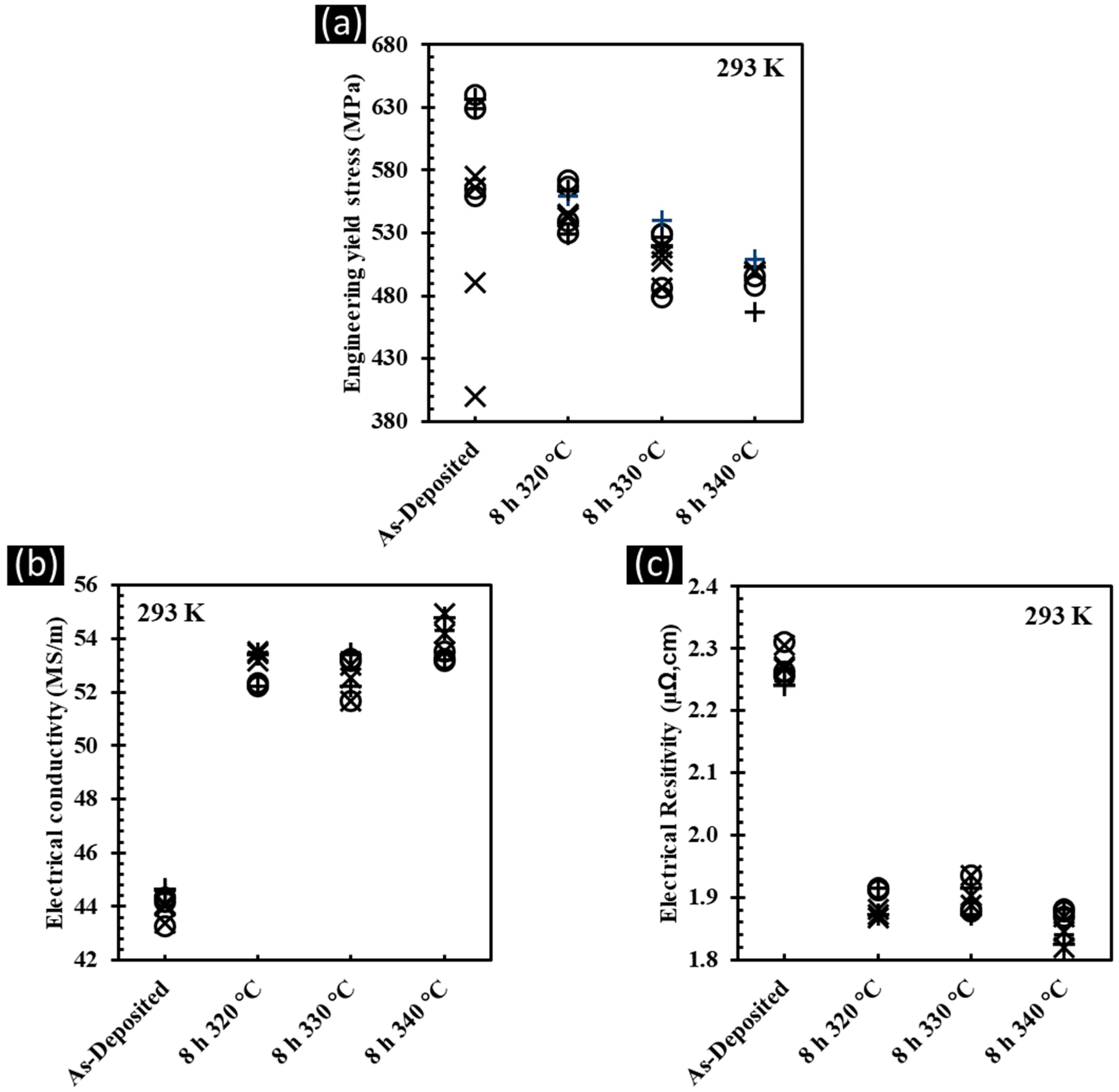
 ), tangential (
 ), and longitudinal (
 ) directions.
), tangential (), and longitudinal () directions.
) directions.
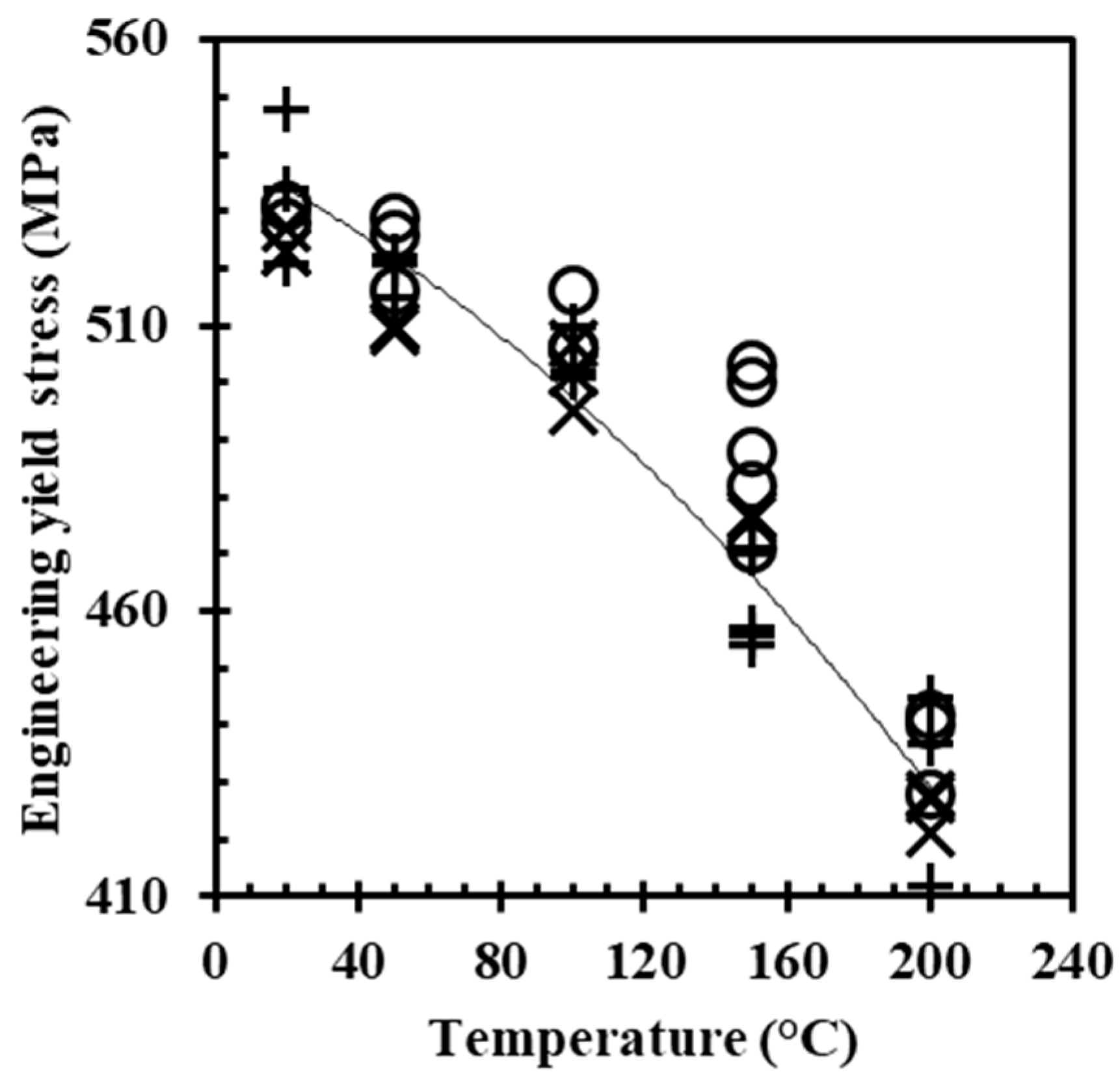
), tangential (), and longitudinal () directions. ), tangential (), and longitudinal () directions with temperature for the Cu/5Ag CS-deposited material with an 8 h heat treatment at 330 °C.
), tangential (), and longitudinal () directions with temperature for the Cu/5Ag CS-deposited material with an 8 h heat treatment at 330 °C.
), tangential (), and longitudinal () directions with temperature for the Cu/5Ag CS-deposited material with an 8 h heat treatment at 330 °C.


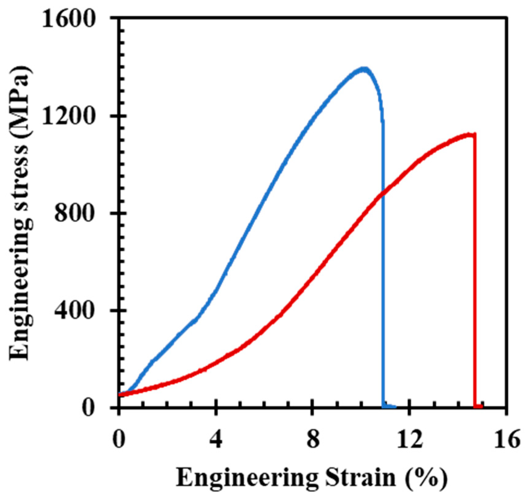
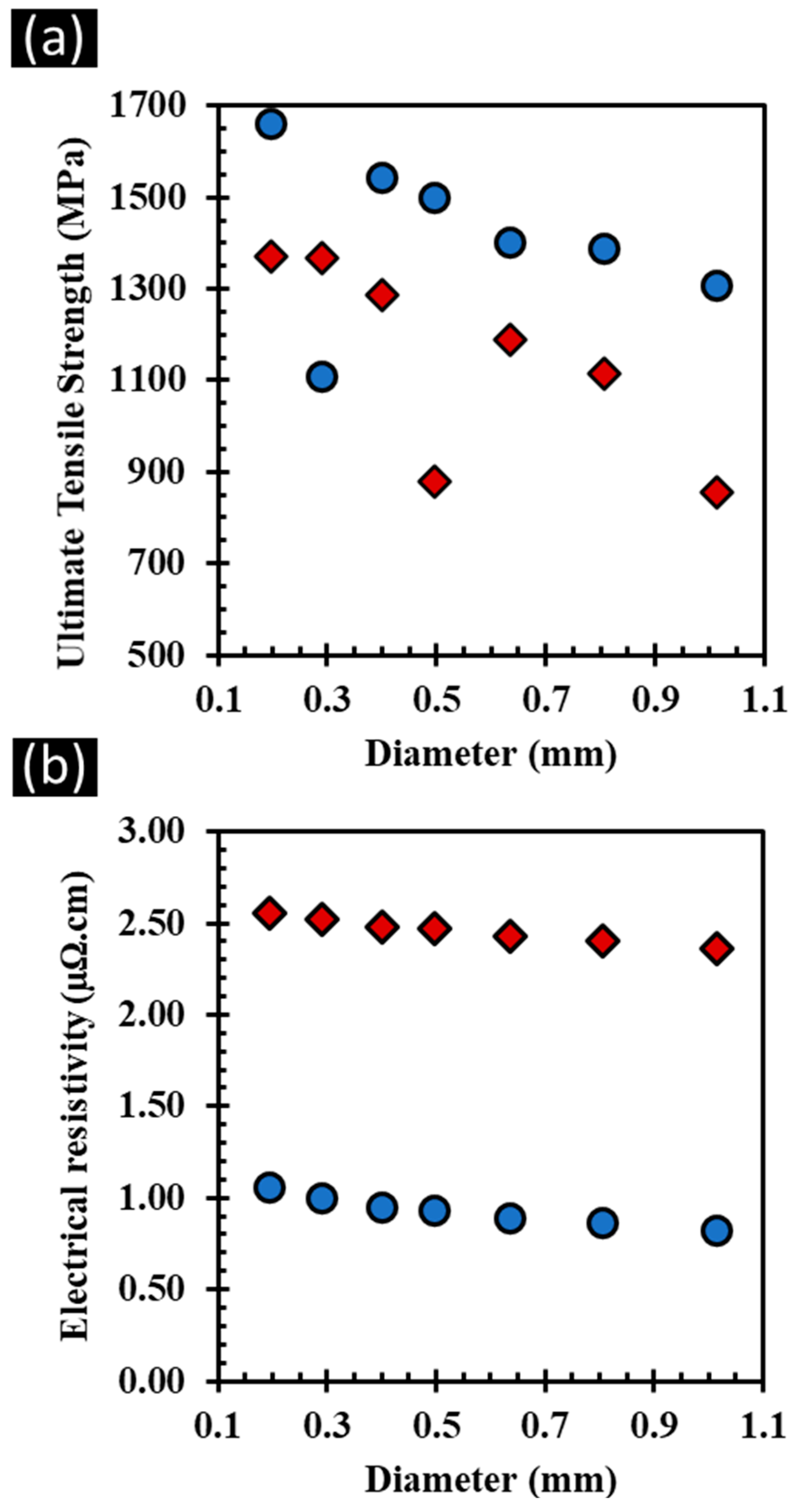
 ) and 77 K (
 ) for present wires.
) and 77 K () for present wires.
) for present wires.
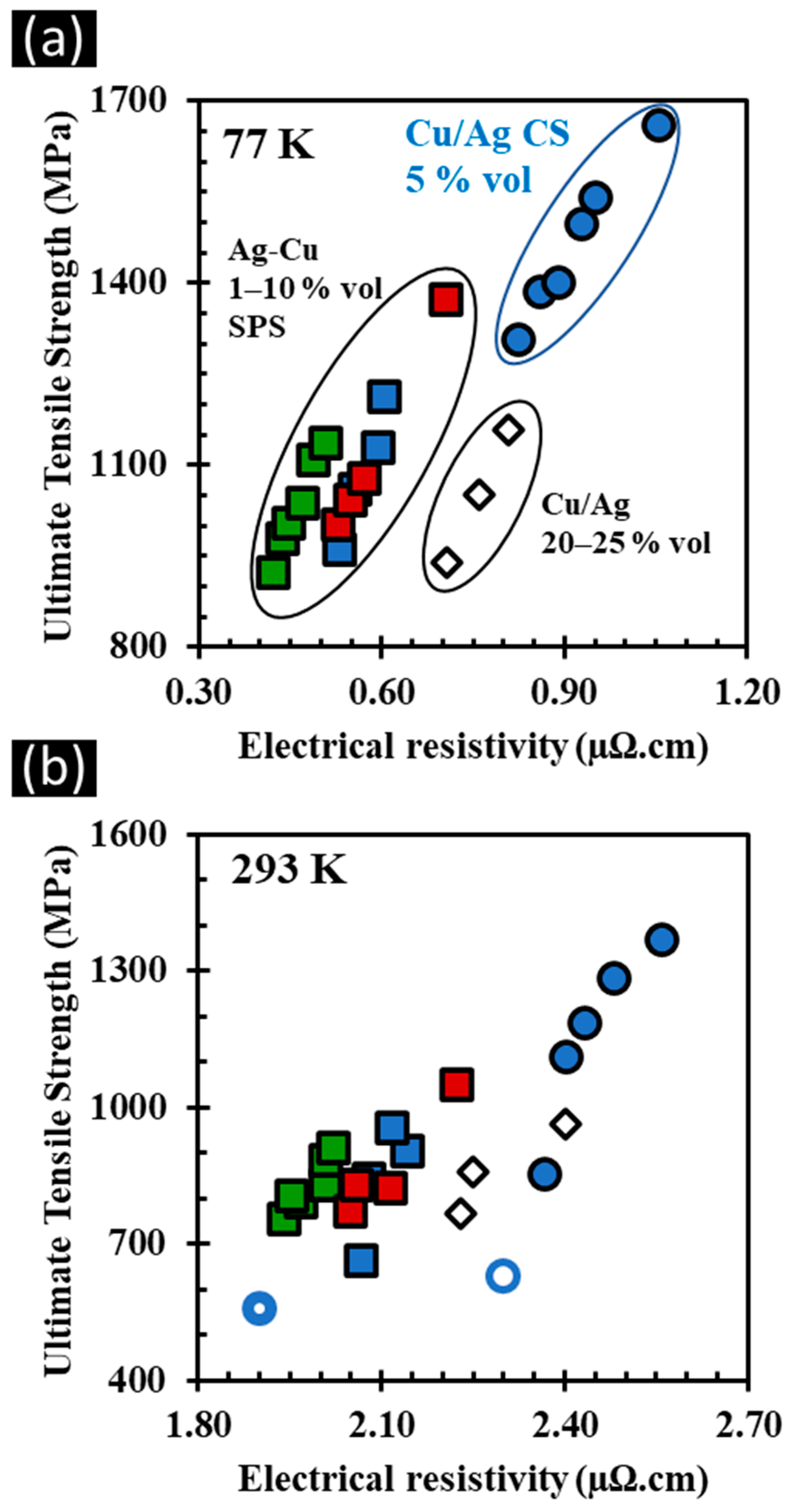
) and 77 K () for present wires. ) and bulk CS as-deposited (
 ) and heat-treated (
 ) SPS composite Ag-Cu (1, 5, and 10 vol. % Ag) wires (
 ,
,  ,
,  ) [10] and alloyed Cu/Ag (21–25 vol. % Ag) wires (
 ) [4,5,6].

| Wire Diameter (mm) | Electrical Resistivity (µΩ·cm) | Ultimate Tensile Strength (MPa) | ||
|---|---|---|---|---|
| 293 K | 77 K | 293 K | 77 K | |
| 1.0 | 2.37 | 0.82 | 855 * | 1307 |
| 0.8 | 2.40 | 0.86 | 1115 | 1387 |
| 0.6 | 2.43 | 0.89 | 1187 | 1401 |
| 0.5 | 2.47 | 0.93 | 879 * | 1499 |
| 0.4 | 2.48 | 0.95 | 1286 | 1541 |
| 0.3 | 2.52 | 1.00 | 1366 | 1108 * |
| 0.2 | 2.56 | 1.05 | 1372 | 1660 |
Disclaimer/Publisher’s Note: The statements, opinions and data contained in all publications are solely those of the individual author(s) and contributor(s) and not of MDPI and/or the editor(s). MDPI and/or the editor(s) disclaim responsibility for any injury to people or property resulting from any ideas, methods, instructions or products referred to in the content. |
© 2024 by the authors. Licensee MDPI, Basel, Switzerland. This article is an open access article distributed under the terms and conditions of the Creative Commons Attribution (CC BY) license (https://creativecommons.org/licenses/by/4.0/).
Share and Cite
Tardieu, S.; Idrir, H.; Verdy, C.; Jay, O.; Ferreira, N.; Debray, F.; Joulain, A.; Tromas, C.; Thilly, L.; Lecouturier-Dupouy, F. High-Strength Copper/Silver Alloys Processed by Cold Spraying for DC and Pulsed High Magnetic Fields. Magnetochemistry 2024, 10, 15. https://doi.org/10.3390/magnetochemistry10030015
Tardieu S, Idrir H, Verdy C, Jay O, Ferreira N, Debray F, Joulain A, Tromas C, Thilly L, Lecouturier-Dupouy F. High-Strength Copper/Silver Alloys Processed by Cold Spraying for DC and Pulsed High Magnetic Fields. Magnetochemistry. 2024; 10(3):15. https://doi.org/10.3390/magnetochemistry10030015
Chicago/Turabian StyleTardieu, Simon, Hanane Idrir, Christophe Verdy, Olivier Jay, Nelson Ferreira, François Debray, Anne Joulain, Christophe Tromas, Ludovic Thilly, and Florence Lecouturier-Dupouy. 2024. "High-Strength Copper/Silver Alloys Processed by Cold Spraying for DC and Pulsed High Magnetic Fields" Magnetochemistry 10, no. 3: 15. https://doi.org/10.3390/magnetochemistry10030015