
Fast Attitude Estimation System for Unmanned Ground Vehicle Based on Vision/Inertial Fusion


1
Xi’an Modern Control Technology Research Institute, Xi’an 710065, China
2
CSGC Key Laboratory of Intelligent Ammunition System, Xi’an 710065, China
*
Author to whom correspondence should be addressed.
Machines 2021, 9(10), 241; https://doi.org/10.3390/machines9100241
Submission received: 11 August 2021
/
Revised: 27 September 2021
/
Accepted: 14 October 2021
/
Published: 18 October 2021
(This article belongs to the Special Issue Nonlinear and Optimal, Real-Time Control of UAV)
Abstract
:The attitude estimation system based on vision/inertial fusion is of vital importance and great urgency for unmanned ground vehicles (UGVs) in GNSS-challenged/denied environments. This paper aims to develop a fast vision/inertial fusion system to estimate attitude; which can provide attitude estimation for UGVs during long endurance. The core idea in this paper is to integrate the attitude estimated by continuous vision with the inertial pre-integration results based on optimization. Considering that the time-consuming nature of the classical methods comes from the optimization and maintenance of 3D feature points in the back-end optimization thread, the continuous vision section calculates the attitude by image matching without reconstructing the environment. To tackle the cumulative error of the continuous vision and inertial pre-integration, the prior attitude information is introduced for correction, which is measured and labeled by an off-line fusion of multi-sensors. Experiments with the open-source datasets and in road environments have been carried out, and the results show that the average attitude errors are 1.11° and 1.96°, respectively. The road test results demonstrate that the processing time per frame is 24 ms, which shows that the proposed system improves the computational efficiency.
1. Introduction
The attitude estimation of unmanned ground vehicles (UGVs) plays an important role in autonomous navigation, rollover warning, and ride experience optimization. As a part of navigation information, attitude can be calculated by many navigation methods of unmanned vehicles, such as the strapdown inertial navigation system (SINS), vision navigation system, LiDAR navigation system, polarized light navigation system, or multi-sensor fusion system.
At present, UGVs rely more on the fusion of the global navigation satellite system (GNSS) and inertial navigation system (INS), which can estimate the attitude all-weather, all-day [1]. SINS can independently calculate the attitude independently, and its error accumulates over time. As GNSS can independently provide high-precision measurement information, using filtering methods such as the Kalman filter (KF), particle filter (PF), extended Kalman filter (EKF), etc. to combine them can achieve high-precision attitude estimation [2,3]. In general, GNSS/SINS integrated navigation systems work well when the GPS signal has not interfered. However, the GNSS signals might be affected by attenuation and multipath effects. In this case, how to design the attitude estimating system for UGVs is vital [4]. To tackle this, LiDAR is an ideal choice. Generally, LiDAR can provide for UGVs with incremental odometer information by accurate bearing and range measurements at high frequency [5,6]. Zhou et al. designed a computationally efficient LiDAR-odometry framework based on truncated least squares with a novel feature extraction module [7]. Nevertheless, the high cost of high-precision LiDAR prohibits its mass deployment in UGVs. Bionic polarized light orientation can be used to achieve the low-cost orientation for UGVs and when fused with IMU can achieve high precision [8]. However, the precision of orientation is influenced greatly by the atmospheric polarization mode errors and the horizontal attitude errors [9,10]; that is, its orient precision is not robust.
Except for LiDAR and polarized light, the optical camera is an effective sensor to aid the inertial, by which it can calculate the attitude. Due to its low cost, small size, and rich environmental perception information, it is a very promising scheme in engineering applications. At present, the vision/inertial fusion system can be divided into the method of filtering and optimization [11]. The method based on filtering is to use the visual calculation results to construct the measurement equation and use the inertial mechanization results to construct the state equation. Then the state and measurement equation are fused through the Kalman family filter. The method based on optimization is to construct the residuals of inertial pre-integration results and visual reprojection results, respectively. Then the navigation information consisting of the attitude information can be calculated through the optimization method. Zhai et al. proposed a robust fusion algorithm of vision and micro electromechanical system (MEMS), which apply the sliding window to design the measurement equation based on the epipolar geometry constraint and the tri-focal tensor constraint. To improve the accuracy of positioning, a new method of automatically estimating the DoA of UGV ego-motion uncertainty was utilized in the framework of UKF [12]. Yu et al. designed a camera-motion estimating method based on an innovative EKF algorithm. In the EKF, a constant-velocity motion model is used as the dynamic system, and the trifocal-tensor constraint is incorporated into the measurement model [13]. In the same integration way, Indelman et al. used three-view images to construct constraints, and a novel fusion method was designed based on IEKF with the results of SINS navigation. This method can output the attitude, speed, and position of the carrier in real time [14].
Compared with the optimized method, the optimization-based vision/inertial fusion method is the current mainstream, which has the advantages of efficiency, precision, and the possibility of achieving a large range of environments [11]. Forster et al. put forward a systematic theory for inertial pre-integration, which cleverly converts the previous inertial continuous mechanization results into incremental results. This theory provides a mature theoretical basis for inertial navigation to incrementally output navigation information and makes it possible for adding into the optimization framework [15]. Based on this, Qin et al. proposed an optimized vision/inertial fusion system termed VINS-mono [16]. In the back-end, the residual equation was constructed by the inertial pre-integration and vision reprojection errors to optimize the navigation information in the sliding window. Similarly, Campos proposed a similar vision/inertial fusion framework [17] based on [18]. These two methods are generally recognized as classical VIO algorithms and have been further studied by many scholars. Different from them, Venator et al. proposed a visual pose estimation method based on 3D reconstruction, which used visual semantic segmentation to eliminate dynamic feature points and GPS data to eliminate incorrect image association information [19].
In summary, the fusion of vision/inertial is a vital means for UGVs to estimate attitude, in which the fusion method based on optimization is the mainstream and has achieved a good comprehensive effect. However, its high computational cost prohibits its mass deployment in UGVs. To tackle this, an attitude estimation system is designed in this paper. The main contributions of this paper are summarized as follows.
- A fast attitude estimate system is proposed. Based on the optimization method, the MEMS pre-integration results and the continuous visual attitude calculation results are fused. In order to eliminate the accumulated error, the pre-measured offline attitude library is introduced to provide a high-precision value.
- The experimental comparison results demonstrate the computational efficiency of the proposed method, and the attitude error will not accumulate with the endurance.
The rest of this paper is organized as follows. In Section 2, the system model, fusion algorithm, and attitude library construction methods are introduced. In Section 3, we conduct experiments; the experimental results are discussed in Section 4. In Section 5, we summarize this paper and give the conclusion.
2. Materials and Methods
2.1. System Model
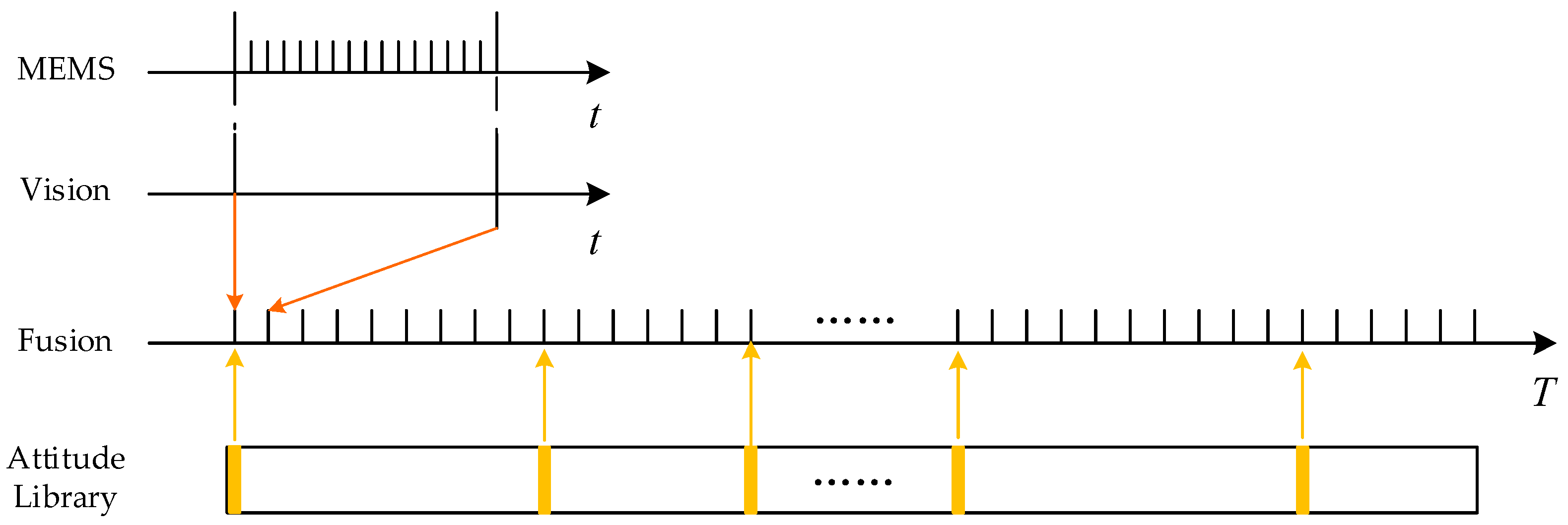
In this paper, a fast attitude estimate system based on the fusion of vision/inertial is proposed. Firstly, based on the optimization method, the MEMS pre-integration results and the continuous visual attitude estimation results are fused. As shown in Figure 1, based on consecutive image frames, the residual between two frames was constructed by utilizing the attitude estimation by the continuous vision and the inertial raw data. Then, the attitude between the two frames was calculated through optimization. Considering that inertial noise and calculation error of vision will inevitably cause the attitude errors accumulation over time, the pre-measured attitude libraries are introduced to ensure high accuracy in continuous endurance.
The system can be divided into three parts: the attitude estimation based on the vision/inertial fusion method is given in Section 2.2. The off-line attitude library construction method is given in Section 2.3. Finally, the platform of road test experiments designed in this paper is given in Section 2.4.
2.2. Attitude Estimate Based on the Vision/Inertial Fusion
Since the purpose of this paper is to estimate the attitude, there is no need to reconstruct the environment and the 3D position of feature points does not need to be calculated. Therefore, we only use the camera geometric constraints to form residual equations, thereby reducing the computational cost of the method [14,20]. So far, the attitude estimate theory of continuous visual has matured and the epipolar geometric constraint for attitude calculation can be expressed as:
where the matching points of satisfy Equation (1) and the fundamental matrix satisfies:
where is the camera intrinsics matrix, is the rotation matrix and is the translation matrix between two frames. According to Equation (2), the rotation matrix between two frames can be solved by constructing the parameters matrix through multiple matching points and performing SVD decomposition. Thus, it can be predicted that the accuracy of matching determines the accuracy of attitude, and the accuracy of matching is influenced by many factors such as light intensity, rotation, blur, scale change, and weak texture. Considering that ORB is a fast and robust feature among the current feature extraction algorithms and many research achievements have emerged up to now, this paper utilizes it as the extraction method. After applying the RSNSAC as the matching method, the attitude can be solved. Thus, given the attitude at i frame , we can obtain the attitude at j frame according to the solved rotation matrix between i and j frames. Furthermore, the attitude results can be used with the pre-integration of the MEMS to form the residual equation.
The pre-integration of MEMS from i to j can be expressed as:
where is the raw data of the MEMS and is the bias of the gyro at k frame. Then, the residual equation can be given as:
where and is the rotation matrix at i and j frame, respectively. is the deviation value of the gyro bias at i frame. According to Equation (4), the attitude information to be solved is . For the convenience of solving the residual equation, the optimization variables are set as . Thus, the partial derivative equation of with respect to them can be given as:
where is the right Jacobian matrix of the three-dimensional special orthogonal group. is the inverse mapping of the .
Thus, given the raw data of the gyro and the attitude estimation results of the consecutive images , the attitude residual equation can be formed. According to the partial derivative Equations (5)–(7), the optimization variables can be solved by the Gauss-Newton method; thus, the attitude can be updated.
It is obvious that if the attitude estimation results of consecutive vision work well, the attitude estimation results based on the vision/inertial fusion method are close to it. In this way, the error of the attitude estimation results will cumulative. To tackle this, this paper designs an off-line attitude library to calibrate the real-time image, as shown in Figure 1. The offline attitude library contains the calibrated image and the camera intrinsics matrix and attitude in the navigation frame. After the solution of Equation (2), high-precision attitude results can be obtained which are not related to time.
2.3. Off-Line Attitude Library Construction Method
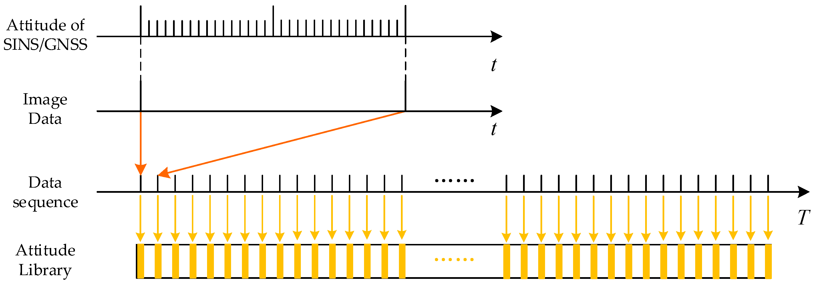
The off-line attitude libraries are constructed by multi-sensor fusion. As shown in Figure 2, a tightly fused SINS/GNSS method is designed to provide the library with accurate attitude in the navigation frame(E-N-U) firstly. Then, the vision/MEMS fused system is utilized to collect image data.
The liner system of SINS/GNSS can be expressed as:
where X(t) is the error-state vector of SINS, F(t) is the state transition matrix, r is the vector of process noise, q is the vector of measurement noise, Z(t) is the vector of measurement, and H(t) is the observation matrix constructed based on pseudo-range and pseudo-range rate. As expressed in (2), the state vector X has 17 dimensions, which are composed of 3-dim attitude errors, 3-dim velocity errors, 3-dim position errors, 3-dim gyroscope drifts, 3-dim accelerometer drifts, 1-dim pseudo-range error, and 1-dim pseudo-range rate error:
Based on the state vector, the state transition matrix F can be written as:
The measurement model can be calculated as:
where the is the pseudo-range measurement model and the is the pseudo-range rate measurement model. The is the transformation of velocity from the navigation frame system to the ECEF (Earth-Centered Earth-Fixed) frame:
where is the position of the SINS mechanization in navigation frame. In Equation (11), P is the retraction of:
where the vector is the position of the SINS mechanization in the ECEF frame which transformed from . The vector is the position of GNSS in the ECEF frame. The denotes the pseudo-range which can be given by GNSS receiver.
In Equation (11), the Q is the retraction of:
Given the true value of the SINS position and the pseudo-range ρ, the pseudo-range rate can be calculated as:
In Equation (11), the is the retraction of:
The is the retraction of the transformation between and :
Above is the calculation process of the system equation. Then, the time update step of the Kalman filter with feedback can be written as:
where, for the convenience of algorithmic calculation, the discrete form of error-state is expressed as: . The measurement update step of Kalman filter with feedback can be written as:
where Equations (16) and (17) are the standard Kalman filter process [21]. Note that when the multiple pseudo range and pseudo range rate data are received, multiple iterations are performed according to (19). Followed by the Kalman filter, the mechanization results are corrected by:
The integrated attitude results of SINS/GNSS only provides accurate attitude for the attitude library. The purpose of a tightly integrated method is to maintain a high-precision attitude, even when the GNSS fails for a short time.
Then, we can use the attitude results to build the attitude library. With the attitude library in the navigation frame, we can use it to correct the accumulated error of the proposed method by calculating the fundamental matrix .
2.4. Platform of Road Test Experiments
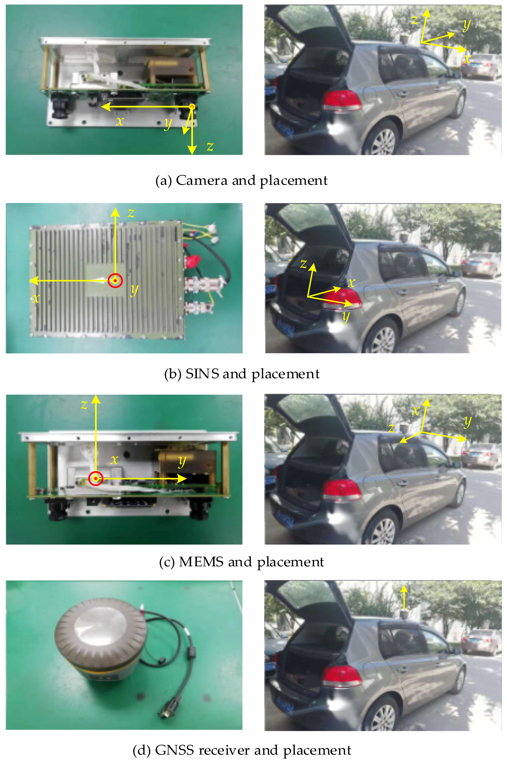
As shown in Figure 3, the platform of road test experiments consists of the Vehicle, Camera, SINS, MEMS, and GNSS, whose position and the coordinates are also given in Figure 3. The robot operating system (ROS) is the core operating system of the platform which completes the data alignment of the multi-sensors and the program operation of the multi sensors fusion. The CPU of the intel core i5-8600K is the core processor and all road test data are processed off-line.
3. Results
For verifying the accuracy and computational cost of the attitude estimation system, we conducted experiments using the KITTI dataset and urban road test data. The experimental results are given in Section 3.2 and Section 3.3, respectively. Furthermore, the parameters of sensors used for the road test are given in Section 3.1. Considering the similar performance of classical algorithms, for comparing the results of the experiments with the classical method conveniently, we chose the VI-ORBSLAM [22] as the classical method after the analysis in Section 1.
3.1. Parameters of Sensors
The proposed attitude estimation system consists of MEMS, sensor of vision, SINS, and GNSS, whose parameters are shown below.
- Parameters of MEMS.
The parameters of the MEMS are given in Table 1.
- Parameters of vision.
The sensor of vision is triggered by hardware and can generate an image with a resolution of 1250 ∗ 500 per 0.05 s.
- Parameters of SINS/GNSS.
Considering that the changes of the angular velocity are very slow in the road test environment, the attitudes error calculated by SINS/GNSS with a high-precision IMU is within 0.2°.
3.2. Experiments with KITTI Dataset
The experiments in the highway area were conducted using the KITTI dataset 2011_10_03_drive_0042 from raw sequence 000000 to sequence 001100. The trajectory was about 1384 m and average velocity was about 75.9 km/h [23]. For comparing the experiments results with the ground truth conveniently, we used the camera frame of the first frame as the navigation frame. Since there was no prior library with attitude labels, we took raw images every 100 frames to build a library and take the ground truth as the attitude value.
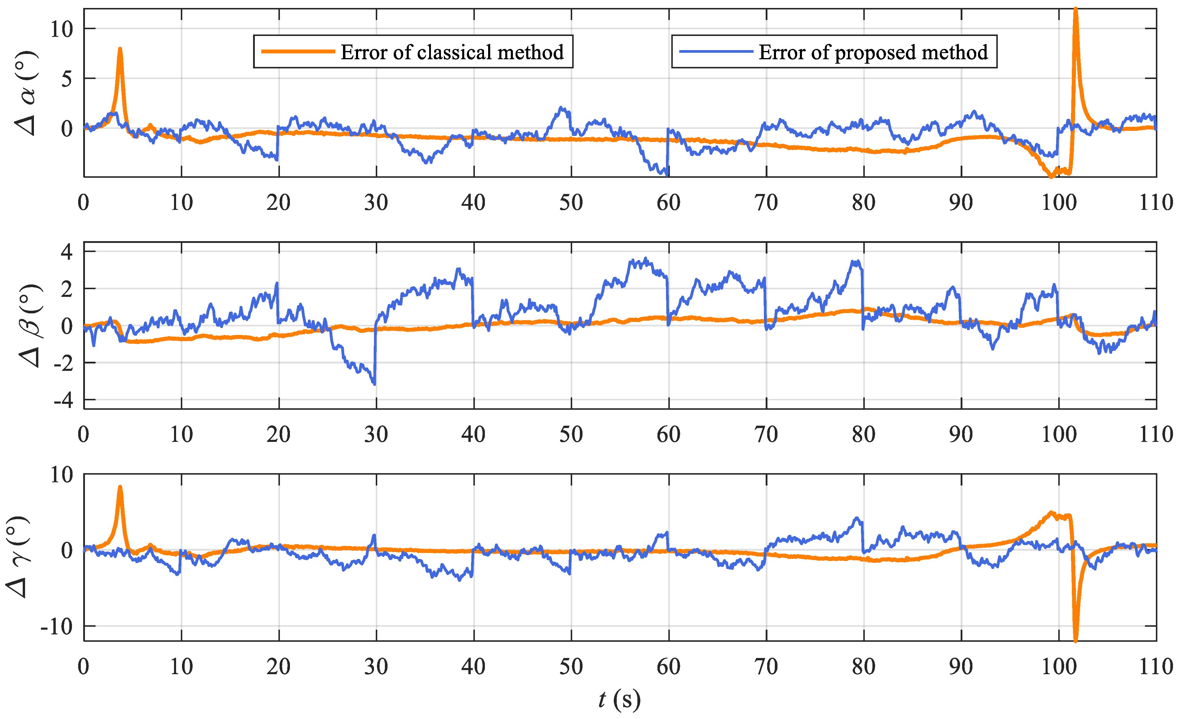
The vision/inertial fusion attitude results of the proposed method and the classical method is shown in Figure 4, which demonstrates the effectiveness of the proposed method in this experiment. The error of the classical method and proposed method are given in Figure 5, which shows the error comparison of the proposed method with the classical method.
The attitude results in Figure 4 demonstrate that the effect of the proposed method is close to the classical method in the KITTI dataset. The attitude error results in Figure 5 show the details of the proposed method, which demonstrate the effectiveness of the proposed vision/inertial integrated method and the corrected method based on the off-line attitude library.
The computational efficiency and average error of the proposed method and classical method is summarized in Table 2. Note that the average attitude error is obtained by taking the average of all three attitude angles and the processing time per frame is obtained by taking the average of all frames consuming time. As we can see from two quantitative metrics illustrated in Table 2, the average attitude error of the classical method is better than the proposed method in this case. Compared with the classical method, the processing time per frame of the proposed method is reduced by 79%.
3.3. Experiments with Urban Road Test Data
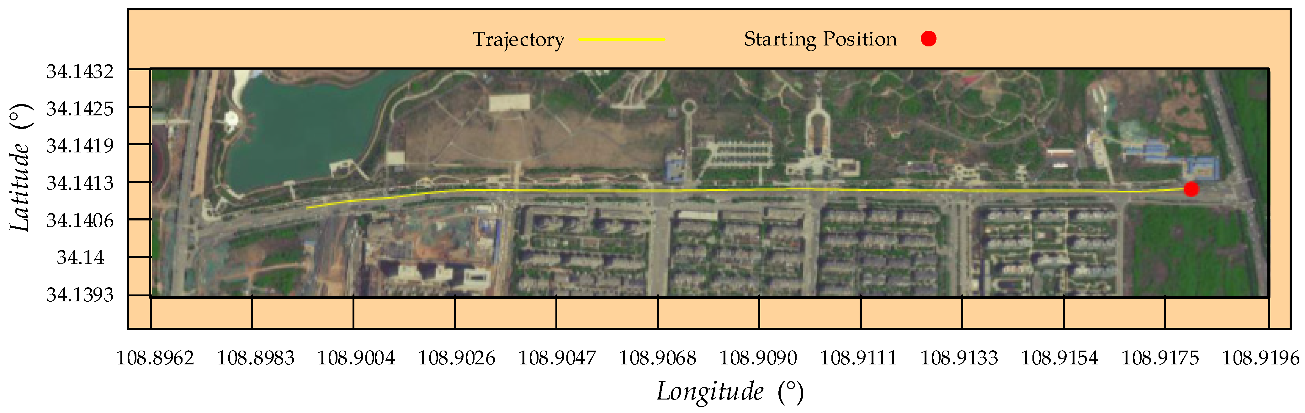
The road test experiment was conducted in Jinhu Street, Xi’an, China, which is shown in Figure 6. The vehicle velocity is about 30−40 km/h, and the trajectory of the urban road is about 1692 m.
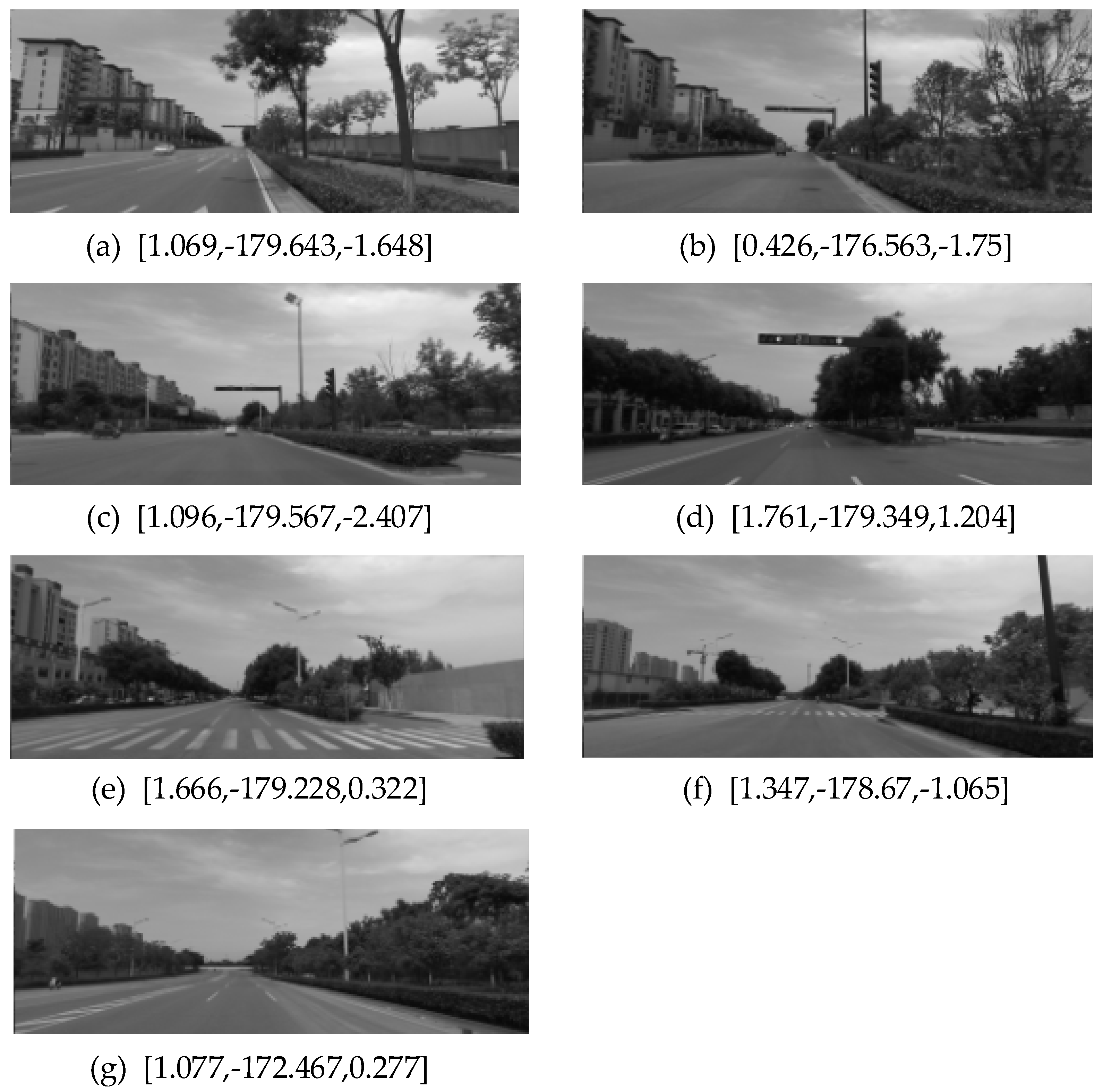
The off-line attitude library is also constructed based on the SINS/GNSS before this road test. After collecting the library data, seven locations were selected to build the library before the test, which are shown in Figure 7. The SINS used in this paper is a high-precision inertial navigation system and the attitude estimation error of the SINS/GNSS can be maintained within 0.2° during long endurance. Taking into account the attitude calibration error of SINS ant MEMS, it can be considered that the accuracy of the attitude in the attitude library is within 0.3°.
In [23], the navigation results of SINS/GNSS are used to design the ground truth of navigation because of its high precision. Thus, for verifying the accuracy of the proposed method, the tightly integrated SINS/GNSS navigation method, the same method proposed in Section 2.3, is introduced and the attitude results are used as the ground truth. The attitude estimation error by the SINS is better 0.2° per hour. Even if the GNSS fails in a short time, the attitude estimation accuracy of SINS/GNSS will not be affected. Since the attitude estimation error of the SINS/GNSS is better than 0.2°, the attitude estimation results of SINS/GNSS can be used as the ground truth.
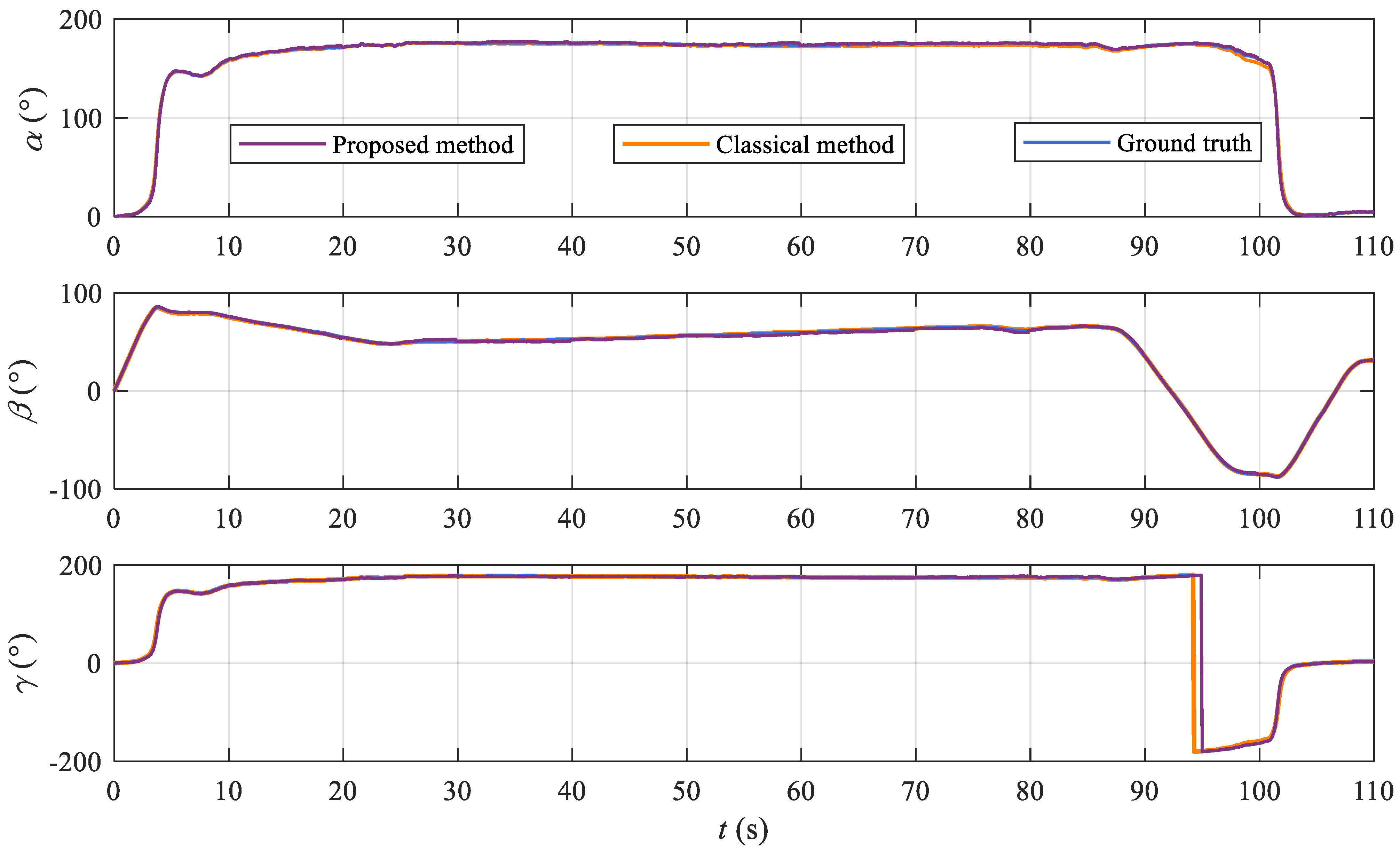
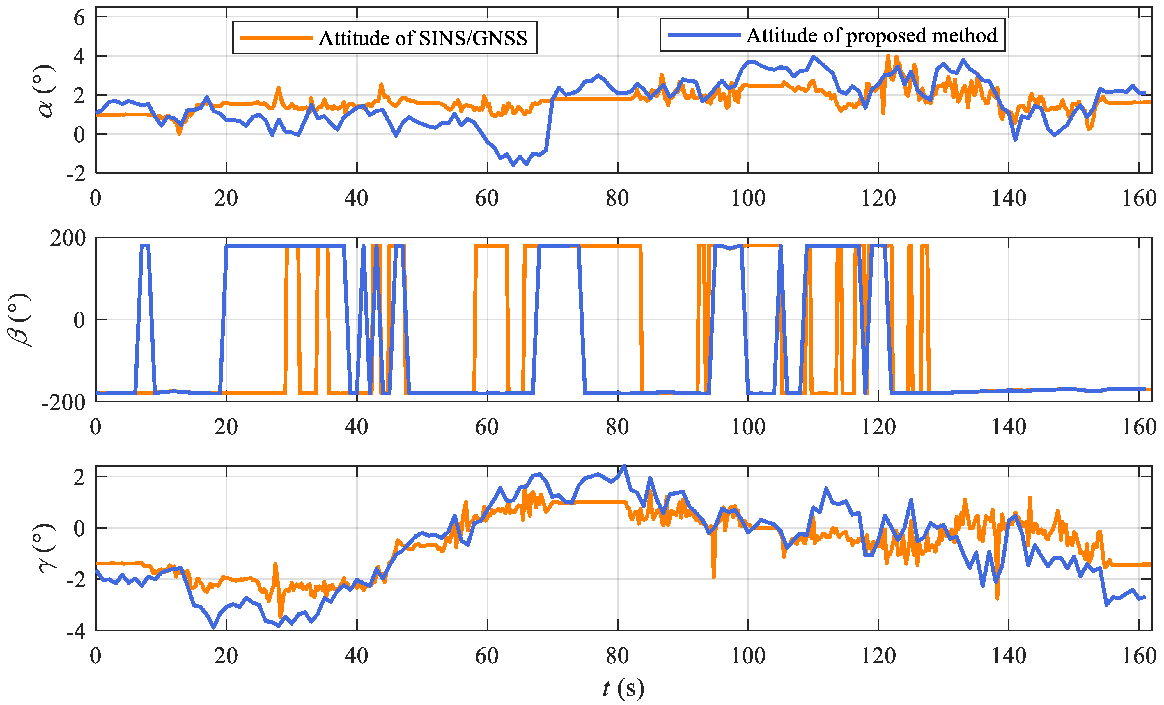
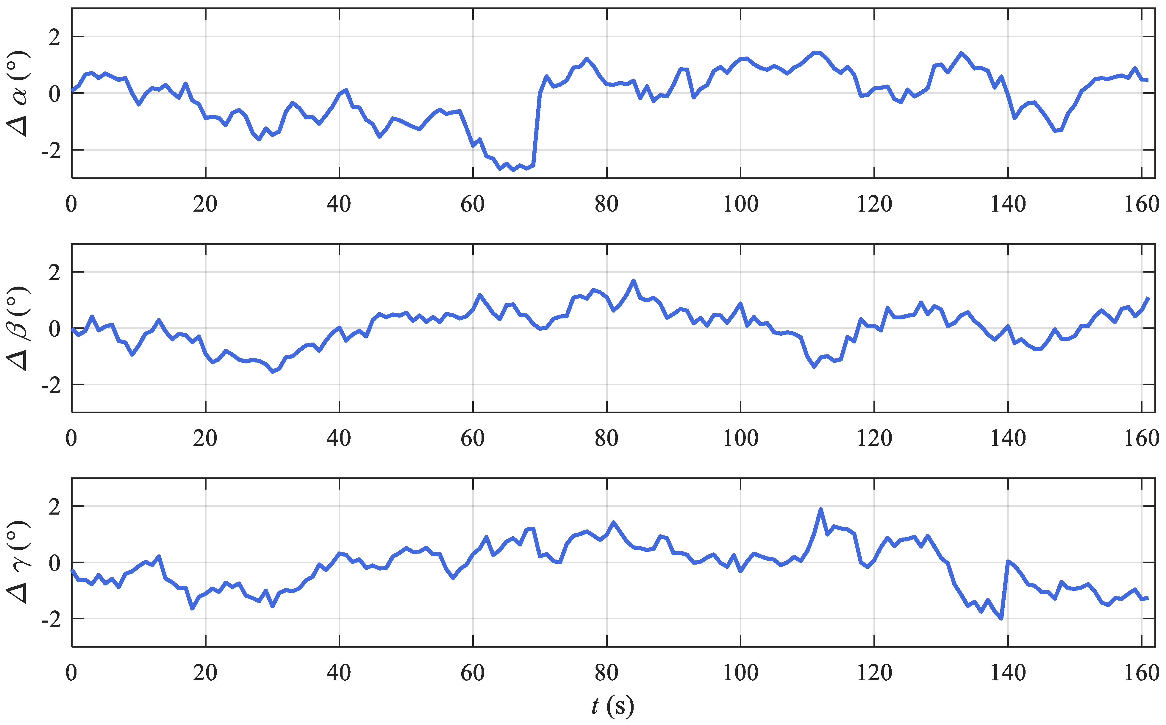
The vision/inertial fusion attitude results of the proposed method are shown in Figure 8, which demonstrates the effectiveness of the proposed method in this road test.
The attitude results in Figure 8 demonstrate that the effect of the proposed method is close to the classical method in the road test experiment. The attitude error results in Figure 9 show the details of the proposed method, which demonstrate the effectiveness of the proposed vision/inertial integrated method and the corrected method based on the off-line attitude library.
The computational efficiency and average error of the proposed method in the road test is summarized in Table 3. As we can see from two quantitative metrics illustrated in Table 3, the average attitude error of the proposed method is 1.97° in the road test and the processing time per frame of the proposed method is 24 ms.
4. Discussion
Based on the analysis of the experiment results in Section 3, the discussion of the experiment results, the proposed system, and the future work are given in Section 4.1, Section 4.2, and Section 4.3, respectively.
4.1. Discussion of the Experiment Results
As shown in Table 2, the attitude estimate accuracy of the classical method is better than the proposed method in that case. Considering that, with the endurance of UGVs, the error will inevitably accumulate with time without the loop closure. On the contrary, the attitude error of the proposed method will not accumulate. Therefore, the proposed method is more suitable for the UGVs. Most importantly, the computational efficiency of the proposed method is far superior to the classical method, which makes it possible to deploy it on industrial processors.
4.2. Discussion of the Proposed System
The purpose of this paper is to design a fast attitude estimation system for UGVs. Compared with the proposed system, using a pure vision attitude estimation module and the attitude library can also complete the task. Meanwhile, the calculation efficiency will be higher, and the accuracy will also be higher without the attitude jumping of the MEMS on bumpy roads. However, the pure visual attitude estimation module is unstable, which may track failure caused by many factors such as bumps, fast rotation, and occlusion, etc. Without the relocation, the attitude estimation will fail. In this case, fusing the vision and inertia can provide continuous attitudes for UGVs by pre-integration. That is why the MEMS/camera integration system is utilized in this paper.
4.3. Discussion of Futher Work
Fast attitude estimation makes it possible for deployment on industrial processors. In the future, we will design an attitude estimation system based on FPGA to provide high-precision and low-cost attitude estimation for UGVs.
With the development of servers and the Internet of Vehicles, all UGVs can interact with the servers in real time in the future. In this case, all UGVs will be able to upload data to the server or download data, which makes it possible for the construction and utilizing of the attitude library. In the future, we will use multi-vehicle collaboration to take a trial.
5. Conclusions
Compared with the high computational cost of the current classical vision/inertial fusion algorithm, this paper proposes a fast vision/inertial fusion system estimate attitude with high precision, which only relies on MEMS and a camera. By integrating the attitude estimated by continuous vision with the inertial pre-integration results based on optimization, the proposed system can provide high-precision attitude estimation for UGVs during long endurance. Considering that the errors of continuous vision and inertial pre-integration are cumulative, the prior information with attitude information is introduced, which are measured and labeled by off-line fusion of multi-sensors. Experimental results demonstrate the effectiveness of the proposed method. The contributions of the paper can be summarized as:
- This paper proposed a vision/inertial integration navigation system based on optimization to tackle the high computational cost of the classical method. Considering the cumulative error of the continuous vision and inertial pre-integration, the prior attitude information is introduced for correction, which is measured and labeled by an off-line fusion of multi-sensors.
- Experimental results show that in contrast with the classic method, the processing time per frame of the proposed method is reduced from 119 ms to 25 ms, which demonstrates the computational efficiency. Thus, the proposed method can tackle the high computational cost of the current vision/inertial integration method and makes it possible deploy on industrial processors.
- According to the KITTI and road test results, the proposed method is slightly inferior in accuracy. Considering that the attitude error of the proposed method will not accumulate with the endurance of UGVs, the proposed method is more suitable for UGVs in long endurance.
In short, the proposed method posse computational efficiency and accuracy for UGVs in long endurance.
Author Contributions
Conceptualization, Z.F. and C.M.; methodology, P.Y.; software, Z.F.; validation, Q.Z. and P.Y.; formal analysis, Z.F. and C.M.; investigation, Z.F.; data curation, C.M. and X.L.; writing—original draft preparation, Z.F.; writing—review and editing, C.M. and P.Y.; visualization, X.L.; supervision, Q.Z. and P.Y.; project administration, Q.Z. and P.Y.; funding acquisition, Q.Z. and P.Y. All authors have read and agreed to the published version of the manuscript.
Funding
This work was funded by the National Defense Fundamental Scientific Research of Central Military Commission (CMC), grant number 2019-JCJQ-2D-078; and by the Equipment Development Pre-research of Equipment Development Department, grant number 170441418010.
Institutional Review Board Statement
Not applicable.
Informed Consent Statement
Not applicable.
Data Availability Statement
The data supporting the findings of this study are available within the article. The raw data of SINS, MEMS, vision, and GNSS can be obtained through email with the permission of the authors.
Conflicts of Interest
The authors declare no conflict of interest.
References
- Jiang, W.; Liu, D.; Cai, B.; Rizos, C.; Wang, J.; Shangguan, W. A Fault-Tolerant Tightly Coupled GNSS/INS/OVS Integration Vehicle Navigation System Based on an FDP Algorithm. IEEE Trans. Veh. Technol. 2019, 68, 6365–6378. [Google Scholar] [CrossRef]
- Groves, P.D. Principles of GNSS, inertial, and multisensor integrated navigation systems. Ind. Robot 2013, 67, 191–192. [Google Scholar]
- Song, R.; Fang, Y. Vehicle state estimation for INS/GPS aided by sensors fusion and SCKF-based algorithm. Mech. Syst. Signal Process. 2021, 150, 107315. [Google Scholar] [CrossRef]
- Mostafa, M.; Moussa, A.; El-Sheimy, N.; Sesay, A.B. A smart hybrid vision aided inertial navigation system approach for UAVs in a GNSS denied environment. Navig. J. Inst. Navig. 2018, 65, 533–547. [Google Scholar] [CrossRef]
- Srinara, S.; Lee, C.-M.; Tsai, S.; Tsai, G.-J.; Chiang, K.-W. Performance Analysis of 3D NDT Scan Matching for Autonomous Vehicles Using INS/GNSS/3D LiDAR-SLAM Integration Scheme. 2021 IEEE Int. Symp. Inert. Sens. Syst. 2021. [Google Scholar] [CrossRef]
- Jiang, W.; Yu, Y.; Zong, K.; Cai, B.; Rizos, C.; Wang, J.; Liu, D.; Shangguan, W. A Seamless Train Positioning System Using a Lidar-Aided Hybrid Integration Methodology. IEEE Trans. Veh. Technol. 2021, 70, 6371–6384. [Google Scholar] [CrossRef]
- Zhou, P.; Guo, X.; Pei, X.; Chen, C. T-LOAM: Truncated Least Squares LiDAR-Only Odometry and Mapping in Real Time. IEEE Trans. Geosci. Remote Sens. 2021. [Google Scholar] [CrossRef]
- Fan, C.; Hu, X.; Lian, J.; Zhang, L.; He, X. Design and Calibration of a Novel Camera-Based Bio-Inspired Polarization Navigation Sensor. IEEE Sens. J. 2016, 16, 3640–3648. [Google Scholar] [CrossRef]
- He, X.; Cai, Y.; Fan, C.; He, J.; Zhang, L. Bionic Polarized Light Orientation Algorithm for Unmanned Ground Vehicle. Navig. Position. Timing 2020, 6, 231–236. [Google Scholar]
- Fan, C.; He, X.; Fan, Y.; Hu, X.; Zhang, L.; Yu, H. Integrated orientation method based on the micro-inertial and polarized vision. J. Chin. Inert. Technol. 2019, 28, 231–236. [Google Scholar]
- Servières, M.; Renaudin, V.; Dupuis, A. Visual and Visual-Inertial SLAM: State of the Art, Classification, and Experimental Benchmarking. J. Sens. 2021, 1, 1–26. [Google Scholar] [CrossRef]
- Zhai, C.; Wang, M.; Yang, Y.; Shen, K. Robust Vision-Aided Inertial Navigation System for Protection Against Ego-Motion Uncertainty of Unmanned Ground Vehicle. IEEE Trans. Ind. Electron. 2021, 68, 12462–12471. [Google Scholar] [CrossRef]
- Yu, Y.K.; Wong, K.H.; Chang, M.M.Y.; Or, S.H. Recursive Camera-Motion Estimation with the Trifocal Tensor. IEEE Trans. Syst. Man Cybern. Part B 2006, 36, 1081–1090. [Google Scholar] [CrossRef] [PubMed]
- Indelman, V.; Gurfil, P.; Rivlin, E.; Rotstein, H. Real-Time Vision-Aided Localization and Navigation Based on Three-View Geometry. IEEE Trans. Aerosp. Electron. Syst. 2012, 48, 2239–2259. [Google Scholar] [CrossRef]
- Forster, C.; Carlone, L.; Dellaert, F.; Scaramuzza, D. On-Manifold Preintegration for Real-Time Visual—Inertial Odometry. IEEE Trans. Robot. 2017, 33, 1–21. [Google Scholar] [CrossRef] [Green Version]
- Qin, T.; Li, P.; Shen, S. VINS-Mono: A Robust and Versatile Monocular Visual-Inertial State Estimator. IEEE Trans. Robot. 2018, 34, 1004–1020. [Google Scholar] [CrossRef] [Green Version]
- Campos, C.; Elvira, R.; Rodriguez, J.J.G.; Montiel, J.M.M.; Tardos, J.D. ORB-SLAM3: An Accurate Open-Source Library for Visual, Visual–Inertial, and Multimap SLAM. IEEE Trans. Robot. 2021. [Google Scholar] [CrossRef]
- Wang, J. LearnVIORB. Github. 2017. Available online: https://github.com/jingpang/LearnVIORB (accessed on 10 April 2021).
- Venator, M.; Bruns, E.; Maier, A. Robust Camera Pose Estimation for Unordered Road Scene Images in Varying Viewing Conditions. IEEE Trans. Intell. Veh. 2020, 5, 165–174. [Google Scholar] [CrossRef]
- Guerrero, J.; Murillo, A.; Sagues, C. Localization and Matching Using the Planar Trifocal Tensor with Bearing-Only Data. IEEE Trans. Robot. 2008, 24, 494–501. [Google Scholar] [CrossRef] [Green Version]
- Qin, Y.Y. Inertial Navigation; Science Press: Beijing, China, 2006. [Google Scholar]
- Mur-Artal, R.; Tardos, J.D. Visual-Inertial Monocular SLAM with Map Reuse. IEEE Robot. Autom. Lett. 2017, 2, 796–803. [Google Scholar] [CrossRef] [Green Version]
- Geiger, A.; Lenz, P.; Urtasun, R. Are we ready for autonomous driving? The KITTI vision benchmark suite. In Proceedings of the 2012 IEEE Conference on Computer Vision and Pattern Recognition, Providence, RI, USA, 16–21 June 2012; pp. 3354–3361. [Google Scholar]
Figure 1.
The working sequence of system.

Figure 2.
The working sequence of the off-line attitude library construction method.

Figure 3.
The platform of road test experiments. (a) The coordinate of the camera and the placement in the road test vehicle. (b) The coordinate of the SINS and the placement in the road test vehicle. (c) The coordinate of the MEMS and the placement in the road test vehicle. (d) The placement of the GNSS in the road test vehicle.

Figure 4.
Attitude results of the classical method, the proposed method, and ground truth.

Figure 5.
Error of the classical method and proposed with ground truth in the KITTI dataset.

Figure 6.
The trajectory of the urban road test.

Figure 7.
The attitude library of the urban road test with labeled attitude in navigation frame.

Figure 8.
Attitude results of the proposed method and ground truth.

Figure 9.
Error of the proposed method with ground truth in the road test.


Table 1.
Parameters of MEMS.
| Parameters | Unit | Value |
|---|---|---|
| Accelerometer bias | 10−3 g | |
| Accelerometer scale factor | Ppm | |
| Accelerometer installation | Arcsec | |
| Accelerometer white noise | 10−3 g/sqrt(Hz) | |
| Gyroscope bias | °/h | |
| Gyroscope scale factor | Ppm | |
| Gyroscope installation | Arcsec | |
| Gyroscope white noise | °/h/sqrt(Hz) | |
| pdate cycle | Ms | 0.005 |
Table 2.
Average attitude error and the processing time per frame of the case.
| Area | Average Velocity (km/h) | Algorithm | Average Attitude Error (°) | Processing Time per Frame (ms) |
|---|---|---|---|---|
| Highway | 75.9 | Classical | 0.79 | 119 |
| Proposed | 1.11 | 25 |
Table 3.
Average attitude error and the processing time per frame of the urban road test.
| Area | Average Velocity (km/h) | Average Error (°) | Processing Time per Frame (ms) |
|---|---|---|---|
| Urban | 30–40 | 1.97 | 24 |
Publisher’s Note: MDPI stays neutral with regard to jurisdictional claims in published maps and institutional affiliations. |
© 2021 by the authors. Licensee MDPI, Basel, Switzerland. This article is an open access article distributed under the terms and conditions of the Creative Commons Attribution (CC BY) license (https://creativecommons.org/licenses/by/4.0/).
Share and Cite
MDPI and ACS Style
Fan, Z.; Yang, P.; Mei, C.; Zhu, Q.; Luo, X. Fast Attitude Estimation System for Unmanned Ground Vehicle Based on Vision/Inertial Fusion. Machines 2021, 9, 241. https://doi.org/10.3390/machines9100241
AMA Style
Fan Z, Yang P, Mei C, Zhu Q, Luo X. Fast Attitude Estimation System for Unmanned Ground Vehicle Based on Vision/Inertial Fusion. Machines. 2021; 9(10):241. https://doi.org/10.3390/machines9100241
Chicago/Turabian StyleFan, Zhenhui, Pengxiang Yang, Chunbo Mei, Qiju Zhu, and Xiao Luo. 2021. "Fast Attitude Estimation System for Unmanned Ground Vehicle Based on Vision/Inertial Fusion" Machines 9, no. 10: 241. https://doi.org/10.3390/machines9100241
Note that from the first issue of 2016, this journal uses article numbers instead of page numbers. See further details here.