
Model Predictive Virtual Flux Control Method for Low Switching Loss Performance in Three-Phase AC/DC Pulse-width-Modulated Converters


1
School of Electrical and Electronics Engineering, Chung-Ang University, Seoul 06974, Republic of Korea
2
Department of Electrical and Computer Engineering, Mississippi State University, Starkville, MS 39762, USA
*
Author to whom correspondence should be addressed.
Machines 2024, 12(1), 66; https://doi.org/10.3390/machines12010066
Submission received: 21 December 2023
/
Revised: 11 January 2024
/
Accepted: 15 January 2024
/
Published: 16 January 2024
(This article belongs to the Special Issue Advances in Power Electronic Converters)
Abstract
:Three-phase AC/DC pulse-width-modulated (PWM) converters have been widely employed in various renewable energy systems and industrial applications, which require a high-efficiency power converter operation. This article proposes a technique to reduce switching loss in AC/DC converters by integrating a voltage vector preselection strategy to model predictive virtual flux control. The voltage vector preselection strategy preselects available voltage vectors corresponding to switching states that lead to minimum switching loss in the phase leg, which conducts the highest current. By using preselected voltage vectors, clamping intervals are generated at every fundamental period to maintain the present switching states of the power switches, resulting in the reduction in switching loss. Additionally, by using virtual flux control, the proposed approach can effectively be used under both ideal and distorted source voltage conditions. The proposed method is compared with the conventional model predictive current control and the conventional model predictive virtual flux control. Both a simulation and experiment are performed to validate the correctness and effectiveness of the proposed method, which has been found to decrease the switching loss of an AC/DC converter by up to 15% compared to conventional control schemes at a negligible increase in the input current total harmonic distortion and DC output voltage ripple.
1. Introduction
Currently, three-phase AC/DC pulse-width-modulated (PWM) converters are extensively applied in renewable energy and industrial power electronic systems, owing to their straightforward circuit configuration and capability to control sinusoidal AC source currents and DC output voltage regulations [1,2,3]. The following requirements need to be met during the high-performance operation of a three-phase AC/DC converter: a low total harmonic distortion (THD) and a well-maintained DC output voltage. To meet these abovementioned requirements, various control approaches have been extensively developed. The conventional control techniques used in AC/DC converters can be classified as voltage-oriented control (VOC) or direct power control (DPC) schemes [4,5]. Generally, in the VOC approach, internal current loops are used for reference voltage calculation, and modulation is employed to generate switching signals. In contrast, DPC focuses on directly controlling AC/DC converters by using the active and reactive power as control variables. Both methods incorporate an outer voltage loop, which is usually implemented with a proportional–integral (PI) controller, to regulate the DC output voltage.
Although previous conventional control schemes can achieve the abovementioned requirements, other control requirements, including a low switching loss, high efficiency, and proper operation under harsh conditions, are demanded in various applications. The on-state and switching power losses in AC/DC converters are relatively high when operating using pulse-width modulation (PWM), leading to lower power efficiency and a requirement for a large cooling device. Additionally, in practical applications, especially in the weak grid in renewable energy systems, AC source voltage disturbances, including unbalances and distortions, may occur. If the distorted AC source voltage conditions are not considered in the control design, the input current quality would be significantly deteriorated, and the DC output voltage might include large oscillations. Therefore, the control of three-phase AC/DC converters to achieve simultaneously high efficiency and proper operation under a distorted source voltage has become a worldwide concern. In terms of a high-efficiency target, reducing the power loss is the most popular concept. Using the soft-switching technique is a potential solution to lower the switching loss in AC/DC converters. Certain AC/DC converters employ soft-switching leverage resonant currents to charge or discharge an output capacitor of switching devices, aiming to achieve zero-voltage switching (ZVS) [6,7]. Nonetheless, these approaches necessitate the incorporation of extra passive components to establish resonant circuits. Another efficient method to reduce switching losses in an AC/DC converter is adding an offset voltage to reference voltage signals generated by the VOC strategy. This leads to the generation of discontinuous pulse-width modulations (DPWMs) [8,9,10]. By linking a phase leg of the AC/DC converter to a positive or negative DC-rail, the reduction in switching loss can be achieved. However, DPWMs can deteriorate the performance of an AC/DC converter, which is attributable to the increasing harmonic distortion in input currents. Meanwhile, the proper operation of an AC/DC converter under distorted source voltage conditions is extensively investigated in [11,12,13]. However, the developed approaches focus on only one aspect of high efficiency or proper operation under a distorted source voltage condition.
In recent years, model predictive control (MPC), as a novel high-performance control method, has been widely employed to power electronic devices, which shows significant advantages in both disturbance rejection capability and dynamic performance [14,15]. Recently, MPC has been improved by applying a neutral network to attenuate the inherent issues of system uncertainties, approximation error, and external disturbances [16,17]. In terms of MPC approaches for AC/DC converters, the developed techniques include model predictive current control (MPCC) [18], model predictive virtual flux control (MPVFC) [19,20], model predictive direct power control (MPDPC) [21], and model predictive virtual flux direct power control (MPVFDPC) [22]. These approaches rely on the prediction concept, but each employs distinct cost functions, leading to various performances, especially in situations where AC/DC converters are operating under distorted source voltage conditions. Thanks to the characteristics of containing several control objectives simultaneously in a predesigned cost function, MPC approaches can reduce the switching loss of an AC/DC converter by including the term related to the number of switching actions or power loss [23,24]. However, these approaches require a proper weighting factor to guarantee the control variables. Other MPC schemes use optimal switching sequences or preselected switching states to reduce the switching loss of AC/DC converters [25,26]. Regarding the operation of AC/DC converters under distorted source voltage conditions, the MPVFC in [19] can mitigate the degradation of input currents, whereas a neutral network-based virtual flux estimator is proposed in [20]. A new definition of instantaneous reactive power in the predefined cost function is developed in [27] to cope with the problem of highly distorted input currents under distorted source voltage conditions. The study in [28] adds a cascaded delayed signal cancellation block to obtain the fundamental rectifier voltages in the virtual flux-based grid voltage sensorless method. Hence, this method can operate under unbalanced and distorted source voltage conditions. Apparently, limited research-based MPC can achieve both high efficiency and proper operation under distorted source voltage conditions for AC/DC converters.
Following a previous analysis, a control method, which can simultaneously achieve high efficiency and proper operation under distorted source voltage conditions in addition to the base requirements of a sinusoidal, low THD input current and a well-maintained DC output voltage, is crucial following the demand for renewable energy systems and industrial applications. In this article, a voltage vector preselection strategy is proposed to be integrated into the MPVFC approach in [19] to achieve a low switching loss, high efficiency, and proper operation under distorted source voltage conditions. The proposed technique employs a voltage vector preselection strategy instead of using a cost function with multiple terms to reduce the switching loss of three-phase AC/DC converters, resulting in improved efficiency. The voltage vector preselection strategy is based on the identification of the phase leg that conducts the highest current to preselect four voltage vectors corresponding to switching states that result in minimum switching loss to evaluate in the next sampling instant. The reference AC/DC converter input voltage and measured input current will be used to identify the phase leg that conducts the highest current, resulting in the highest switching loss. By evaluating the proper voltage vectors at every sampling instant to predict the future behavior of the virtual flux, clamping intervals will be generated, which are placed around the peak current in each phase leg. Thus, the switching state of that phase leg will be unchanged, resulting in a decrease in the switching loss. Simultaneously, the use of virtual flux as a control variable in the MPC approach will guarantee sinusoidal input currents and a low DC output voltage ripple under distorted source voltage conditions. The contributions and advantages of the proposed technique include the following:
- -
- A power loss reduction is achieved without deteriorating the input current’s harmonic distortion and the DC output’s voltage ripple.
- -
- The sinusoidal input current is maintained under distorted source voltage conditions thanks to the use of virtual flux.
- -
- The proposed technique allows for the straightforward implementation of the voltage vector preselection strategy even in practical systems.
- -
- The requirements of additional terms in the cost function and extra hardware to implement the proposed approach are eliminated.
The technical challenge of the proposed method for AC/DC converters is the accuracy of measured input currents. Because the voltage vector preselection strategy employs both predicted reference AC/DC converter input voltages and measured input currents to determine the clamping phase, the measured input currents should be accurate with low noise to guarantee the accuracy of the clamping phase and the magnitude of clamping intervals that correspond to the highest absolute input current. Thus, the selection and tuning of current sensors should be implemented carefully. Additionally, the number of sensors might be a burden of the proposed control technique, and sensorless operation should be considered in the future work.
The simulation and experimental results will be presented to demonstrate the correctness and effectiveness of the proposed method under both ideal and distorted source voltage conditions. The proposed technique’s performance will be compared to conventional MPCC [18] and conventional MPVFC [19], where all approaches are applied to two-level three-phase AC/DC converters.
The rest of this article is arranged as follows: Section 2 briefly explains the principle of the conventional MPCC and conventional MPVFC methods. Section 3 presents the proposed MPVFC with a voltage vector preselection strategy to increase the efficiency of AC/DC converters in both ideal and distorted source voltage conditions. Section 4 covers the simulation and experimental results, and it presents a performance evaluation under different situations to validate the proposed approach. Section 5 concludes this article.
2. Conventional Model Predictive Control Approaches for AC/DC Converter
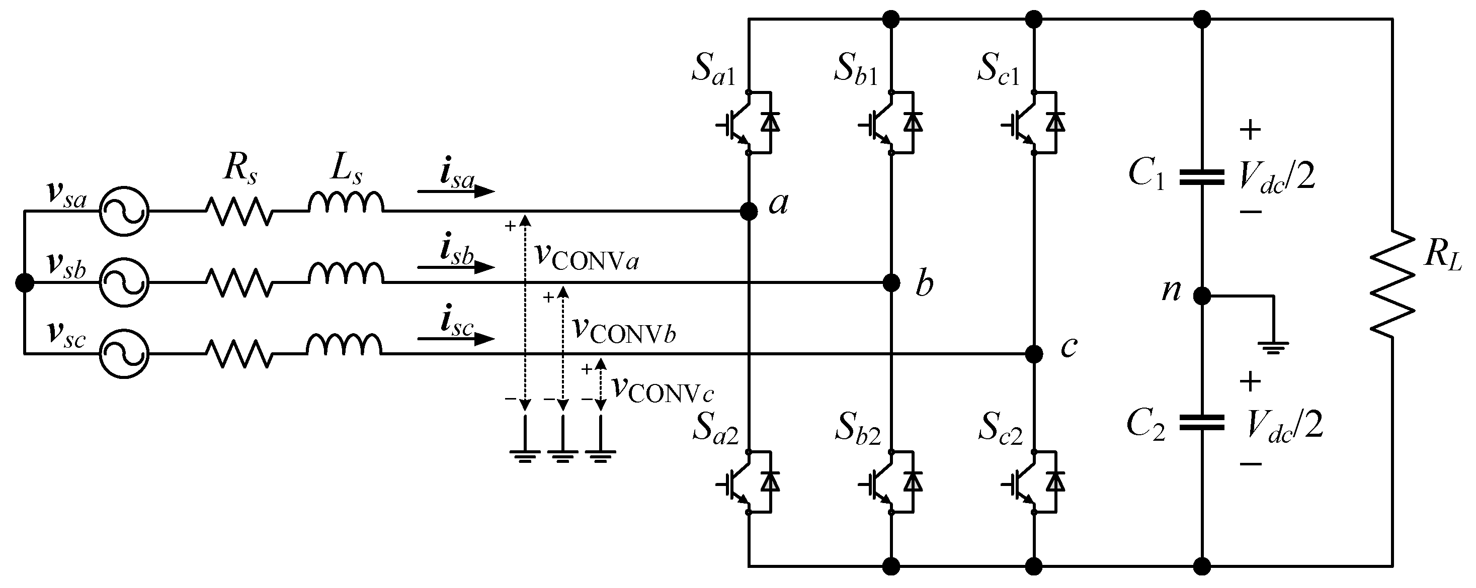
The structure of the three-phase AC/DC converter is shown in Figure 1. In the figure, , , and are the AC source voltages; and are the filter resistance and inductance; , , and are the input currents; , , and are the AC/DC converter input voltages; and are the DC output capacitances; is the DC load resistance; and is the DC output voltage. A two-level three-phase AC/DC converter is composed of six power switches, denoted by . The switching state takes a value of zero when the power switch is turned off, and the value is unity when the power switch is turned on. The corresponding AC/DC converter input voltage of each phase can be arbitrarily configured to connect with (if ) or 0 V (if ). Therefore, there are eight different switching states corresponding to eight voltage vectors in the two-level three-phase AC/DC converter, as presented in Table 1.
Based on the transformation principle of the two-phase fixed coordinate system, the mathematical model of the three-phase AC/DC converter on the axis is obtained as follows:
where , , and are the components of AC source voltage, input current, and AC/DC converter input voltage, respectively.
The MPCC algorithm aims to tackle the operation constraints in the AC/DC converter by focusing on tracking the input current. The future behavior of the input current is yielded by rearranging (1) and using the forward Euler method as
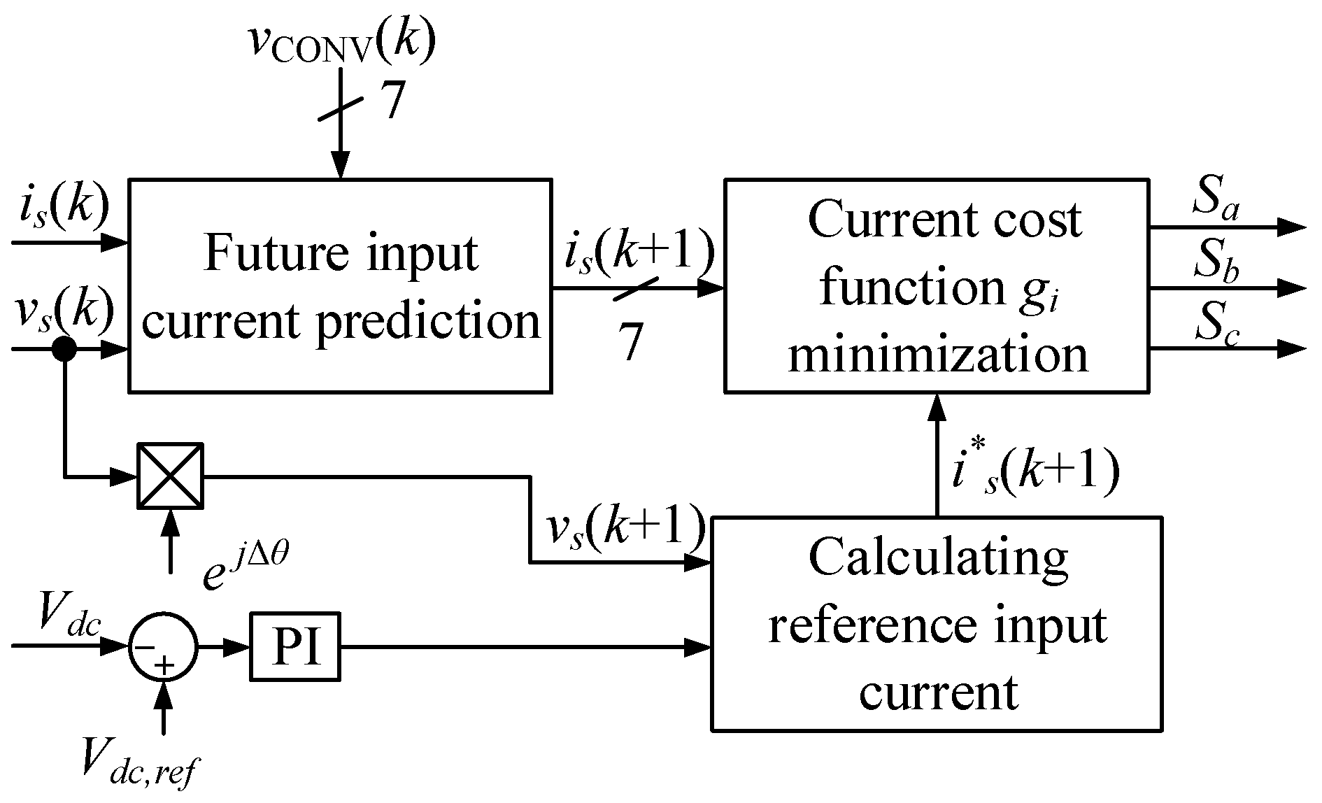
Figure 2 illustrates the block diagram of conventional MPCC [18]. The regulation of the DC output voltage and the determination of the reference input current amplitude are achieved through the utilization of a PI controller. The reference current is computed by multiplying the output of the PI controller by the AC source voltage waveform. The sampling frequency is normally considerably greater than the fundamental frequency of the AC source voltage; thus, . If the sampling frequency is not high enough, the precise determination of the AC source voltage at the sampling instant can be calculated as
where is the angle advance of the AC source voltage in one sampling instant, and is the angular frequency of the AC source voltage.
In the conventional MPCC approach, by discretizing the AC/DC converter model, as carried out in (2), and applying the measured input current and AC source voltage as well as seven possible voltage vectors that can be selected in the next sampling period, seven possible future input current vectors will be generated. The future input current vectors are then compared with the corresponding reference input current . A cost function considering the absolute difference between the future input current and the corresponding reference input current will be used to determine the optimal switching state, minimizing the cost function value as
Although the conventional MPCC approach effectively controls the input currents of the AC/DC converter in normal conditions, where AC source voltages are perfectly balanced and sinusoidal, its performance may decline considerably, potentially resulting in a loss of control, when faced with a distorted AC source voltage. The reason for this is the use of distorted AC source voltage directly. To address this issue, virtual flux is employed as an alternative control parameter. In this study, the conventional MPVFC in [19] will be adopted. The virtual flux concept assumes that the AC source voltage and the line filter are related to a virtual AC motor. Making an analogy with AC motors, and represent, respectively, the stator resistance and stator inductance, and the AC source voltages stand for the motor’s electromotive force. Hence, the integration of the AC source voltage vectors yields the virtual flux vector as
In [19], the integration of the MPVFC approach is accomplished by incorporating a low-pass filter, along with a compensation gain . This configuration, illustrated in Figure 3, is employed to remove unwanted DC components. Figure 3 illustrates the block diagram of the conventional MPFVC approach. According to (5), the future virtual flux vector can be described in the discrete time domain as follows:
The future virtual flux in the AC source voltage at the sampling instant can be obtained by integrating the AC source voltage vectors in the discrete time domain as follows:
Similar to (7), the future virtual flux of the AC/DC converter input voltage at the sampling instant can be calculated as
Following the definition of virtual flux and (6), the future virtual flux of the AC/DC converter input voltage can be deduced from (8) as follows:
To mitigate the delay impact while implementing the MPC schemes in a practical system, a delay compensation algorithm [29] is applied to obtain the future virtual flux of the AC/DC converter input voltage at the sampling period.
Due to the use of an AC/DC converter input voltage vector , as seen in (10), seven possible future virtual fluxes of the AC/DC converter input voltage will be generated. These possibilities will be compared with the reference value of the future virtual flux of the AC/DC converter input voltage vector to find out the optimal switching state. The future reference virtual flux vector can be derived from (6) by using the future reference input current instead of the measured input current.
The virtual flux cost function associated with the future virtual flux of the AC/DC converter input voltage and corresponding future reference virtual fluxes will be constructed as
3. Proposed High Efficiency Model Predictive Virtual Flux Control with Voltage Vector Preselection Strategy for AC/DC Converter
In order to achieve high efficiency operation in AC/DC converters, the proposed voltage vector preselection algorithm is integrated into the MPVFC approach. The proposed control scheme aims at reducing the switching loss in AC/DC converters and guaranteeing the output performance, even in distorted AC source voltage conditions. The magnitude of the input current during the switching instants determines the instantaneous switching losses in the AC/DC converter switches. Thus, it is reasonable to avoid changing the current state of the switches conducting the largest input current. Hence, different from the conventional MPCC and MPVFC approaches, where all seven voltage vectors are used to generate future input currents or future virtual fluxes of AC/DC converter input voltages, the proposed MPVFC with the voltage vector preselection strategy uses only four voltage vectors, which leads to minimum switching loss in the next sampling instant. The four voltage vectors will be preselected at every single sampling instant to generate possibilities of virtual fluxes of AC/DC converter input voltages in the next sampling instant. The selection of these voltage vectors is based on the principle that the phase exposed to the largest input current during the next sampling instant will be clamped to the positive or negative DC-link, which means that the corresponding switching state of this phase will be maintained to reduce the switching loss.
In order to preselect the voltage vectors, the future reference AC/DC converter input voltage and input current will be employed. The future reference AC/DC converter input voltage vector is derived from (2) by replacing the measured input current by the reference input current as follows:
Then, the future reference AC/DC converter input voltage in the frame will be transformed to frame components and sorted depending on their instantaneous magnitude as follows:
First, based on the sorted future reference AC/DC converter input voltage, the voltage vector preselection algorithm determines which phase may be clamped. The phase that may be clamped is the phase that corresponds to or . Meanwhile, the prohibitive phase avoiding clamping is the phase that corresponds to to guarantee that the AC/DC converter operates within the linear modulation range. Then, by using the measured input currents, the phase input current having the highest absolute magnitude is determined. This phase leg will be selected as the clamping phase to avoid changing the switching state during the next sampling instant. For instance, if phase- reference AC/DC converter input voltage is determined as the , phase- will be considered to be clamped in the next sampling instant. The absolute value of the input current in phase- will be compared to the absolute value of the input current corresponding to . If the absolute value of the input current in phase- is higher than the absolute value of the input current corresponding to , four voltage vectors that lead to maintaining the present switching state of phase- will be preselected for evaluation in the next sampling instant. On the other hand, four other voltage vectors will be preselected if the absolute value of the input current in phase- is lower than the absolute value of the input current corresponding to . By employing only four preselected voltage vectors, the proposed MPVFC with the voltage vector preselection strategy can maintain the switching states of phase legs during multiple clamped intervals situated around the peak value of the corresponding input current. As a result, the switching loss in phase legs will be decreased, leading to the improved efficiency of AC/DC converters. Figure 4 illustrates the flowchart of voltage vector preselection strategy.
Table 2 displays the availability of preselected voltage vectors following future reference AC/DC converter input voltages and corresponding input currents. Because the phase difference between the reference AC/DC converter input voltages is , and the clamping intervals are evenly distributed among the three phase legs of the AC/DC converter, the total clamping interval of each phase in one fundamental period will be .
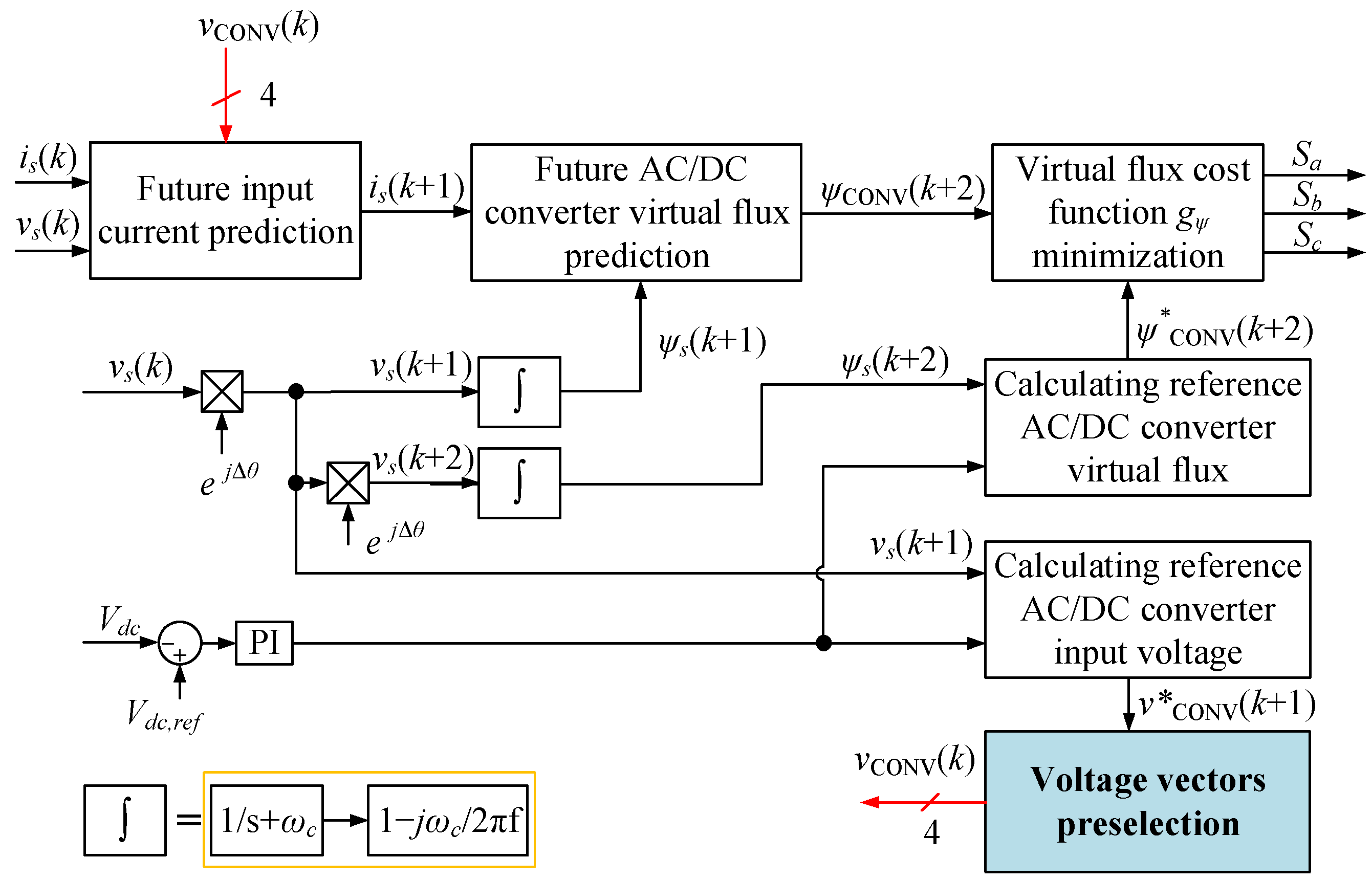
Figure 5 depicts the block diagram of the proposed MPVFC with the voltage vector preselection strategy. The principle of generating future virtual flux is similar to conventional MPVFC in Figure 3, where the measured source voltages and input currents are employed. Meanwhile, the DC output voltage is regulated by a PI controller, where the output of this PI controller is used to calculate the reference virtual flux and the reference AC/DC converter input voltage. Then, the future virtual flux and reference virtual flux are evaluated using the cost function to produce switching patterns. It can be observed that the difference between the conventional MPVFC and the proposed approach is the voltage vector preselection block, as depicted in Figure 5.
4. Evaluation Results
A simulation using a PSIM program and experiments are conducted to verify the validity and performance of the proposed MPVFC with the voltage vector preselection strategy. The performance between the proposed method and conventional MPCC and MPVFC approaches is analyzed and evaluated. The AC/DC converter in Figure 1 is designed with the listed parameters in Table 3. The input filter is employed in this study due to it being relatively straightforward to design and implement. With fewer components, the filter is generally more cost-effective compared to more complex configurations of or filters. The selection of a filter inductor and capacitor is followed by the design guide for the TIDM-1000 rectifier from Texas Instrument and available equipment in the laboratory [30]. In the MPC technique, the switching state of the converter can be changed once in each sampling instant. Consequently, the switching frequency is limited to half of the sampling frequency (). However, the switching states might be unchanged in each sampling instant, resulting in the average switching frequency always being less than . Additionally, the proposed approach can maintain the switching state of phase legs during multiple clamped intervals situated around the peak value of the corresponding input current. Therefore, the results show that the average switching ferequency is concentrated between and , which is equivalent to 4 kHz to 5 kHz. The value of the inductor is determined by the following parameters, including the DC-link output voltage, the switching frequency, and the current ripple needed. The value of the input inductor is calculated as follows:
where is the maximum ripple of the input current. The PI gains are selected to achieve desirable performance in both steady-state and transient-state operations.
Both a simulation and experiment are conducted under two cases of AC source voltages as follows:
- Case 1. This is an ideal condition where the AC source voltages are perfectly balanced and sinusoidal.
- Case 2. This is a distorted source voltage condition where the fifth harmonic component is injected to phase-a AC source voltage.
4.1. Simulation Results Analysis
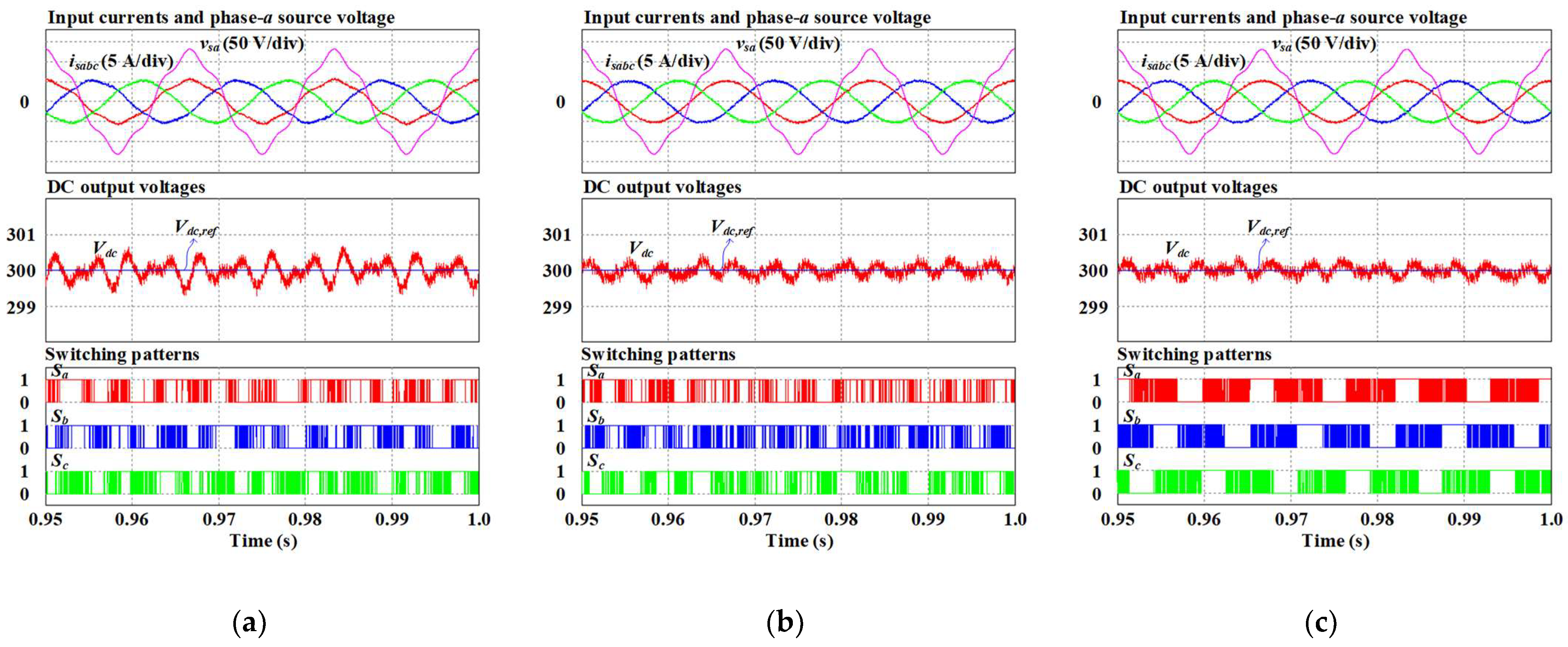
Figure 6 shows the simulation results in case 1. In these figures, the three-phase input currents, phase- AC source voltage, DC output voltage, corresponding reference, and switching signals are presented. The input current waveforms obtained by the conventional MPCC, conventional MPVFC, and proposed MPVFC approaches are sinusoidal and balanced. The phase- input current is in phase with the corresponding AC source voltage, and there is no distortion in the input currents. The DC output voltages produced by both three approaches accurately follow the corresponding reference of 300 V. In Figure 6c, the switching signals obtained by the proposed MPVFC method contain clamping intervals during one-third of the fundamental period. These clamping intervals situate around the peaks of the input currents, as expected.
Figure 7 shows the simulation results in case 2, where the fifth harmonic component with a magnitude of a 10% peak value of the AC source voltage is injected to the phase- AC source voltage. As shown in Figure 7a, the phase- input current obtained by conventional MPCC is distorted. Meanwhile, thanks to the use of virtual flux, the input currents in conventional MPVFC and proposed MPVFC approaches are sinusoidal and balanced without any distortion. The unity power factor operation is maintained under distorted source voltage conditions. The DC output voltage obtained by three control schemes keeps correctly tracking the corresponding reference but with a higher ripple, especially in conventional MPCC. Additionally, In Figure 6c, the switching signals obtained by the proposed MPVFC method contain clamping intervals during one-third of the fundamental period. These clamping intervals situate properly around the peak of input currents, even in distorted source voltage conditions.
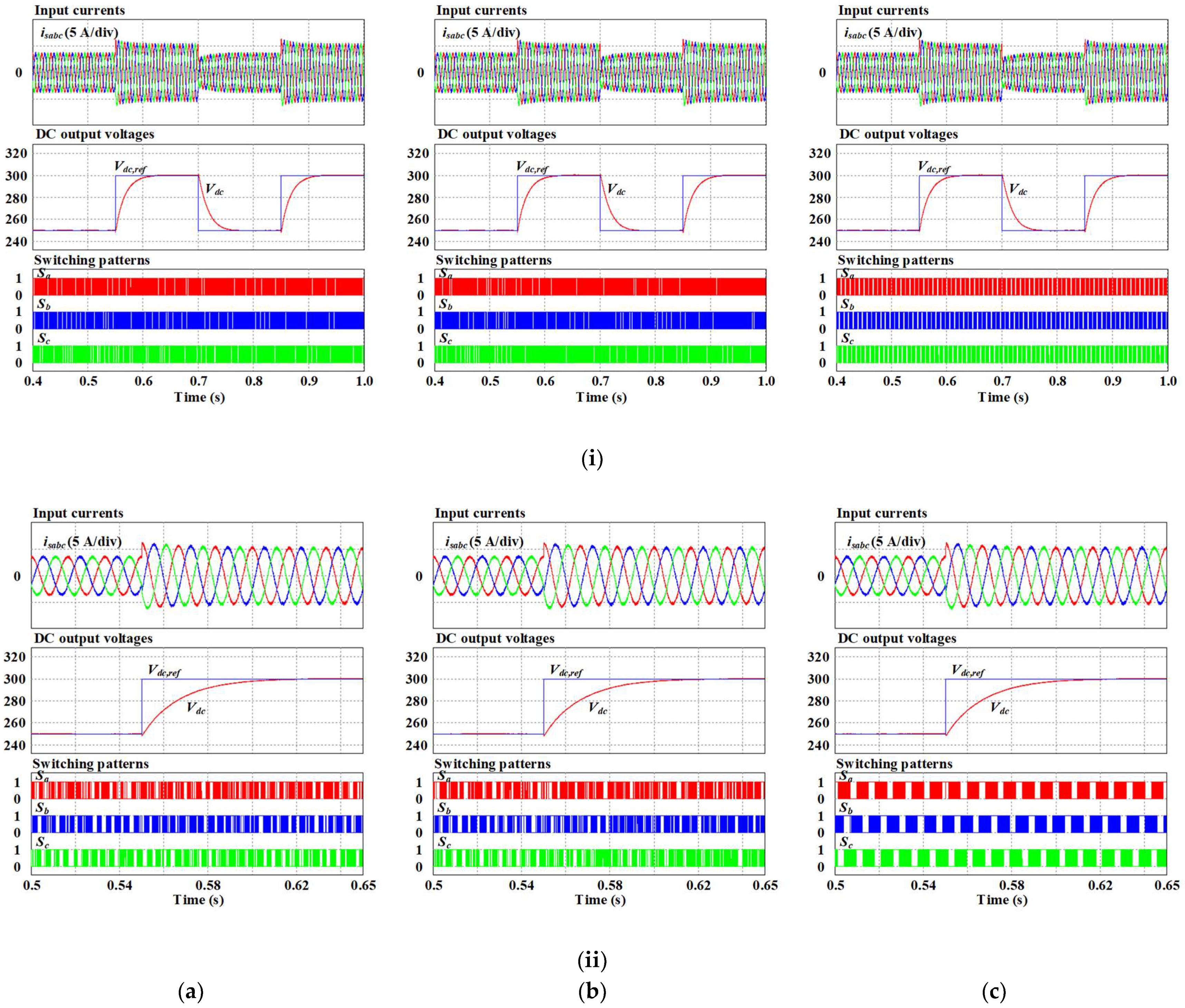
Figure 8a–c illustrate the performance of an AC/DC converter obtained under a periodical change in the reference DC output voltage obtained by conventional MPCC and MPVFC and proposed MPVFC methods. In Figure 8, the reference DC output voltage varies between 250 and 300 V. As can be seen, the magnitude of input current obtained by three control schemes changes correspondingly to the variation in the reference DC output voltage. The DC output voltage correctly tracks its reference with negligible overshoot during the dynamic response. As can be seen, the proposed MPVFC method has a similar dynamic performance as the two conventional approaches. Additionally, the proposed MPVFC with the voltage vector preselection strategy correctly generates clamping interval under the change in the DC reference output voltage, which can be observed through the switching signals.
In Figure 9, the magnitude of the load resistance is periodically changed between 50 Ω and 100 Ω. The input currents obtained by both three approaches change according to the change in the load resistance. The DC output voltage is kept at a reference value of 300 V but with a high overshoot during the dynamic response. As can be seen, the proposed MPVFC method has a similar dynamic performance as the two conventional approaches. The switching signals of three-phase legs correctly contain total clamping intervals of one-third of the fundamental period, even during the dynamic response.
From the simulation results, it can be concluded that the proposed MPVFC operates correctly at both the steady state and transient state.
4.2. Experimental Results
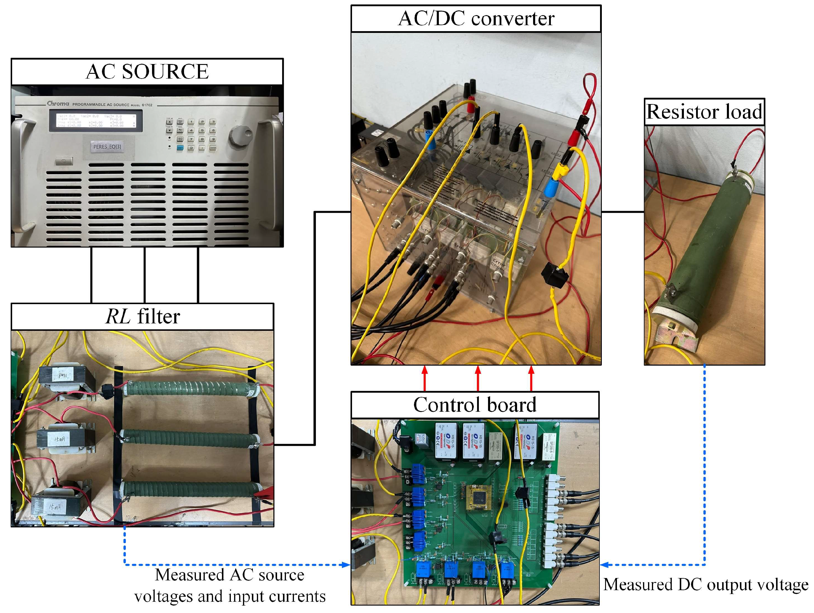
Figure 10 shows the experimental prototype of an AC/DC converter system. For an AC source voltage, a Chroma programmable AC source has been used to emulate the three-phase voltage in both of the cases. In addition, the three-phase legs of the AC/DC converter were built by three bidirectional IGBT SKM50GB123D switches. The controller was implemented by using TI DSP TMS320F28335.
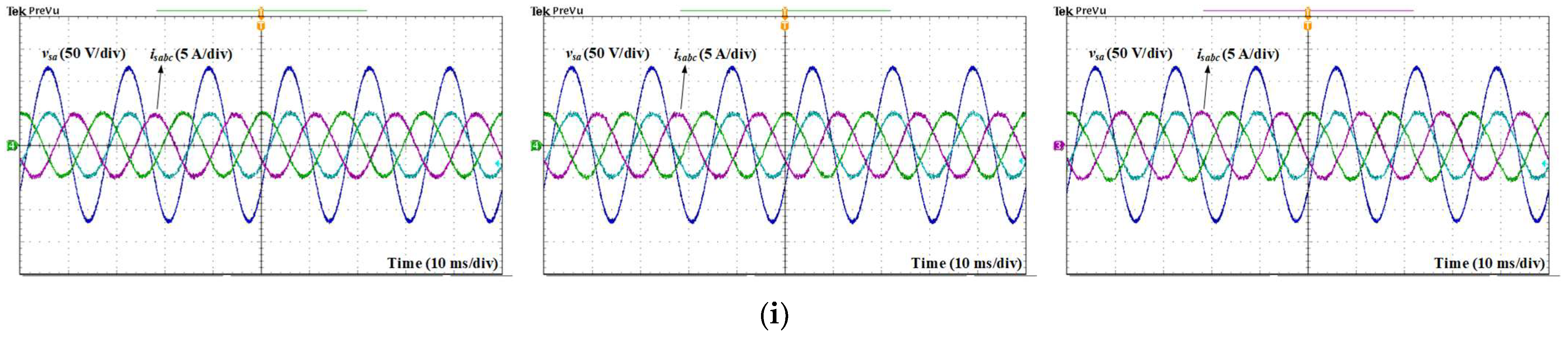
Figure 11a–c display the experimental waveforms obtained by conventional MPCC, conventional MPVFC, and the proposed MPVFC approach with a voltage vector preselection strategy. Similar to the simulation results, the three control schemes exhibit both sinusoidal and balanced input currents under ideal conditions. The input current is in phase with the AC source voltage, demonstrating the unity power factor operation of the AC/DC converter. As can be seen from the FFT analysis results of the input current, the input current total harmonic distortion (THD) values obtained with the conventional MPCC and MPCVFC methods are 3.57% and 3.67%, respectively. Meanwhile, the input current THD is 4.14% when the AC/DC converter is controlled by the proposed MPFVC approach. It can be seen that the THD of the proposed MPVFC method is a little higher than that of the conventional control schemes because of the clamping intervals. The DC output voltage generated by the three control schemes correctly follows the corresponding reference of 300 V. As shown in Figure 11c, the switching signals of three phase legs correctly contain a total clamping interval of one-third of the fundamental period. These clamping intervals lead to the reduction in switching loss in AC/DC converters controlled by the proposed MPVFC with the voltage vector preselection strategy.
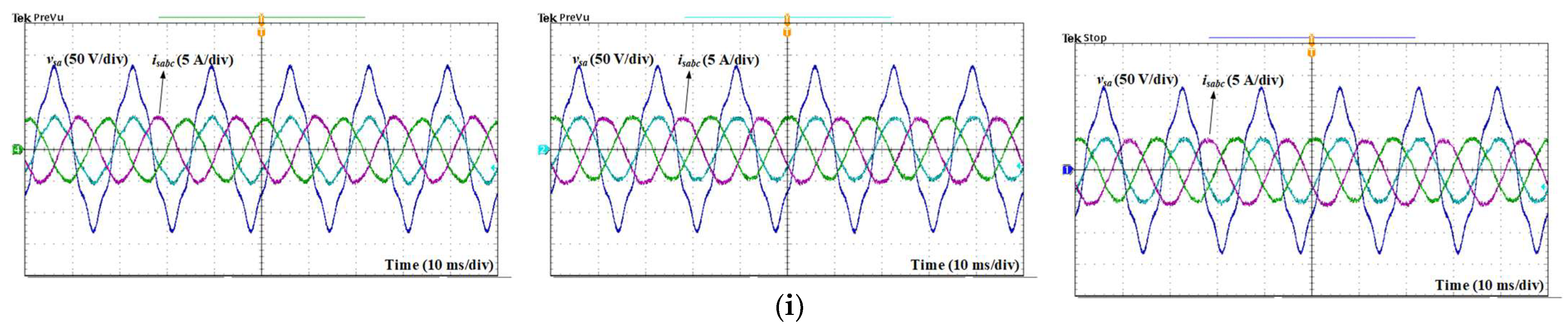
Figure 12 illustrates the experimental results in case 2, where the fifth harmonic component with a magnitude of 10% of the peak value of the AC source voltage is injected to the phase- AC source voltage. In Figure 12a, it can be observed that the input currents are distorted. Meanwhile, thanks to the use of virtual flux control, the input currents obtained by the conventional MPVFC and proposed MPVFC methods have sinusoidal waveforms. From the FFT analysis of the input current in Figure 12a, the dominant fifth harmonic component is clearly shown, which leads to a significantly high THD of 6.61%. Meanwhile, the dominant fifth harmonic component in input currents is eliminated apparently by employing the conventional MPVFC and proposed MPVFC approaches, as shown in Figure 12b and Figure 12c, respectively. The input current THD with the proposed MPVFC approach is lower than that of the conventional MPCC approach but still higher than conventional MPVFC due to the clamping intervals in the proposed MPVFC approach. Under distorted source voltage conditions, the DC output voltage is maintained accurately at the desired value of 300 V with all three approaches. In Figure 12c, the obtained switching signal waveforms indicate the proper operation of the proposed MPVFC approach under distorted source voltage conditions, where the generated clamping intervals are correct in one-third of the fundamental period and located around the peak input currents.
Figure 13a–c illustrate the performance of the AC/DC converter under the step-change of the reference DC output voltage from 250 V to 300 V obtained by the conventional MPCC, conventional MPVFC, and proposed MPVFC methods. As can be seen, the magnitude of the phase- input current obtained by the three control schemes changes correspondingly to the variation in the reference DC output voltage. The DC output voltage correctly tracks its reference with a negligible overshoot during the dynamic response. The proposed MPVFC method has a similar dynamic performance as the two conventional approaches but with a marginally higher overshoot compared to the conventional MPCC approach. Additionally, the proposed MPVFC approach with the voltage vector preselection strategy correctly generates a clamping interval under the change in the DC reference output voltage, which can be observed through the switching signals.
The comparable results obtained by both the simulation and experiment under ideal and distorted source voltage conditions verify the correctness of the proposed MPVFC approach with the voltage vector preselection strategy.
In terms of MPC approaches, concerns related to robustness against parametric uncertainties and model inaccuracies should be investigated. To assess the performance of the proposed MPVFC method under such conditions, relevant experiments are carried out. Figure 14 demonstrates the experimental waveforms under ideal conditions with the situation in which the model inductance varies by 50% from the actual value. It can be seen that in Figure 14a, the phase- input current is distorted, and there is a small phase difference between the input current and AC source voltage. Meanwhile, the DC output voltage and switching signal are well maintained. Figure 14b illustrates the waveforms when the model inductance exists at a +50% deviation from the actual value. It can be seen that all waveforms of the input current, DC output voltage, and switching signal are well regulated as in normal conditions. Similar outcomes are exhibited by the proposed MPVFC method under distorted source voltage conditions in the situation when the model inductance varies by 50% from the actual value, as depicted in Figure 15. When the model inductance exists at a −50% deviation from the actual value, the input current waveform is not perfectly sinusoidal due to some distortions. Meanwhile, even under distorted source voltage conditions with a situation in which the model inductance is 50% higher than the actual inductance, all waveforms of the input current, DC output voltage, and switching signal are well maintained. Therefore, it can be concluded that the proposed MPFVC approach with the voltage vector preselection strategy shows correct operation against filter inductance uncertainties.
4.3. Performance Evaluation
The performance among the conventional MPCC, conventional MPVFC, and proposed MPVFC methods is further evaluated under various conditions. The obtained performance aspects, including the input current average THD, the DC output voltage peak-to-peak ripple value, total switching loss, and efficiency, are investigated. Regarding the loss of power switches in the AC/DC converter, the conduction loss and switching loss are calculated following the application note for IGBT power loss calculation using the datasheet parameters of IGBT SKM75GB07E3 [31,32]. The basic parameters of IGBT SKM75GB07E3 are listed in Table 4. In this study, the converter efficiency is calculated by employing the calculated input power from the AC source and calculating the total loss of power switches in the AC/DC converter as described in the following equation:
The choice of the sampling period significantly influences the control performance and switching frequency in the MPC approach. A small sampling period will result in a high performance in the system, but power switches will be operated with a high switching frequency. On the other hand, the performance of the system is lowered with a large sampling period. Figure 16a–d show the comparison between the three approaches under the change in the sampling period. Figure 16a,b show that the performance of the AC/DC converter is lowered along with the rise in the sampling period. Additionally, the proposed MPVFC approach exhibits a higher input current THD and DC output voltage peak-to-peak ripple than conventional MPCC and conventional MPVFC methods, as shown in Figure 16a,b. However, the difference is negligible. The total switching loss in the proposed MPVFC method is remarkably lower than that of the conventional MPCC and conventional MPVFC approaches. The reduction in the total switching loss can be up to 15% compared to that of conventional control schemes, as shown in Figure 16c. Due to the significant reduction in switching loss, the proposed MPVFC achieves the highest efficiency, as shown in Figure 16d.
Figure 17a–d show a comparison between the three approaches under the change in the magnitude of the injected fifth harmonic component. The zero magnitude indicates the ideal condition. As shown in Figure 17a, the input current average THD of the conventional MPCC approach increases dramatically when the magnitude of the injected fifth harmonic component rises. Meanwhile, due to the MPVFC control scheme, the fifth harmonic component in input currents of AC/DC converters can be eliminated, the average THD of input currents acquired by the conventional MPVFC and proposed MPVFC approaches increases marginally coupled with the increase in the amplitude of the injected fifth harmonic component, as shown in Figure 17a. The DC output voltage peak-to-peak ripple of the conventional MPCC approach will be the highest under the variation in the magnitude of the injected fifth harmonic component. In terms of the total switching loss in Figure 17c, thanks to the generated clamping intervals, the proposed MPVFC approach with the voltage vector preselection strategy has the lowest values, which are about 15% lower than those of conventional approaches. The efficiency of the AC/DC converter is maintained under different values of magnitude of the injected fifth harmonic component, where the proposed MPVFC approach has the highest efficiency among the three methods.
The performance of the proposed MPVFC approach under a variation in the filter inductance uncertainty is shown in Figure 18a–d. Here, the deviation of the model inductance value from the actual inductance varies at ∓50%. The zero percentage indicates the normal condition. As can be seen in Figure 18a,b, the input current average THD and DC output voltage peak-to-peak ripple increase when there is a mismatch of −50% between the model’s inductance and actual one. Meanwhile, the total switching loss and efficiency are the same under a variation in the filter inductance uncertainty.
The performance evaluation section validates the performance of the proposed MPVFC approach with the voltage vector preselection strategy under different conditions. Apparently, the proposed MPVFC approach significantly decreases the switching loss and increases the efficiency of the AC/DC converter at the tradeoff of an increased input current THD and a DC output voltage ripple. The lower the sampling period, the higher the reduction in switching loss. Meanwhile, the reduction in switching loss is well maintained under the increase in the injected harmonic component. This verifies the performance of the proposed MPVFC scheme.
5. Conclusions
The MPVFC approach with the voltage vector preselection strategy is proposed in this article. Test results derived from simulations and experiments have been presented and compared with conventional control strategies. A significant reduction in the switching loss and an increase in efficiency can be achieved when the proposed approach is adopted. This reduction can be up to 15% in terms of the switching loss. The adverse effect of the proposed approach is the marginal increase in the input current THD and DC output voltage ripple. Additionally, the proposed MPVFC method can effectively be used under both ideal and distorted source voltage conditions where the input current is maintained at sinusoidal and balanced currents. Additionally, the proposed method’s performance against the uncertainty of parameters can be correctly obtained with slight degradation. Future research can be conducted to modify the proposed approach to achieve variable clamping intervals in each phase depending on the aging conditions and to improve the input current THD and DC output voltage performance.
Author Contributions
Conceptualization, S.K. and S.C.; methodology, S.K. and S.C.; software, M.H.N.; validation, M.H.N.; formal analysis, M.H.N.; investigation, M.H.N.; resources, S.K.; data curation, M.H.N.; writing—original draft preparation, M.H.N.; writing—review and editing, S.K. and S.C.; visualization, M.H.N.; supervision, S.K.; project administration, S.K.; funding acquisition, S.K. All authors have read and agreed to the published version of the manuscript.
Funding
This work was supported by the National Research Foundation of Korea (NRF) Grant funded by the Korea Government, Ministry of Science and ICT (MSIT) under grant number 2020R1A2C1013413.
Data Availability Statement
Data are contained within the article.
Conflicts of Interest
The authors declare no conflicts of interest.
References
- Nordman, B.; Christensen, K. DC Local Power Distribution: Technology, Deployment, and Pathways to Success. IEEE Electrif. Mag. 2016, 4, 29–36. [Google Scholar] [CrossRef]
- Sayed, K.; Almutairi, A.; Albagami, N.; Alrumayh, O.; Abo-Khalil, A.G.; Saleeb, H. A Review of DC-AC Converters for Electric Vehicle Applications. Energies 2022, 15, 1241. [Google Scholar] [CrossRef]
- Dharmasena, S.; Olowu, T.O.; Sarwat, A.I. Bidirectional AC/DC Converter Topologies: A Review. In Proceedings of the 2019 SoutheastCon, Huntsville, AL, USA, 11–14 April 2019; pp. 1–5. [Google Scholar]
- Blaabjerg, F.; Teodorescu, R.; Liserre, M.; Timbus, A.V. Overview of Control and Grid Synchronization for Distributed Power Generation Systems. IEEE Trans. Ind. Electron. 2006, 53, 1398–1409. [Google Scholar] [CrossRef]
- Yan, S.; Yang, Y.; Hui, S.Y.; Blaabjerg, F. A Review on Direct Power Control of Pulsewidth Modulation Converters. IEEE Trans. Power Electron. 2021, 36, 11984–12007. [Google Scholar] [CrossRef]
- Ma, Z.; Xu, D.; Li, R.; Du, C.; Zhang, X. A Novel DC-Side Zero-Voltage Switching (ZVS) Three-Phase Boost PWM Rectifier Controlled by an Improved SVM Method. IEEE Trans. Power Electron. 2012, 27, 4391–4408. [Google Scholar] [CrossRef]
- Jafar, J.J.; Fernandes, B.G. A new quasi-resonant DC-link PWM inverter using single switch for soft switching. IEEE Trans. Power Electron. 2002, 17, 1010–1016. [Google Scholar] [CrossRef]
- Dae-Woong, C.; Sul, S.K. Minimum-loss strategy for three-phase PWM rectifier. IEEE Trans. Ind. Electron. 1999, 46, 517–526. [Google Scholar] [CrossRef]
- Asiminoaei, L.; Rodriguez, P.; Blaabjerg, F.; Malinowski, M. Reduction of Switching Losses in Active Power Filters with a New Generalized Discontinuous-PWM Strategy. IEEE Trans. Ind. Electron. 2008, 55, 467–471. [Google Scholar] [CrossRef]
- Dalessandro, L.; Round, S.D.; Drofenik, U.; Kolar, J.W. Discontinuous Space-Vector Modulation for Three-Level PWM Rectifiers. IEEE Trans. Power Electron. 2008, 23, 530–542. [Google Scholar] [CrossRef]
- Zhang, Y.; Li, B.; Liu, J. Online Inductance Identification of a PWM Rectifier Under Unbalanced and Distorted Grid Voltages. IEEE Trans. Ind. Appl. 2020, 56, 3879–3888. [Google Scholar] [CrossRef]
- Rahoui, A.; Bechouche, A.; Seddiki, H.; Abdeslam, D.O. Grid Voltages Estimation for Three-Phase PWM Rectifiers Control without AC Voltage Sensors. IEEE Trans. Power Electron. 2018, 33, 859–875. [Google Scholar] [CrossRef]
- Trinh, Q.N.; Wang, P.; Choo, F.H. An Improved Control Strategy of Three-Phase PWM Rectifiers under Input Voltage Distortions and DC-Offset Measurement Errors. IEEE J. Emerg. Sel. Top. Power Electron. 2017, 5, 1164–1176. [Google Scholar] [CrossRef]
- Khalilzadeh, M.; Vaez-Zadeh, S.; Rodriguez, J.; Heydari, R. Model-Free Predictive Control of Motor Drives and Power Converters: A Review. IEEE Access 2021, 9, 105733–105747. [Google Scholar] [CrossRef]
- Rodriguez, J.; Kazmierkowski, M.P.; Espinoza, J.R.; Zanchetta, P.; Abu-Rub, H.; Young, H.A.; Rojas, C.A. State of the Art of Finite Control Set Model Predictive Control in Power Electronics. IEEE Trans. Ind. Inform. 2013, 9, 1003–1016. [Google Scholar] [CrossRef]
- Liu, X.; Qiu, L.; Fang, Y.; Wang, K.; Li, Y.; Rodríguez, J. Finite Control-Set Learning Predictive Control for Power Converters. IEEE Trans. Ind. Electron. 2023, 1–7. [Google Scholar] [CrossRef]
- Liu, X.; Qiu, L.; Fang, Y.; Wang, K.; Li, Y.; Rodríguez, J. Predictive Control of Voltage Source Inverter: An Online Reinforcement Learning Solution. IEEE Trans. Ind. Electron. 2023, 1–10. [Google Scholar] [CrossRef]
- Jose, R.; Patricio, C. Control of an Active Front-End Rectifier. In Predictive Control of Power Converters and Electrical Drives; IEEE: Piscataway, NJ, USA, 2012; pp. 81–98. [Google Scholar]
- Kim, J.C.; Kwak, S. Model Predictive Virtual Flux Control to Improve Performance under Distorted Input Voltage Conditions. IEEE Access 2018, 6, 34921–34933. [Google Scholar] [CrossRef]
- Rahoui, A.; Bechouche, A.; Seddiki, H.; Abdeslam, D.O. Virtual Flux Estimation for Sensorless Predictive Control of PWM Rectifiers under Unbalanced and Distorted Grid Conditions. IEEE J. Emerg. Sel. Top. Power Electron. 2021, 9, 1923–1937. [Google Scholar] [CrossRef]
- Yan, S.; Chen, J.; Tan, S.C.; Hui, S.Y.R. A New Geometric Vector Optimization of Predictive Direct Power Control. IEEE Trans. Power Electron. 2020, 35, 5427–5436. [Google Scholar] [CrossRef]
- Antoniewicz, P.; Kazmierkowski, M.P. Virtual-Flux-Based Predictive Direct Power Control of AC/DC Converters with Online Inductance Estimation. IEEE Trans. Ind. Electron. 2008, 55, 4381–4390. [Google Scholar] [CrossRef]
- Wang, L.; Han, T.; Zhao, T.; He, J. Model Predictive Control with Secondary Objective Functions for Power Module Loss Reduction. In Proceedings of the 2019 IEEE Energy Conversion Congress and Exposition (ECCE), Baltimore, MD, USA, 29 September–3 October 2019; pp. 225–231. [Google Scholar]
- Espinosa, E.; Espinoza, J.; Rohten, J.; Silva, J.; Muñoz, J.; Melín, P. Finite control set model predictive control with reduced switching frequency applied to multi-cell rectifiers. In Proceedings of the 2015 IEEE International Conference on Industrial Technology (ICIT), Seville, Spain, 17–19 March 2015; pp. 2261–2267. [Google Scholar]
- Kwak, S.; Park, J.C. Model-Predictive Direct Power Control With Vector Preselection Technique for Highly Efficient Active Rectifiers. IEEE Trans. Ind. Inform. 2015, 11, 44–52. [Google Scholar] [CrossRef]
- Shi, H.; Rong, X.; Tuo, P.; Yao, Y.; Gong, Z. Model Predictive Direct Power Control for Virtual-Flux-Based VSR with Optimal Switching Sequence. IEEE Access 2022, 10, 38272–38283. [Google Scholar] [CrossRef]
- Zhang, Y.; Qu, C. Model Predictive Direct Power Control of PWM Rectifiers under Unbalanced Network Conditions. IEEE Trans. Ind. Electron. 2015, 62, 4011–4022. [Google Scholar] [CrossRef]
- Zhang, Y.; Wang, Z.; Jiao, J.; Liu, J. Grid-Voltage Sensorless Model Predictive Control of Three-Phase PWM Rectifier under Unbalanced and Distorted Grid Voltages. IEEE Trans. Power Electron. 2020, 35, 8663–8672. [Google Scholar] [CrossRef]
- Jose, R.; Patricio, C. Delay Compensation. In Predictive Control of Power Converters and Electrical Drives; IEEE: Piscataway, NJ, USA, 2012; pp. 177–189. [Google Scholar]
- TI Designs: TIDM-1000. June 2017. [Online]. Available online: https://www.ti.com/lit/ug/tiducj0b/tiducj0b.pdf (accessed on 10 October 2023).
- Graovac, D.; Pürschel, M. IGBT Power Losses Calculation Using the Data-Sheet Parameters; Infineon Technologies AG: Neubiberg, Germany, 2009. [Google Scholar]
- SEMIKRON. “SKM75GB07E3” Datasheet; Semikron Dandoss: Essex, UK, 2021. [Google Scholar]
Figure 1.
Two-level three-phase AC/DC converter.

Figure 2.
Conventional MPCC for AC/DC converter [18].
Figure 2.
Conventional MPCC for AC/DC converter [18].

Figure 3.
Conventional MPVFC for AC/DC converter [19].
Figure 3.
Conventional MPVFC for AC/DC converter [19].

Figure 4.
Flow chart of voltage vector preselection (“*” stands for reference).

Figure 5.
Proposed high-efficiency MPVFC with voltage vector preselection strategy for AC/DC converter (“*” stands for reference).
Figure 5.
Proposed high-efficiency MPVFC with voltage vector preselection strategy for AC/DC converter (“*” stands for reference).

Figure 6.
Simulation waveforms under ideal conditions. (a) Conventional MPCC, (b) conventional MPVFC, (c) proposed MPVFC.
Figure 6.
Simulation waveforms under ideal conditions. (a) Conventional MPCC, (b) conventional MPVFC, (c) proposed MPVFC.

Figure 7.
Simulation waveforms under distorted source voltage conditions (10% fifth harmonic injection in phase-a). (a) Conventional MPCC, (b) conventional MPVFC, (c) proposed MPVFC.
Figure 7.
Simulation waveforms under distorted source voltage conditions (10% fifth harmonic injection in phase-a). (a) Conventional MPCC, (b) conventional MPVFC, (c) proposed MPVFC.

Figure 8.
Simulation waveforms under ideal conditions with periodical change in reference DC output voltage. (a) Conventional MPCC, (b) conventional MPVFC, (c) proposed MPVFC ((i) entire simulation duration; (ii) a part of simulation duration).
Figure 8.
Simulation waveforms under ideal conditions with periodical change in reference DC output voltage. (a) Conventional MPCC, (b) conventional MPVFC, (c) proposed MPVFC ((i) entire simulation duration; (ii) a part of simulation duration).

Figure 9.
Simulation waveforms under ideal conditions with periodical change in load resistance. (a) Conventional MPCC, (b) conventional MPVFC, (c) proposed MPVFC ((i) entire simulation duration; (ii) a part of simulation duration).
Figure 9.
Simulation waveforms under ideal conditions with periodical change in load resistance. (a) Conventional MPCC, (b) conventional MPVFC, (c) proposed MPVFC ((i) entire simulation duration; (ii) a part of simulation duration).

Figure 10.
Experimental setup of two-level three-phase AC/DC converter.

Figure 11.
Experimental waveforms under ideal conditions. (a) Conventional MPCC, (b) conventional MPVFC, (c) proposed MPVFC ((i) input currents and phase-a AC source voltage, (ii) FFT analysis of input current, (iii) DC output voltage and switching signals).
Figure 11.
Experimental waveforms under ideal conditions. (a) Conventional MPCC, (b) conventional MPVFC, (c) proposed MPVFC ((i) input currents and phase-a AC source voltage, (ii) FFT analysis of input current, (iii) DC output voltage and switching signals).


Figure 12.
Experimental waveforms under distorted source voltage conditions (10% fifth harmonic injection in phase-a). (a) Conventional MPCC, (b) conventional MPVFC, (c) proposed MPVFC ((i) input currents and phase-a AC source voltage, (ii) FFT analysis of input current, (iii) DC output voltage and switching signals).


Figure 13.
Experimental waveforms under ideal conditions with step change in reference DC output voltage. (a) Conventional MPCC, (b) conventional MPVFC, (c) proposed MPVFC.
Figure 13.
Experimental waveforms under ideal conditions with step change in reference DC output voltage. (a) Conventional MPCC, (b) conventional MPVFC, (c) proposed MPVFC.

Figure 14.
Performance of AC/DC converter obtained using proposed MPVFC method under ideal condition with uncertainty of filter inductance. (a) Model inductance is 50% smaller than actual inductance. (b) Model inductance is 50% higher than actual inductance.
Figure 14.
Performance of AC/DC converter obtained using proposed MPVFC method under ideal condition with uncertainty of filter inductance. (a) Model inductance is 50% smaller than actual inductance. (b) Model inductance is 50% higher than actual inductance.

Figure 15.
Performance of AC/DC converter obtained using proposed MPVFC method under distorted source voltage condition (10% fifth harmonic injection in phase-a) with uncertainty of filter inductance. (a) Model inductance is 50% smaller than actual inductance. (b) Model inductance is 50% higher than actual inductance.

Figure 16.
Performance comparison between conventional MPCC, conventional MPVFC, and proposed MPVFC methods under varied sampling periods. (a) Input current average THD, (b) DC output voltage peak-to-peak ripple, (c) total switching loss, (d) efficiency.
Figure 16.
Performance comparison between conventional MPCC, conventional MPVFC, and proposed MPVFC methods under varied sampling periods. (a) Input current average THD, (b) DC output voltage peak-to-peak ripple, (c) total switching loss, (d) efficiency.

Figure 17.
Performance comparison between conventional MPCC, conventional MPVFC, and proposed MPVFC methods under variation of magnitude of injected fifth harmonic component. (a) Input current average THD, (b) DC output voltage peak-to-peak ripple, (c) total switching loss, (d) efficiency.
Figure 17.
Performance comparison between conventional MPCC, conventional MPVFC, and proposed MPVFC methods under variation of magnitude of injected fifth harmonic component. (a) Input current average THD, (b) DC output voltage peak-to-peak ripple, (c) total switching loss, (d) efficiency.

Figure 18.
Performance of proposed MPVFC method under variation in filter inductance uncertainty. (a) Input current average THD, (b) DC output voltage peak-to-peak ripple, (c) total switching loss, (d) efficiency.
Figure 18.
Performance of proposed MPVFC method under variation in filter inductance uncertainty. (a) Input current average THD, (b) DC output voltage peak-to-peak ripple, (c) total switching loss, (d) efficiency.


Table 1.
AC/DC converter input voltage corresponding to the switching states.
| AC/DC Converter Input Voltage Vector | Magnitude | |||
|---|---|---|---|---|
| 0 | 0 | 0 | 0 | |
| 1 | 0 | 0 | ||
| 1 | 1 | 0 | ||
| 0 | 1 | 0 | ||
| 0 | 1 | 1 | ||
| 0 | 0 | 1 | ||
| 1 | 0 | 1 | ||
| 0 | 1 | 1 | 1 |
Table 2.
Preselected voltage vectors following reference AC/DC converter input voltages and input currents (“*” stands for reference).
Table 2.
Preselected voltage vectors following reference AC/DC converter input voltages and input currents (“*” stands for reference).
| Reference AC/DC Converter Input Voltage | Input Currents | Clamping Phase | Preselected Voltage Vectors | |
|---|---|---|---|---|
| Phase- | ||||
| Phase- | ||||
| Phase- | ||||
| Phase- | ||||
| Phase- | ||||
| Phase- | ||||
| Phase- | ||||
| Phase- | ||||
| Phase- | ||||
| Phase- | ||||
| Phase- | ||||
| Phase- | ||||
Table 3.
AC/DC converter system’s parameter.
| Parameter | Value |
|---|---|
| AC source voltage () | 120 V |
| Filter resistance | 0.1 Ω |
| Filter inductance | 15 mH |
| DC-link output capacitance | 550 µF |
| Load resistance | 100 Ω |
| Fundamental frequency | 60 Hz |
| Sampling period | 50 µs |
| Reference DC output voltage | 300 V |
| P gain | 0.1 |
| I gain | 5 |
Table 4.
Parameters of IGBT SKM75GB07E3.
| Parameter | Value |
|---|---|
| 7.3 mΩ | |
| 1.45 V | |
| 6.7 mΩ | |
| 1.37 V |
Disclaimer/Publisher’s Note: The statements, opinions and data contained in all publications are solely those of the individual author(s) and contributor(s) and not of MDPI and/or the editor(s). MDPI and/or the editor(s) disclaim responsibility for any injury to people or property resulting from any ideas, methods, instructions or products referred to in the content. |
© 2024 by the authors. Licensee MDPI, Basel, Switzerland. This article is an open access article distributed under the terms and conditions of the Creative Commons Attribution (CC BY) license (https://creativecommons.org/licenses/by/4.0/).
Share and Cite
MDPI and ACS Style
Nguyen, M.H.; Kwak, S.; Choi, S. Model Predictive Virtual Flux Control Method for Low Switching Loss Performance in Three-Phase AC/DC Pulse-width-Modulated Converters. Machines 2024, 12, 66. https://doi.org/10.3390/machines12010066
AMA Style
Nguyen MH, Kwak S, Choi S. Model Predictive Virtual Flux Control Method for Low Switching Loss Performance in Three-Phase AC/DC Pulse-width-Modulated Converters. Machines. 2024; 12(1):66. https://doi.org/10.3390/machines12010066
Chicago/Turabian StyleNguyen, Minh Hoang, Sangshin Kwak, and Seungdeog Choi. 2024. "Model Predictive Virtual Flux Control Method for Low Switching Loss Performance in Three-Phase AC/DC Pulse-width-Modulated Converters" Machines 12, no. 1: 66. https://doi.org/10.3390/machines12010066
Note that from the first issue of 2016, this journal uses article numbers instead of page numbers. See further details here.