

Synthesis and Prototyping of a Sit-to-Stand Assisting Device †

1
DIMCM—Department of Mechanical, Chemical and Materials Engineering, University of Cagliari, Via Marengo, 2, 09123 Cagliari, Italy
2
DICeM—Department of Civil and Mechanical Engineering, University of Cassino and Southern Lazio, Via G. Di Biasio, 43, 03043 Cassino, Italy
*
Author to whom correspondence should be addressed.
†
This paper is an extended version of our paper published in IFToMM WC 2023.
Machines 2024, 12(1), 33; https://doi.org/10.3390/machines12010033
Submission received: 21 November 2023
/
Revised: 27 December 2023
/
Accepted: 2 January 2024
/
Published: 3 January 2024
(This article belongs to the Special Issue Intelligent Bio-Inspired Robots: New Trends and Future Perspectives)
Abstract
:Assistive and rehabilitation technologies deal with solutions aiming at sustaining or enhancing individual’s capabilities and autonomy, thereby improving their overall welfare. In the framework of devices developed for daily life activities, we focus our attention on Sit-to-Stand (STS) devices, by proposing an innovative solution based on a mechanism that has been synthesized, designed, built and tested as a prototype version for accomplishing the task. The developed mechatronic system serves the requested motions of standing and sitting, possessing the main features of compactness and customization for being embedded in chairs and conventional seats, according to a procedure that will be detailed in the paper. A simulation in a realistic scenario using a 3D model of an individual was carried out to size and verify the mechanical design and actuation. The mechatronic design of the system and its operations were reported using a laboratory prototype to show its engineering soundness and first experimental tests.
Keywords:
mechatronics; assistive technology; assisting device; mechanisms synthesis; design; STS; CPS1. Introduction
Assistive technology encompasses a broad category of items such as devices, equipment, instruments and software, either specially designed or commonly accessible, with the principal objective of sustaining or enhancing an individual’s capabilities and autonomy, thereby enhancing their overall welfare. These assistive products empower individuals with functional limitations to actively engage in their daily activities, thus averting situations of exclusion or social isolation.
In an aging society, several individuals cannot perform normal daily activities because of a lack of physical equilibrium, coordination and strength. Elderly people, who typically have limited mobility, but are not hospitalized, can perform daily activities only with the aid of caregivers. Despite the pandemic’s transformative influence on the global elderly population [1,2], there persists a strong necessity, and technological and academic interest in the development of assistive solutions designed to aid fragile individuals, a topic that holds profound significance for both societal and academic spheres.
One of the main consequences of the recent pandemic situation suffered last years on seniors is the rapid acceleration of their Internet usage predominantly driven by their experiences of isolation and constrained mobility. This shift is further reflected in the healthcare sector, where medical consultations, services and product offerings are increasingly migrating to online environments. Consequently, the acquisition of digital literacy has emerged as a paramount imperative among senior citizens, enabling them to effectively harness these technological solutions.
Mobility problems may arise from several sources. Mobility restrictions are related to a reduction in time spent walking and being active while spending more time at home, due to ageing effects, but also referable to post-strokes hemiparesis or tragic occurrences or recovering periods. For all the above-mentioned cases and related needs, in recent decades, several products have been developed for aiding and assisting patients.
It is of fundamental importance for an adequate planning and resourcing, and for selecting the right assistive systems, suppliers and follow-up services, being aware about the needs of individuals with reduced mobility and developing customized solutions, if possible [3]. Prior importance is devoted to basic functional requirements, which must be addressed at planning stage, but additional high-tech performance may be of particular interest [4,5]. Taking care of the needs of the patient, possibly developing customized solutions, is essential, and when requested considering additional features related to suppliers and follow-up services. In recent decades, several assistive devices have been developed and some of them are commercially available. Orthoses and exoskeletons have been designed to assist their users’ movements, mainly referred to lower-limb devices addressing the basic but fundamental tasks, walking, standing and sitting.
A comprehensive state of the art related to lower-limb robotic exoskeletons for motion assistance is reported in [6,7] also including a classification for multiple joints or single joint actuation. The basic requirement of an assisting device is to reproduce/guide/accomplish a specific motion, indeed suitable mechanisms have to be designed and synthetized for the purpose [8,9,10]. These advanced systems need to be customized and adjusted according to the physiological data of each individual, his/her anthropometric data, strength and physical conditions [11,12]. Power assistive systems are recently proposed also in a wearable form, namely as exoskeletons or orthosis, the first typically being used to describe a device that augments the performance of a healthy wearer, whereas the latter one refers to a device for assisting an individual with a limb pathology, as reported in [13], in which a wearable assisting device based on non-linear elastic element has been proposed. STS stands for Sit-To- Stand and can be defined as activity involving the movement of the body’s Center Of Mass (CoM) upward from a sitting position to a standing position (and vice versa) without losing balance [14].
Commercial solutions have been introduced to help partially mobile patients rise from a sitting to a standing position to get out of bed or a chair. Depending upon context and a patient’s upper body strength, sit-to-stand lifts may also help mobility patients transfer from standing to sitting safely. The solution proposed in [15] helps people stand on their own, it is designed to be used in living rooms, bathrooms and medical facilities, it possesses comfortable padded split-wing seat, it has a stable base and it is claimed to be designed for caregivers and patients. QuickMove [16] supports and activates the user when rising up to a standing position and during transfers, either standing or sitting, from bed to chair, from chair to chair or to and from the toilet. QuickMove has been developed for users with impaired balance and strength in their legs, but the user must have some strength in the arms and must be able to weight bear for actively participating in the transfer. Molift Quick Raiser 2 [17] with an electrically adjustable leg base is compact, stable and easy to maneuver. The unique wheel position and near-perfect weight distribution of the base provides a good turning radius and easy maneuverability even in narrow spaces. The inclined straight column imitates the natural pattern of movement and fulfils the hoisting needs of users with some degree of weight-bearing capacity. It has a safe working load of 160 kg and the low base fits under most beds and chairs while the electrically adjustable legs enable accessibility almost everywhere. Although these solutions are effective, they are robust but bulky and could not fit all environments, especially small ones, such as conventional houses and flats. Based on experimental acquisitions of the STS natural motion, a device was designed, simulated and built having 3 DOFs (Degrees Of Freedom) in [18]. In [19] an assistive device with high stability was presented for patients with motion disabilities. The prototype was equipped with force plasters on the ground floor, force sensors on handle and markers on the body during the STS and walk tests. A STS device was simulated in [20]. There are several possibilities in developing STS mechanisms. For fully controlling the movement of the torso and its orientation in the sagittal plane, 3-DOFs mechanisms are required [18]. If the orientation is not considered, either 1 or 2 DOFs mechanisms can be used, according to the possibility of varying the trajectory of a reference point, i.e., the COG (Center of Gravity). Each of the three choices has advantages and disadvantages, we have chosen to design a 1-DOF mechanism, therefore a unique trajectory is synthesized, having the advantage of control simplification and cost reduction, the system does not allow the control of the orientation of the torso, since it is used as a movable seat that accomplishes the motion from the back when the individual is seated.
Customable designs are based on information that can be either simulated using a 3D human body model, or experimentally obtained. During the last decades, data has been also made available using online databases (see [21,22]). Data can be acquired/detected using 3D motion capture systems (MOCAP) that should act without interfering with the movement of an individual. Marker Based System (MBS) technology satisfies those requirements, as for example considering an optical motion capture system composed of infrared cameras that track human movements using to a kit of reflective markers attached to a special MOCAP suit. The advantage of using optical measurements is the possibility of fast and accurate tracking of any 3D motion. Drawbacks are mainly related to the relatively high complexity and cost, and the need to use reflecting markers that must be accurately positioned.
Another solution is the use of Markerless Motion Capture (MMC) system, which shows the following advantages, there is no need to position markers, therefore no error due to makers’ placements. Both MBS and MMC or other solutions can be used to detect the motion [23,24], which has to be replicated by an assisting or rehabilitation device to accomplish the motion. There is a strong need for developing low cost, accurate and reliable technology useful for the assessment of limbs motion capabilities, also when using wearable exoskeletons and motion aiding systems [25]. MMC technology has emerged as an innovative solution in the process of tracking and analyzing human movement. By obviating the laborious and time-consuming marker placement procedure, motion capture experiments can be conducted with enhanced convenience [26]. The absence of constraints imposed by body markers on movement facilitates the acquisition of more authentic human motion in natural environment, even considering the presence of exoskeletons or motion-aiding systems [27,28]. Furthermore, MMC technology boasts advantages such as increased portability and cost-effectiveness through the utilization of sensors, distinguishing it from marker-based multicamera systems. This, in turn, unlocks the potential for several applications in the realm of motion capture. Notwithstanding these challenges, investigations into the utilization of MMC technology for clinical evaluation are currently at an early stage with a restricted number of studies. The extent to which MMC technology can contribute to the assessment of patients’ conditions, and subsequently benefit therapists, patients, or the healthcare system, remains uncertain. While review studies have explored the application of MMC technology in rehabilitation training, its potential in clinical measurement, encompassing the utilization of MMC technology for clinical assessment and the detection of kinematic parameters aiding in disease diagnosis, has not been comprehensively examined [29]. As alternative, predictive simulations can propose motor controllers whose plausibility is evaluated by the comparison between simulated and experimental kinematics. In [30], an array of reflexes that originate muscle activations are modelled as a function of proprioceptive and vestibular feedback.
As already mentioned as alternative, a suitable model of the STS or assisting device together with a human body model can be used for the purpose of creating a digital interface, the so-called Cyber-Physical System (CPS) [31,32]. In recent years, the adoption of CPS has gained prominence, representing a starting point from the conventional integration of software systems, embedded computing systems, sensor networks. CPS are engineered systems designed to integrate computational components, networking and physical processes within a precisely defined context, all directed towards a specific purpose. A representation of realization of CPS is the Digital Twin, wherein the components and attributes of a physical system are replicated and mirrored into the cyber realm. In fact, the Digital Twin enables real-time monitoring and decision making for various types of applications including medical and wellbeing applications [33].
The integration of emerging technologies into work environment is a focal point for enhancing labor conditions [34], serving as assistive systems that streamline human–machine interactions and augment the physical and cognitive capabilities of operators [35]. Emerging technologies that have been enhanced with the development of the industrial digitalization and Industry 4.0 like virtual reality (VR) and MOCAP encompass components such as inertial immersion units (IMUs), force sensors and surface electromyography (EMG) [36]. Virtual reality, a real-time interactive computing technology, facilitates the creation and integration of diverse virtual environments. This technology empowers users to actively engage with and manipulate actions within cyberspace, transitioning from passive observers to dynamic participants [37]. Studies indicate that VR-based exercises can mitigate fatigue, stress, and depression while promoting relaxation, particularly beneficial for the elderly [38]. Moreover, everyday wearables devices like smartwatches and wristbands have become ubiquitous, providing real-time feedback by displaying health statistics and trends. These devices incorporate biosensor systems that continually monitor physiological parameters such as heart rate, rhythm and skin temperature [39]. The exponential emergence of these technologies serves as invaluable tools for enhancing user performance, improving working conditions, monitoring and assessing risks, and for designing novel workspaces in industrial environments [40,41].
In this context, the development of CPS representing the human body model can give a boost in the rational design and use of the emerging technologies, both for the design and for the assessment of performances in their use in daily life activities.
In fact, CPS have been primarily introduced in industrial environment to facilitate and regulate secure human–robot collaborative assembly operations. In the literature [42] discussed an approach that entails establishing a shared, unfenced working space wherein humans, industrial robots and other mobile entities like auto-guided vehicles can operate. Optical sensors can be used to monitor the activities within this working space. The main challenge concerned within this framework is ensuring human safety. Different environment but same goal refers to assistive and rehabilitation technologies. The development of CPS designed to enable human–robot collaboration/interaction through the real-time assessment of safety distances and conditions including collision avoidance are the main focus of relevant literature on the theme [43,44].
In this paper we propose the design, simulation and experimental prototype of an STS mechanism. Firstly, target users are identified, namely, elderly with partial reduction in strength in accomplishing daily tasks. Focusing on STS, a basic requirement of the assisting device is to reproduce/guide/accomplish a specific motion, therefore, instead of using MOCAP systems, we developed a 3D model of human body for defining the requested motion. Finally, a synthesis procedure is used to obtain the dimensions of the mechanism.
The synthesis problem has been treated by combining the body-guidance with the inverse kinematics problem leading to an approximate solution for five prescribed poses of a four-bar linkage. The synthesis problem was first formulated by Burmester [45] but still today receives considerable attentions of the researchers because of the very numerous applications of the linkage. In the classical approach the problem is reduced to the synthesis of a Revolute-Revolute (RR) dyad. It is known that a RR dyad can be synthesized exactly for up to five prescribed poses. In the case of four prescribed poses the synthesis admits infinitely many solutions. In the case of five prescribed poses the solution to the problem are the roots of a quartic equation [46] that can be solved numerically thus carrying approximations in the computation. A number of works can be found in the literature addressing the Burmester problem with different approaches. In [47] the authors employed the complex numbers, researchers in [48,49,50,51] solved the problem by following the kinematic mapping procedure. Authors in [52,53,54] solved the five-pose problem by intersecting two curves representing the loci of the center points for two four-poses subsets out of the given five-pose set. In [24] the authors used a method based on dialytic elimination to solve the set of synthesis equation with the final goal to design a STS system. Most of the cited works focus on exact synthesis, there are few works dealing with the approximate synthesis with the number of poses larger than that allowing for an exact matching between the computed and the prescribed poses. For example, in [55] the authors reduce the normality conditions of the optimization problem to a set of two bivariate equations whose intersections are the solutions of the problem.
2. Problem Formulation
To design the STS mechanism, a typical body guidance kinematic synthesis problem must be solved. The body guidance problem can be stated as:
Given a set of discrete set of m poses of a rigid body attached to the coupler link of a four-bar linkage, the problem consists of finding the geometrical parameters of the linkage such that the poses are attained.
The problem, therefore, aims to find the geometric parameters of a linkage for a prescribed set of finitely separated poses. In this work, however, we reformulate the problem for an approximate synthesis by combining the body guidance with the inverse kinematics problem leading to a new formulation.
Adopting the approximate instead of the exact synthesis is mainly motivated by the nature of the input data (body poses), that have by themselves poor accuracy. Furthermore, the proposed method can be used without need of modifications with many poses.
The choice may seem to be computationally inconvenient as m unknowns are added for each synthesized dyad, but not in the case of approximate synthesis.
Indeed, when following this approach, the problem becomes a constrained optimization problem to solve a set of nonlinear equations with the help of robust and stabilized algorithms. Formally for each dyad of the linkage we have
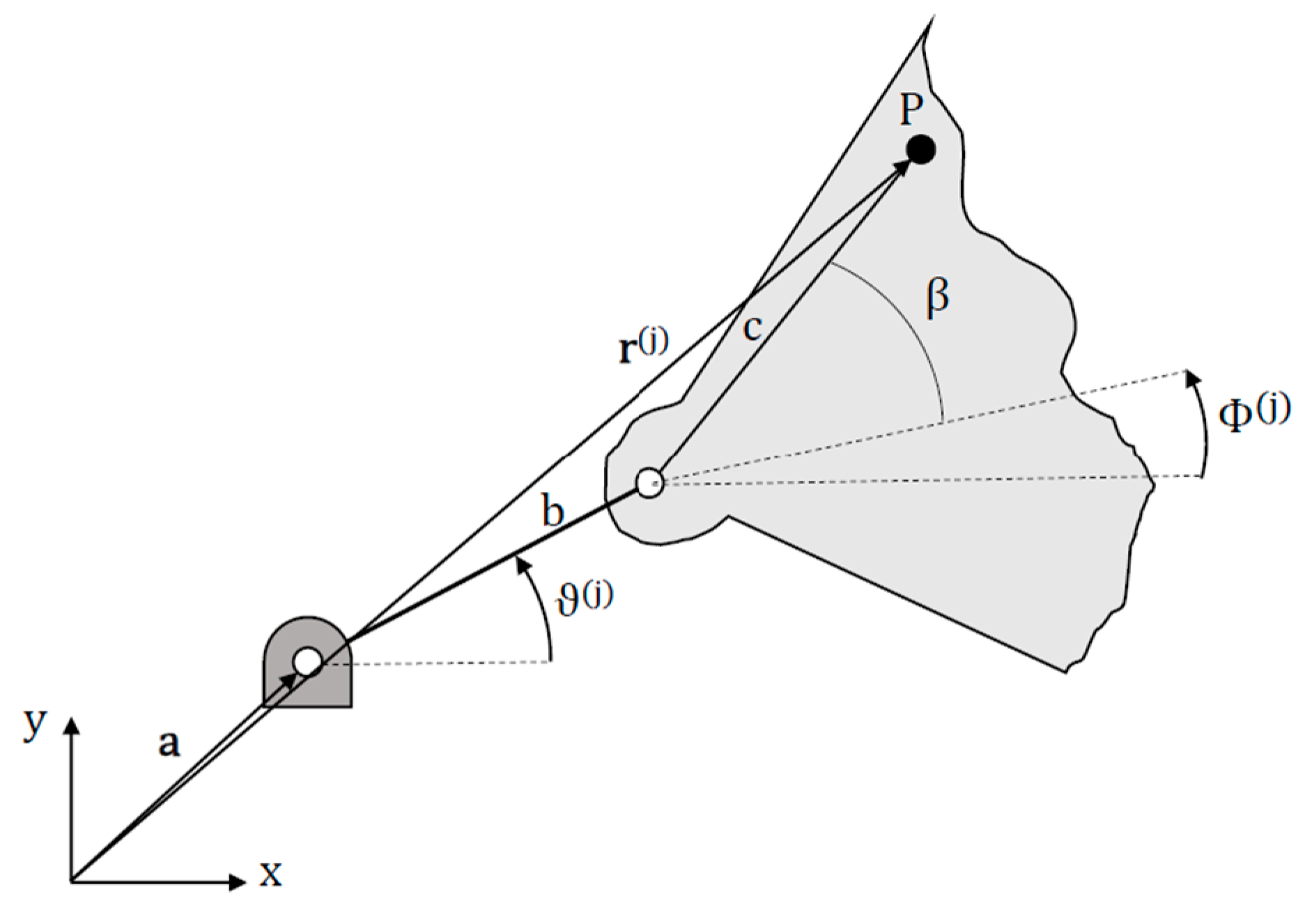
In Equation (1) p(j) is the rigid body j-pose; ϑ(j) is the positional variable, the robot-like joint variable; and, at the j-pose, d ϵ Rn is the array of the linkage dimensional parameters. The rigid body j-pose is given by the position vector of a reference point of the coupler link, r(j) and by the corresponding angle of a line of the coupler link, φ(j). For each pose two scalar component equations are written leading to a total of q = 2m equations for each dyad.
The number of given poses is such to have number of unknowns lower or equal to number of equations available. In these cases, either a determined or an overdetermined system of equations are obtained:
Numerical Algorithm
The idea behind the work is to solve the approximate synthesis by finding the solution of a nonlinear least-squares problem. If the unknowns are grouped in x ϵ Rn+m, the problem can be set as:
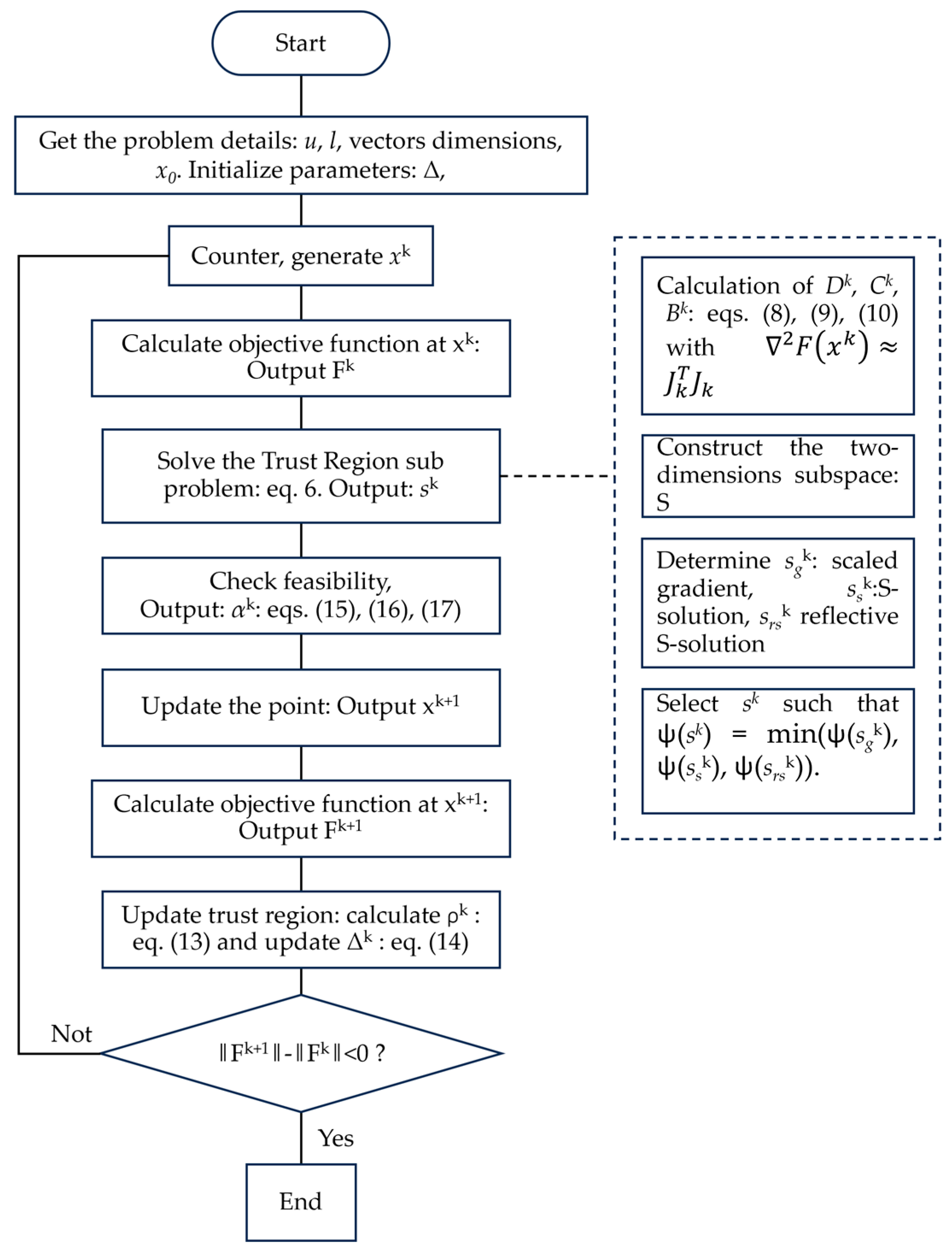
The minimization problem in Equations (3)–(5) is implemented in the built-in lsqnonlin function of Matlab which implements the trust-region-reflective-algorithm proposed by Coleman and Li [54]. The essential idea behind the trust-region method is to approximate F(x) with a quadratic function ψ(s), which reflects the behavior of function F(x) in a neighborhood N, i.e., the trust region, around the current point x.
The method consists of computing trial step s. If F(x+s) < F(x) then the current point x is updated to be (x+s) and the trust region can remain for the next step. Otherwise, x remains unchanged, and region N will be reduced for the next step. Therefore, the challenging issue of the trust-region method is to solve its sub-problem, computing ψ(s). The presence of the bound constraints requires to truncate the step to be strictly feasible and to reflect the trust region solution whenever x lies on the boundary. Here the main steps of the implementation are shown as follows:
- Generate iterate xk such that xk ϵ int(F), int(F) = {x ϵ Rn+m|l < x < u};
- Solve the Trust-region sub problem such to obtain sk;
- Calculate ψ(sk);
- Truncate the trail step sk by αk such that xk+1 = xk + αk sk was strictly feasible.
- Calculate and accordingly update Δk;
- Accept the iterate if ‖Fk+1‖ < ‖Fk‖ with Δk unchanged, otherwise go to the first step with an updated Δk according to ρk calculation of step 5.
The solution of the trust region problem (step 2) is the core of the procedure. The solution involves finding the roots of the secular Equation 1/Δ − 1/‖s‖ = 0 by a Newton iterative process. This approach typically needs computations of Bk eigenvalues. However, the algorithm implemented in the built-in Matlab function reduces the problem to the two-dimensional subspace S such that only a (2 × 2) matrix has to be dealt with.
Subspace S is spanned by s1 and s2. s1 and is in the scaled gradient direction, s2 is the output of a conjugate–gradient process returning either an approximate Newton step or a direction of negative curvature.
Therefore, s is chosen as the best of three computations:
(i) the scaled gradient, (ii) a two-dimensional subspace S solution, i.e., trust region solution and (iii) the reflection of the S solution, i.e., reflected trust region solution. The choice is made by comparing the approximation functions ψ(s) and picking the one that produces its lowest value. The terms involved into the algorithm are as follows:
A flowchart of the algorithm is presented in Figure 1.
3. The STS Assisting Device
We wrote the synthesis equations for the STS four-bar linkage as the vector loop equations for two Revolute–Revolute dyads forming the linkage.
Equations (18) and (19) have five dimensional and m positional parameters as unknowns: ax, ay, b, c, β, ϑ(j). Thus, to have a determined system of nonlinear equations we selected five arbitrary poses, 5 + m = 2m. The prescribed poses were obtained by the frames sequence reported in [24]. The mechanism had to be contained in the area identified by the legs (front and back) and the seat, a square with side of 400 mm, defining the constraints ui, li used in the optimization for the links dimensions and the joints’ locations. The synthesized linkage took an area of 380 mm × 200 mm and the seat rotates from about 6° to 80° raising of about 400 mm. To evaluate the accuracy of the solution we select the mean of the absolute values of the residuals of each equation forming the system as error metrics, i.e., ε. We obtained an error, as follows, ε = 4.49 × 10⁻⁴.
Instead, the errors in position and orientation with respect to the desired poses are reported in Table 1.
Simulation of the Device
The proposed system was developed according to the results of the synthesis procedure detailed in the previous section. In particular, supports and actuator are embedded in the chair design, it is worth noting that the mechanism when folded is very compact and compatible with many chairs or sofa designs, preliminary results were presented in [56].
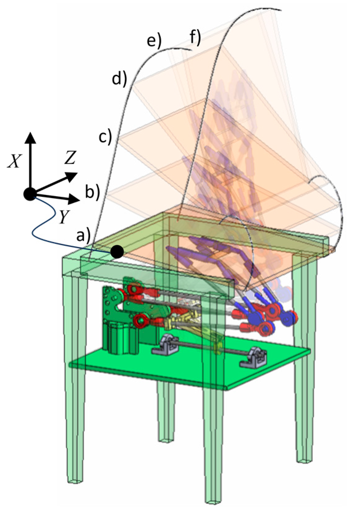
The overall mechanism is composed by the synthesized four-bar-linkage and an additional link connecting the coupler to the mobile platform, which is rigidly connected to the seat, as shown in Figure 3. The function of the additional link depicted in blue is just to report the motion to the point of interest.
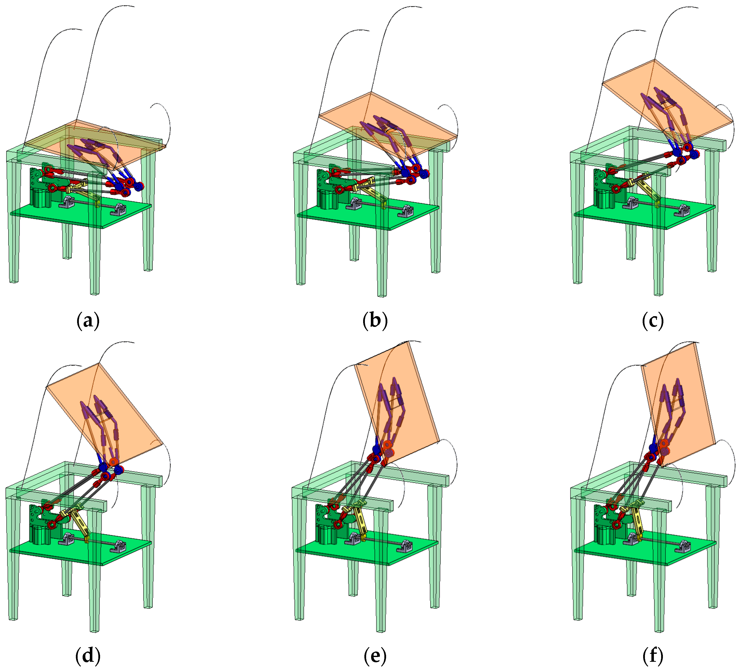
Figure 3 shows a scheme for the final design of the STS mechanism embedded in a chair structure within the given configurations. The trajectories of five points of the seat are also reported. The six configurations (a) to (f) are shown in the motion sequence in Figure 4, by adding to the five prescribed poses another one for representative purposes only.
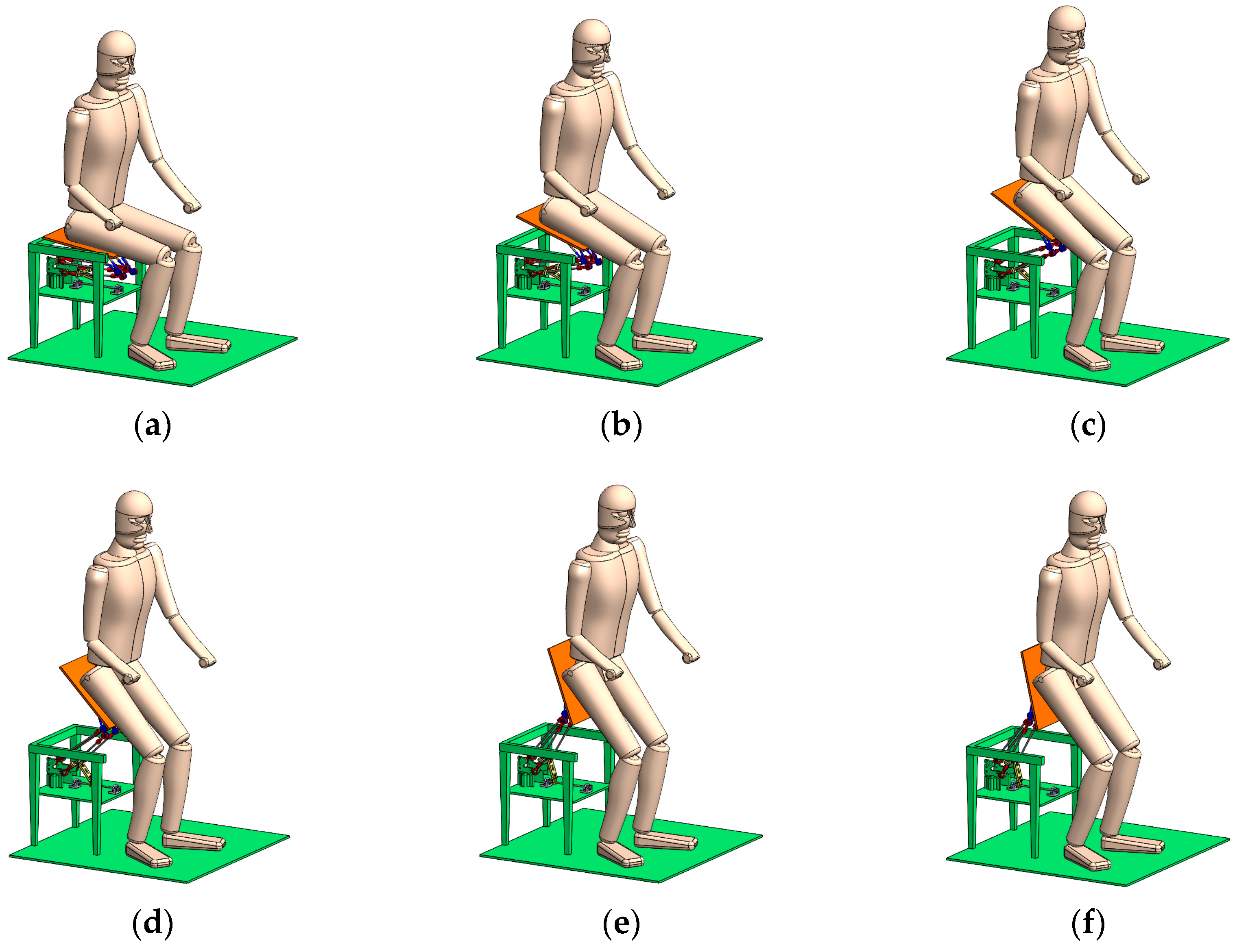
A simulation was carried out considering a 3D model of the human body.
The simplified 3D model of the human body consists of 11 segments, which are connected by 10 revolute joints. Each segment is modeled by a relatively simple geometry that allows full body symmetry with respect to the sagittal plane (left-right symmetry). Segments masses and dimensions were assumed according to anthropometric data reported in Ref. [24]. Each segment was modeled with uniform density and center of mass being coincident with the center of volume. The model was used to reproduce realistic simulation tests, according to previous experiment activity carried out for the validation of the human body model and reported in [24].
The simulation was carried out in quasi-static condition and the speed of movement was set almost equal to the one used in the experimental trials by volunteers. The human body model is 1900 mm tall. During the simulation, the arms are considered as fixed in a natural configuration, in order to not interfere with the movement.
Figure 5 shows the motion sequence of the overall system including the human body model and taking into account the 6 configurations shown in Figure 3.
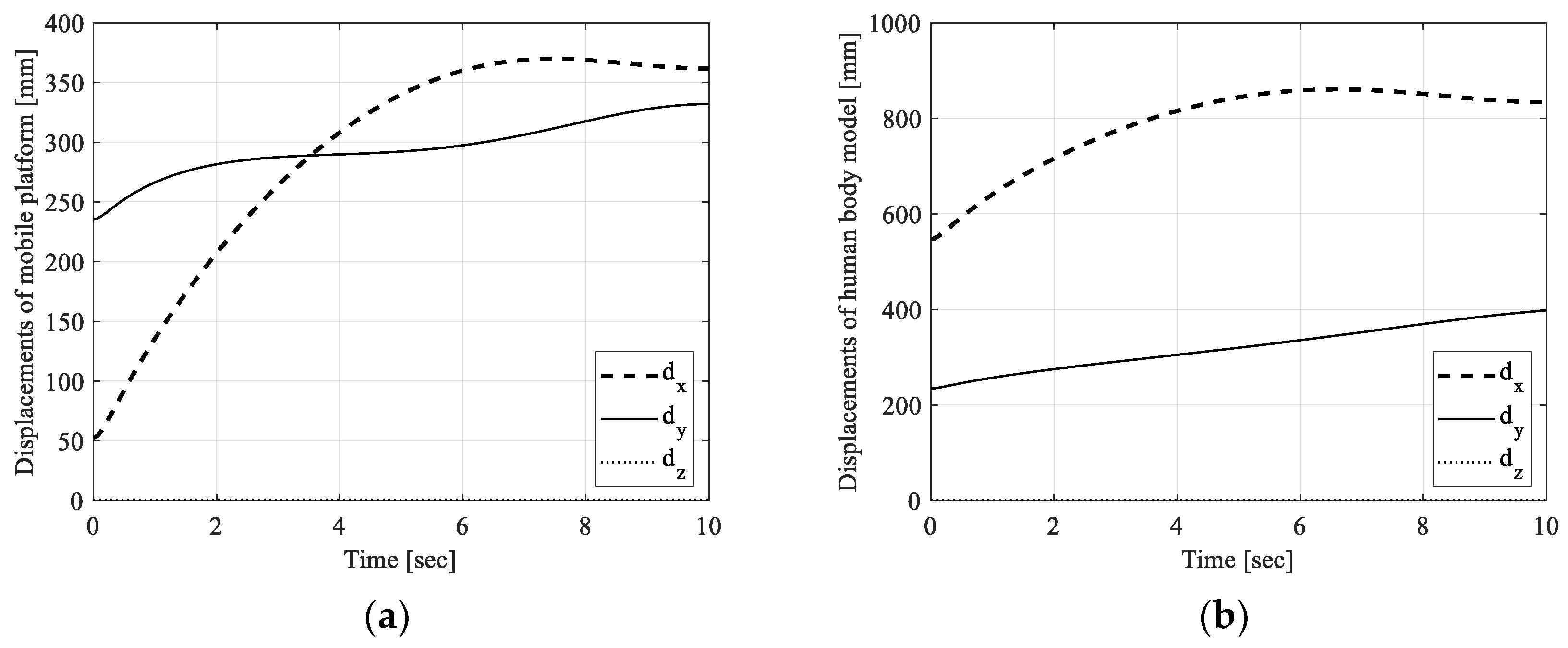
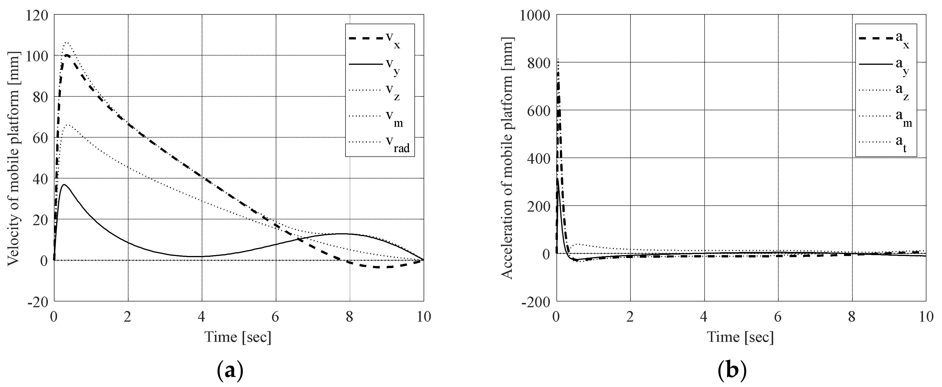
Referring to the simulation reported, numerical results are shown in Figure 6. In particular, Figure 6a reports trajectory of the Center of Mass (CoM) of the trunk for the human body model during the operation, and Figure 6b shows the displacement of seat CoM. Figure 7a,b show the velocity and acceleration for the CoM of the seat during the simulation reported in Figure 5.
The proposed algorithm leads to a unique mechanism but can be modified according to different poses related to anthropometric data of the individual that is willing to use the STS device. Simulations have been carried out using 3D simulation software. Synthesis procedure has been implemented by using a code developed in Matlab environment.
4. Prototyping and Mechatronic Design
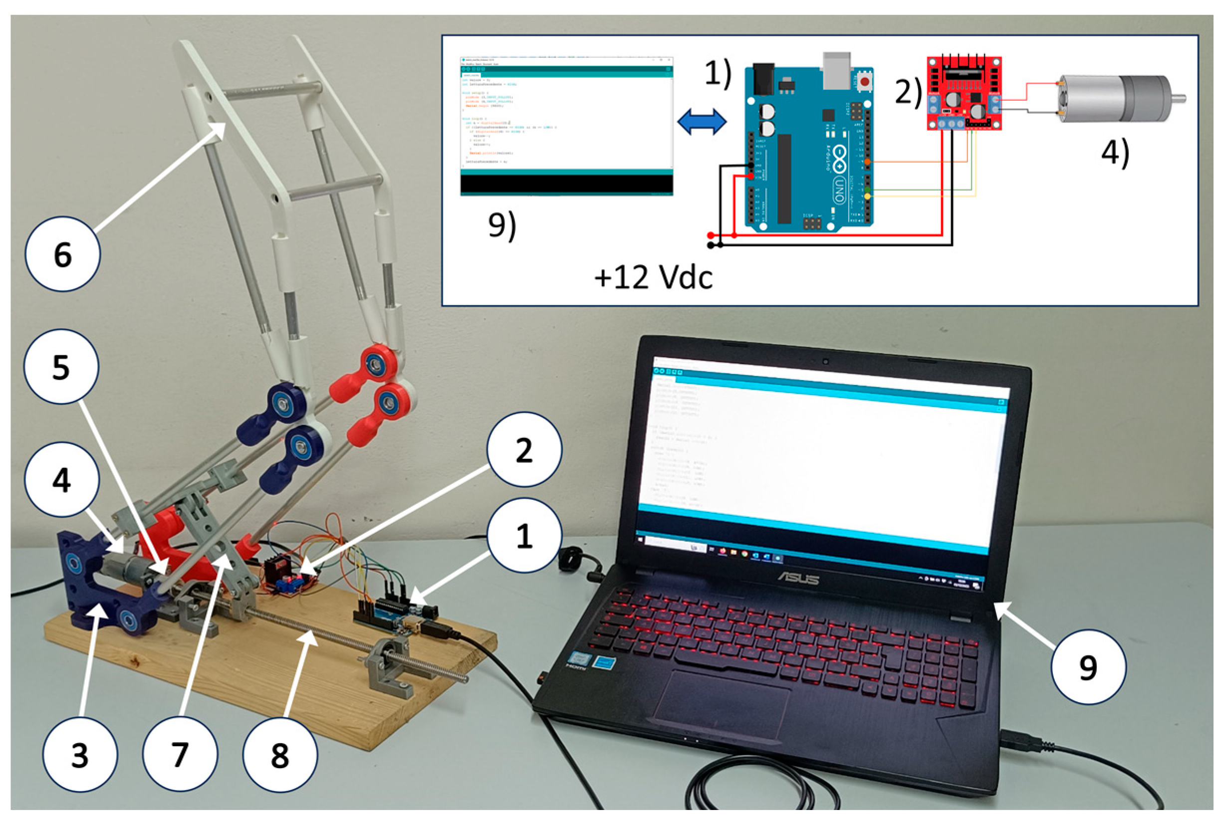
Figure 8 shows a realized testbed with a built prototype developed for first experimental tests to verify the engineering significance of the designed solution and the body motion guidance. The mechatronic design was developed according to the design principles and results presented in [56].
Referring to Figure 8, the EGM30 is a 12 V actuator fully equipped with encoders and a 30:1 reduction gearbox, the related torque is 1.5 kg/cm; the speed is 170 rpm; the current is 530 mA; no load speed is 216 rpm; no load current is 150 mA; the stall current is 2.5 A; the output is 4.22 W; encoder counts per drive shaft turn are 360. The L298N is the Dual H-Bridge Motor Controller having small size and compact design (43 × 43 × 27 mm3). Inside L298N integrated bridges allow high voltages (up to 46 V) and high current (4 A), the mechatronic scheme is kept easy in use in [57].
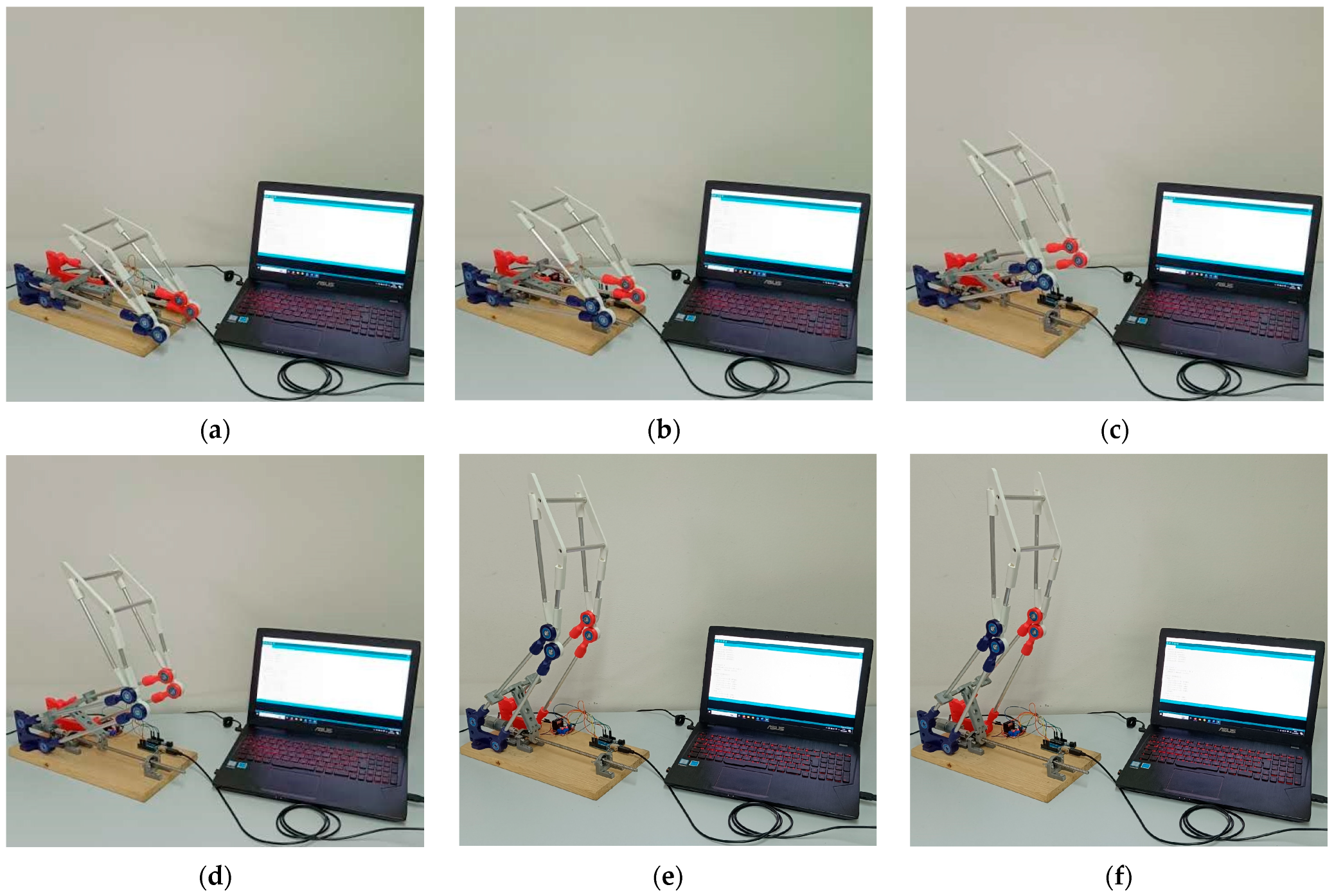
Figure 9 shows the motion sequence for the testbed prototype during experimental tests. It is worth noting that although being manufactured in real scale, the protype is made of lightweight materials and a small actuator for first experimental tests.
The operation of the mechatronic system is controlled by Arduino board that sends signals to an electronic device for motor control. The actuator is connected to the mechanism by a slider crank mechanical system for motion transmission and a screw-nut mechanical system, as shown in Figure 8.
5. Conclusions
In this paper, we have proposed the synthesis, the simulation and first experimental results for a mechanism designed for the Sit-To-Stand operation. The mechanism is based on a four-bar linkage synthetized by solving a five rigid body poses guidance problem. The method is based on approximated solution of the nonlinear system of equations representing the loop equations of the dyads. The algorithm proved to be very accurate, leading to coupler poses very close to those prescribed. Results proved that the method works nicely for the examined cases. The mechanical design is then reported and simulation results are shown, a first fully controlled mechatronic prototype has been built for experimental tests. The device has been designed to be used as backward mechanism being installed on a chair or sofa for accomplishing the motion. The design solution allows a compact system, quite versatile and customizable, according to the needs of the end-user. Future development of the research includes the realization of a real scale prototype with suitable materials and actuation sized for lifting a patient. Nevertheless, it has been verified that the design can be suitable for accomplishing the STS in a real movement. Future development of the proposed work is to design suitable control systems taking into account safety parameters based on safety assessment.
Author Contributions
Conceptualization, P.R., M.R. and E.O.; methodology, P.R. and M.R.; software, P.R.; validation, P.R., M.R. and E.O.; formal analysis, M.R.; investigation, P.R.; resources, E.O. and P.R.; data curation, P.R. and M.R.; writing—original draft preparation, P.R., M.R. and E.O.; writing—review and editing, E.O.; visualization, P.R. and M.R.; supervision, P.R., M.R. and E.O.; funding acquisition, P.R. and E.O. All authors have read and agreed to the published version of the manuscript.
Funding
This work is part ERASMUS+2022-1-ES01-KA220-HED-000089155 MISCE Mechatronics for Improving and Standardizing Competencies in Engineering Description.
Data Availability Statement
No raw data is considered nor are any ethical issues addressed. The simulations are realized with numerical models.
Conflicts of Interest
The authors declare no conflicts of interest.
References
- Ioannidis, J.P.A.; Axfors, C.; Contopoulos-Ioannidis, D.G. Population-level COVID-19 mortality risk for non-elderly individuals overall and for non-elderly individuals without underlying diseases in pandemic epicenters. Environ. Res. 2020, 188, 109890. [Google Scholar] [CrossRef]
- De Pue, S.; Gillebert, C.; Dierckx, E.; Vanderhasselt, M.A.; De Raedt, R.; Van den Bussche, E. The impact of the COVID-19 pandemic on wellbeing and cognitive functioning of older adults. Sci. Rep. 2021, 11, 4636. [Google Scholar] [CrossRef] [PubMed]
- World Health Organization. Assistive Product Specifications and How to Use Them; Electronic Version; World Health Organization: Geneva, Switzerland, 2023; ISBN 978-92-4-002028-3. [Google Scholar]
- Sorli, M.; Figliolini, G.; Pastorelli, S.; Rea, P. Experimental identification and validation of a pneumatic positioning servo-system. In Power Transmission and Motion Control, PTMC 2005; John Wiley & Sons: Hoboken, NJ, USA, 2005; pp. 365–378. [Google Scholar]
- Ceccarelli, M.; Ottaviano, E.; Galvagno, M. A 3-DOF Parallel Manipulator as Earthquake Motion Simulator. In Proceedings of the 7th International Conference on Control, Automation, Robotics and Vision, ICARCV 2002, Singapore, 2–5 December 2002; pp. 944–949. [Google Scholar]
- Kapsalyamov, A.; Jamwal, P.K.; Hussain, S.; Ghayesh, M.H. State of the Art Lower Limb Robotic Exoskeletons for Elderly Assistance. IEEE Access 2019, 7, 95075–95086. [Google Scholar] [CrossRef]
- Yan, T.; Cempini, M.; Oddo, C.M.; Vitiello, N. Review of assistive strategies in powered lower-limb orthoses and exoskeletons. Robot. Auton. Syst. 2015, 64, 120–136. [Google Scholar] [CrossRef]
- Nakamura, K.; Saga, N. Current Status and Consideration of Support/Care Robots for Stand-Up Motion. Appl. Sci. 2021, 11, 1711. [Google Scholar] [CrossRef]
- Ruggiu, M. Kinematic and dynamic analysis of a two-degree-of-freedom spherical wrist. J. Mech. Robot. 2010, 2, 031006. [Google Scholar] [CrossRef]
- Deidda, R.; Mariani, A.; Ruggiu, M. On the kinematics of the 3-RRUR spherical parallel manipulator. Robotica 2010, 28, 821–832. [Google Scholar] [CrossRef]
- Imamura, Y.; Endo, Y.; Yoshida, E. Simulation–based Design of Transfer Support Robot and Experimental Verification. In Proceedings of the 2019 2nd IEEE International Conference on Soft Robotics (RoboSoft), Seoul, Republic of Korea, 14–18 April 2019. [Google Scholar]
- Santos, A.V.F.; Licursi, L.A.; Amaral, M.F.; Cavalcanti, A.; Silveira, Z.C. User-centered design of a customized assistive device to support feeding. Procedia CIRP 2019, 84, 743–748. [Google Scholar]
- Scaletta, T.; Komada, S.; Oboe, R. Development of a Human Assistive Robot to Support Hip Joint Movement during Sit-to-stand Using Non-linear Springs. IEEJ J. Ind. Appl. 2016, 5, 261–266. [Google Scholar] [CrossRef]
- Roebroeck, M.E.; Doorenbosch, C.A.; Harlaar, J.; Jacobs, R.; Lankhorst, G.J. Biomechanics and muscular activity during sit-to-stand transfer. Clin. Biomech. 1994, 9, 235–244. [Google Scholar] [CrossRef]
- Graham Lift. Available online: https://www.vitalitymedical.com/lumex-stand-assist-patient-transport-lift-graham-field-lf1600.html (accessed on 10 November 2023).
- QuickMove. Webpage. Available online: https://www.handicare.com/en/product/quickmove/ (accessed on 10 November 2023).
- Molift Quick Raiser 2, Webpage. Available online: https://www.etac.com/products/patient-handling/sit-to-stand-aids/molift-quick-raiser-2/ (accessed on 10 November 2023).
- Zhou, B.; Xue, Q.; Yang, S.; Zhang, H.; Wang, T. Design and control of a sit-to-stand assistive device based on analysis of kinematics and dynamics. Automatika 2021, 62, 353–364. [Google Scholar] [CrossRef]
- Hojjati Najafabadi, A.; Amini, S.; Farahmand, F. Mechanical Design and Simulation of a Saddle-Assistive Device for Sit-to-Stand Transfer in Healthy Subjects. Int. J. Adv. Des. Manuf. Technol. 2017, 10, 37–44. [Google Scholar]
- Liang, X.; Chen, F. A Study on Design of Adaptive Assistant Devices for the Sit-To-Stand. In Proceedings of the 2021 IEEE International Conference on Power, Intelligent Computing and Systems (ICPICS), Shenyang, China, 29–31 July 2021; pp. 196–201. [Google Scholar] [CrossRef]
- Biomechanics Dataset of Healthy Human Walking at Various Conditions. Available online: https://github.com/timvanderzee/human-walking-biomechanics (accessed on 10 October 2023).
- Nandikolla, V.K.; Bochen, R.; Meza, S.; Garcia, A. Experimental Gait Analysis to Study Stress Distribution of the Human Foot. J. Med. Eng. 2017, 2017, 3432074. [Google Scholar] [CrossRef] [PubMed]
- Ottaviano, E.; Ceccarelli, M.; Palmucci, F. An application of CaTraSys, a cable-based parallel measuring system for an experimental characterization of human walking. Robotica 2010, 28, 119–133. [Google Scholar] [CrossRef]
- Rea, P.; Ottaviano, E. Functional Design for Customizing Sit-To-Stand Assisting Devices. J. Bionic Eng. 2018, 15, 83–93. [Google Scholar] [CrossRef]
- Pasinetti, S.; Nuzzi, C.; Covre, N.; Luchetti, A.; Maule, L.; Serpelloni, M.; Lancini, M. Validation of Marker-Less System for the Assessment of Upper Joints Reaction Forces in Exoskeleton Users. Sensors 2020, 20, 3899. [Google Scholar] [CrossRef] [PubMed]
- Lam, W.W.T.; Tang, Y.M.; Fong, K.N.K. A systematic review of the applications of markerless motion capture (MMC) technology for clinical measurement in rehabilitation. J. NeuroEng. Rehabil. 2023, 20, 57. [Google Scholar] [CrossRef]
- Rahul, M. Review on motion capture technology. Glob. J. Comput. Sci. Technol. 2018, 18, 3–6. [Google Scholar]
- Corazza, S.; Mündermann, L.; Gambaretto, E.; Ferrigno, G.; Andriacchi, T.P. Markerless motion capture through visual hull, articulated ICP and subject specific model generation. Int. J. Comput. Vis. 2010, 87, 156–169. [Google Scholar] [CrossRef]
- Alves, J.; Lima, T.M.; Gaspar, P.D. Novel Design of Assistive Technologies Based on the Interconnection of Motion Capture and Virtual Reality Systems to Foster Task Performance of the Ageing Workforce. Designs 2023, 7, 23. [Google Scholar] [CrossRef]
- Muñoz, D.; De Marchis, C.; Gizzi, L.; Severini, G. Predictive simulation of sit-to-stand based on reflexive-controllers. PLoS ONE 2022, 17, e0279300. [Google Scholar] [CrossRef] [PubMed]
- Raisin, S.N.; Jamaludin, J.; Jamal, M.; Farah, A.; Hazwani, N.; Naeem, B. Cyber-Physical System (CPS) Application—A Review. REKA ELKOMIKA J. Pengabdi. Kpd. Masy. 2020, 1, 52–65. [Google Scholar] [CrossRef]
- Arafsha, F.; Laamarti, F.; El Saddik, A. Cyber-Physical System Framework for Measurement and Analysis of Physical Activities. Electronics 2019, 8, 248. [Google Scholar] [CrossRef]
- El Saddik, A. Digital Twins: The Convergence of Multimedia Technologies. IEEE Multimed. 2018, 25, 87–92. [Google Scholar] [CrossRef]
- Lu, Y.; Zheng, H.; Chand, S.; Xia, W.; Liu, Z.; Xu, X.; Wang, L.; Qin, Z.; Bao, J. Outlook on human-centric manufacturing towards Industry 5.0. J. Manuf. Syst. 2022, 62, 612–627. [Google Scholar] [CrossRef]
- Norheim, K.L.; Samani, A.; Madeleine, P. The effects of age on response time, accuracy, and shoulder/arm kinematics during hammering. Appl. Ergon. 2020, 90, 103157. [Google Scholar] [CrossRef] [PubMed]
- Kačerová, I.; Kubr, J.; Hořejší, P.; Kleinová, J. Ergonomic Design of a Workplace Using Virtual Reality and a Motion Capture Suit. Appl. Sci. 2022, 12, 2150. [Google Scholar] [CrossRef]
- Babadi, S.Y.; Daneshmandi, H. Effects of virtual reality versus conventional balance training on balance of the elderly. Exp. Gerontol. 2021, 153, 111498. [Google Scholar] [CrossRef]
- Liagkou, V.; Salmas, D.; Stylios, C. Stylios, Realizing Virtual Reality Learning Environment for Industry 4.0. Procedia CIRP 2019, 79, 712–717. [Google Scholar] [CrossRef]
- Abuwarda, Z.; Mostafa, K.; Oetomo, A.; Hegazy, T.; Morita, P. Wearable devices: Cross benefits from healthcare to construction. Autom. Constr. 2022, 142, 104501. [Google Scholar] [CrossRef]
- Lemos, J.; Gaspar, P.D.; Lima, T.M. Individual Environmental Risk Assessment and Management in Industry 4.0: An IoT-Based Model. Appl. Syst. Innov. 2022, 5, 88. [Google Scholar] [CrossRef]
- McDevitt, S.; Hernandez, H.; Hicks, J.; Lowell, R.; Bentahaikt, H.; Burch, R.; Ball, J.; Chander, H.; Freeman, C.; Taylor, C.; et al. Wearables for Biomechanical Performance Optimization and Risk Assessment in Industrial and Sports Applications. Bioengineering 2022, 9, 33. [Google Scholar] [CrossRef] [PubMed]
- Nikolakis, N.; Maratos, V.; Makris, S. A cyber physical system (CPS) approach for safe human-robot collaboration in a shared workplace. Robot. Comput.-Integr. Manuf. 2019, 56, 233–243. [Google Scholar] [CrossRef]
- Balan, L.; Bone, G.M. Real-time 3D Collision Avoidance Method for Safe Human and Robot Coexistence. In Proceedings of the 2006 IEEE/RSJ International Conference on Intelligent Robots and Systems, Beijing, China, 9–15 October 2006; pp. 276–282. [Google Scholar] [CrossRef]
- Flacco, F.; Kröger, T.; De Luca, A.; Khatib, O. A depth space approach to human-robot collision avoidance. In Proceedings of the 2012 IEEE International Conference on Robotics and Automation, Saint Paul, MN, USA, 14–18 May 2012; pp. 338–345. [Google Scholar] [CrossRef]
- Burmester, L. Lehrbuch der Kinematik; A. Felix: Leipzig, Germany, 1888. [Google Scholar]
- Sandor, G.N.; Erdman, A. Advanced Mechanism Design: Analysis and Synthesis; Prentice-Hall, Inc.: Hoboken, NJ, USA, 1984; Volume 2. [Google Scholar]
- Ravani, B.; Roth, B. Motion synthesis using kinematic mappings. ASME J. Mech. Transm. Autom. Des. 1983, 105, 460–467. [Google Scholar] [CrossRef]
- Hayes, M.; Zsombor-Murray, P. Solving the Burmester problem using kinematic mapping. In Proceedings of the ASME 2002 International Design Engineering Technical Conferences and Computers and Information in Engineering Conference, Proc. ASME DETC’2002, Montreal, QC, Canada, 29 September–2 October 2002. #MECH-34378. [Google Scholar]
- Brunnthaler, K.; Pfurner, M.; Husty, M. Synthesis of Planar Four-Bar Mechanisms. Trans. CSME 2006, 30, 297–313. [Google Scholar] [CrossRef]
- Bottema, O.; Roth, B. Theoretical Kinematics; North-Holland Pub. Co.: New York, NY, USA, 1979. [Google Scholar]
- Hunt, K.H. Kinematic Geometry of Mechanisms; Oxford University Press: New York, NY, USA, 1978. [Google Scholar]
- McCarthy, J.M. Geometric Design of Linkages; Springer: New York, NY, USA, 2000. [Google Scholar]
- Yao, J.; Angeles, J. Computation of all optimum dyads in the approximate synthesis of planar linkages for rigid-body guidance. Mech. Mach. Theory 2000, 35, 1065–1078. [Google Scholar] [CrossRef]
- Coleman, T.F.; Li, Y. An Interior, Trust Region Approach for Nonlinear Minimization Subject to Bounds. SIAM J. Optim. 1996, 6, 418–445. [Google Scholar] [CrossRef]
- Reimer, S.M.F.; Abdul-Sater, K.; Lueth, T.C. Bio-Kinematic Design of Individualized Lift-Assist Devices. New Trends Med. Serv. Robot. Mech. Mach. Sci. 2018, 48, 59–72. [Google Scholar]
- Rea, P.; Ruggiu, M.; Ottaviano, E. A Sit-to-Stand Assisting Device for Accomplishing Daily-Life Activities. In Advances in Mechanism and Machine Science, Proceedings of the 16th IFToMM World Congress 2023, Tokyo, Japan, 5–10 November 2023; Mechanisms and Machine Science; Okada, M., Ed.; Springer: Cham, Switzerland, 2023; Volume 147. [Google Scholar] [CrossRef]
- Figliolini, G.; Rea, P. Overall design of Ca.U.M.Ha. robotic hand for harvesting horticulture products. Robotica 2006, 24, 329–331. [Google Scholar] [CrossRef]
Figure 1.
Flowchart of the proposed algorithm.

Figure 2.
Notation of the RR dyad.

Figure 3.
A scheme for six configurations (a–f) of the designed mechanism to accomplish the STS operation considering five prescribed poses and an additional one for representation form (trajectories of points of interests and the reference system are shown).
Figure 3.
A scheme for six configurations (a–f) of the designed mechanism to accomplish the STS operation considering five prescribed poses and an additional one for representation form (trajectories of points of interests and the reference system are shown).

Figure 4.
Motion sequence during the simulation for the operation of the system as function of the input joint angle: (a) ϑ = 7°, (b) ϑ = 18°, (c) ϑ = 30°, (d) ϑ = 45°, (e) ϑ = 70°, (f) ϑ = 77°.
Figure 4.
Motion sequence during the simulation for the operation of the system as function of the input joint angle: (a) ϑ = 7°, (b) ϑ = 18°, (c) ϑ = 30°, (d) ϑ = 45°, (e) ϑ = 70°, (f) ϑ = 77°.

Figure 5.
Simulation snapshots for the system including the human body model when the input joint angles are: (a) ϑ = 7°, (b) ϑ = 18°, (c) ϑ = 30°, (d) ϑ = 45°, (e) ϑ = 70°, (f) ϑ = 77°.
Figure 5.
Simulation snapshots for the system including the human body model when the input joint angles are: (a) ϑ = 7°, (b) ϑ = 18°, (c) ϑ = 30°, (d) ϑ = 45°, (e) ϑ = 70°, (f) ϑ = 77°.

Figure 6.
Results for the simulation reported in Figure 4: (a) Center of Mass (CoM) displacement of the trunk of the human body model; (b) displacement of the CoM of the mobile platform, where the seat is installed.
Figure 6.
Results for the simulation reported in Figure 4: (a) Center of Mass (CoM) displacement of the trunk of the human body model; (b) displacement of the CoM of the mobile platform, where the seat is installed.

Figure 7.
Results for the simulation reported in Figure 4: (a) velocity of the CoM of the mobile platform; (b) acceleration of the CoM for the mobile platform, where the seat is installed.
Figure 7.
Results for the simulation reported in Figure 4: (a) velocity of the CoM of the mobile platform; (b) acceleration of the CoM for the mobile platform, where the seat is installed.

Figure 8.
Experimental testbed: (1) Arduino board, (2) Electronic device for motor control (L298N Dual H-Bridge Motor Controller), (3) STS System, (4) EMG30—DC Motor 12 V 0.53 A 170 rpm with hall encoder, (5) Flexible guide joint, (6) Chair seat, (7) Slider crank mechanical system for motion transmission, (8) Screw-Nut mechanical system, (9) PC.

Figure 9.
Motion sequence of the experimental tests for the designed STS device for the six configurations (a–f).
Figure 9.
Motion sequence of the experimental tests for the designed STS device for the six configurations (a–f).


Table 1.
Absolute errors in position and orientation.
| j | |||
|---|---|---|---|
| 1 | 0.0101 | 0.0010 | 0.1120 |
| 2 | 0.0143 | 0.0026 | 0.3113 |
| 3 | 0.0072 | 0.0040 | 0.2175 |
| 4 | 0.0146 | 0.0098 | 0.4528 |
| 5 | 0.0033 | 0.0049 | 0.0591 |
Disclaimer/Publisher’s Note: The statements, opinions and data contained in all publications are solely those of the individual author(s) and contributor(s) and not of MDPI and/or the editor(s). MDPI and/or the editor(s) disclaim responsibility for any injury to people or property resulting from any ideas, methods, instructions or products referred to in the content. |
© 2024 by the authors. Licensee MDPI, Basel, Switzerland. This article is an open access article distributed under the terms and conditions of the Creative Commons Attribution (CC BY) license (https://creativecommons.org/licenses/by/4.0/).
Share and Cite
MDPI and ACS Style
Rea, P.; Ruggiu, M.; Ottaviano, E. Synthesis and Prototyping of a Sit-to-Stand Assisting Device. Machines 2024, 12, 33. https://doi.org/10.3390/machines12010033
AMA Style
Rea P, Ruggiu M, Ottaviano E. Synthesis and Prototyping of a Sit-to-Stand Assisting Device. Machines. 2024; 12(1):33. https://doi.org/10.3390/machines12010033
Chicago/Turabian StyleRea, Pierluigi, Maurizio Ruggiu, and Erika Ottaviano. 2024. "Synthesis and Prototyping of a Sit-to-Stand Assisting Device" Machines 12, no. 1: 33. https://doi.org/10.3390/machines12010033
Note that from the first issue of 2016, this journal uses article numbers instead of page numbers. See further details here.