Article

Utilizing Dynamic Analysis in the Complex Design of an Unconventional Three-Wheeled Vehicle with Enhancing Cornering Safety

1
Department of Transport and Handling Machines, Faculty of Mechanical Engineering, University of Žilina, Univerzitná 8215/1, 010 26 Žilina, Slovakia
2
Department of Applied Mechanics, Faculty of Mechanical Engineering, University of Žilina, Univerzitná 8215/1, 010 26 Žilina, Slovakia
3
Institute of Transport, Faculty of Mechanical Engineering, VSB—Technical University of Ostrava, 17. Listopadu 2172/15, 708 00 Ostrava, Czech Republic
*
Author to whom correspondence should be addressed.
Machines 2023, 11(8), 842; https://doi.org/10.3390/machines11080842
Submission received: 11 July 2023 / Revised: 13 August 2023 / Accepted: 16 August 2023 / Published: 18 August 2023
(This article belongs to the Special Issue Recent Analysis and Research in the Field of Vehicle Traffic Safety)

Abstract

:
Current trends in the transportation industry prioritize competitive rivalry, compelling manufacturers to prioritize concepts such as quality and reliability. These concepts are closely associated with public expectations of safety, vehicle lifespan, and trouble-free operation. However, the public must recognize that a vehicle weighing several hundred kilograms, moving at a non-zero speed, only contacts the road surface through a few points (depending on the number of wheels), each no larger than a human palm. Therefore, it is imperative to operate the vehicle in a manner that optimizes the behavior of these contact points. There are situations where drivers find themselves requiring dynamic vehicle handling, often unpredictable with a high degree of uncertainty. Rapid changes in direction become necessary in these cases. Such maneuvers can pose a significant risk of rollover for three-wheeled vehicles. Hence, the vehicle itself should contribute to increased ride safety. This paper presents key findings from the development of an unconventional three-wheeled vehicle utilizing the delta arrangement. Rollover safety for three-wheeled vehicles is currently well-managed, thanks to the utilization of electronic or mechatronic systems in delta-type vehicles to enhance stability. However, these systems require additional components. In contrast, the proposed control system operates solely on a mechanical principle, eliminating operational costs, energy consumption, maintenance expenses, and similar factors. The study also explores the absence of equivalent suspension and steering systems for front-wheel steering. Such designs are lacking in both practical applications and theoretical realms. Analytical and simulation calculations are compared in this study, highlighting the effectiveness of the newly proposed control system in enhancing stability and safety compared to conventional front-wheel suspension systems. Simulation programs provide more realistic results than analytical calculations due to their ability to account for dynamic effects on vehicle components and passengers, which is practically unfeasible in analytical approaches. Furthermore, this study focuses on investigating the fatigue life of material frames subjected to dynamic loading, which is a crucial aspect of ensuring safety. It is essential to have various testing devices to examine the fatigue life of materials under both uniaxial and multiaxial loading conditions. However, obtaining experimental results for fatigue life measurements of specific materials, which can be directly applied to one’s research, poses significant challenges. Hence, the proposed testing device plays a vital role in measuring material fatigue life and advancing the development of unconventional transportation methods. The information about the original testing device aligns perfectly with the article’s emphasis on dynamic analysis. The ultimate objective of all these efforts is to put the vehicle into practical operation for commercial utilization.

1. Introduction

As part of its “Advancing Technology” grant scheme, the Volkswagen Foundation has provided support for a project that focuses on the structural design of a three-wheeled electric vehicle known as the E3-kolka. This innovative vehicle aims to improve passenger safety during cornering by employing mechanical principles (Figure 1a). The design, which has been patented [1], is extensively discussed in the article [2]. While its primary application lies within the domain of road vehicles in the motorcycle industry, the design’s benefits extend to any scenario where enhanced stability of overall structures is required for the operation of three-wheeled vehicles.
In the quest to identify an equivalent suspension and steering system for the front-steered wheel (delta arrangement), the absence of such designs has been noted. These designs are lacking not only in practical applications but also in theoretical discussions. According to [3], accidents involving three-wheeled vehicles contribute to over 33% of severe injuries and fatalities among all incidents. Moreover, when considering the proportion of accidents involving three-wheeled vehicles in relation to the total number of road vehicle accidents, this statistic becomes even more alarming [4]. This fact highlights the significance of the current project and represents the initial step towards its successful resolution—acknowledging the problem. Therefore, this study presents the key findings achieved during the development of this vehicle, with a specific focus on the ongoing modifications (optimization) of its design.
The problem of stability can be addressed from a physical perspective by considering the balance between stabilizing and destabilizing moments in a vehicle. A comparison between four-wheeled and three-wheeled vehicles leads to the conclusion that four-wheeled vehicles exhibit better stability [5,6]. The reduced stability of three-wheeled vehicles, when considering the same geometry (track width and center of gravity height), is attributed to the lower perpendicular distance from the vehicle’s weight (mass) to the axis of rollover (connecting the front and rear wheels) compared to a four-wheeled vehicle [7]. This understanding led to the development of a new front-steered wheel suspension system (Figure 1b) that allows for both wheel displacement and rotation, thus increasing the lever arm of the gravitational force and consequently the stabilizing moment. The approach to achieving the desired mobility capabilities was published by the authors in [2,7,8,9]. This represents the second step in the process of theoretical improvement. After analyzing the current state, it can be concluded that even the closest design solutions differ significantly from the E3-kolka. For example, in a study by Spânu et al. [10], a design of a three-wheeled vehicle with a centrally located articulated joint was presented. Another contribution to the stability study is found in the research presented in the article [11], where the authors proposed a general integrated reconfigurable vehicle model applicable to both four-wheeled and three-wheeled vehicles (Tadpole, Delta). This model was compared with three vehicles using the CarSim program to verify its performance. The results demonstrated that this proposed reconfigurable vehicle model is useful for stability studies, including aspects such as lateral stability, improved controllability, and rollover prevention, as well as for designing vehicle control systems with various activation systems. Furthermore, other analyzed works exhibited significant differences [12,13,14,15,16].
Currently, there exists a design proposal for a mechanism (Figure 1b) that enhances the stability of three-wheeled vehicles while cornering. The subsequent implementation of this mechanism into a physical vehicle model holds great importance. The authors addressed this issue in their article [2] by devising the geometry of the vehicle frame. This particular frame was purposefully crafted to accommodate the steering mechanism and all other vehicle components. Since the project itself embodies the concept of a “green vehicle” (aiming to reduce fuel consumption and CO2 emissions [17,18] and employ electric propulsion), it was decided to utilize a commercial aluminum alloy, EN AW6063, as the construction material for the frame. This strategic decision resulted in a weight reduction of the frame by up to 40 kg when compared to the parameters of a similar vehicle, the Kyburz Classic (Figure 2) as mentioned in [7]. Moreover, the lowering of the frame’s center of gravity by 0.15 m has a positive influence on stability by reducing the destabilizing moment caused by centrifugal force.
The final design proposal for the frame is preceded by a substantial effort invested in determining the physical properties of the construction material. The authors addressed this issue through extensive research described in detail in [2,7,8,19]. The yield strength of the EN AW 6063 material was experimentally determined using a tensile test, resulting in an average value of 247 MPa. After welding (using the TIG method), the yield strength decreased to 110 MPa. However, by implementing welding techniques such as preheating the material to 150 °C, using a filler material (AlSi5), modifying the weld surface, and carefully controlling welding parameters, the tensile strength after welding was increased from 110 MPa to 167 MPa [2]. Additionally, a change in hardness from 69 HVM to 50 HVM was observed. Through welding simulation in the SysWeld program, the temperature distribution within the material was determined by optimizing welding parameters to achieve maximum strength. The relationship between the decrease in hardness at specific locations and the temperature reached during welding was analyzed, revealing an exponential decline in this relationship.
The research on the material involved the construction of a unique testing device to measure the fatigue life of the frame material under both uniaxial and multiaxial conditions. However, the realization of the actual construction of the testing device required an analysis of the forces acting on the proposed vehicle. It was found that centrifugal forces come into play when the vehicle is maneuvering through corners, and these forces are correlated with the torsional stiffness of the vehicle frame [20,21,22]. Additionally, there is a significant load acting in the vertical direction, attributed to gravitational forces exerted by the vehicle and passengers. These forces result in a bending moment. Similar conclusions were drawn in other studies as well [23,24]. The experimental testing device depicted in Figure 3 was created to assess the fatigue properties of the structural material. It was specifically designed to apply both flexural and torsional loads, as well as their combination. The authors have previously published some information about this testing device in [2,7,8,19,25,26]. The research conducted on the fatigue life of the welded structural material EN AW 6063 confirmed the suitability of the chosen structural material [8]. In this article, our objective is to emphasize additional crucial aspects that should be considered during the development of the testing device and the analysis of the results obtained from measuring the multiaxial fatigue life of the E3-kolka frame material.
In today’s competitive commercial world, manufacturers face a compelling need to prioritize concepts such as quality and reliability. These terms are closely associated in the public’s perception with attributes like safety, durability, and trouble-free operation. Therefore, this article places significant emphasis on investigating the factors that influence these fundamental concepts. The aim is to achieve the most accurate determination of fatigue life under specific boundary conditions. As a result, there has been a notable increase in attention dedicated to the development of a testing device capable of accurately capturing multiaxial fatigue characteristics. Given the diverse combinations of loads encountered in practical scenarios, it becomes necessary to assemble multiple multiaxial fatigue testing devices capable of simulating these load combinations. Consequently, one of the aims of this study, in line with the referenced works [2,7,8,19,27], is to establish a comprehensive testing methodology for evaluating the fatigue life under the combined cyclic loading effects of bending and torsion.
As evident from the existing literature, a considerable number of studies have been published that have addressed the operational principles of the experimental device (Figure 3), the adjustment of load levels, the achieved sample deformations, and stresses, as well as the measurement methodology. However, it was equally important to approach the device design from the perspective of its fundamental dynamic properties, as discussed in this paper. Only after determining the material and technological properties could numerical simulations of the vehicle frame be conducted using the Ansys program [7]. The obtained values of the equivalent von Mises stress in the frame, considering the total weight of the vehicle (151.5 kg) with a passenger (130 kg) subjected to twice the Earth’s gravitational acceleration (2∙g), averaged at 20 MPa. This corresponds to the fatigue life of the experimental material being close to 107 cycles [7]. Therefore, the utilization of the given component is considered safe.
The theoretical improvement in vehicle stability was demonstrated through analytical calculations in [8], which were then compared with a conventional three-wheeled vehicle of the same geometry. The maximum effect, represented by the increase in cornering speed, reached up to 19%. It is important to consider that in this case, a vehicle weighing over 250 kg, moving at a significant non-zero speed, maintains contact with the road surface through only three points, which are no larger than a human palm. Therefore, it is advisable to handle the vehicle in a manner that aligns with the optimal behavior of these three points. However, certain situations may require the driver to navigate the vehicle more dynamically, often arising unexpectedly, such as when a child or an animal suddenly appears on the road. In such cases, it becomes necessary to perform a driving maneuver involving a rapid change in direction. Hence, the vehicle itself should contribute to enhancing driving safety. Therefore, the comparison of results between the conventional three-wheeled vehicle and the proposed vehicle with enhanced rollover safety through MBS simulation is another aim of this article. The nonlinear MBS simulation results will provide a more accurate description of the real vehicle’s behavior during the experiment. This improvement is attributed to the fact that the linear analytical model did not account for factors such as material stiffness, vehicle suspension, and others.
The ultimate goal of all steps is to bring the vehicle into practical operation, specifically for commercial utilization.

2. Materials and Methods

According to Regulation, issued by the Ministry of Transport and Construction of the Slovak Republic on 27 April 2018, by Section 136, Paragraph 3, Letter d) of Act No. 106/2018 Coll. on the operation of vehicles in road traffic and amendments to certain laws, the following requirements must be met [28]:
  • The design of the axle steering mechanism must prevent shocks and vibrations in the steering system, as discussed in the publication [7].
  • The steering axle must return to the straight position after completing a turn or require less force than that needed to initiate a change in direction, as addressed in the publication [7].
  • When transitioning from a straight path to a curve with a radius of 12 m at a speed of 10 km/h, the manual force applied to the steering wheel must not exceed 250 N. The authors further discuss the fulfillment of this requirement in the article.

2.1. Variant Solutions for Vehicle Design Modifications to Meet Roadworthiness Requirements

The requirement is to achieve a maximum steering wheel force of 250 N on the vehicle at a defined turn radius of 12 m and a speed of 10 km/h. It is widely recognized that turning the steering wheel is easier when the vehicle is in motion, even at a minimal speed. Therefore, it was determined that the maximum force required to turn the steering wheel for a stationary vehicle (with zero forward speed) would be precisely 250 N. The vehicle’s motion at a speed of 10 km/h will result in a reduction of this force, thereby meeting the requirement for the maximum allowable force. In the constructed prototype (Figure 1 on the left), the steering shaft was rotated using a torque wrench. Based on measurements taken on the constructed prototype, it was determined that a maximum moment of Mmax = 58 N·m is required for a complete rotation of the steering wheel. The steering wheel used has a diameter of Dv = 350 mm. Subsequently, the maximum force Fmax required to turn the steering wheel is calculated using Equation (1):
F max = M max D v 2 = 2 M max D v .
If the force exceeds a certain threshold, it will be necessary to integrate a transmission system into the vehicle’s design, featuring an appropriately determined gear ratio as defined by Equation (2):
M v = M max i .
If it is necessary to incorporate an auxiliary gear into the vehicle, alternative designs for the placement of the planetary gearbox are illustrated in Figure 4. Ultimately, it will be necessary to evaluate the impacts of each proposal.
The first option for placing the gearbox (Figure 4b) involves mounting it onto the frame above the pinion and aligning the output shaft of the gearbox with a small gearwheel. Subsequently, the system of cardan shafts originating from the steering wheel would be adjusted to connect to the input shaft of the gearbox.
The second option involves considering the attachment of the gearbox to the tricycle frame above the steering mechanism (Figure 4c). The gearbox is positioned in a manner where the output shaft aligns coaxially with the axis of rotation of the console.
The third option considers placing the gearbox underneath the steering wheel holder. The gearbox is securely attached to the frame, aligning the axis of the output shaft with the axis of rotation of the smaller gear wheel in the same plane, while the axis of the input shaft is parallel to the axis of the steering wheel (Figure 4d).

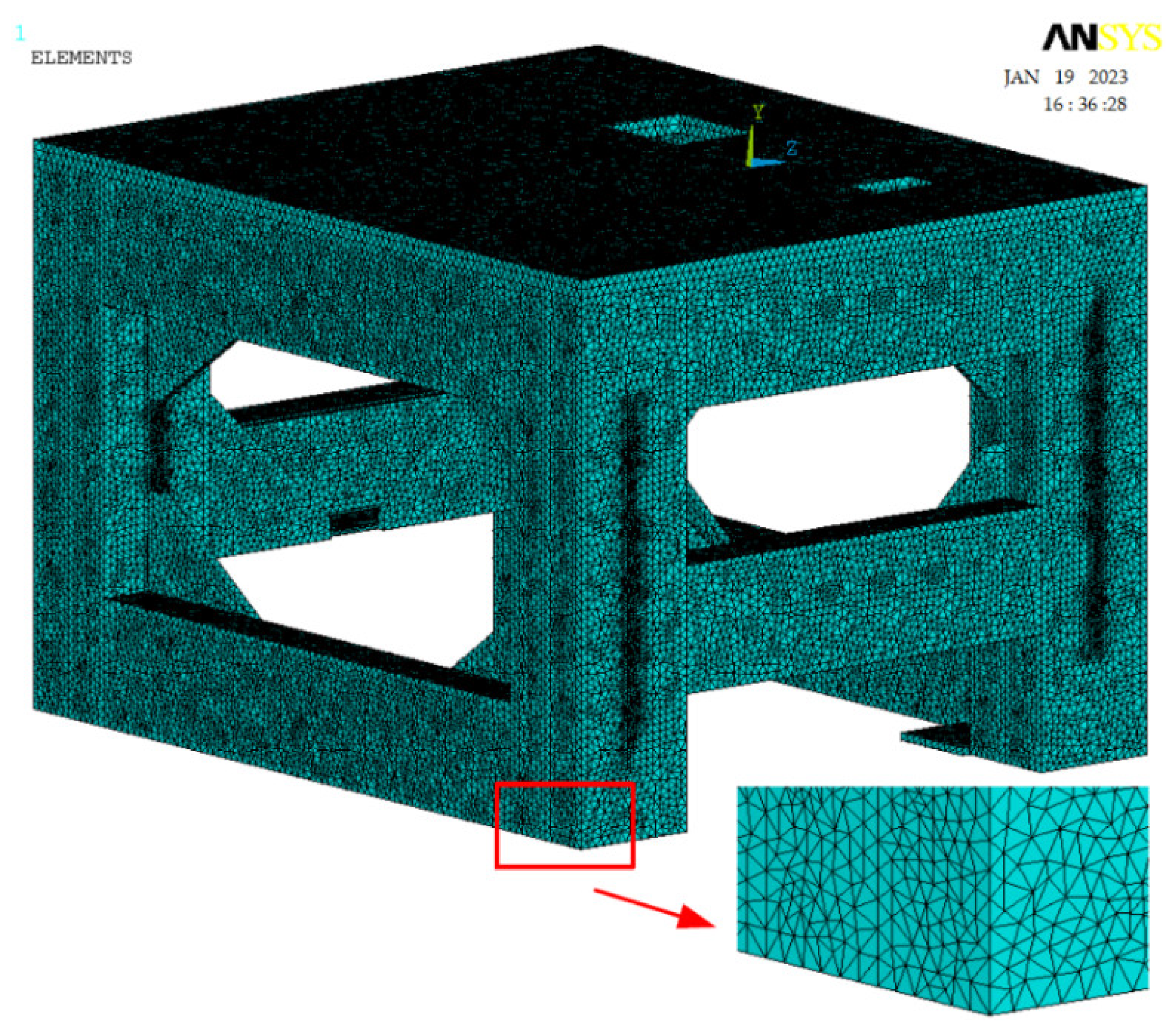
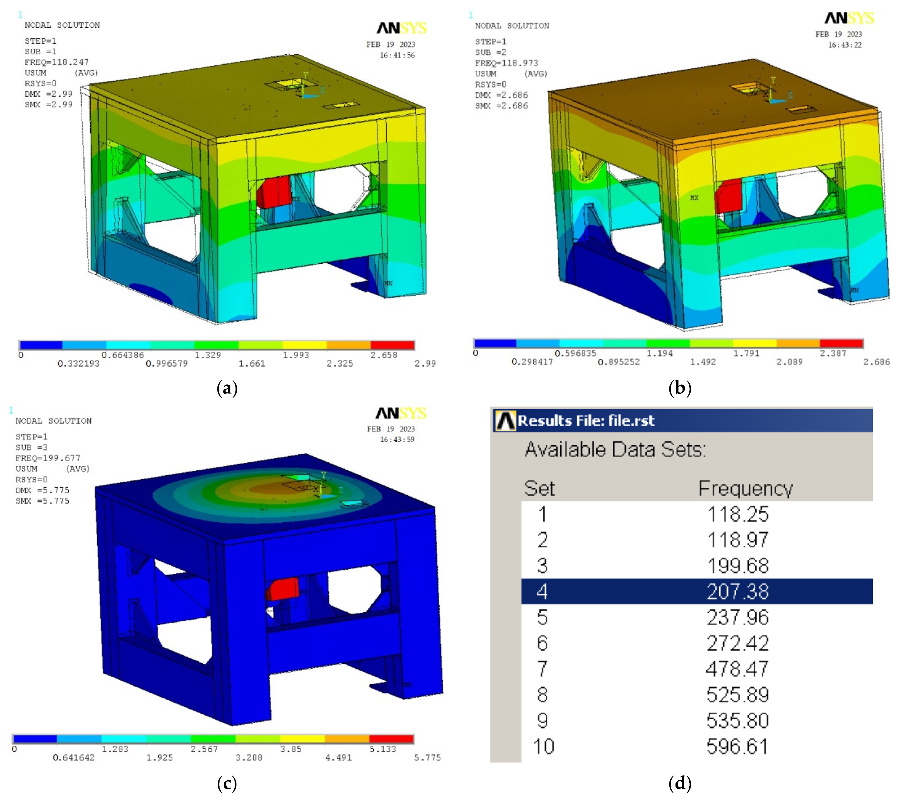
2.2. The Dynamic Analysis in the Design of a Fatigue Testing Device for Combined Torsion and Bending

In addition to the results published in previous studies [2,7,8], the design of the testing device for determining the fatigue life of the E3-kolka vehicle frame was also approached considering its fundamental dynamic properties, specifically the natural frequencies. The values of the natural frequencies are obtained analytically by solving the homogeneous differential equation of motion without a right-hand side and with homogeneous boundary conditions. From a mechanical perspective, this represents the problem of undamped free vibration, which can be described by Equation (3) [29]:
M u ¨ t + K u t = 0
with a solution given by Equation (4):
u t = y sin ω 0 t .
By calculating ü and substituting it into (3), the basic equation for solving undamped free vibration can be obtained (5):
ω 0 2 M + K y = 0 .
From a mathematical perspective, Equation (5) represents an eigenvalue problem for matrices M and K. For Equation (5) to have non-trivial solutions, it is necessary to fulfill condition (6):
det K ω 0 2 M = 0 .
If the dimension of matrices M and K is “n × n”, it is possible to calculate n eigen circular frequencies ωi and n eigen shapes yi. The eigenfrequencies are arranged in ascending order ω1ω2 ≤ … ≤ ωn. By assembling the vectors yi into a modal matrix V (with yi forming a column of the modal matrix) and the squares of eigenfrequencies into a diagonal spectral matrix Ω, all solutions of Equation (5) can be summarized in a single Equation (7):
K ω 0 2 M V = 0 .
Equation (7) is the fundamental state equation for FEM models. The problem of eigenvalues and eigenvectors is a standard feature in software packages like ANSYS. It is crucial to determine the eigenfrequencies and their corresponding eigenmodes of the analyzed frame, especially when evaluating the behavior of a time-varying, force-loaded object with significant harmonic components. The key objective is to ensure that the excitation frequencies and the natural frequencies of the system are either different or sufficiently separated. Otherwise, the system will exhibit self-excited vibrations, characterized by the phenomenon known as resonance. Resonance is unacceptable in operation as it often leads to malfunctioning and subsequent structural failure. From a mathematical perspective, computing eigenfrequencies and eigen shapes is one of the fundamental tasks of numerical mathematics [30].
Based on the aforementioned facts, an important aspect in the structural design of the testing device for measuring the fatigue life of materials is the design of appropriate profiles for the supporting component, namely the frame. According to [8], the frame will be subjected to cyclic motion generated by eccentric components driven by an electric motor equipped with a frequency converter ranging from 0 to 100 Hz. Therefore, it is crucial to design a robust frame capable of withstanding all frequencies within this range. It has been determined that the lowest natural (resonant) frequency of the frame should be approximately 1.2 times the excitation frequency (100 Hz). The solution involves creating a FEM computational model using ANSYS software. Through a series of re-analyses, the desired parameters of the frame will be determined. These FE analyses have been performed for FE meshes with the elements size of 12 mm to 2 mm. As an optimal FE mesh, the element size of 5 mm has been considered sufficient. In principle, this approach represents experimental ways to determine an optimal element size together with verifying its suitability. In this process, the weight of the frame was of secondary importance. Figure 5 illustrates the finite element model of the frame, which was constructed using tetrahedral elements with four nodes. All components of the device, including motors, were modeled as mass points to accurately represent their spatial distribution (Figure 6). Parameters of the experimental device are introduced in Table 1.

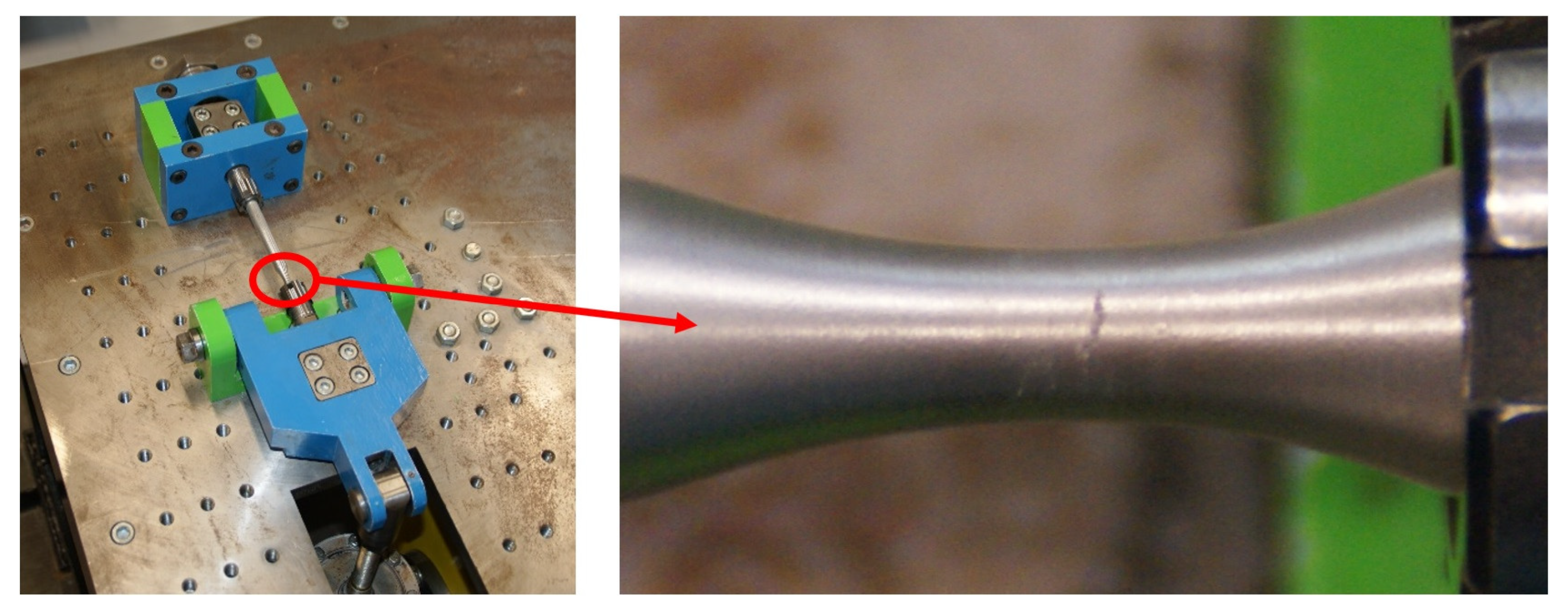
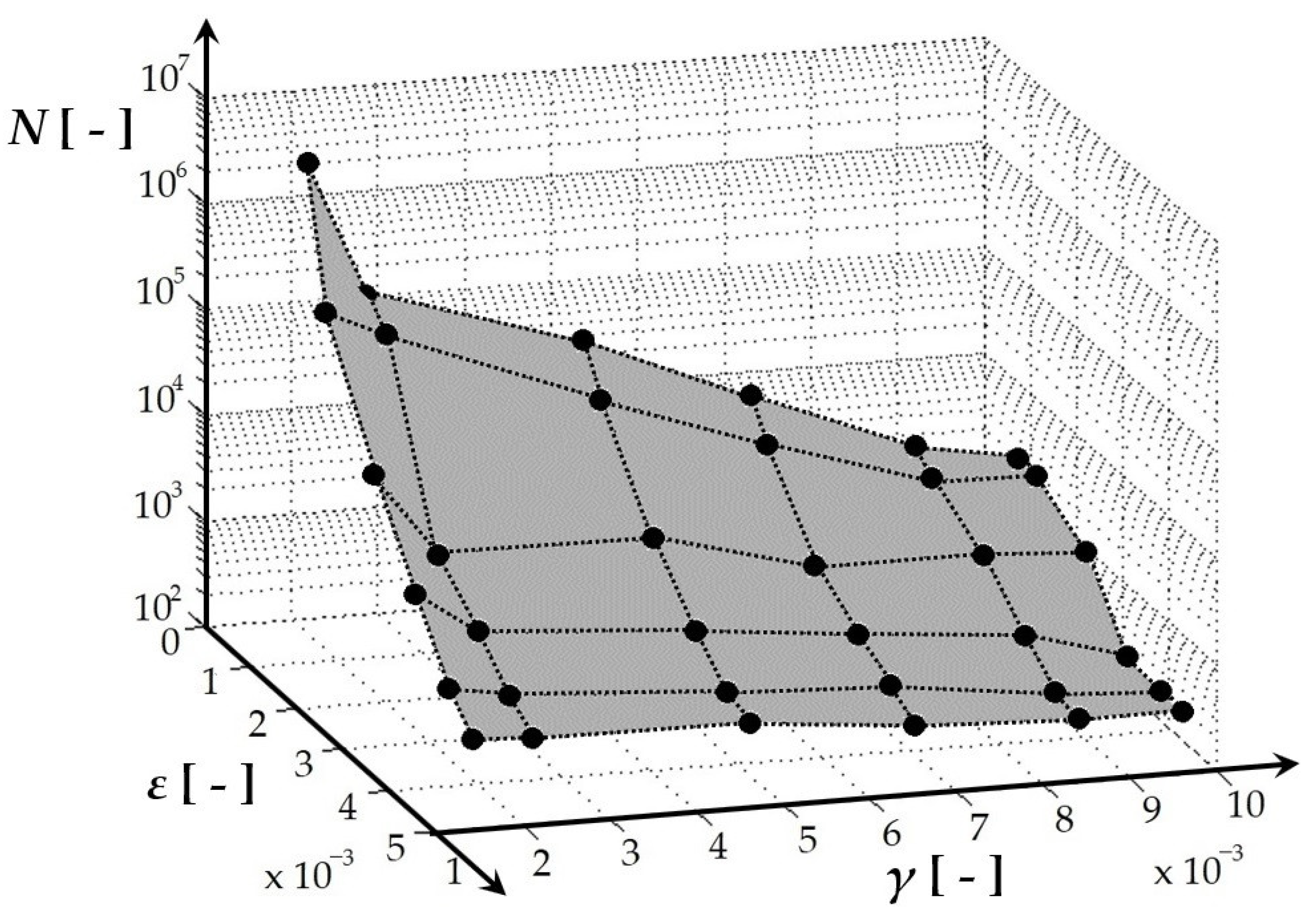
2.3. Methodology for Measuring the Fatigue Life of the Structural Material of a Vehicle Frame

The fatigue life of the vehicle frame material was measured under multiaxial loading conditions (Figure 7) using the specifically designed testing device. The measurement methodology was extensively described in [2,7,8,25]. The validity of the measurement results obtained from the testing device was verified by comparing them with the results obtained from low cycle fatigue criteria, including B-M, F-S, Liu I and II, and SWT, using the Fatigue Calculator software. Table 2 provides a summary of all the important measurement parameters.

2.4. Dynamic Simulation of a Designed Vehicle’s Driving

Figure 8 illustrates the comparison between the operating principles of the standard steering system and the newly designed steering system. These figures present virtual models of tricycles created using SIMPACK software. In Figure 8a, a three-wheeled vehicle is depicted in the standard delta configuration with front-wheel steering while navigating a left-hand turn. Figure 8b showcases the model of the proposed E3-kolka equipped with a novel front-wheel steering system. It is observed that the suspension system of the E3-kolka fork allows it to lean towards the outer side of the traversed curve, aligning with the centrifugal force direction.
The SIMPACK software enables the modeling and analysis of diverse vehicle types, including various tire–road contact models. To achieve a highly accurate virtual representation of the real-world scenario, CAD models of each component in both versions of the tricycle were generated. These models serve as the basis for deriving essential mass and inertia parameters crucial for dynamic analysis. As illustrated in the figures, the dynamic analysis also considers the influence of the driver.
After creating dynamic vehicle models, it became possible to accurately determine the total weight (vehicle + driver = 281.5 kg), inertia parameters, and the position of the center of gravity for precise analytical calculations. Figure 9 visually presents a schematic view of the aforementioned three-wheeled vehicles, featuring two rear wheels, as observed from both top and rear perspectives. The O axis represents the tilt axis of the vehicle during left-hand turns. It is worth noting that the newly designed steering system allows for a flexible configuration of the front wheel. In the most extreme scenario observed in the physical vehicle, depicted in Figure 9b, maximum steering wheel rotation was employed to achieve this configuration. As a result, the vehicle follows a circular path with a radius of 1.5 m.
The investigation of driving characteristics focuses primarily on evaluating variables that influence the improvement of the driving stability of the E3-kolka. Therefore, a specific driving maneuver has been chosen, involving driving in a counter-directional S curve with a relatively small radius of R = 1.5 m.
After conducting a series of driving analyses at various speeds, the critical speed at which both vehicles experience stability failure, particularly in terms of rollover, was determined. The evaluative comparison criterion was defined as the magnitude of the force acting on the contact point of the rear inner wheel (which is unloaded during the curve). The critical case represents a force value of zero. Analytical calculations presented in [8] revealed that the stability of both three-wheeled vehicles is independent of their weight. The crucial parameters are the position of the center of gravity and the design parameters of both vehicles, including the wheelbase and track width. The construction parameters of the actual vehicle used in the simulations were as follows: a vehicle wheelbase of L = 1.3 m and a rear wheel track width of B = 0.727 m. The position of the center of gravity is determined by two parameters: its height above the road surface (h = 0.5279 m) and the distance from the front wheel (lF = 0.85 m). These parameters apply to both versions of the simulated three-wheeled vehicle. The parameters of the E3-kolka vehicle are listed in Table 3.

3. Results

This section presents further results derived from the development of the innovative E3-kolka, the unconventional vehicle. The results encompass two key areas:
  • Experimental domain:
  • Pertinent details regarding the design of the testing device used to measure the fatigue life of materials;
  • Measurements of the fatigue life of the frame material employed in the proposed vehicle;
  • Theoretical domain:
  • Insights into potential structural modifications aimed at enhancing the vehicle’s roadworthiness;
  • Numerical results comparing the effect of the suspension mechanism of the front steering wheel in both conventional and non-conventional designs.

3.1. Vehicle Design Modification to Fulfil Roadworthiness

By substituting the corresponding values into Equation (1), it was found that a force of Fmax = 331.5 N is necessary to turn the steering wheel. This value surpasses the limit specified by regulation [28]. The current steering system of the E3-kolka employs a gear ratio of ik = 3 achieved through a set of spur gears (Figure 4a) [2,7,8,19]. If this gear ratio is eliminated, the moment applied to the steering axis will triple, i.e.,
M max = M v i k = 58 3 = 174   Nm .
The required value of the gear ratio can be determined using Equations (1) and (2) as follows:
i p 2 M max D v F max = 2 174 0.35 250 = 3.98 .
To enhance safety and ensure that the force exerted on the steering wheel remains significantly below the 250 N threshold, it is essential to integrate a transmission system with a gear ratio of ip = 5 (-) into the system. Subsequently, by employing Equations (1) and (2), the precise force value exerted on the steering wheel can be determined as follows:
F = 2 M max D v i p = 2 174 0.35 5 = 199   N .
The conducted calculation represents the scenario if the structural modification according to Figure 4c was chosen.

3.2. Research Findings on Dynamic Characteristics of a Fatigue Testing Device

The results of the analyses, specifically the first three natural frequencies and their corresponding mode shapes, are presented in Figure 10a–c. Figure 10d provides additional quantifications of the natural frequencies. The lowest natural frequency of the frame design presented is 118 Hz, which meets the requirement of 1.2 times the natural frequency.
The frame is robust and can serve as a supportive structure for the testing device, enabling the experimental determination of fatigue characteristics. Currently, the testing device provides a significant volume of valuable data concerning the fatigue life of diverse materials [7,8,11,25].
We performed a total of six sets of analyses (Table 4) of the dimensions of the tetrahedral linear mesh in the range of 2–12 mm to determine the sensitivity to the change in the size of the mesh (Figure 11). The goal was to choose the appropriate size of the network in terms of the accuracy of the results achieved, but also the difficulty in terms of the value of the computing time.
From the point of view of the obtained first three natural frequencies, we reached the following conclusions. In the case of the first natural frequency, the frequency increases when the elements are enlarged. This is 0.95 Hz/mm between 2–5 mm and 0.97 Hz/mm between 5–12 mm. This change is acceptable in the case of such mesh size ranges and constitutes a total increase in natural frequency of approx. 0.83%/1 mm of the mesh, i.e., the difference between 2 mm and 12 mm is an increase of 8.3%. This difference is generally acceptable, considering the deviations caused by the real distribution of the weights of the additional devices and the clamping of the device.
In our case, the time required for the calculation of the task was also an important evaluation parameter for the selection, which is shown in the graph, where you can see that from the value of 5 mm, there is a significant increase in the size of the task. And that between 5 mm and 2 mm 6.6 times and between 5 mm and 3.5 mm twice. Therefore, we chose the size of 5 mm as the resulting mesh, where the computational complexity is 6.6 times smaller and the difference from the 2 mm mesh is 2.85%.

3.3. Research Findings on Multiaxial Fatigue Life Measurement of Structural Material in Vehicle Frame

The fatigue life measurement was conducted using the experimental device shown in Figure 3, Figure 6, Figure 7, and Figure 10, following the methodology outlined in [7,8,11,19,25] and utilizing the parameters specified in Section 2.3. Figure 12 depicts the spatial relationship derived from multiaxial fatigue life measurements, considering the combined effects of bending (deformation ε) and torsion (deformation gamma) at various load levels for the welded material EN AW 6063 (used in the E3-kolka frame). The phase shift between bending and torsional loads was set at φ = 0°. A notable inverse correlation is observed between the decreasing tendency of the number of cycles to fail and the increase in either loading mode. Similarly, Figure 13 presents a comparable graph, highlighting the results of multiaxial fatigue life measurements for the base material EN AW 6063 (used in the E3-kolka frame) under combined bending (deformation epsilon) and torsion (deformation gamma) at different load levels, also with a phase shift of φ = 0°. By comparing Figure 12 and Figure 13, it becomes apparent that lower deformation amplitudes result in slightly higher fatigue life for the welded material. Detailed numerical measurement values were published in [8].
In the case of a 90° phase shift between the loads (Figure 14 and Figure 15), a similar trend was observed, where combinations of small deformation amplitudes resulted in higher fatigue life for the welded samples. By comparing the results in terms of the influence of the phase shift φ, it was noted that there is a slight increase in fatigue life with a 90° phase shift.

3.4. Research Findings on Dynamic Simulations of a Designed Vehicle’s Driving

The article [31] analyzed the maximum vehicle speed analytically as a function of the curve radius. This section presents the results obtained for the same configurations using numerical simulation in the SIMPACK program. The numerical analysis outputs are presented in Figure 16 and Figure 17. These figures illustrate the simulation results for a three-wheeled vehicle with standard steering (Figure 16) and the E3-kolka (Figure 17). Additionally, the figures provide visual representations and values of the vertical wheel forces at the contact patch in the curve for the unladen wheel and the road surface.
By comparing the results of the analytical calculation with those of the numerical analyses, it can be concluded that the maximum driving speed for stability against rollover of the three-wheeled vehicle is accurately determined (Table 5). The small discrepancies are due to the fact that during the maneuver in the curve, the passenger’s body, in the case of numerical simulations, undergoes lateral movement caused by the centripetal acceleration. As a result, the overall center of gravity of the vehicle–driver system also shifts in the same direction.
By comparing the results presented in Figure 16 and Figure 17, it is evident that the suggested steering solution significantly improves the stability of the E3-kolka in curves. The validity of this claim is supported by the observed pattern of the vertical wheel force at the contact patch between the unladen wheel and the road surface during curve traversal. The consistently high values of the vertical wheel force for the unladen wheel throughout the entire simulated maneuver provide further evidence of reliable and secure vehicle control in terms of mitigating the risk of rollover (Figure 17).
Figure 18 presents the simulation results for the driving stability of both a three-wheeled vehicle with standard steering (Figure 18a) and the E3-kolka (Figure 18b) in the graphical interface of the SIMPACK program. Analyzing the numerical data obtained from Figure 16, Figure 17, and Figure 18, it is evident that when driving at the identical velocity of v = 10.685 km/h through a curve with a radius of Rz = 1.5 m, the three-wheeled vehicle equipped with standard steering loses stability and experiences rollover. However, E3-kolka maintains continuous contact between its rear inner wheel and the road surface.

4. Discussion

The mechanism of the E3-kolka can be defined as a system designed to enhance stability and prevent rollover of three-wheeled vehicles during cornering, based on a mechanical principle. However, its design encountered challenges, which were addressed in previous works [2,7,8,19]. With each subsequent modification, it has been necessary to validate the theoretical effectiveness of improving the current state. As evidenced by the research conducted so far, this issue of designing an unconventional vehicle and ensuring its operational viability for commercial use is highly complex. It is important to note that no vehicle can be considered suitable unless its roadworthiness complies with the specific regulations of each country.
As mentioned earlier, the maximum allowable force applied to the vehicle’s steering wheel is 250 N within specific boundary conditions. This issue was addressed under static vehicle conditions, during which steering was identified as the most strenuous task. Measurement results revealed that the E3-kolka system failed to meet this requirement, with a force of 331.5 N exceeding the limit of 250 N. Consequently, this article presents design modifications aimed at resolving this problem. In analyzing the current state of the matter, it was observed that there is a lack of theoretical studies discussing nonconventional steering mechanisms for three-wheeled delta-configured vehicles. The closest relevant work [32] explores the tadpole configuration in comparison to the delta configuration of the E3-kolka.
The proposed mechanism enables differential steering of the front wheels, allowing for varying radii in curves. However, it lacks the capability for wheel tilt and displacement, which is present in the E3-kolka. Additionally, the vehicle frame of the proposed mechanism is tubular with a circular cross-section, while the E3-kolka features a shaped profile. In the study [10], a delta-configured three-wheeled vehicle is discussed; however, the proposed mechanism does not allow for the articulated movement of the steered wheel, like the E3-kolka. Moreover, the study does not provide calculations or information regarding the required steering force on the steering wheel. Some of the analyzed works share a common feature of electronically controlled tilting mechanisms [13,14].
Other analyzed works often address the issue of steering forces in applications for four-wheeled vehicles [33] or focus on the design of electronically controlled power steering [34]. In contrast, the E3-kolka system operates exclusively on a mechanical principle. This is the main advantage of the E3-kolka system compared to the analyzed solutions mentioned in the literature. The necessary design modification, in terms of complying with the legislation of the country where the vehicle will be sold, is relatively simple: implementing a planetary gearbox into the vehicle’s steering system.
Based on the design modification depicted in Figure 4b, it is evident that this alteration will impose considerable constraints on the rotation of the steering console. Consequently, the maximum steering angle of the front wheel will be diminished during left turns, leading to an asymmetry in the wheel’s range of motion. Therefore, this solution cannot be considered suitable.
The variant shown in Figure 4c eliminates the possibility of using the current front gear mechanism. As a result, there is a requirement to incorporate a transmission that can reverse the direction of rotation. A bevel gear serves as a suitable additional component to the gearbox.
The advantage of the variant with the gearbox mounted under the steering wheel (Figure 4d) is the reduced number of required cardan shafts. However, it is important to note that in each of the mentioned variants, a gearbox bracket needs to be manufactured and securely attached to the vehicle frame. This modification can be considered minor in terms of the existing frame structure of the vehicle (Figure 2b). Based on the aforementioned findings, the last design appears to be the most suitable option. It does not restrict the range of motion of the steering console (in comparison to the first design) and does not necessitate any additional supplementary components (in comparison to the second design). An appropriate gearbox, for instance, is available from the manufacturer PHT VERTEX PRECISION Components Corporation.
From a safety perspective, this study also provides information on the lifespan research of the vehicle frame material. It is desirable to have various devices available for investigating the fatigue life of materials subjected to both uniaxial and multiaxial loading. These devices are often commercially manufactured, but there are also cases where proposed designs are tailored to specific workplace requirements [35,36,37,38].
The construction of testing devices is currently well-managed. However, a challenge arises when retrieving experimental results from fatigue life measurements of specific tested materials for direct implementation in one’s research. Therefore, the proposed testing device (Figure 3) makes a valuable contribution to the field of fatigue life measurements of materials. It provides relevant results for further applied research in the workplace. This study, along with [7,8,19,25], offers comprehensive technical information on the operational principle, safety, reliability, measurement methodology, construction, and verification of the testing device. Based on the measurement results obtained from the testing device (Figure 12, Figure 13, Figure 14 and Figure 15), it was determined that the tested material has a satisfactory lifespan for constructing a non-conventional means of transportation at relatively low costs (although there are more expensive and stronger aluminum alloys available for achieving a lightweight design). The measurement results were discussed in [7,8], while Figure 12, Figure 13, Figure 14 and Figure 15 provide an additional interpretation of the results in the form of 3D graphs. These graphs simplify the demonstration of the fatigue life cycle comparison between the base material and the welded material EN AW6063 under combined loading of bending and torsion.
As mentioned earlier, three-wheeled vehicles have specific characteristics compared to their four-wheeled counterparts. When it comes to the delta arrangement, the drawbacks of this three-wheeled configuration become apparent during cornering. To address these issues, a front-wheel steering system was developed to mitigate the limitations of the delta arrangement. The effectiveness of this steering system was validated through analytical calculations, which demonstrated that the displacement of the front wheel in the three-wheeled vehicle equipped with the newly designed steering system contributes to enhanced stability. Additionally, multibody vehicle models were created, incorporating both the standard steering system and the newly designed one, to conduct simulation calculations that provide more realistic results. These dynamic vehicle models, implemented in the SIMPACK program, enabled comprehensive evaluation of the driving characteristics of both three-wheeled vehicles—those equipped with the standard steering system and those with the newly designed steering system. The comparisons presented in Table 2 indicate that the newly designed steering system fulfills its purpose by enhancing stability and, consequently, improving driving safety compared to the conventional front-wheel suspension system. Moreover, it was observed that simulation programs provide more accurate results than analytical calculations, primarily due to their ability to account for the dynamic effects of vehicle components and passengers, a practical limitation in analytical calculations.
Based on an analysis of the current state of the issue, it can be concluded that there are technical solutions aimed at enhancing the safety of three-wheeled vehicles. However, these systems employ different steering and front-wheel suspension methods to achieve this objective. An illustrative example of such a solution involves the utilization of an actuator with a servo motor to actively tilt the vehicle frame [39], effectively mitigating the effects of centrifugal forces during cornering. This system has undergone testing on an electric vehicle, albeit one with a shorter wheelbase and narrower track width, commonly referred to as a “narrow vehicle.”
An intriguing study is presented in the paper by [40]. The author explores the use of engine torque to improve driving safety and prevent rollovers by effectively distributing it among the wheels. The system incorporates a controller that mitigates the negative effects of cornering when combined with a braking threshold or encountering road irregularities. However, it is important to note that in this case, the utilization does not involve a front-wheel steering system.
The research paper [41] presents a modification to the front-wheel steering system. The authors propose an actively controlled system for steering the front wheels. This system aims to actively manage the weight distribution and its impact to improve the safety of three-wheeled vehicles while cornering. Once again, this modification involves the implementation of a complex mechatronic system.
In the article [42], the researchers introduce a method aimed at enhancing the maneuverability and tilt control of a three-wheeled vehicle. The authors present a direct tilt control system that relies on an active steering amplification curve. Although the proposed design signifies a notable advancement in tilt control and effectively reduces perceived lateral acceleration, further experimental examination of the system is necessary under diverse operating conditions.
Similarly, other proposals for steering systems in delta-type three-wheeled vehicles employ electronic or mechatronic systems to improve rollover stability [43,44,45]. However, a disadvantage of these systems is their dependence on additional components. In contrast, the newly proposed steering system presented by the authors operates solely on a mechanical principle. This implies that operating costs, energy consumption, maintenance expenses, and similar factors are eliminated. As evident from the presented results and analyses, the system demonstrates significant potential for future applications in delta-type three-wheeled vehicles.

5. Conclusions

During the process of addressing the utilization of dynamic analysis in the complex design of an unconventional three-wheeled vehicle aimed at improving safety during cornering, the following proposals have been put forward:
  • Three alternative design solutions were presented to ensure compliance with the maximum steering force requirement on the steering wheel (below 250 N) and facilitate the selection of the optimal solution;
  • The structurally robust frame was developed for a fatigue life testing device, which underwent dynamic analysis to ensure safety;
  • The original methodology for measuring multiaxial fatigue life was summarized;
  • Dynamic models were created for both conventional and unconventional vehicles, incorporating parameters that correspond to real-world conditions;
  • The vehicle design, featuring a patented front-wheel suspension system, exerts a significant influence on safety and ride comfort;
  • The proposed vehicle meets the legislative requirements for roadworthiness in Slovakia;
  • The safety of the proposed vehicle’s frame is guaranteed in terms of its fatigue life;
  • The proposed vehicle enhances the maximum safe cornering speed compared to conventional three-wheeled vehicles;
  • Most importantly, the achievement of all the aforementioned findings is based on a more cost-effective mechanical principle.

Author Contributions

Conceptualization, M.B., J.D. and M.S.; methodology, M.B., D.M. and A.S.; software, M.B., J.D. and M.S.; validation, M.B., J.D. and A.S.; formal analysis, M.B., J.D., M.S. and D.M.; investigation, M.B. and J.D.; resources, M.B., J.D. and D.M.; data curation, M.B., J.D. and M.S.; writing—original draft preparation, M.B., J.D. and D.M.; writing—review and editing, M.S. and A.S.; visualization, M.B. and J.D.; supervision, M.S. and A.S.; project administration, J.D. and M.S.; funding acquisition, J.D. and M.S. All authors have read and agreed to the published version of the manuscript.

Funding

This research was supported by the project KEGA 031ŽU-4/2023: Development of key competencies of the graduate of the study program Vehicles and Engines and by the project VEGA No. 1/0423/23.

Data Availability Statement

Not applicable.

Conflicts of Interest

The authors declare no conflict of interest.

References

  1. UV 3984, SK. Available online: https://wbr.indprop.gov.sk/WebRegistre/UzitkovyVzor/?lang=en (accessed on 15 May 2023).
  2. Blatnický, M.; Sága, M.; Dižo, J.; Bruna, M. Application of light metal alloy EN AW 6063 to vehicle frame construction with an innovative steering mechanism. Materials 2020, 13, 817. [Google Scholar] [CrossRef] [PubMed]
  3. National Highway Traffic Safety Administration. Available online: http://www.yasa.org/upload/uploadedfiles/IPTRolloverMitigationReport.pdf (accessed on 5 June 2023).
  4. Chen, C.F. Personality, safety attitudes and risky driving behaviours-Evidence from young Taiwanese motorcyclists. Accid. Anal. Prev. 2009, 41, 963–968. [Google Scholar] [CrossRef] [PubMed]
  5. Forkenbrock, G.J.; Garrott, W.R.; Heitz, M.; O’Harra, B.C. An experimental examination of J-turn and fishhook maneuvers that may induce on-road, untripped, light vehicle rollover. J. Passeng. Car: Mech. Syst. J. 2003, 112, 1112–1127. [Google Scholar]
  6. Gawade, T.; Mukherjee, S.; Mohan, D. Rollover propensity of three-wheel scooter taxis. SAE Tech. Pap. Ser. 2004. [Google Scholar] [CrossRef]
  7. Blatnicky, M.; Dizo, J.; Molnar, D.; Suchanek, A. Comprehensive analysis of a tricycle structure with a steering system for improvement of driving properties while cornering. Materials 2022, 15, 8974. [Google Scholar] [CrossRef]
  8. Blatnický, M.; Dižo, J.; Sága, M.; Brůna, M.; Vaško, M. Experimental research on Manson-Coffin curves for the frame material of an unconventional vehicle. Materials 2022, 15, 1768. [Google Scholar] [CrossRef]
  9. Moravec, J.; Kopas, P.; Jakubovicova, L.; Leitner, B. Experimental casting of forging ingots from model material. In Proceedings of the 22nd Slovak-Polish Scientific Conference on Machine Modelling and Simulation MMS, Sklene Teplice, Slovakia, 5–8 September 2017. [Google Scholar]
  10. Spânu, A.; Stoenescu, F.; Lorenzi, M.; Avram, M. Analysis of three wheeled electric vehicle with increased stability on the road. In Proceedings of the 8th International Conference on Advanced Concepts in Mechanical Engineering ACME, Iasi, Romania, 7–8 June 2018. [Google Scholar]
  11. Ataei, M.; Khajepour, A.; Jeon, S. Development of a novel general reconfigurable vehicle dynamics model. Mech. Mach. Theory 2021, 156, 104147. [Google Scholar] [CrossRef]
  12. Kidane, S.; Rajamani, R.; Lee, A.; Starr, P.J.; Donath, M. Development and experimental evaluation of a tilt stability control system for narrow commuter vehicles. IEEE Trans. Control. Syst. Technol. 2010, 18, 1266–1279. [Google Scholar] [CrossRef]
  13. Sindha, J.; Chakraborty, B.; Chakravarty, D. Rigid body modelling of three-wheel vehicle to determine the dynamic stability—A practical approach. In Proceedings of the IEEE International Transportation Electrification Conference ITEC, Chennai, India, 27–29 August 2015. [Google Scholar]
  14. Barker, M.; Drew, B.; Darling, J.; Edge, K.A.; Owen, G.A. Steady-state steering of a tilting three-wheeled vehicle. Veh. Syst. Dyn. 2010, 48, 815–830. [Google Scholar] [CrossRef]
  15. Klimenda, F.; Soukup, J.; Skocilasova, B.; Skocilas, J. Vertical vibration of the vehicle when crossing over transverse speed bumps. Manuf. Technol. 2020, 20, 55–59. [Google Scholar] [CrossRef]
  16. Gerlici, J.; Shakno, V.; Yefymenko, A.; Verbitskii, V.; Kravchenko, A.; Kravchenko, K. The stability analysis of two-wheeled vehicle model. In Proceedings of the 22nd Slovak-Polish Scientific Conference on Machine Modelling and Simulations MMS, Sklene Teplice, Slovakia, 5–8 September 2017. [Google Scholar]
  17. Llopis-Castelló, D.; Camacho-Torregrosa, F.J.; García, A. Analysis of the influence of geometric design consistency on vehicle CO2 emissions. Transp. Res. Part D-Transp. Environ. 2019, 69, 40–50. [Google Scholar] [CrossRef]
  18. Shavelkin, A.; Gerlici, J.; Shvedchykova, I.O.; Kravchenko, K.; Kruhliak, H.V. Management of power consumption in a photovoltaic system with a storage battery connected to the network with multi-zone electricity pricing to supply the local facility own needs. Electr. Eng. Electromechanics 2021, 2, 36–42. [Google Scholar] [CrossRef]
  19. Sága, M.; Blatnický, M.; Vaško, M.; Dižo, J.; Kopas, P.; Gerlici, J. Experimental determination of the Manson-Coffin curves for an original unconventional vehicle frame. Materials 2020, 13, 4675. [Google Scholar] [CrossRef]
  20. Różyło, P. Passive safety of a buggy-type car in the aspect of a dynamic analysis of the frame. Acta Mech. Autom. 2019, 13, 75–79. [Google Scholar] [CrossRef]
  21. Cernohlavek, V.; Svoboda, M.; Sterba, J.; Chalupa, M.; Sapieta, M. Analytical and experimental solution of vibrations of a system of bound bodies. Manuf. Technol. 2020, 20, 699–707. [Google Scholar]
  22. Callens, A.; Bignonnet, A. Fatigue design of welded bicycle frames using a multiaxial criterion. Procedia Eng. 2012, 34, 640–645. [Google Scholar] [CrossRef]
  23. Palanivendhan, M.; Devanand, S.; Chandradass, J.; Philip, J.; Sajith Redd, S. Design and analysis of 3-wheeler chassis. Mater. Today Proc. 2021, 45, 6958–6968. [Google Scholar] [CrossRef]
  24. Xiu, R.; Spiryagin, M.; Wu, Q.; Yang, S.; Liu, Y. Fatigue life prediction for locomotive bogie frames using virtual prototype technique. Proc. Inst. Mech. Eng. Part F J. Rail Rapid Transit 2021, 235, 1122–1131. [Google Scholar] [CrossRef]
  25. Sága, M.; Blatnická, M.; Blatnický, M.; Dižo, J.; Gerlici, J. Research of the fatigue life of welded joints of high strength steel S960 QL created using laser and electron beams. Materials 2020, 13, 2539. [Google Scholar] [CrossRef] [PubMed]
  26. Leitner, B.; Figuli, L. Fatique life prediciton of mechanical structures under stochastic loading. In Proceedings of the 22nd Slovak-Polish Scientific Conference on Machine Modelling and Simulation MMS, Sklene Teplice, Slovakia, 5–8 September 2017. [Google Scholar]
  27. Moravec, J.; Bury, P.; Cernobila, F. Investigation of forging metal specimens of different relative reductions using ultrasonig waves. Materials 2021, 14, 2406. [Google Scholar] [CrossRef]
  28. Ministry of Transport and Construction of the Slovak Republic. Available online: https://www.mindop.sk/en (accessed on 19 April 2023).
  29. Feynman, R.P.; Leighton, R.B.; Sands, M. Feynman’s Lectures on Physics. Available online: https://www.feynmanlectures.caltech.edu/ (accessed on 6 June 2023).
  30. Sága, M.; Vavro, J.; Kopecký, M. Computer Analysis and Synthesis of Mechanical Systems, 1st ed.; ZUSI: Žilina, Slovakia, 2002; pp. 198–250. (In Slovak) [Google Scholar]
  31. Dizo, J.; Barta, D.; Blatnicky, M. Improvement driving characteristics of electric tricycle. In Proceedings of the 17th International Scientific Conference Engineering for Rural Development, Jelgava, Latvia, 23–25 May 2018. [Google Scholar]
  32. Lin, C.-S.; Yu, C.-C.; Ciou, Y.-H.; Wu, Y.-X.; Hsu, C.-H.; Li, Y.-T. Design and analysis of a light electric vehicle. Mech. Sci. 2021, 12, 345–360. [Google Scholar] [CrossRef]
  33. Kobayashi, T.; Katsuyama, E.; Sugiura, H.; Ono, E.; Yamamoto, M. Efficient direct yaw moment control: Tire slip power loss minimization for a four-independent wheel-drive vehicle. Veh. Syst. Dyn. 2017, 56, 719–733. [Google Scholar] [CrossRef]
  34. Li, X.; Zhao, X.P.; Chen, J.; Men, J.L. Controller design for soft-disability remedy of the electric power steering system. Int. J. Automot. Technol. 2009, 10, 497–503. [Google Scholar] [CrossRef]
  35. Karolczuk, A.; Kurek, M.; Łagoda, T. Fatigue life of aluminium alloy 6082 T6 under constant and variable amplitude bending with torsion. J. Theor. Appl. Mech. 2015, 52, 421–430. [Google Scholar] [CrossRef]
  36. Fomin, O.; Gorbunov, M.; Lovska, A.; Gerlici, J.; Kravchenko, K. Dynamics and strength of circular tube open wagons with aluminum foam filled center sills. Materials 2021, 14, 1915. [Google Scholar] [CrossRef]
  37. Fomin, O.; Gorbunov, M.; Gerlici, J.; Vatulia, G.; Lovska, A.; Kravchenko, K. Research into the strength of an open wagon with double sidewalls filled with aluminium foam. Materials 2021, 14, 3420. [Google Scholar] [CrossRef]
  38. Gourdin, C.; Bradaï, S.; Courtin, S.; Le Roux, J.C.; Gardin, C. Equi-biaxial loading effect on austenitic stainless steel fatigue life. Frat. Ed Integrità Strutt. 2017, 38, 170–176. [Google Scholar] [CrossRef]
  39. Karamuk, M.; Alankus, O.B. Development and experimental implementation of active tilt control system using a servo motor actuator for narrow tilting electric vehicle. Energies 2022, 15, 1996. [Google Scholar] [CrossRef]
  40. Rodriguez-Licea, M.-A. On the tripped rollovers and lateral skid in three-wheeled vehicles and their mitigation. Vehicles 2021, 3, 375–376. [Google Scholar] [CrossRef]
  41. Azim, R.A.; Malik, F.M.; ul Haq Syed, W. Rollover mitigation controller development for three-wheeled vehicle using active front steering. Math. Probl. Eng. 2015, 2015, 918429. [Google Scholar] [CrossRef]
  42. Dandiwala, A.; Chakraborty, B.; Chakravarty, D.; Sindha, J. Vehicle dynamics and active rollover stability control of an electric narrow three-wheeled vehicle: A review and concern towards improvement. Veh. Syst. Dyn. 2022, 61, 399–422. [Google Scholar] [CrossRef]
  43. Rodríguez-Licea, M.A. Robust lateral and longitudinal stability control for delta three-wheeled vehicles with suspension system. Int. J. Veh. Des. 2022, 87, 49–72. [Google Scholar] [CrossRef]
  44. Antony, J.J.; Jayabal, K. Rollover dynamics of a narrow tilting three-wheeled vehicle. In Proceedings of the International Conference on Mechanical, Manufacturing, Modeling and Mechatronics, Kuala Lumpur, Malaysia, 27–29 February 2016. [Google Scholar]
  45. Ketemaw, D.; Seid, S. Design of a rollover index-based sliding mode controller for roll stability of three wheeled vehicles using rear differential braking. Front. Mech. Eng. 2022, 8, 1038289. [Google Scholar] [CrossRef]
Figure 1. The project E3-kolka: (a) Three-wheeled vehicle with enhanced rollover safety during cornering (E3-kolka); (b) Range of motion of the front steered wheel of the E3-kolka.
Machines 11 00842 g001
Figure 2. Comparison of CAD models of welded frames: (a) Steel—Kyburz Classic; (b) Aluminum alloy—proposed vehicle.
Machines 11 00842 g002
Figure 3. Multiaxial fatigue testing system for combined loading in bending and torsion.
Machines 11 00842 g003
Figure 4. Placement options of the auxiliary planetary gearbox: (a) Original steering mechanism (without an additional planetary gearbox); (b) Wit h the planetary gearbox positioned above the small gearwheel; (c) With the planetary gearbox positioned above the steering mechanism; (d) With the planetary gearbox positioned below the steering wheel.
Machines 11 00842 g004aMachines 11 00842 g004b
Figure 5. The FEM model of the frame in the experimental device used for measuring the fatigue properties of materials, along with a detail of the mesh composed of tetrahedral elements.
Machines 11 00842 g005
Figure 6. The 3D CAD model of the experimental device for measuring the fatigue characteristics of materials in combined bending and torsion: (a) The model with the top plate steel; (b) The model without the top plate for better visualization of the arrangement.
Machines 11 00842 g006
Figure 7. Experimental measurement of fatigue of EN AW 6063 material.
Machines 11 00842 g007
Figure 8. Comparison of the driving of a three-wheeled electric vehicle in a curve: (a) With the standard steering system; (b) The newly designed steering system.
Machines 11 00842 g008
Figure 9. Calculations schemes: (a) Scheme of a three-wheeled vehicle with a standard steering system; (b) Scheme of a three-wheeled vehicle with a newly designed steering system.
Machines 11 00842 g009
Figure 10. Custom shape of the frame determined by simulation in Ansys software corresponding to: (a) The first natural frequency; (b) The second natural frequency; (c) The third natural frequency; (d) Values of additional natural frequencies.
Machines 11 00842 g010
Figure 11. Dependence of the calculation sensitivity on the finite element size.
Machines 11 00842 g011
Figure 12. Spatial representation of the fatigue load curve in bending and torsion at various load levels of welded material EN AW 6063 with a phase shift of φ = 0°.
Machines 11 00842 g012
Figure 13. Spatial representation of the fatigue load curve in bending and torsion at various load levels of base material EN AW6063 with a phase shift of φ = 0°.
Machines 11 00842 g013
Figure 14. Spatial representation of the fatigue load curve in bending and torsion at various load levels of welded material EN AW 6063 with a phase shift of φ = 90°.
Machines 11 00842 g014
Figure 15. Spatial representation of the fatigue load curve in bending and torsion at various load levels of base material EN AW6063 with a phase shift of φ = 90°.
Machines 11 00842 g015
Figure 16. Results of numerical analyses of a tricycle with a standard steering system.
Machines 11 00842 g016
Figure 17. Results of numerical analyses of the E3-kolka.
Machines 11 00842 g017
Figure 18. Graphic comparison of the stability of a tricycle: (a) With a standard steering system; (b) With a newly designed steering system.
Machines 11 00842 g018
Table 1. Parameters of the experimental testing device.
Dimensions of a Specimen Unit
Length150mm
Diameter10mm
Parameters of the torsion load
Synchronous servomotor SEW-EURODRIVE CFM71M
Max. static torque6.5Nm
Overload capacity3.3-
Revolutions0 to 6000min−1
Max. loading frequency100Hz
Parameters of the bending load
Synchronous servomotor SEW-EURODRIVE CFM90S
Max. static moment11Nm
Overload capacity3.6-
Revolutions0 to 6000min−1
Max. loading frequency100Hz
Table 2. Parameters for the experimental determination of the low cycle fatigue life of the E3-kolka frame material.
Loading methodControlled deformation amplitude (Manson–Coffin)
Type of loadingBending, torsion, and their combination
Deformation range in bending ε0 to 4.3∙10−3 (-)
Deformation range in torsion γ0 to 10∙10−3 (-)
Ranges of equivalent von Mises stress from Bending deformation for base material EN AW 60630 to 220 MPa
Ranges of equivalent von Mises stress from Bending deformation for welded material EN AW 60630 to 46 MPa
Ranges of equivalent von Mises stress from torsional deformation for base material EN AW 60630 to 91 MPa
Ranges of equivalent von Mises stress from torsional deformation for welded material EN AW 60630 to 32 MPa
Loading frequencyf = 30 Hz
Coefficient of cycle asymmetry R = −1R = −1
Phase shift between loadingsφ = 0°, 90°
Table 3. A list of parameters of the E3-kolka vehicle.
ParameterValueUnit
Vehicle base L1.300m
Rear wheel track width B0.727m
CoG from the front wheel lF0.850m
CoG above the road h0.5279m
Total weight mt281.5kg
Curb weight mc151.5kg
Max. weight of a passenger mp130kg
Table 4. Comparison of theoretically obtained maximum speeds of vehicles while driving through curves of selected radii.
Element Size (mm)
23.5571012
Eigenfrequency
(Hz)
1st115.3982117.0407118.2500120.4065123.8831125.0067
2nd116.4068117.8287118.9700120.9625124.0867125.2183
3rd195.5372197.8613199.6800202.9454208.1457210.069
Table 5. Comparison of theoretically obtained maximum speeds of vehicles while driving through curves of selected radii.
Curve Radius
Rc (m)
Maximum Speed of a Conventional Vehicle
(km/h)
Maximum Speed of the E3-kolka
(km/h)
AnalyticallySIMPACKAnalyticallySIMPACK
1.511.10010.68513.69013.263
520.30019.84424.50024.215
1028.66027.70033.83033.100
1535.10034.25840.34039.853
2040.53039.95045.21044.807
2545.30044.79548.80048.003
3049.60047.99051.62050.700
Disclaimer/Publisher’s Note: The statements, opinions and data contained in all publications are solely those of the individual author(s) and contributor(s) and not of MDPI and/or the editor(s). MDPI and/or the editor(s) disclaim responsibility for any injury to people or property resulting from any ideas, methods, instructions or products referred to in the content.

