
Fast Grasping Technique for Differentiated Mobile Phone Frame Based on Visual Guidance
by

Rongli Zhao
1,2, 
Zeren Bao
1,2,
Wanyu Xiao
1,2,
Shangwen Zou
1,2,
Guangxin Zou
1,2,
Yuan Xie
1,2 and
Jiewu Leng
1,2,* 1
State Key Laboratory of Precision Electronic Manufacturing Technology and Equipment, Guangdong University of Technology, Guangzhou 510006, China
2
School of Electromechanical Engineering, Guangdong University of Technology, Guangzhou 510006, China
*
Author to whom correspondence should be addressed.
Machines 2023, 11(7), 689; https://doi.org/10.3390/machines11070689
Submission received: 5 June 2023
/
Revised: 17 June 2023
/
Accepted: 28 June 2023
/
Published: 30 June 2023
(This article belongs to the Special Issue New Trends in Robotics, Automation and Mechatronics)
Abstract
:With the increasing automation of mobile phone assembly, industrial robots are gradually being used in production lines for loading and unloading operations. At present, industrial robots are mainly used in online teaching mode, in which the robot’s movement and path are set by teaching in advance and then repeat the point-to-point operation. This mode of operation is less flexible and requires high professionalism in teaching and offline programming. When positioning and grasping different materials, the adjustment time is long, which affects the efficiency of production changeover. To solve the problem of poor adaptability of loading robots to differentiated products in mobile phone automatic assembly lines, it is necessary to quickly adjust the positioning and grasping of different models of mobile phone middle frames. Therefore, this paper proposes a highly adaptive grasping and positioning method for vision-guided right-angle robots.
1. Introduction
In recent years, the labor-intensive industry of computer, communication, and consumer (3C) products manufacturing has been facing an unprecedented crisis with the transformation and upgrading of the manufacturing industry and the rapid rise in labor costs. The 3C products’ “mechanical replacement” demand is increasingly urgent. As a comprehensive product integrating mechanical, computer, and control technologies, industrial robots have been widely used in various industries with highly integrated mechatronic characteristics. In 3C manufacturing enterprises, industrial robots are mainly used in product assembly and material transportation in the manufacturing process, replacing people to complete product assembly or material handling for processing centers. The three basic elements that must be considered in a robot’s grasping task are localization, the object to be grasped, and its environment [1]. How to perform accurate grasping of the object to be grasped in the grasping environment is a key goal of robotic grasping research. At present, traditional industrial robots are mainly based on online teaching mode [2]. In this mode, the target workpiece needs to be positioned by a fixed fixture first, and the program can only be applied to a single work scenario, which has low efficiency, poor adaptability, and low work flexibility and cannot be quickly adapted to the work tasks of differentiated products.
The smartphone is one of the important 3C electronic products, which has a fast update and is highly detachable. For the hardware modules, smartphones can generally be divided into twelve modules, including the processing chip module, memory module, battery module, wireless communication module, RF module (antenna printed circuit board), display module, camera module, other logic devices (without memory chips), simulators, filters, sensors, printed circuit boards (PCB), and others [3]. Therefore, smartphone assembly manufacturers are faced with a wide variety of parts, complex assembly processes, short beats, and frequent production changes. In the assembly process of mobile phones, the high variability of spare parts leads to the loading and unloading operation method of mobile phone assembly still being mainly manual work, which seriously restricts the production efficiency and the development process of assembly line automation in this industry [4].
In the last decade, emerging industrial applications require robots to identify randomly placed workpieces on conveyors, in stacks, and in pallets faster and more accurately, and the combination of machine vision technology with robotics to help automated systems handle these workpieces has become increasingly widespread in industry [5,6]. Vision-guided robots (VGR) are rapidly becoming a key enabling technology for industrial automation [7]. In view of the problem of numerous smartphone assembly parts and complex assembly processes, this paper takes the middle frame parts in mobile phone assembly as the object and studies the rapid identification positioning and grasping problem when loading and unloading in the process of mobile phone automated assembly. The mid-frame of a mobile phone is an important part supporting the whole mobile phone, and its differentiation mainly lies in the existence of holes with different shapes and specifications, which makes it extremely difficult for the industrial robot to pick up and unload the material for teaching and positioning. To address this problem, this paper integrates machine vision and industrial robots. It proposes the combination of “offline vision analysis of grasping position” and “online vision positioning grasping”, which analyzes the frame image of the mobile phone offline to find the optimal grasping position and then sends the information related to the grasping position to the robot. The robot will then use the online vision to “locate the edge” of the differentiated workpiece, calculate the robot’s picking path and position by combining the obtained information of the picking position, and then realize the robot’s flexible picking of the workpiece.
2. Related Studies
Robots mainly worked in online teaching mode, which lacked the ability of independent judgment and decision-making, before machine vision technology was applied to robotics. In this mode, the robot will only repeat the point-to-point motion according to the movement mode and path set by the instruction. The fixed fixture determines the part position, and the positioning accuracy is determined by the tooling fixture, resulting in low flexibility of the whole application system. In response to the low flexibility of the entire application system, a part of the research has focused on adaptive robot grippers. Sam et al. developed a fixture for different shapes, sizes, and weights based on Bernoulli’s principle to address the problem of non-rigid or semi-rigid food products in the food industry prone to damage during transportation [8]. Liu et al. proposed a non-contact gripper with four Bernoulli heads for different products of different shapes and sizes with irregular rough surfaces and fragile characteristics [9]. Li et al. proposed a non-contact vortex gripper that can be used for gripping silicon wafers in a certain size range by generating a vortex flow to produce an upward lifting force [10]. Maggi et al. proposed an adaptive gripper combining underactuation and vacuum grasping that does not belong to the category of soft grippers but can handle uneven objects made of different materials, including cardboard, glass, sheet metal, and plastic [11]. Xu et al. developed an adaptive two-finger gripper by modifying conventional fin-ray fingers to grasp free-form objects [12]. Although these studies can solve the problem of complex grasping due to item changes to some extent, they do not solve the problem of fixed robot motion trajectories. By introducing a vision guidance system, the robot can break through the limitation that it can only simply repeat the schematic trajectory, enabling it to adjust its motion trajectory in real-time according to the changes in the grabbed workpiece, making it possible to promote production efficiency, improve production quality, and increase the intelligence level of the robot [13].
The first step for a machine vision guided robot for positioning and grasping is to establish the relationship between the image coordinate system of the camera and the coordinate system of the grasping target, realize the unification of coordinate position through camera calibration, and then realize the coordination between the grasping target position and robot position through hand–eye calibration to improve the accuracy of grasping. Then the vision algorithm and image processing are used to describe the target in three dimensions: the recognition and matching of the grabbed workpiece. Finally, the robot grabs the target workpiece according to the recognition and positioning results. Traditional calibration methods include self-calibration methods, active vision methods, and linear calibration methods. [14]. With the continuous progress of technology and hardware levels, calibration methods are constantly updated and calibration accuracy is improving [15]. Yong Zhou et al. [6] proposed and developed a task-oriented markerless hand–eye calibration method based on nonlinear iterative optimization that converts external parameters into variables optimized with a cost function by using error transfer to construct a cost function, making the calibration not only robust to noisy sensors but also able to meet the requirements of task reconstruction accuracy. J.-C. Hsiao et al. [16] proposed a hybrid calibration method to improve the positioning accuracy of industrial robots considering configuration and payload effects. J.-W. Lee et al. [17] proposed a calibration method for industrial robots using Denavit–Hartenberg parameters. Xie et al. [18] developed a new calibration method based on a linear structured optical measurement system to calibrate a six-degree-of-freedom industrial robot, which reduces the complex steps in the calibration process and improves the calibration accuracy by establishing an error model. Gan et al. [19] proposed a calibration method for robot kinematic parameters based on the drawstring displacement sensor, which significantly improves the positioning accuracy of the robot.
Vision-guided robot grasping research has been carried out, and the technology of robot grasping large objects is relatively mature. With the in-depth research of vision-guided algorithms, vision-guided robot grasping methods for fine objects with high accuracy have also been proposed. Fang et al. [20] proposed a small part assembly system using a dual-arm robot for 3C products, where the dual-arm robot achieves position recognition of small parts by deploying a vision system. Huang et al. [21] proposed a distributed grasping strategy and vision guidance method using a Baxter robot to achieve the assembly of pins in 1 mm clearance holes. C. D’Ettorre et al. [22] proposed a vision algorithm for visually guiding a robot to grab a needle in order to avoid the needle handover step and reduce the suture time in response to the situation that the needle needs to switch positions several times when the surgeon performs wound suturing on a patient during surgery. Tao et al. [23] proposed to determine the unique grasping angle using the image mask multiple times subtraction method to guide the robot based on a binocular vision system automatically grabbing scattered self-locking rivets in aircraft assembly.
In the context that smart manufacturing has become the development direction of the world’s manufacturing industry, industrial robots, as an important part of the smart manufacturing system (SMS), influence the level of intelligence of the whole SMS in terms of its automation. Some of the latest technologies in research, such as digital twins (DT), are being applied to the design of industrial robots to improve the intelligence of the entire SMS [24,25]. With DT, engineers can design and commission industrial robots and SMS remotely to reduce costs [26], while enabling rapid configuration of industrial robots, making SMS highly flexible to meet the increasing individual needs of products [27]. In addition, combining machine vision with deep learning and convolutional neural networks to guide robot grasping has become a popular research direction in recent years [28,29]. Andy Zeng [30] from Princeton University proposed a multi-view self-learning vision-guided robot grasping technique that utilizes convolutional neural networks to segment and label different viewpoint target scenes and is highly adaptive with iterative operations associated with multiple vision systems. Williams H.A.M et al. [31] combined machine vision, convolutional neural networks, and robotics to develop a harvesting system for kiwifruit. Luca Bergamini et al. [32] proposed a deep convolutional neural network-based framework to predict the grasping position of a robot when grasping multiple unknown objects using a single RGB image as input. Using a deep convolutional neural network model, Ping et al. [33] proposed a depth image-based vision-guided robotic box-picking system to predict the robot’s grasping position for a texture-free flat object.
Overall, the development of vision-guided robot positioning and grasping technology has matured and is widely used in industries such as automotive assembly, electrical and electronics, 3C manufacturing, industrial agriculture, and handling and palletizing, and it provides strong technical support for safe, reliable, and efficient industrial automation production.
3. Vision-Guided Mobile Phone Frame Grasping System
In the production of a flexible mobile phone assembly line, the production line often needs to change frequently. The vision-guided robot in the traditional mobile phone assembly line only relies on a single online vision image acquisition to complete the analysis and positioning of the hole detection of different models of frames after the production change. The robot needs to re-teach the alignment and grasping position after each production change, which makes the flexibility of the assembly line very low. The vision-guided mobile phone frame grasping system proposed in this study detects and analyzes the distribution of holes in the mobile phone frame by introducing an offline vision system for external operation. The online vision system only collects the local images of the material. Then it determines the relative position of the robot end-effector to grab the material based on the grasping relative position parameters input from the offline system to achieve fast positioning and grasping of the robot, which improves the system flexibility and reduces the adjustment operation time.
3.1. General Structure of the System
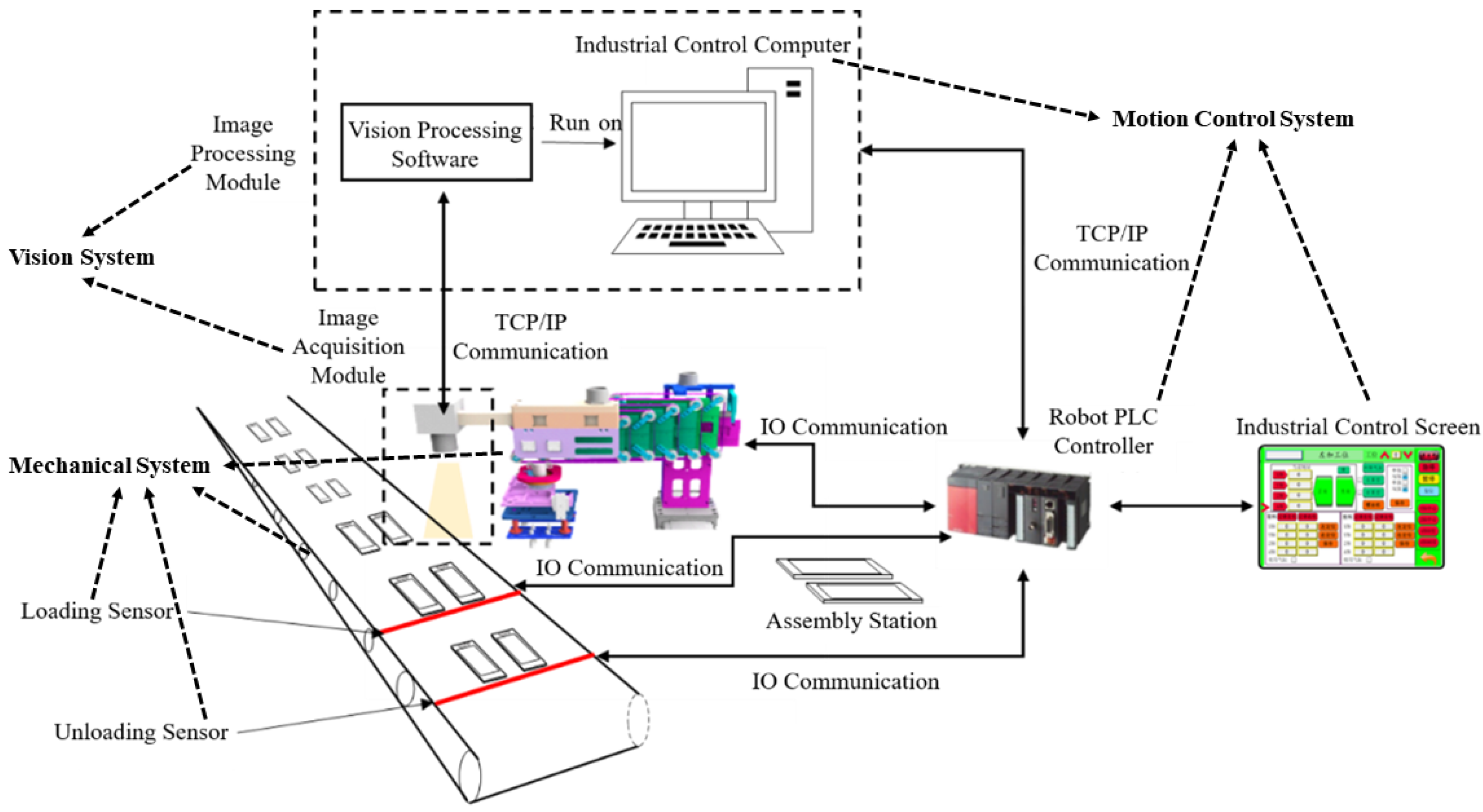
As shown in Figure 1, the system structure mainly consists of three parts: mechanical system, vision system, and motion control system.The mechanical system includes a four degrees-of-freedom right-angle robot, loading and unloading auxiliary equipment, sensors, etc.; the motion control system includes a vision industrial controller, robot programmable controller, and industrial control touch screen; the vision system mainly consists of an image acquisition module and an image processing module.
3.2. Mobile Phone Assembly Line Robot Hardware System
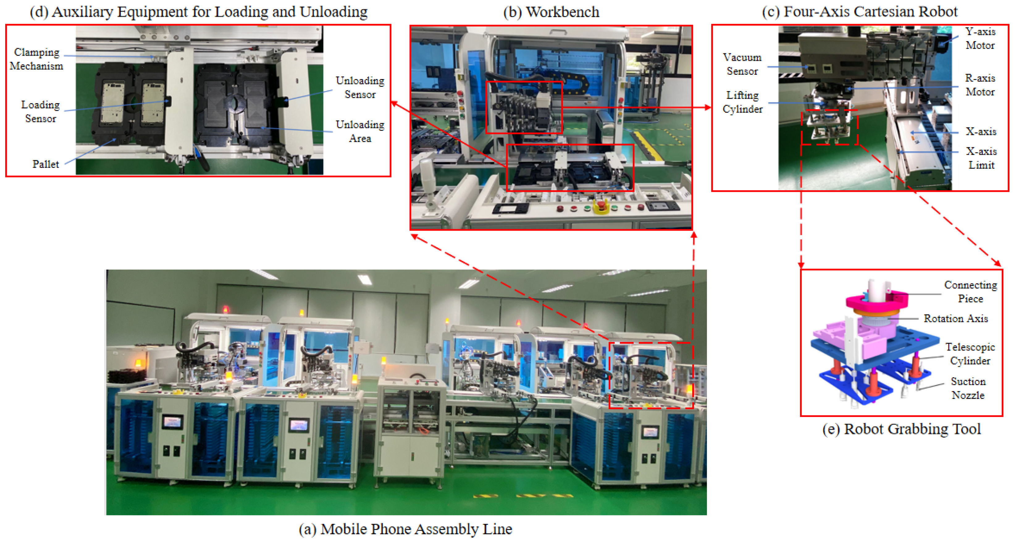
In this paper, a mobile phone assembly line as shown in Figure 2a is used as the research object. Because the mobile phone automatic assembly line has many processes, dense equipment arrangement, and limited space, the system selects a lightweight and retractable four degrees-of-freedom right-angle robot as shown in Figure 2c to achieve translational motion along the X, Y, and Z axes and rotational motion around the Z axis to meet the loading and unloading operation of the mobile phone frame. This right-angle robot has an X-axis travel range of 0 to 120 cm, a Y-axis travel range of −120 to 150 cm, a Z-axis travel range of 0 to 20 cm, and an R-axis rotation angle range of −180 to 180 degrees. Due to the lightweight and flat surface of the mobile phone frame, the end-effector of the four degrees-of-freedom robot is powered by two sets of suction cups and four circular nozzles of the same size installed in a square distribution as shown in Figure 2e.
The loading and unloading auxiliary equipment in the system, as shown in Figure 2d, mainly includes in-process pallets, loading and unloading sensors, and a pallet clamping mechanism. The in-process pallet is used as a carrier to load the semi-finished assembled product to flow into each assembly unit with the conveyor belt, which has a certain coarse positioning role to make the semi-finished products flow into each assembly unit in an orderly manner. The loading mechanism works synchronously with the pallet clamping mechanism. When the in-process pallet flows in, the sensor is triggered and the clamping mechanism clamps the pallet, making the pallet stationary relative to the conveyor belt; then the loading signal is sent to the robot through IO communication. After the robot picks up the material, the empty pallet flows into the discharging area, triggering the discharging sensor; the clamping mechanism clamps into the pallet and waits for discharging after the assembly operation.
3.3. Vision Hardware System
The hardware part of the vision system mainly includes industrial cameras, lenses, light sources, and industrial controllers with communication ports. As the offline vision function in the system needs to detect and analyze the hole characteristics of the phone frame, determine the best grasping position of the suction cup, and use it as a relative mark point in the online positioning system, the offline vision system needs to take a complete image of the phone frame. The online vision system function requires real-time identification to locate another marked point in the incoming frame and the rotation angle of the material, which can be achieved by taking only partial images. In summary, this system needs to design two sets of vision systems, in which online vision is installed at the end of the robot to move to a fixed position with the robot to take pictures and collect local images of the material in real-time, and offline vision collects the complete mobile phone frame image to be loaded in an external operation. The edge contour features of the mobile phone frame can be searched by grayscale values, so the online vision and offline vision systems both use monochrome CMOS cameras with fast acquisition speed and high integration. The specific hardware selection parameters are shown in Table 1, Table 2 and Table 3.
3.4. Grasping System Operation Flow
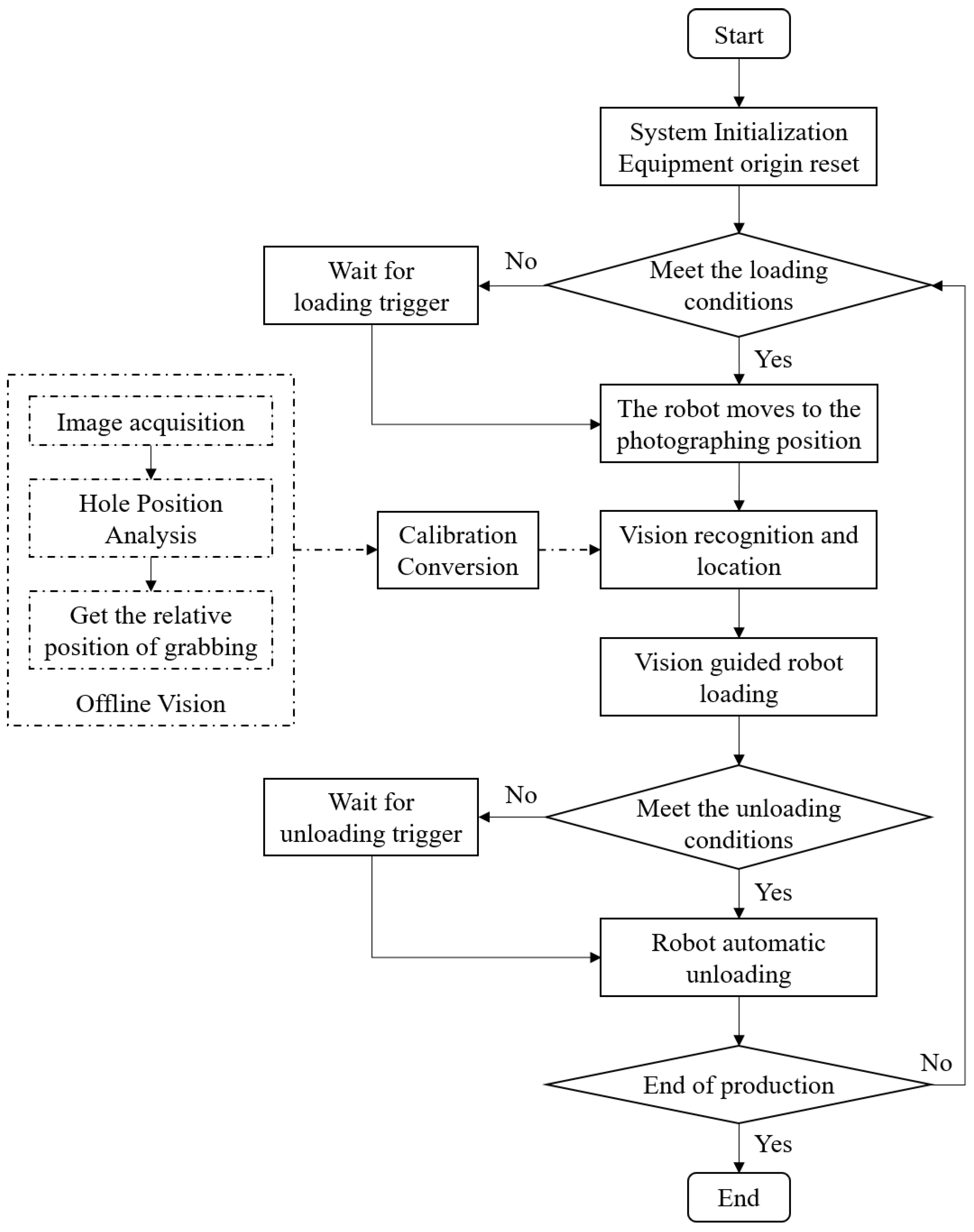
The operation flow of the whole grasping system is shown in Figure 3. The process includes starting the production line equipment, resetting each piece of equipment, and then entering the pending operation state. When the tray with the mobile phone frame flows into the loading station, the sensor is triggered and sends a high-level signal to the clamping mechanism, which then sends the loading and picking signal to the robot through IO communication after clamping the tray. The robot quickly moves to the photo position and controls the light source and then sends the acquisition signal to the vision system via TCP communication, which triggers the camera to acquire a frame of the image. The vision system identifies and locates the image, gets the actual grasping position of the phone frame in the image, and sends the position information command to the robot. The robot receives the control command and turns off the light source first, then adjusts the grasping position according to the position information to grab the material and place it on the assembly station to finish loading. After the assembly process is completed, the sensor will send an unloading signal to the robot to complete the unloading to the tray in the waiting area, then the clamping mechanism will be released and the phone frame will flow to the next assembly station with the tray.
4. Visual Guidance-Based Fast Grasping Technology Method for Differentiated Mobile Phone Frames
This section describes a robot grasping system for differentiated mobile phone frames and introduces a general scheme combining “offline vision analysis for grasping position” and “online vision positioning for grasping” to guide the robot to grab the differentiated mobile phone frames quickly.
4.1. Offline Image Information Extraction
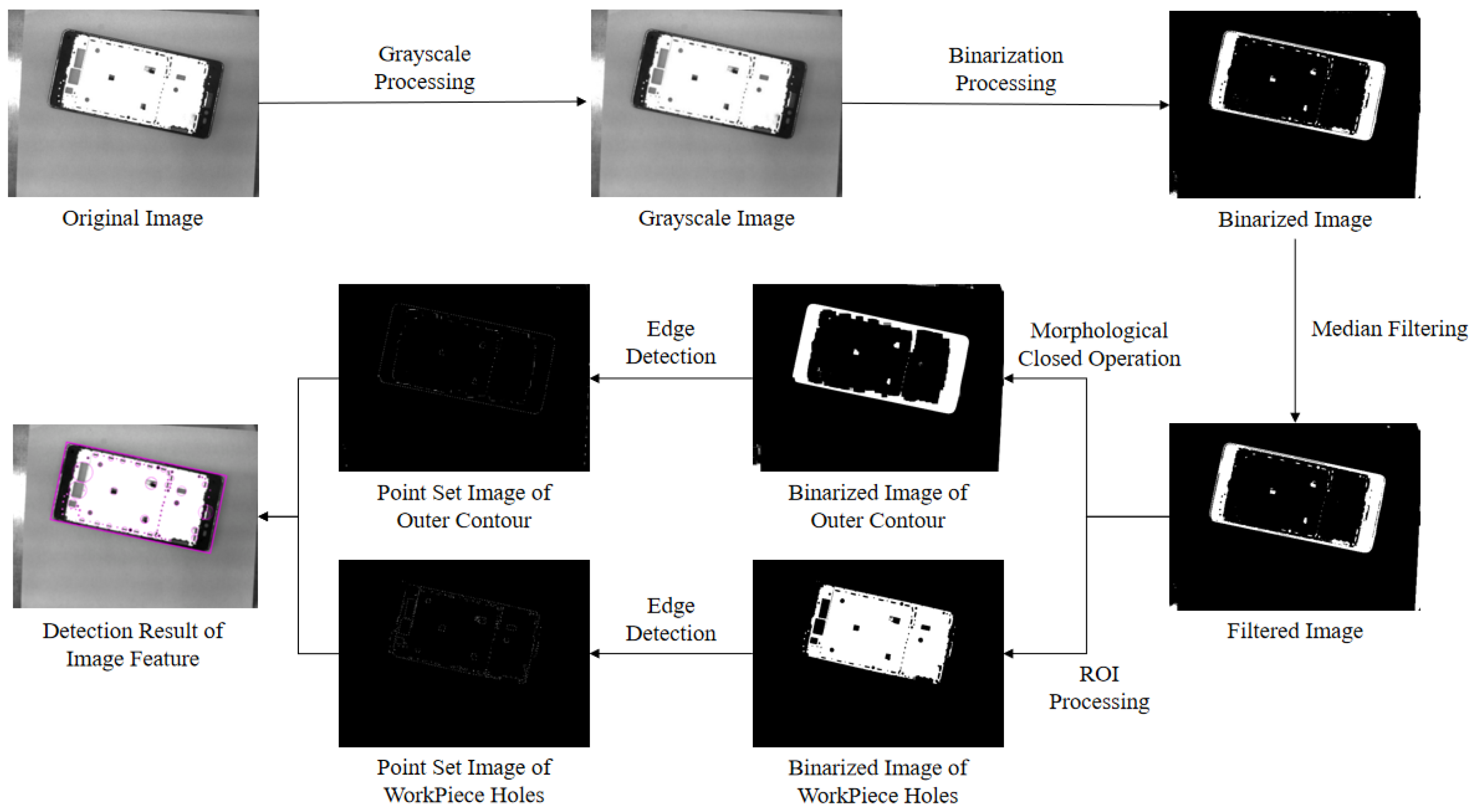
There are several holes of different shapes inside the middle frame of mobile phones, and the grasping point of the nozzle should avoid these holes as much as possible considering the robot’s stability when grasping the middle frame. The offline vision system acquires the complete mobile phone frame image at the external fixed bracket device and then pre-processes the image with image graying, binarization, filtering, morphological closed operation, and edge detection to enhance the edge feature information and eliminate the influence of useless features as much as possible while improving the computing efficiency of the subsequent algorithm processing [34]. The fitting algorithm of bounding rectangles with closed regions [35] is used to calculate the vector data information, such as the minimum external rectangle, perimeter, rotation angle, and center position of the outer edge contour of the mobile phone frame based on the images of the outer edge contour of mobile phone frame and the point set images of the inner hole edge contour extracted by the preprocessing of the offline vision system. For the convenience of subsequent calculation, the minimum covered circle algorithm for extracting the set of planar points [36] is used to extract the minimum external circle of the internal hole contour obtained after preprocessing to characterize the hole location and size information. The whole image pre-processing process and the final extracted results of the minimum external rectangle of the outer edge contour and the minimum external circle of the hole edge contour of the phone frame are shown in Figure 4, and the calculated image information data of the phone’s middle frame are shown in Table 4 and Table 5.
4.2. Robot Grasping and Positioning Algorithm
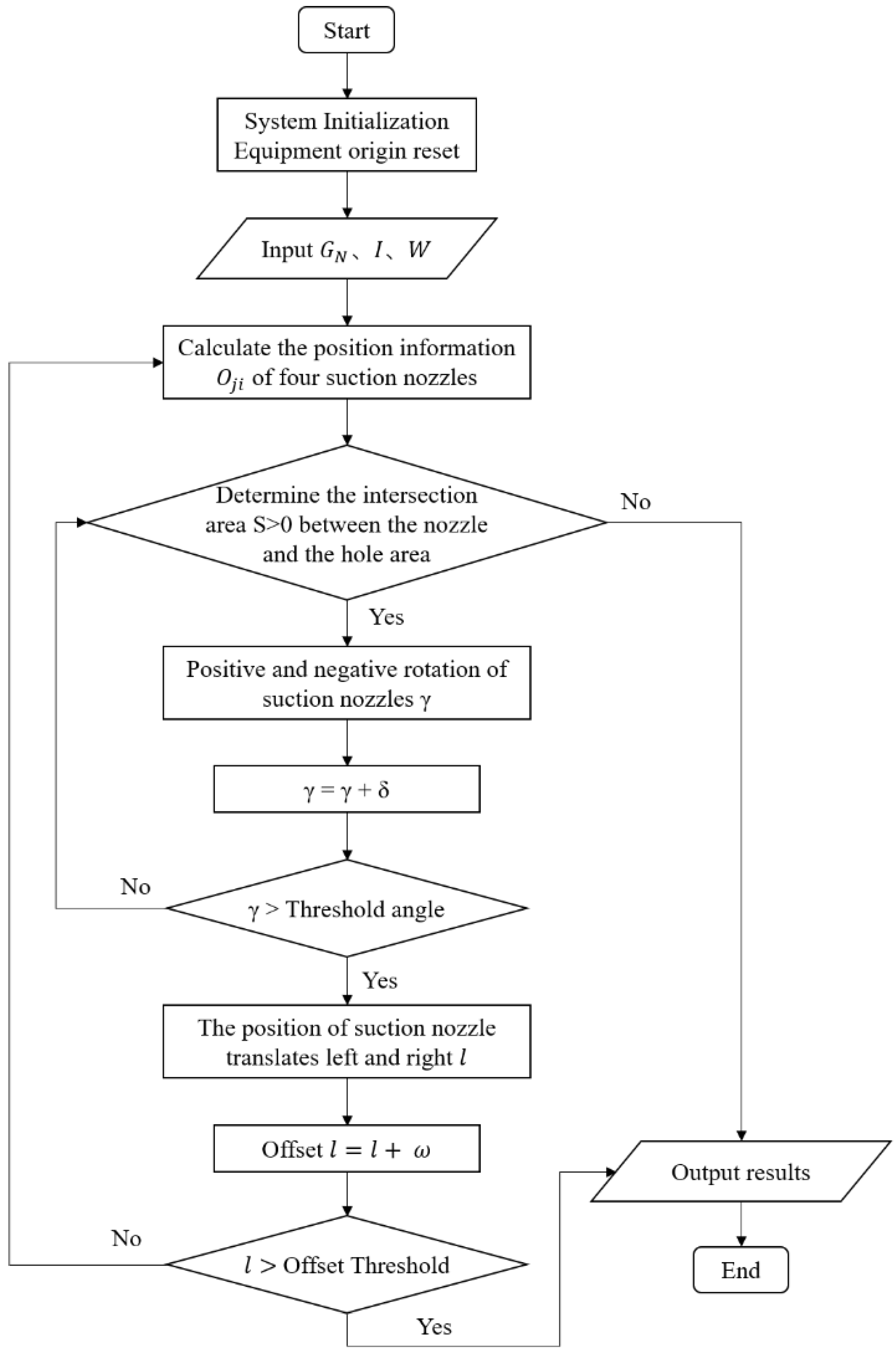
The positioning and grasping algorithm takes the vector information I of the phone frame in the image, the ensemble of hole features , the robot end-effector structure, and its suction nozzle size parameter W as inputs, calculates the intersection area S between the suction nozzle and the inner hole area of the middle frame, and searches for the suction cup position P and rotation angle that makes S equal to zero as the positioning position of the robot to grip the middle frame, which is the output of the algorithm. The specific flow of the algorithm is shown in Figure 5, where is the rotation angle increment and is the translation increment.
4.2.1. Grasping and Positioning Algorithm Design
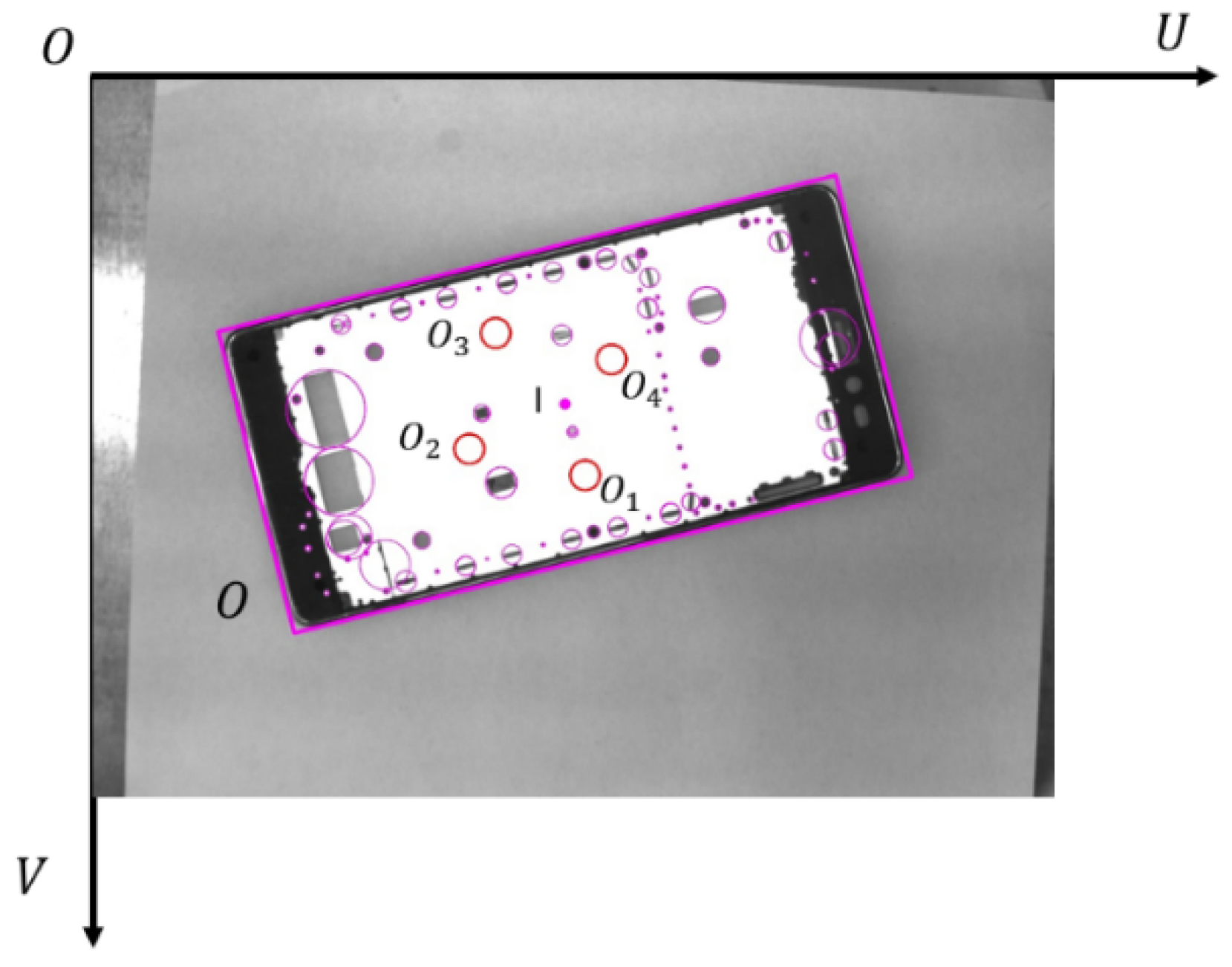
The length and width specifications of the middle frame extracted from the image features are set to a and b, the center coordinates of the workpiece under the image coordinate system are set to , and the N holes in the middle frame including feature location and contour size information are set to , where . Then the set of hole feature information can be expressed as . According to the end-effector of the loading and unloading robot described in Section 3, the distance between adjacent nozzles is set to l, the nozzle radius is set to r, and the set of nozzle information is set to , where O contains the pixel coordinate position information of each nozzle . Figure 6 illustrates the parameter distribution of the positioning model.
To complete the robot’s grasping and positioning, the off-line vision system needs to solve for the center positions of the four suction nozzles that do not overlap any hole positions as much as possible within the internal range of the workpiece at the time of grasping. The intersection area of the four nozzles and the hole is used as the measurement parameter to solve the center position of the four nozzles when the sum of the intersection area Sum is zero or minimum to determine the optimal grasping position of the robot, and a grasping and positioning solution model for the hole feature information of the middle frame is established as shown below.
In the above constraints, and denote the assumed coordinates of the corresponding nozzle i in the image coordinate system when the suction cup is at search position j, respectively, and k denotes the slope of the axis where the center point of the workpiece is located and , where is the workpiece vector angle. Constraint (2) indicates that is always on the workpiece axis, and Constraints (3) to (6) indicate that the center of the workpiece must be within the square of the four nozzles when the suction cups search for the grasping position on the workpiece, which is to guarantee the stability during grasping. The above constraints show that the closer the search grasping position is to the center of the workpiece, the better the grasping effect will be. Therefore, the model takes the center of the workpiece as the initial search point, and searches for the optimal rotation angle of the suction cup by rotating it clockwise and then counterclockwise in single increments until it is greater than the threshold angle, and then translates it in one incremental displacement l until it is greater than the translation threshold. In this way, combining the rotation and translation of the suction cups, the optimal grasping position and the corresponding suction cup rotation angle are searched on the workpiece by traversing the workpiece.
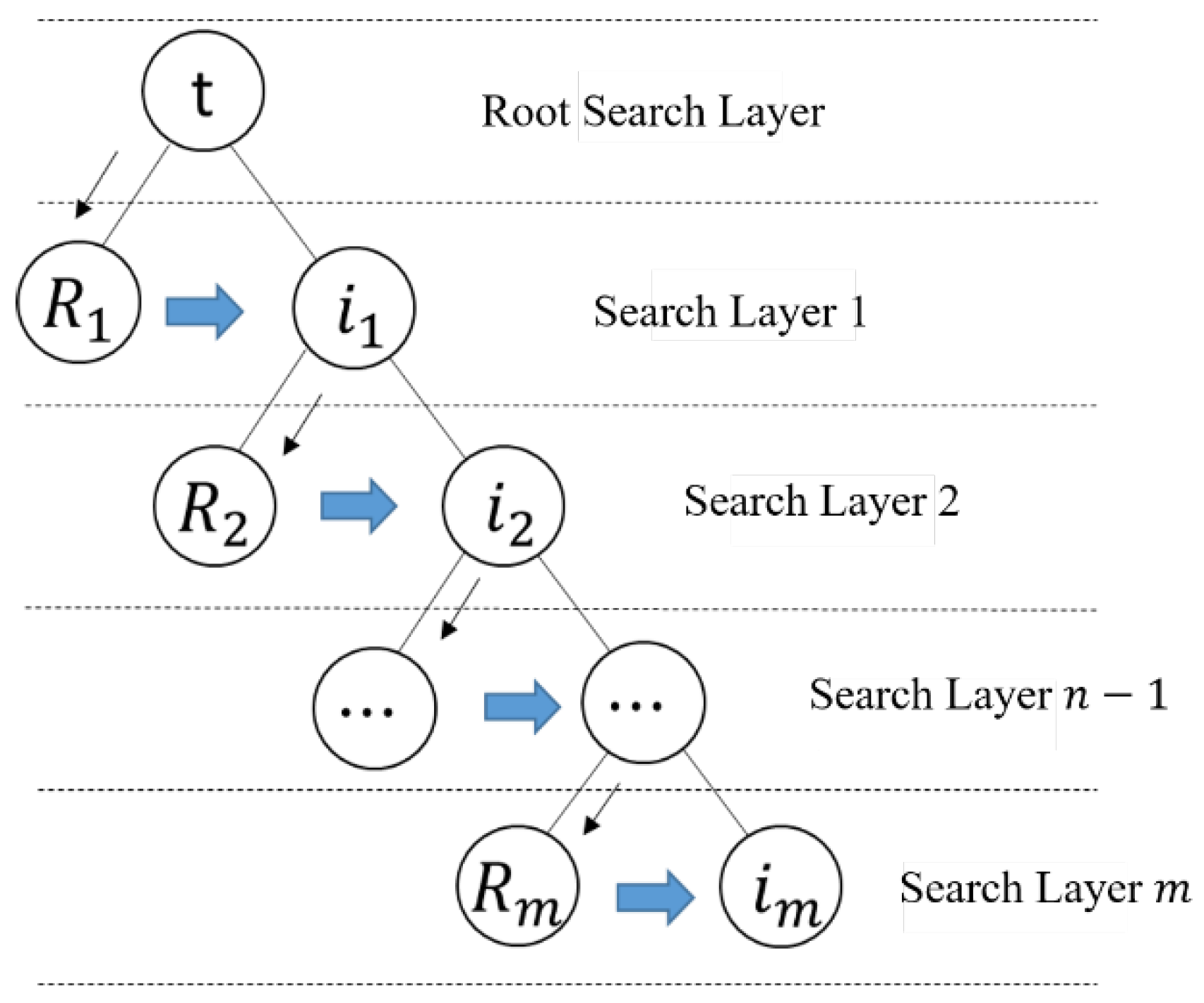
According to the constraint and solution requirements, a binary tree-like algorithm is used to calculate the intersection area of the four nozzles with the holes in the workpiece within the constraint range by traversing the top-down, left-to-right sequence hierarchically until the point that satisfies equal to zero is searched first, and then the search ends and the result is output. The hierarchical traversal structure of the algorithm is shown in Figure 7.
As shown in Figure 7, t indicates that the vector center of the middle frame is used as the root search node of the first search layer. In the next search layer, the search nodes of the process are divided into two categories, which are the set of rotating sucker search solution with the starting position of the search node in the previous layer and the set of moving the sucker position to the left and right of the search node in the previous layer. In this way, a full and non-complete binary tree with t as the root search node, as the left node and as the right node is established. The search path of this binary tree hierarchical traversal search strategy is , which belongs to the breadth-first search (BFS) strategy and can guarantee that the location searched is the closest point to the center of the workpiece, which meets the model constraints.
4.2.2. Algorithm Pre-Processing
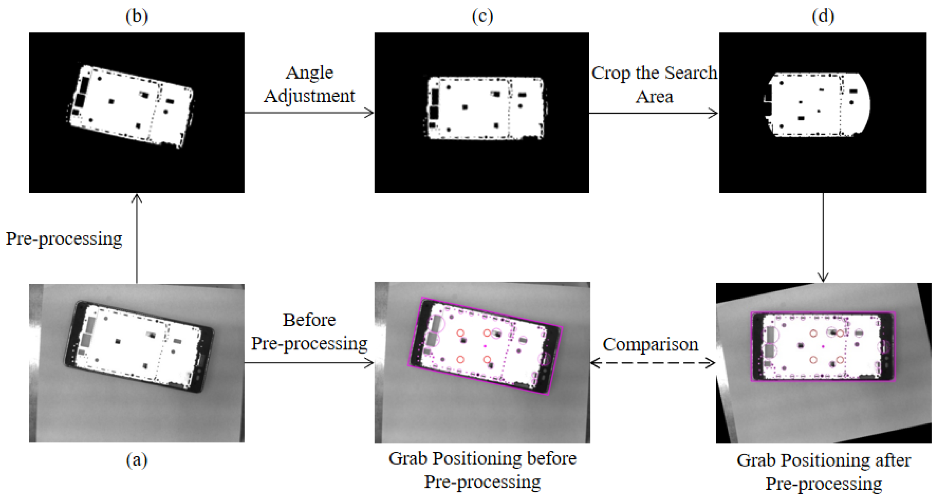
Because the placement of the phone frame is random in practice, the angle of the collected image poses is also different, which leads to an inconsistent angle of the suction cup relative to the workpiece when the algorithm searches for nodes at the root, and the results of the algorithm’s hierarchical traversal search have large differences. Therefore, before the algorithm is executed, it is necessary to adjust the corresponding negative angle according to the rotation angle of the phone frame image obtained during image preprocessing so that the phone frame in the image is always in a horizontal position, and thus the position angle of the suction cup relative to the workpiece during the initial search of the algorithm is always uniform. The image is angularly adjusted as shown in Figure 8c. After the angle adjustment, the limit position of the four nozzles in the search process within the constraint range of left and right translation at the initial position is , and the limit distance that can be searched by the nozzles up and down during the rotation search is . The search domain can be cropped to reduce the set of hole features in the search domain, thus reducing the search time of the localization algorithm. The trimmed search domain is shown in Figure 8d.
4.2.3. Algorithm Results
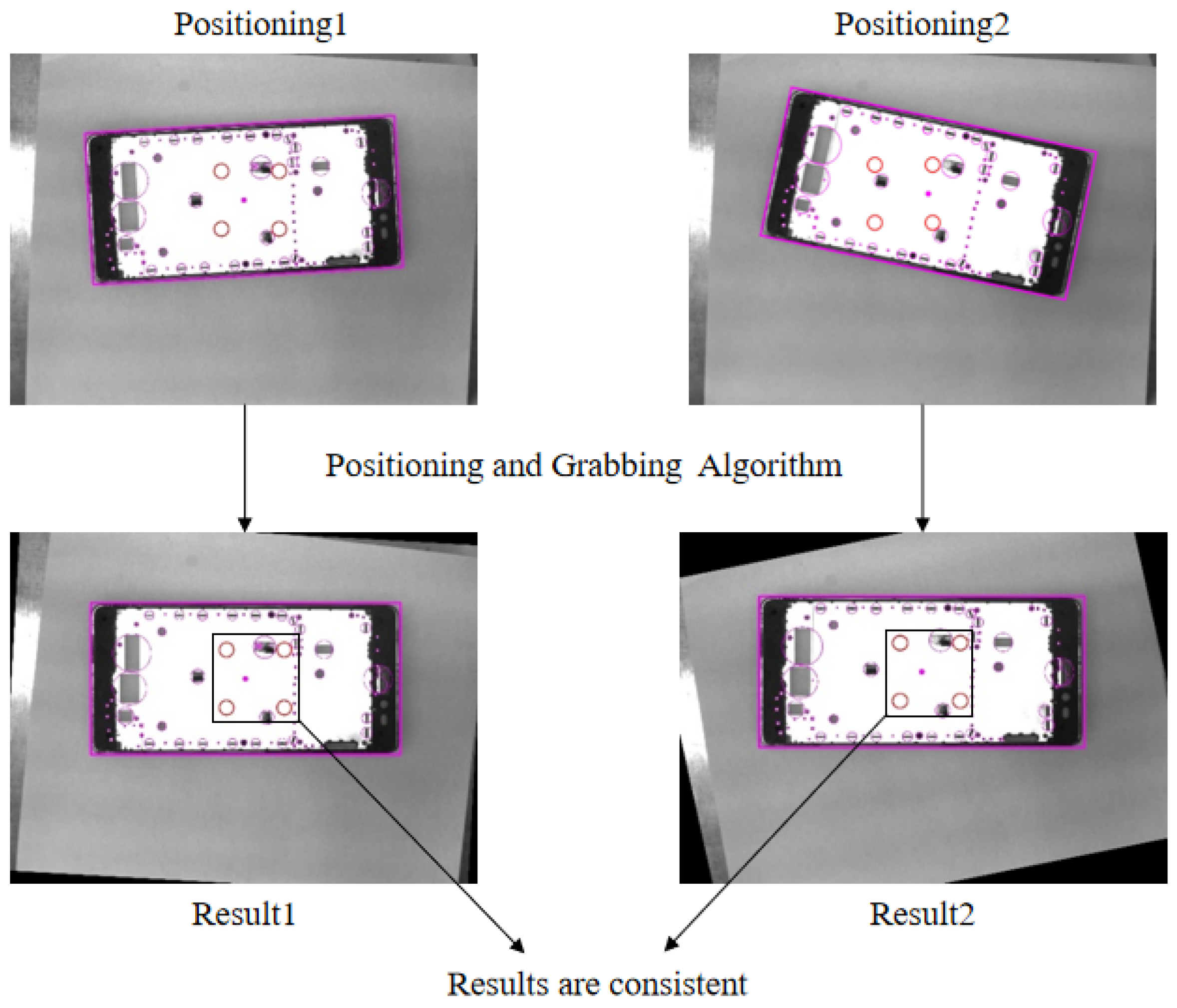
The positioning results of the grasping and positioning algorithm for the same mobile phone frame at different placement positions and angles are shown in Figure 9, and the final positioning results are consistent despite the inconsistent positions and angles of the captured images.
4.3. Online Image Target Recognition
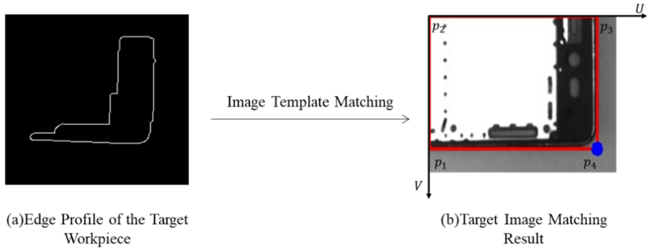
The offline vision system completes the robot’s positioning of the mobile phone mid-frame grasping position and provides the image template of the phone frame. The online vision system traverses the set of edge contour features obtained from the online acquisition detection, finds the largest edge contour of the workpiece edge containing the most contour points as shown in Figure 10a, sets it as the template contour to be matched, and performs template matching with the image template provided by the offline system [37,38] to identify and obtain the positional information of the target middle phone frame in the matched image. Because only the rotation and translation information of the phone frame in the two-dimensional plane needs to be considered, and the frame in the image is clearly distinguished from the surrounding background pixels with prominent edge contour information, an edge-based matching algorithm is used to match and identify the local images captured by online vision. The similarity between the template edge contour and the edge contour to be searched is evaluated using the Hausdorff [39] distance method.
After matching the middle target frame outline, it is also necessary to determine the outline direction of the frame and mark the edge points of the target outline as a Mark point for visual localization. The target contour’s minimum outer rectangle and its edge points’ coordinates obtained by off-line vision are shown in Figure 10b. Using p4 in the figure as the positioning Mark point and the slope angle of the line connecting and to calculate the position angle of the target workpiece, the calculation formula is shown as follows:
4.4. Camera Calibration
Camera calibration of the online and offline vision systems is required after target image matching [40]. The offline vision camera takes pictures at a fixed location point directly above the plane perpendicular to the phone’s middle frame. Ignoring the effect of lens distortion, the pixel calibration of offline vision represents the coordinates of the four edge points of the smallest outer rectangle in the captured workpiece image as the four edge point coordinates positions of the phone’s middle frame, respectively. Then the length a of the rectangular phone frame pixel can be expressed as , the width b can be expressed as , and the pixel perimeter is expressed as C. Whereas the actual phone mid-frame perimeter is C, the calibrated offline visual unit pixel corresponds to the actual physical size as in Equation (8).
The camera of in-line vision is mounted at the robot’s end and moves a fixed distance along the X-axis and Y-axis with the robot to take pictures, so the active vision self-calibration method [41] is used for calibration. We select the center of the phone frame as the calibration target point, control the robot to move a fixed distance along the X-axis and Y-axis, respectively, and record the pixel coordinates of the calibration target point at this time; the distance value between the two acquisition points on the X-axis line where the camera is located and the distance value between the two acquisition points on the Y-axis line can be calculated. Then the physical sizes and of the online vision unit pixel in the robot coordinate system can be found from the pixel distance and corresponding to the X-axis and Y-axis between these two acquisition points in the image coordinate system, as shown below in Equations (9) and (10), respectively.
Because the mobile phone mid-frame material is located at the same height in the robot loading and unloading system, there is no need to detect the height information of the mid-frame to be measured. The online vision system moves with the robot to the photo point to collect the image and obtain the coordinates of the calibration target in the robot base coordinate system, control the laser pointer in the center of the suction cup to align the target, and read the physical coordinates of the target from the robot controller. Nine datasets are collected randomly, and the calibration transformation matrix is solved to complete the calibration. The two-dimensional set of mapping equations between the image coordinate system and the robot coordinate system is established based on the camera imaging model and is shown in Equation (11) below. The optimal parametric solution of this set of equations can be calculated by collecting nine sets of data and then fitting the equations using the least squares method [42].
4.5. Vision-Guided Robot Positioning and Grasping
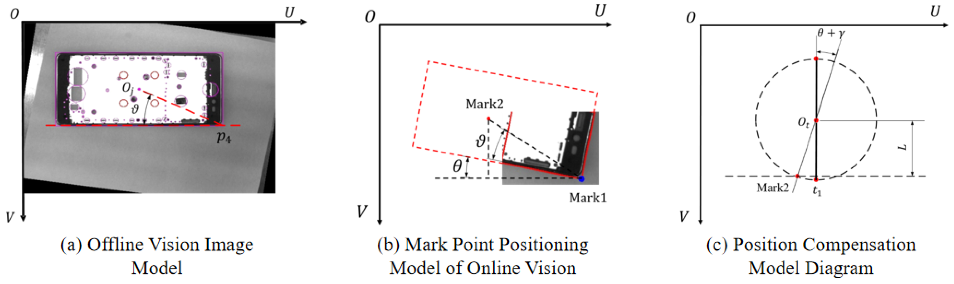
After completing a series of preparations, such as target identification and camera calibration for online image acquisition, the online vision system will guide the robot to move to the best position for mobile phone frame grasping calculated by the offline vision system and grab the material. Therefore, the grasping position of the robot’s end-effector needs to be calculated and the movement path needs to be planned. The coordinates of the lower right corner point of the local image are marked as Mark1 in the above online image target recognition process, and the relative position point is obtained as another marked point in the global range of the workpiece according to the offline grasping and positioning model and recorded as Mark0. The online vision calculates the grasping position of the robot end-effector from the relative position relationship between these two mark points and the workpiece position angle. However, as the two mark points do not belong to the same vision system, it is necessary to convert Mark0 to Mark2, a localization point in the online vision image coordinate system.
The offline vision localization model is shown in Figure 11a, where Mark0 is the grasping point , and the pixel coordinates of the lower right point of the frame in offline vision are . The actual distance between and represents the grasping relative distance , and the calculation formula is shown in Equation (12). In the positioning model, the angle ( greater than zero) denotes the angle between the line connecting and and the U-axis of the image coordinate system. The formula for calculating is shown in Equation (13).
The online visual mark point localization model is shown in Figure 11b. The online vision system locates the lower right corner point of the workpiece as Mark1 in real time, and its pixel coordinates are marked as (u, v); is the rotation angle of the phone frame. Based on the grasping relative distance determined by offline vision, the pixel coordinates of another localization point in the online vision image coordinate system can be figured out according to Equations (14) and (15), and noted as Mark2 (u, v). When is greater than zero, the workpiece rotates clockwise; when is less than zero, it means that the workpiece rotates counterclockwise.
Because the suction cups of the robot end-effector and the rotation axis of the robot center are different, the suction cups will cause position deviation when they rotate. Therefore, in actual operation, the suction cup grasping point must be converted into the position corresponding to the TCP tool to achieve position compensation to obtain the effective position of robot motion. Combining with the actual application scenario of this study, a direct calculation method is designed for position compensation based on the known distance from the center of the suction cup to the TCP of L mm. The calculation model is shown in Figure 11c. Knowing that the Mark2 pixel coordinates are (u, v) and the suction cup center position is , the robot TCP position is calculated as shown in Equations (16) and (17) below.
When the robot end-effector rotates clockwise, is greater than zero, the calculation symbol of Equation (17) is “+”, and the calculation symbol of Equation (18) is “−”. In contrast, when the robot end-effector rotates counterclockwise, is less than zero, the calculation symbol of Equation (17) becomes “−”, and the calculation symbol of Equation (18) becomes “+”. The actual robot end-effector motion positions () can be obtained by substituting () calculated when the grasping position angle is into Equation (11), and then converting them into robot control commands to realize the vision-guided loading function.
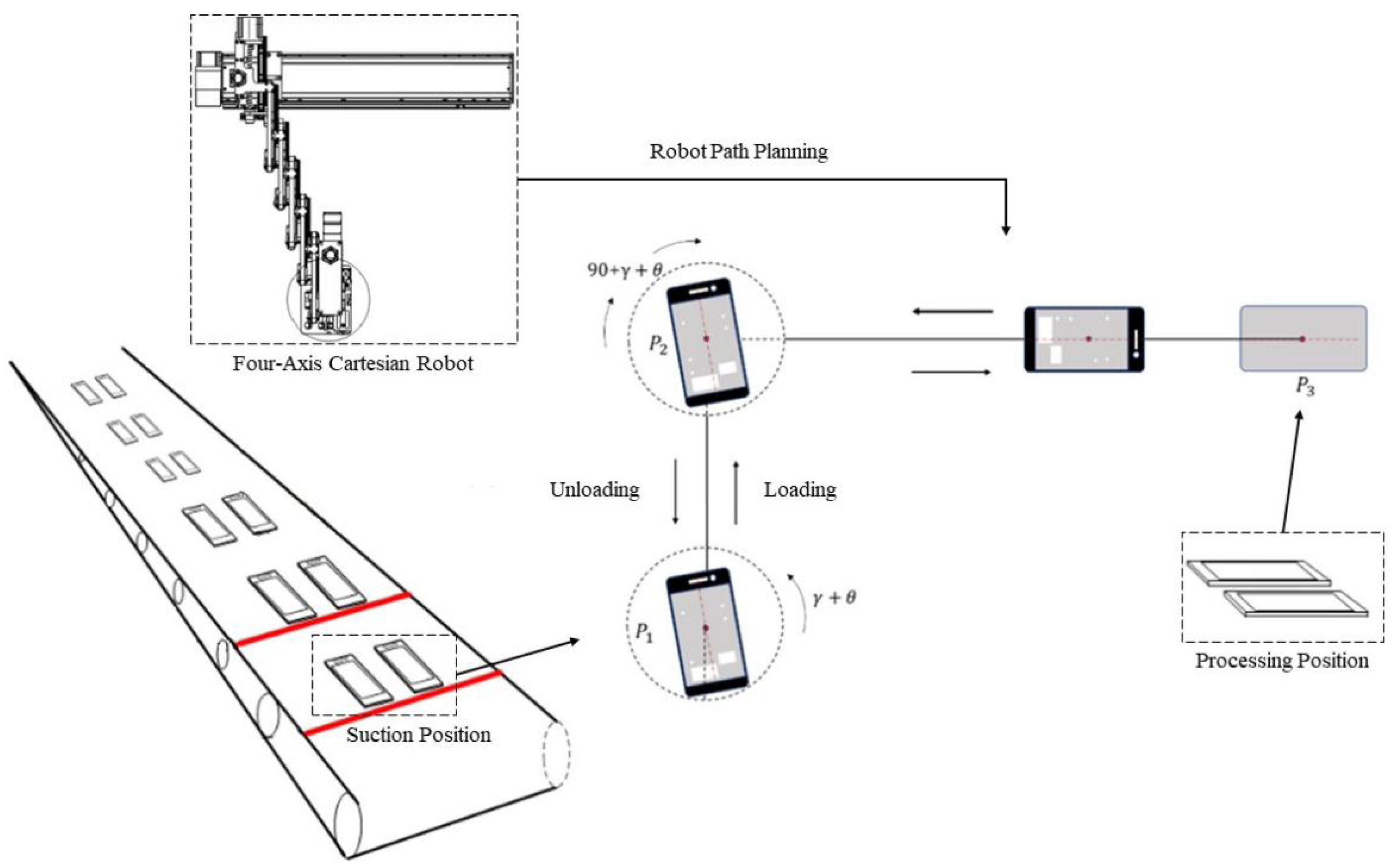
When the robot is loading the material and executing the “grasping–placing” action, we consider the rotation angle of the workpiece itself and the relative angle of the suction cup grasping and design to adjust the suction cup angle after every two loading actions according to the grasping position and placement position of the material, which effectively reduces the time of stopping to adjust the suction cup angle and improves the smoothness of movement and loading speed. From previous research work, it can be calculated that the visual guide grasping coordinates are (), the angle of the workpiece itself is , and the rotation angle of the suction cup grasping is . Therefore, we carry out the path planning for the robot end-effector, as shown in Figure 12.
In Figure 12, is the suction position, is the material angle adjustment position, and is the teaching placement point. The robot adjusts the material axis at point to coincide with the axis of the placement point, and the final path planning is shown in Equation (18). Specific to the robot’s action is the robot end-effector movement to the suction position point and the suction cup rotation angle (); then the robot decentralizes and waits for the suction cup to lift the middle frame after absorbing it, then moves to the point and adjusts to angle (), and finally moves to the placement point , places the workpiece, and completes the loading and unloading of the middle frame of the mobile phone.
5. Experimental Platform Construction and Analysis of Experimental Results
5.1. Experimental Platform and Environment
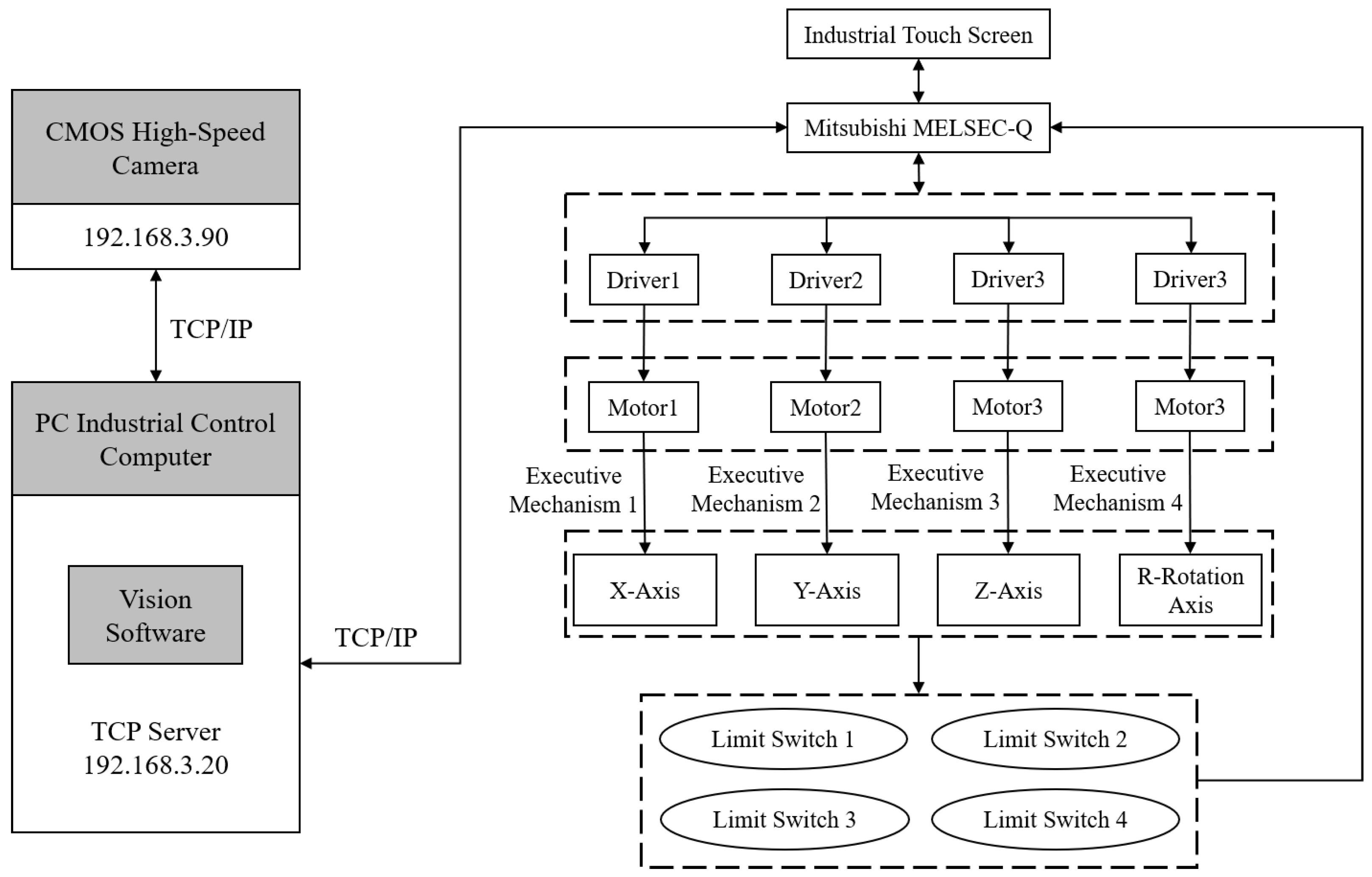
The experiment combines the hardware selection in Section 3 and builds the experimental platform for visually guided grasping of mobile phone mid-frame based on the system control framework as shown in Figure 13. The online vision CMOS high-speed camera acquires the image, transmits it to the vision system software running on the IPC for image pre-processing and template matching recognition, obtains the image position coordinates of the frame, and calculates the actual grasping position of the robot after calibration conversion and position compensation. Finally, the robot motion posture information is sent to the robot programmable controller via TCP communication to realize the vision-guided 4-axis right-angle robot for accurate grasping.
This experiment developed the vision system software based on the Windows 10 operating system to control the operation of each step of the grasping experiment, image visualization, and acquisition of experimental data. The software uses Visual Studio 2017 as the development platform, and the development environment is .NET Framework 4.0. Using the UI interface class library provided by the Winform module under the platform specifically for desktop application development, the operation interface of the software is custom designed. The vision system running environment is Windows 10-64 bit. The hardware parameters of the IPC used in this experiment are as follows: VBOOK-121, Intel core i5, 4G RAM. The image-processing dependency libraries used in the vision system development process are HALCON, OpenCV, etc. This experiment is partly based on Python-OpenCV for image processing and grasping algorithm implementation. Based on the above development environment, development platform, and algorithm library, we used joint C# programming language to complete the design and development of the vision system.
5.2. Experimental Technical Specifications
Table 6 gives the technical specifications of the vision-guided robot grasping in this experiment.
5.3. Experimental Results and Analysis
5.3.1. Experiment on the Stability of the Grasping and Positioning Algorithm
Stability experiments were conducted on the mobile phone mid-frame grasping and positioning algorithm to verify whether the algorithm is applicable to the mobile phone mid-frame with differentiated hole feature distribution.
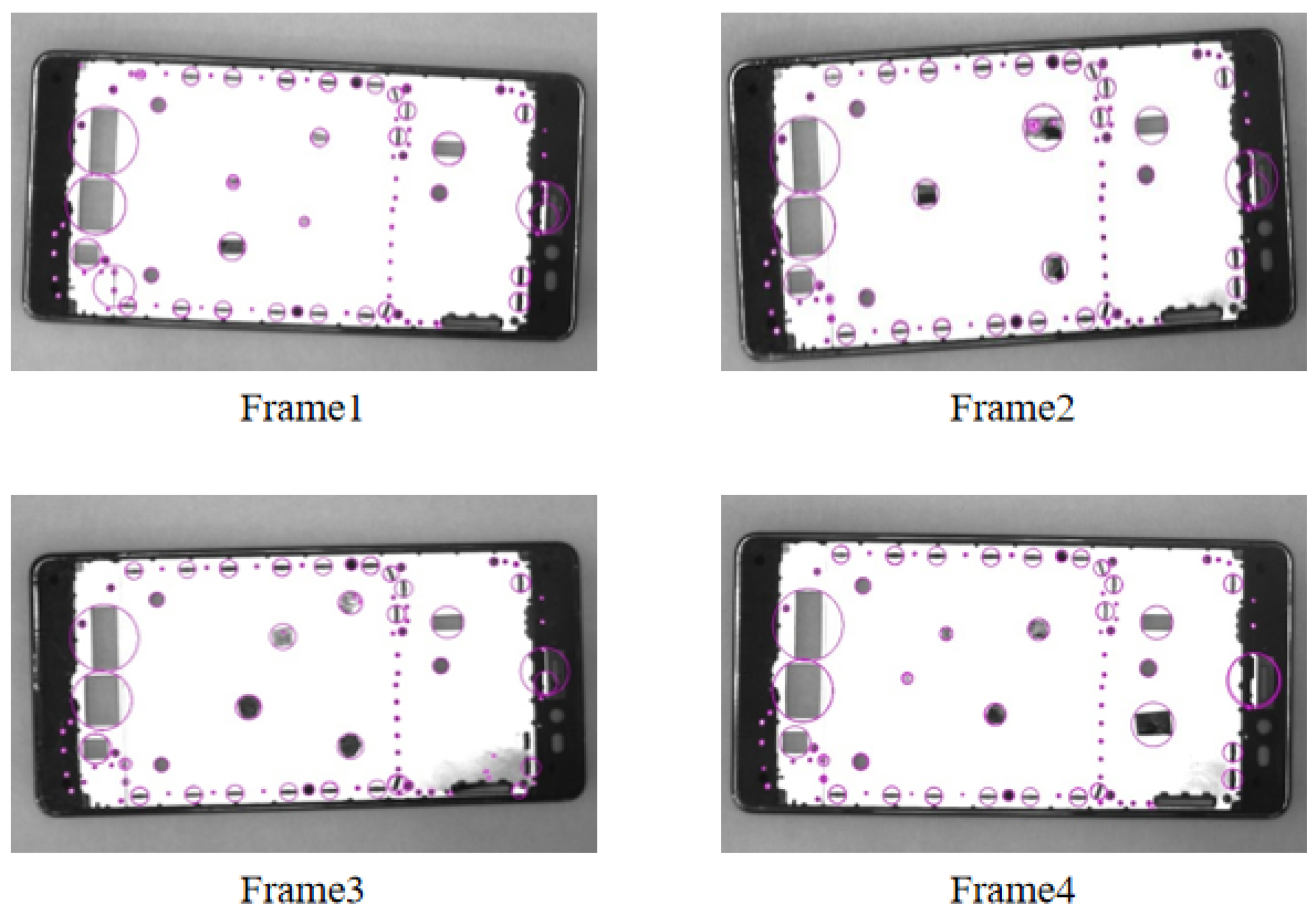
The experiments were conducted to detect and analyze four types of mobile phone mid-frames with differential hole distribution, as shown in Figure 14. In the experiment, four sets of data were detected for each type of the mid-frame, and the relative pixel distance values were calculated from the grasping point to the lower right corner point () for each positioning. The calculated experimental data are shown in Table 7.
From the analysis of the above experimental data, it can be seen that the grasping localization algorithm has a localization error within 1.5-pixel units for the four types of mid-frames with differentiated hole characteristics, indicating that the algorithm is stable and applicable to the recognition and localization of different models of mid-frames.
5.3.2. Pixel Calibration Experiment
According to the workpiece image information acquisition method described in Section 4.1, the offline system collects ten mobile phone mid-frame images for pixel calibration experiments. The experimental data of the pixel perimeter and the actual perimeter of the rectangular middle frame are shown in Table 8. We take the average of ten sets of data calibration results in Table 8 as the pixel calibration results of the offline vision camera and get the calibration results with equal to 0.08436 mm per pixel.
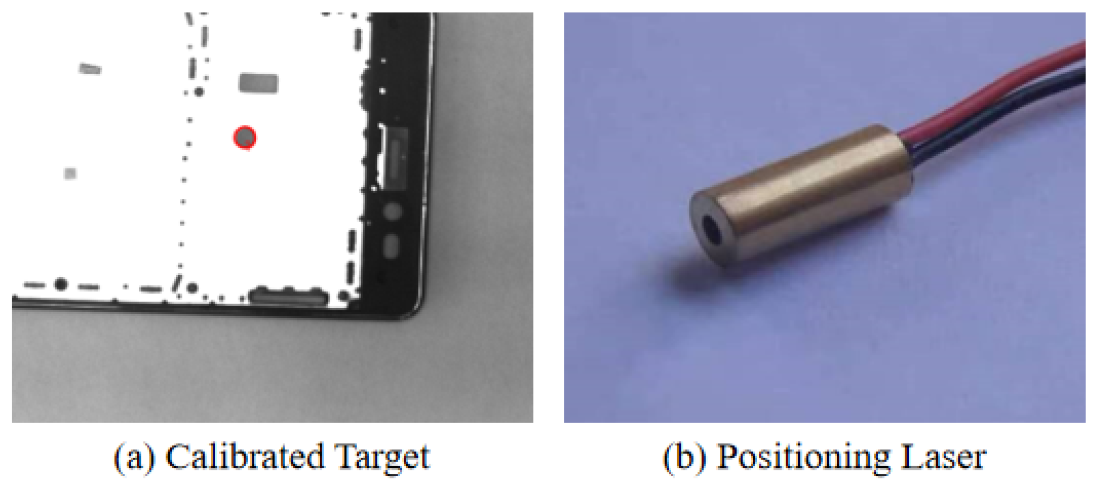
For the calibration of online vision, the nine-point calibration method is used to solve the transformation matrix M between the image coordinate system to the robot coordinate system by the least squares method. The calibration process is as follows: select the center of a circular hole feature in the middle frame as the calibration target, as shown in Figure 15a, then control the robot to move until the target enters the visual field of view and collect a calibration image and obtain the pixel coordinates of the target. After the image is acquired, the robot is controlled to move so that the positioning laser installed in the center of the nozzle of the end-effector as shown in Figure 15b is aligned with the position of the target point, and we record the physical coordinates of the target point in the robot coordinate system. We ensure that the target point is always within the visual field of view and randomly collect nine sets of data to complete the calibration as described in Section 4.4. The calibration experimental data obtained according to the above calibration process are shown in Table 9.
Using the data in Table 9, the pixel calibration results of online vision can be figured out: is equal to 0.245 mm per pixel and is equal to 0.245 mm per pixel, thus calculating the robot loading calibration conversion matrix M as shown below:
Supposing that the lower right corner point of the mobile phone frame is Mark1 (u, v) in the image pixel coordinate system, Mark2 (u, v) of the mid-frame at this time can be calculated according to the calculation method described in Section 4.5. After position compensation calculation to obtain the TCP position of the robot end-effector, its two-dimensional coordinates in the robot coordinate system can be calculated according to Equation (20). Subsequently, after the demonstration sets the uniform grasping height, the visually guided grasping can be realized.
5.3.3. Vision-Guided Robot Grasping Experiment
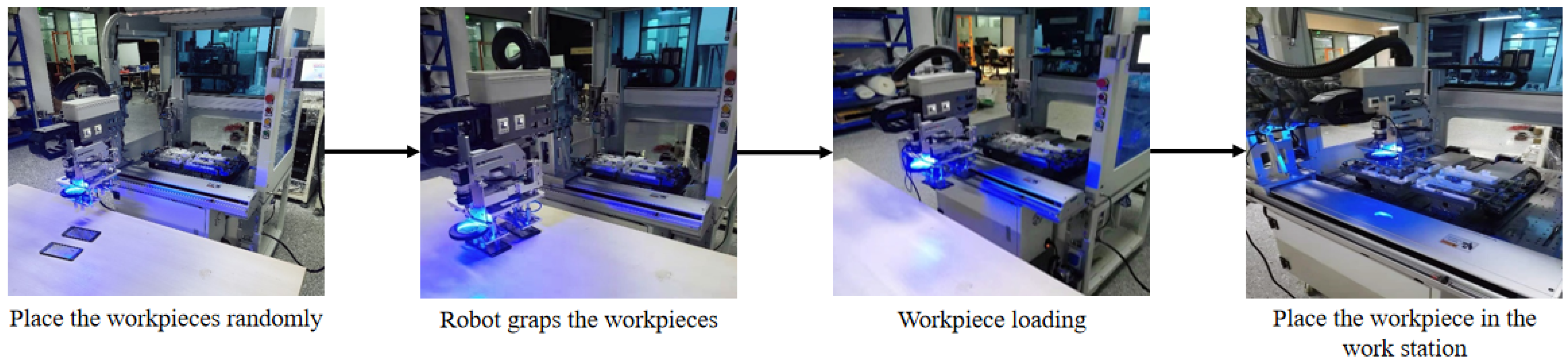
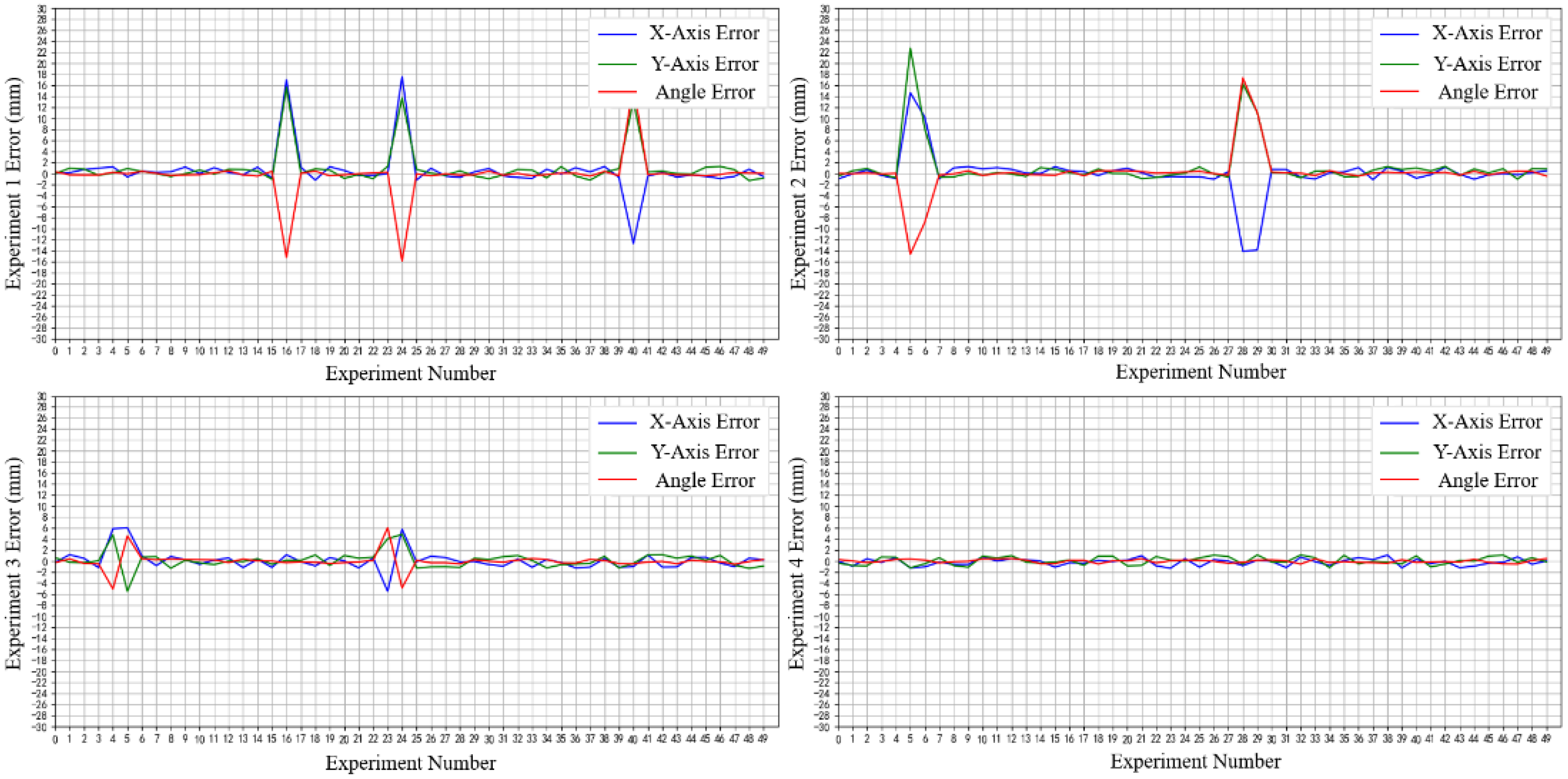
The experiment first adjusted the focal length and aperture flux of the camera installed at the robot’s end and set the fixed photo position and discharge position by demonstration. According to the experimental setup, the vision system is calibrated first, followed by the vision-guided robot positioning and grasping experiment. In order to collect clear local features of the target workpiece, the material position should always be ensured to be within the field of view of the fixed photo point. The vision-guided grasping experimental platform and process are shown in Figure 16. Fifty gripping experiments were performed in sequence, the positioning error after the workpiece reached the target position was recorded, and the results of the experimental error analysis are shown in Figure 17.
As the analysis of the experimental data in Figure 17 shows, the overall error of the four groups of experimental data fluctuates between −2 mm and 2 mm, except for the abnormal error fluctuations in the error values in group (1), group (2), and group (3). According to the analysis of field practical experience, the reason for this abnormal fluctuation is that the random offset angle of the workpiece during the experiment is too large [29], which is beyond the adjustment range of the suction cup. After eliminating the abnormal data, the statistical analysis of the experimental error was carried out, and the statistical results are shown in Table 10.
The experimental errors in Table 10 are actually the cumulative errors of the whole system, including the positioning errors caused by both the robot and the algorithm, where the repeatability of the robot is ±0.1 mm. In the four groups of fifty experiments, the success rate is more than 95%, the maximum error in X-axis is 1.25 mm, the maximum error in Y-axis is −1.29 mm, and the maximum error in angle is 0.5. In the four groups of experiments, the robot grasping experimental error is within 1.5 mm, which meets the loading and grasping accuracy requirement. During the experiment, when switching between experiments, it is only necessary to re-enter the relative grasping position parameters of the corresponding frame into the vision system, replace or re-create the matching template, and then the new material can be visually guided to grab. The experimental switchover process takes less time to adjust, the adjustment method is simple and fast, and the experimental results verify the effectiveness and rapid response of the flexible grasping scheme of “offline vision analysis grasping position” and “online vision positioning and grasping”, which meets the fast and highly adaptable production requirements.
6. Conclusions
This paper proposes a vision-guided robot positioning and grasping method by combining “offline vision analysis of grasping position” and “online vision positioning and grasping” for a mobile phone assembly scenario in which the loading robot’s end-effector must avoid the hole in the middle frame of the phone. The proposed robot end-effector grasping and positioning algorithm to avoid the hole in the middle frame can significantly ensure the grasping position is close to the center of the workpiece and calculate the relative position of the grasping based on the full and non-complete binary tree hierarchical traversal search strategy by analyzing the extracted information of the hole in the frame through offline visual inspection. Online vision based on the Hausdorff distance edge matching algorithm was used to obtain mobile phone mid-frame positional information through the camera calibration and hand–eye calibration to complete the coordinate position unification, and we designed a robot end-effector motion position compensation calculation method to achieve the robot end-effector motion path planning, and, finally, we completed the research work on the differential mobile phone middle frame visual guidance grasping.
Of course, this study is still relatively limited in what it investigates in terms of vision-guided loading robot positioning and grasping technology, as it is only for the vision-guided grasping method of mobile phone mid-frame in a two-dimensional plane. Although the experimental results in this paper verify that the method meets the accuracy requirements of the application scenario of this project, further improvements are still needed. For example, because online vision can only capture local images at present, the workpiece hole analysis and its grasping and positioning algorithm cannot be integrated into the online vision system, which reduces the system integration. It is necessary to optimize the online vision image acquisition function further and integrate the offline vision function into the online application software.
Author Contributions
Conceptualization, R.Z. and W.X.; Methodology, R.Z. and Z.B.; Software, Z.B. and S.Z.; Validation, R.Z. and G.Z.; Formal analysis, Y.X.; Investigation, G.Z.; Resources, J.L.; Data curation, Z.B. and S.Z.; Project administration, J.L.; Supervision, R.Z. and J.L.; Visualization, Z.B.; Writing (original draft), R.Z. and W.X.; Writing (review and editing), Z.B. and S.Z.; Funding acquisition, J.L. All authors have read and agreed to the published version of the manuscript.
Funding
This work was supported by the National Natural Science Foundation of China under Grant No. U20A6004 and 52075107; and the Natural Science Fund of Guangdong Province under Grant No. 2022B1515020006.
Conflicts of Interest
The authors declare no conflict of interest.
References
- Marwan, Q.M.; Chua, S.C.; Kwek, L.C. Comprehensive review on reaching and grasping of objects in robotics. Robotica 2021, 39, 1849–1882. [Google Scholar] [CrossRef]
- Hentout, A.; Aouache, M.; Maoudj, A.; Akli, I. Human–robot interaction in industrial collaborative robotics: A literature review of the decade 2008–2017. Adv. Robot. 2019, 33, 764–799. [Google Scholar] [CrossRef]
- Das, S.K. Smartphone Hardware and System Design. In Mobile Terminal Receiver Design: LTE and LTE-Advanced; Wiley Telecom: Hoboken, NJ, USA, 2017. [Google Scholar]
- Zhao, R.; Zou, G.; Su, Q.; Zou, S.; Deng, W.; Yu, A.; Zhang, H. Digital twins-based production line design and simulation optimization of large-scale mobile phone assembly workshop. Machines 2022, 10, 367. [Google Scholar] [CrossRef]
- Gobee, S.; Durairajah, V.; Xin, K.; Jie, L.L. Robotic vision based PCB inspection with IOT interface. In Proceedings of the 2018 3rd International Conference on Control, Robotics and Cybernetics (CRC), Penang, Malaysia, 26–28 September 2018; pp. 27–31. [Google Scholar]
- Zhou, Y.; Fang, Q.; Zhao, K.; Tang, D.; Zhou, H.; Li, G.; Xiang, X.; Hu, T. Robust task-oriented markerless extrinsic calibration for robotic pick-and-place scenarios. IEEE Access 2019, 7, 127932–127942. [Google Scholar] [CrossRef]
- Enebuse, I.; Foo, M.; Ibrahim, B.S.K.K.; Ahmed, H.; Supmak, F.; Eyobu, O.S. A comparative review of hand-eye calibration techniques for vision guided robots. IEEE Access 2021, 9, 113143–113155. [Google Scholar] [CrossRef]
- Sam, R.; Nefti, S. A novel, flexible and multi-functional handling device based on Bernoulli principle. In Proceedings of the 2011 IEEE International Conference on System Engineering and Technology, Shah Alam, Malaysia, 27–28 June 2011; pp. 166–171. [Google Scholar]
- Liu, D.; Wang, M.; Fang, N.; Cong, M.; Du, Y. Design and tests of a non-contact Bernoulli gripper for rough-surfaced and fragile objects gripping. Assem. Autom. 2020, 40, 735–743. [Google Scholar] [CrossRef]
- Li, X.; Kagawa, T. Development of a new noncontact gripper using swirl vanes. Robot. Comput.-Integr. Manuf. 2013, 29, 63–70. [Google Scholar] [CrossRef]
- Maggi, M.; Mantriota, G.; Reina, G. Introducing POLYPUS: A novel adaptive vacuum gripper. Mech. Mach. Theory 2022, 167, 104483. [Google Scholar] [CrossRef]
- Xu, W.; Zhang, H.; Yuan, H.; Liang, B. A compliant adaptive gripper and its intrinsic force sensing method. IEEE Trans. Robot. 2021, 37, 1584–1603. [Google Scholar] [CrossRef]
- Pérez, L.; Rodríguez, Í.; Rodríguez, N.; Usamentiaga, R.; García, D.F. Robot guidance using machine vision techniques in industrial environments: A comparative review. Sensors 2016, 16, 335. [Google Scholar] [CrossRef] [Green Version]
- Long, L.; Dongri, S. Review of camera calibration algorithms. In Proceedings of the Advances in Computer Communication and Computational Sciences (IC4S 2018), Bangkok, Thailand, 20–21 October 2018; Springer: Berlin/Heidelberg, Germany, 2019; pp. 723–732. [Google Scholar]
- Li, Z.; Li, S.; Luo, X. An overview of calibration technology of industrial robots. IEEE/CAA J. Autom. Sin. 2021, 8, 23–36. [Google Scholar] [CrossRef]
- Hsiao, J.C.; Shivam, K.; Lu, I.F.; Kam, T.Y. Positioning accuracy improvement of industrial robots considering configuration and payload effects via a hybrid calibration approach. IEEE Access 2020, 8, 228992–229005. [Google Scholar] [CrossRef]
- Lee, J.W.; Park, G.T.; Shin, J.S.; Woo, J.W. Industrial robot calibration method using denavit—Hatenberg parameters. In Proceedings of the 2017 17th International Conference on Control, Automation and Systems (ICCAS), Jeju, Republic of Korea, 18–21 October 2017; pp. 1834–1837. [Google Scholar]
- Xie, Z.; Zong, P.; Yao, P.; Ren, P. Calibration of 6-DOF industrial robots based on line structured light. Optik 2019, 183, 1166–1178. [Google Scholar] [CrossRef]
- Gan, Y.; Duan, J.; Dai, X. A calibration method of robot kinematic parameters by drawstring displacement sensor. Int. J. Adv. Robot. Syst. 2019, 16, 1729881419883072. [Google Scholar] [CrossRef]
- Fang, S.; Huang, X.; Chen, H.; Xi, N. Dual-arm robot assembly system for 3C product based on vision guidance. In Proceedings of the 2016 IEEE International Conference on Robotics and Biomimetics (ROBIO), Qingdao, China, 3–7 December 2016; pp. 807–812. [Google Scholar]
- Huang, Y.; Zhang, X.; Chen, X.; Ota, J. Vision-guided peg-in-hole assembly by Baxter robot. Adv. Mech. Eng. 2017, 9, 1687814017748078. [Google Scholar] [CrossRef] [Green Version]
- D’Ettorre, C.; Dwyer, G.; Du, X.; Chadebecq, F.; Vasconcelos, F.; De Momi, E.; Stoyanov, D. Automated pick-up of suturing needles for robotic surgical assistance. In Proceedings of the 2018 IEEE International Conference on Robotics and Automation (ICRA), Brisbane, Australia, 21–25 May 2018; pp. 1370–1377. [Google Scholar]
- Jiang, T.; Cheng, X.; Cui, H.; Shi, C.; Li, Y. Dual-camera-based method for identification and location of scattered self-plugging rivets for robot grasping. Measurement 2019, 134, 688–697. [Google Scholar] [CrossRef]
- Leng, J.; Wang, D.; Shen, W.; Li, X.; Liu, Q.; Chen, X. Digital twins-based smart manufacturing system design in Industry 4.0: A review. J. Manuf. Syst. 2021, 60, 119–137. [Google Scholar] [CrossRef]
- Liu, Q.; Leng, J.; Yan, D.; Zhang, D.; Wei, L.; Yu, A.; Zhao, R.; Zhang, H.; Chen, X. Digital twin-based designing of the configuration, motion, control, and optimization model of a flow-type smart manufacturing system. J. Manuf. Syst. 2021, 58, 52–64. [Google Scholar] [CrossRef]
- Leng, J.; Zhou, M.; Xiao, Y.; Zhang, H.; Liu, Q.; Shen, W.; Su, Q.; Li, L. Digital twins-based remote semi-physical commissioning of flow-type smart manufacturing systems. J. Clean. Prod. 2021, 306, 127278. [Google Scholar] [CrossRef]
- Leng, J.; Liu, Q.; Ye, S.; Jing, J.; Wang, Y.; Zhang, C.; Zhang, D.; Chen, X. Digital twin-driven rapid reconfiguration of the automated manufacturing system via an open architecture model. Robot. Comput.-Integr. Manuf. 2020, 63, 101895. [Google Scholar] [CrossRef]
- Alonso, M.; Izaguirre, A.; Graña, M. Current research trends in robot grasping and bin picking. In Proceedings of the International Joint Conference SOCO’18-CISIS’18-ICEUTE’18, San Sebastián, Spain, 6–8 June 2018; Springer: Berlin/Heidelberg, Germany, 2019; pp. 367–376. [Google Scholar]
- Mohammed, M.Q.; Chung, K.L.; Chyi, C.S. Review of deep reinforcement learning-based object grasping: Techniques, open challenges, and recommendations. IEEE Access 2020, 8, 178450–178481. [Google Scholar] [CrossRef]
- Zeng, A.; Yu, K.T.; Song, S.; Suo, D.; Walker, E.; Rodriguez, A.; Xiao, J. Multi-view self-supervised deep learning for 6d pose estimation in the amazon picking challenge. In Proceedings of the 2017 IEEE International Conference on Robotics and Automation (ICRA), Singapore, 29 May–3 June 2017; pp. 1386–1393. [Google Scholar]
- Williams, H.A.; Jones, M.H.; Nejati, M.; Seabright, M.J.; Bell, J.; Penhall, N.D.; Barnett, J.J.; Duke, M.D.; Scarfe, A.J.; Ahn, H.S.; et al. Robotic kiwifruit harvesting using machine vision, convolutional neural networks, and robotic arms. Biosyst. Eng. 2019, 181, 140–156. [Google Scholar] [CrossRef]
- Bergamini, L.; Sposato, M.; Pellicciari, M.; Peruzzini, M.; Calderara, S.; Schmidt, J. Deep learning-based method for vision-guided robotic grasping of unknown objects. Adv. Eng. Inform. 2020, 44, 101052. [Google Scholar] [CrossRef]
- Jiang, P.; Ishihara, Y.; Sugiyama, N.; Oaki, J.; Tokura, S.; Sugahara, A.; Ogawa, A. Depth image–based deep learning of grasp planning for textureless planar-faced objects in vision-guided robotic bin-picking. Sensors 2020, 20, 706. [Google Scholar] [CrossRef] [PubMed] [Green Version]
- Abo-Zahhad, M.; Gharieb, R.R.; Ahmed, S.M.; Donkol, A.A.E.B. Edge detection with a preprocessing approach. J. Signal Inf. Process. 2014, 5, 123. [Google Scholar] [CrossRef] [Green Version]
- Chaudhuri, D.; Samal, A. A simple method for fitting of bounding rectangle to closed regions. Pattern Recognit. 2007, 40, 1981–1989. [Google Scholar] [CrossRef]
- Hearn, D.W.; Vijay, J. Efficient algorithms for the (weighted) minimum circle problem. Oper. Res. 1982, 30, 777–795. [Google Scholar] [CrossRef]
- Jurie, F.; Dhome, M. A simple and efficient template matching algorithm. In Proceedings of the Eighth IEEE International Conference on Computer Vision (ICCV 2001), Vancouver, BC, Canada, 7–14 July 2001; Volume 2, pp. 544–549. [Google Scholar]
- Hashemi, N.S.; Aghdam, R.B.; Ghiasi, A.S.B.; Fatemi, P. Template matching advances and applications in image analysis. arXiv 2016, arXiv:1610.07231. [Google Scholar]
- Sim, D.G.; Kwon, O.K.; Park, R.H. Object matching algorithms using robust Hausdorff distance measures. IEEE Trans. Image Process. 1999, 8, 425–429. [Google Scholar]
- D’Emilia, G.; Di Gasbarro, D. Review of techniques for 2D camera calibration suitable for industrial vision systems. J. Phys. Conf. Ser. 2017, 841, 012030. [Google Scholar] [CrossRef] [Green Version]
- Hartley, R.I. Self-calibration of stationary cameras. Int. J. Comput. Vis. 1997, 22, 5–23. [Google Scholar] [CrossRef]
- Antonelli, G.; Chiaverini, S.; Fusco, G. A calibration method for odometry of mobile robots based on the least-squares technique: Theory and experimental validation. IEEE Trans. Robot. 2005, 21, 994–1004. [Google Scholar] [CrossRef]
Figure 1.
Vision guided grasping system structure.

Figure 2.
Hardware equipment composition of mobile phone assembly line.

Figure 3.
Flow chart of vision-guided robot loading and unloading.

Figure 4.
The process and results of the image preprocessing.

Figure 5.
The process of robot grasping and positioning algorithm.

Figure 6.
Positioning model for grasping.

Figure 7.
Hierarchical traversal search strategy.

Figure 8.
Comparison of detection before and after pre-processing.

Figure 9.
The results of the positioning and grasping algorithm.

Figure 10.
Edge profile extraction and template matching results for workpiece.

Figure 11.
Visual positioning and position compensation.

Figure 12.
Robot path planning.

Figure 13.
System control frame of vision-guided robot.

Figure 14.
Mobile phone frame with different hole characteristics.

Figure 15.
Visual calibration tools.

Figure 16.
Visually guided grasping of experiment.

Figure 17.
Experiment error analysis results.


Table 1.
Camera parameters.
| Parameter Name | Online Vision Camera | Offline Vision Camera |
|---|---|---|
| Product Model | DAHENG MER2-041-436U3M/C-L | DAHENG Basler acA2500-14gm GigE |
| Category | USB3.0 Industrial Camera | GigE Industrial Camera |
| Chip | CMOS | CMOS |
| Resolution | 720 × 540 | 2592 × 1944 |
| Pixel Size | 6.9 × 6.9 μm | 2.2 × 2.2 μm |
| Sensor Size | 1/2.9 | 1/2.5 |
| Scanning Mode | Progressive Scanning | Progressive Scanning |
| Frame Rate | 438 fps | 14 fps |
| Lens Mount | C-Mount | C-Mount |
| Dimension | 29 × 29 × 29 mm | 42 × 29 × 29 mm |
| Shutter | Global Shutter | Rolling Shutter |
Table 2.
Lens parameters.
| Parameter Name | Online Vision Lens | Offline Vision Lens |
|---|---|---|
| Product Model | Edmund Optics | Basler Lens C125-1218-5M-p |
| Focal Length | 50 mm | 12 mm |
| Aperture | F2.0–F22.0 | F1.8–F22.0 |
| Lens Mount | C-Mount | C-Mount |
Table 3.
Light source parameters.
| Parameter Name | Online Vision Light Source | Offline Vision Light Source |
|---|---|---|
| Product Model | Wordop HDR-74-60 | Wordop HDR2-100-90 |
| Category | LED | LED |
| Shape | Ring-shaped | Ring-shaped |
Table 4.
Image information data.
| Parameter Name | Value |
|---|---|
| Center Coordinates | (1150.5, 822.0) |
| Rotation Angle | −7.0° |
| Long | 1722.8 pixel |
| Wide | 839.3 pixel |
Table 5.
Hole feature data.
| Number | Coordinates of Hole Center | Radius (pixel) |
|---|---|---|
| 1 | (889, 1210) | 4 |
| 2 | (449, 1247) | 6 |
| 3 | (664, 1243) | 28 |
| 4 | (1122, 1184) | 25 |
| 5 | (1183, 1173) | 17 |
| 6 | (1530, 1131) | 13 |
Table 6.
Technical specifications of the vision-guided robot grasping.
| Indicators | Value |
|---|---|
| Grasping Accuracy | 1.5 mm |
| Visual Accuracy | 0.1 mm |
| Grasping Success Rate | 96% |
| Offline Visual Reliability | 98% |
Table 7.
The experimental data of the positioning algorithm.
| Frame Number | Mark Point Position (Pixel) | Edge Point Coordinates (Pixel) | (Pixel) |
|---|---|---|---|
| 1 | (1271, 875.5) (1322, 882.5) (1346, 1190) (1392, 858) | (2023, 1263) (2072, 1271) (2097, 1190) (2144, 1246) | 845.52 844.21 844.39 845.75 |
| 2 | (1360, 810) (1403, 777) (1144, 875) (1422, 732) | (2084, 1198) (2126, 1165) (2197, 1264) (2145, 1120) | 820.74 820.53 820.76 820.30 |
| 3 | (1159, 691) (1278, 832) (1211, 644) (1198, 627) | (1987, 1079) (2104, 1221) (2304, 1031) (2025, 1014) | 840.53 840.00 838.62 839.96 |
| 4 | (1183, 804) (1171, 805) (1154, 784) (1188, 754) | (1964, 1193) (1950, 1194) (1936, 1172) (1968, 1143) | 871.62 870.50 871.74 871.62 |
Table 8.
Offline visual calibration data.
| Number | Pixel Perimeter (Pixel) | Actual Perimeter (mm) | (mm/Pixel) |
|---|---|---|---|
| 1 | 5068.59 | 431 | 0.0850 |
| 2 | 5046.51 | 431 | 0.0854 |
| 3 | 5137.71 | 431 | 0.0839 |
| 4 | 5035.55 | 431 | 0.0856 |
| 5 | 5170.65 | 431 | 0.0834 |
| 6 | 5186.00 | 431 | 0.0831 |
| 7 | 5131.65 | 431 | 0.0840 |
| 8 | 5177.38 | 431 | 0.0832 |
| 9 | 5026.84 | 431 | 0.0857 |
| 10 | 5114.53 | 431 | 0.0843 |
Table 9.
Robot vision calibration experiment data.
| Number | Pixel Coordinates (Pixel) | Physical Coordinates (mm) |
|---|---|---|
| 1 | (454.02, 194.47) | (200.01, 241.61) |
| 2 | (276.09, 279.34) | (156.46, 220.86) |
| 3 | (659.70, 297.70) | (250.31, 216.34) |
| 4 | (139.70, 194.48) | (123.07, 241.61) |
| 5 | (316.71, 85.09) | (166.39, 268.38) |
| 6 | (165.51, 467.36) | (129.39, 174.83) |
| 7 | (659.61, 149.02) | (250.31, 252.74) |
| 8 | (368.42, 452.54) | (179.02, 178.44) |
| 9 | (551.63, 435.32) | (223.84, 182.65) |
Table 10.
Experimental error statistics results.
| Group | Maximum Error in X-Axis | Maximum Error in Y-Axis | Maximum Error of Actual Angle |
|---|---|---|---|
| 1 | 1.25 mm | −1.29 mm | 0.5° |
| 2 | 1.23 mm | 1.28 mm | 0.49° |
| 3 | 1.21 mm | −1.25 mm | 0.5° |
| 4 | −1.23 mm | 1.17 mm | 0.5° |
Disclaimer/Publisher’s Note: The statements, opinions and data contained in all publications are solely those of the individual author(s) and contributor(s) and not of MDPI and/or the editor(s). MDPI and/or the editor(s) disclaim responsibility for any injury to people or property resulting from any ideas, methods, instructions or products referred to in the content. |
© 2023 by the authors. Licensee MDPI, Basel, Switzerland. This article is an open access article distributed under the terms and conditions of the Creative Commons Attribution (CC BY) license (https://creativecommons.org/licenses/by/4.0/).
Share and Cite
MDPI and ACS Style
Zhao, R.; Bao, Z.; Xiao, W.; Zou, S.; Zou, G.; Xie, Y.; Leng, J. Fast Grasping Technique for Differentiated Mobile Phone Frame Based on Visual Guidance. Machines 2023, 11, 689. https://doi.org/10.3390/machines11070689
AMA Style
Zhao R, Bao Z, Xiao W, Zou S, Zou G, Xie Y, Leng J. Fast Grasping Technique for Differentiated Mobile Phone Frame Based on Visual Guidance. Machines. 2023; 11(7):689. https://doi.org/10.3390/machines11070689
Chicago/Turabian StyleZhao, Rongli, Zeren Bao, Wanyu Xiao, Shangwen Zou, Guangxin Zou, Yuan Xie, and Jiewu Leng. 2023. "Fast Grasping Technique for Differentiated Mobile Phone Frame Based on Visual Guidance" Machines 11, no. 7: 689. https://doi.org/10.3390/machines11070689
Note that from the first issue of 2016, this journal uses article numbers instead of page numbers. See further details here.