


A 4D-Printed Self-Folding Spatial Mechanism with Pre-Stressed Response Properties
1
College of Mechanical and Electrical Engineering, Shaanxi University of Science and Technology, Xi’an 710021, China
2
School of Automation, Beijing University of Posts and Telecommunications, Beijing 100876, China
*
Author to whom correspondence should be addressed.
Machines 2023, 11(1), 121; https://doi.org/10.3390/machines11010121
Submission received: 17 December 2022
/
Revised: 10 January 2023
/
Accepted: 11 January 2023
/
Published: 16 January 2023
(This article belongs to the Special Issue Recent Advances in Smart Design and Manufacturing Technology)
Abstract
:Exploring the transformation of spatial mechanisms from their unfolded to controlled folding states to meet the requirements of various application scenarios has long been a hot topic in mechanical structure research. Although conventional spatial mechanisms can be designed to meet almost any application scenario, the design’s complex and excessive combinations of structural components, kinematic pairs, and drive units are unavoidable. It introduces many problems, such as poor reliability, drive complexity, and control difficulties. Based on 4D printing technology, the design of self-folding spatial mechanisms that use pre-stressed response properties under predetermined thermal excitation to achieve different shrinkage ratios integrates the control and drive system and the structural components and kinematic pairs. It brings novel features of self-folding while effectively avoiding many problems associated with conventional mechanical design. Further, the pre-stressed response model introduces the self-folding spatial mechanisms’ excitation, morphing, and driving investigation. Self-folding spatial mechanisms with different shrinkage ratios were prepared via fused deposition modeling, which verified the theoretical analysis and pre-stress response model and the design’s correctness and feasibility by experiments. The existing 4D printing technology lacks a paradigmatic design method in the application field. Contrarily, this work organically combined the conventional mechanical structure design with materials and fabrication via fused deposition modeling. A systematic study of self-folding spatial mechanisms from structural design to morphing control was carried out. This design is expected to introduce a novel paradigm of 4D printing technology in conventional mechanical design and has considerable application prospects in spherical radar calibration mechanisms.
1. Introduction
Exploring the transformation of spatial mechanisms from their unfolded state to their controlled folded state to meet the needs of various application scenarios has long been a hot topic in mechanical structure research. Pinto’s spatial mechanism design with a scissor unit marked the beginning of subsequent research on constructing a scissor unit-based spatial mechanism [1,2,3,4]. Hoberman improved the conventional scissor units and proposed angulated scissor units, which were constructed into the most classic Hoberman sphere and used in architecture [5,6,7,8]. The angulated scissor units demonstrate excellent spatial extensibility and shrinkage ratios in the construction of Hoberman spheres, in addition to the modularity of the scissor units, simplicity of construction, and low cost. For these reasons, researchers will maintain a keen interest in such units and mechanisms over the next few decades, leading to a wide range of applications in aerospace [9,10], transportation [11], and medicine [12]. Although conventional spatial mechanisms can be designed to meet almost any application scenario [13,14], the complex and numerous combinations of structural components, kinematic pairs, and drive units in the design are unavoidable, introducing a slew of problems, such as poor reliability, drive complexity, and control difficulties [15]. As a result, spatial mechanisms must keep their original powerful spatial extensibility while remaining structurally simple with reduced control, drive complexity, and increased reliability. This pressing matter must be addressed.
Four-dimensional printing has rapidly changed machinery engineering as we know it, allowing for more creativity and freedom in structure design, with numerous advantages over conventional manufacturing [16,17,18]. The material distribution and geometric parameters are changed by fused deposition modeling to impart pre-stressed response properties under predetermined thermal excitation and construct self-folding spatial mechanisms (SFSMs) with different shrinkage ratios [19,20,21]. Applying this new design, an SFSM integrates the control and drive system as well as the structural components and kinematic pairs into one and obtains self-folding of spatial volume or shape under predetermined thermal excitation. It brings a novel feature not available in conventional spatial mechanisms while effectively avoiding many problems associated with conventional mechanical design [22,23]. This work’s main contributions are listed as follows:
- An SFSM constructed of angulated scissor rod (ASR) and self-folding rod (SFR) was designed. The construction method and self-folding motion principle were analyzed, and the mathematical model of the SFSM in the self-folding motion was derived.
- The pre-stressed response model of the SFSM was investigated, analyzing the thermodynamic properties of the material and identifying the response temperature. According to the design requirements combined with the material thermodynamic properties, the morphing patterns of the SFR were coupled. The influence of pre-stress on the folding morphing of the SFR under predetermined thermal excitation was explored to meet the requisite driving and folding.
- Two SFSMs were printed and assembled, and the correctness and feasibility of the design, pre-stress response model, and theoretical analysis were verified by experiments.
2. Design of Self-Folding Spatial Mechanism
This section contains three subsections. First, the operational mode and composition of the SFSM are given. Second, the construction method and self-folding motion principle of the SFSM are analyzed. Finally, the mathematical model of the SFSM in the self-folding motion is derived.
2.1. Operational Mode and Composition
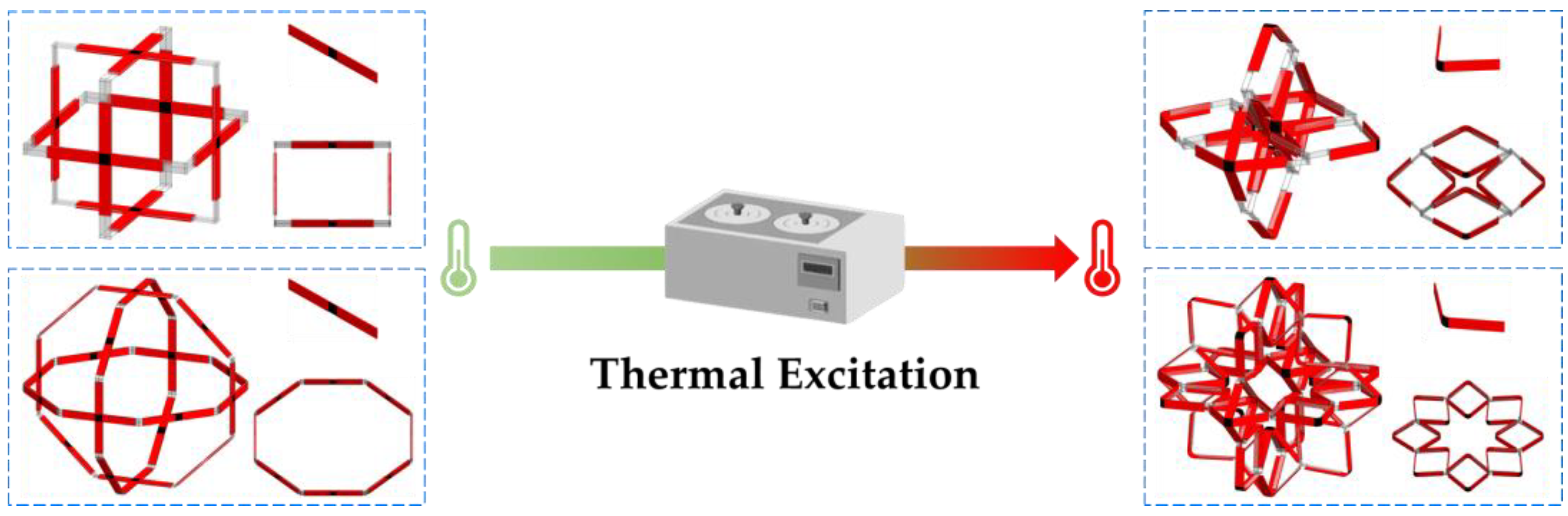
An SFSM with pre-stressed response properties under predetermined thermal excitation was designed, and its compositions and operating modes are shown in Figure 1. When no thermal excitation was applied, the SFSM showed an unfolded state. At this moment, the volume of space reached its maximum value. When the predetermined thermal excitation was applied, the SFSM gradually self-folded under pre-stress. Eventually, the volume of space reached its minimum value.
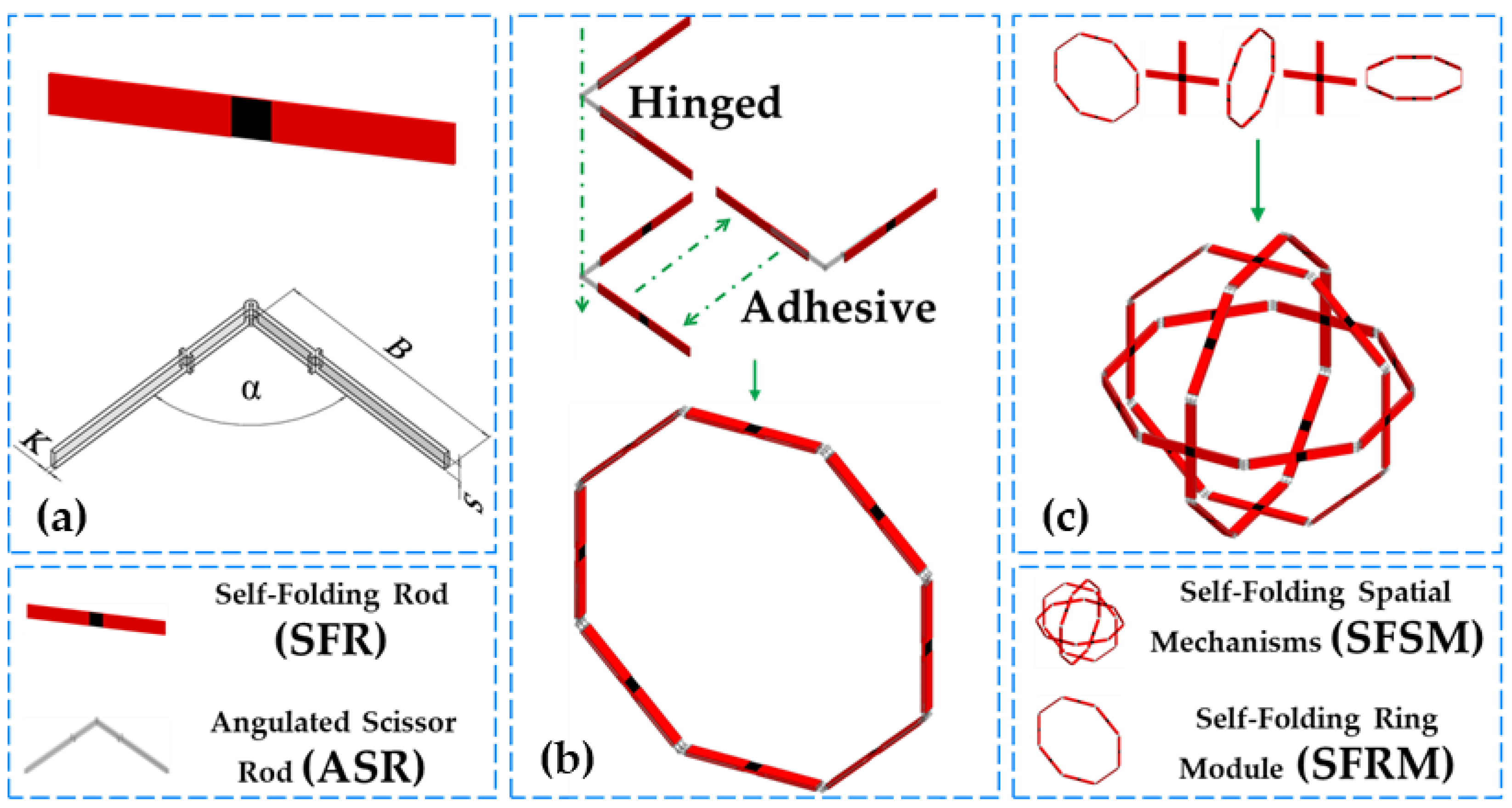
The pre-stressed response properties of the SFSM under predetermined thermal excitation were crucial to realizing the change in the volume of space. For this purpose, the SFR and ASR that constituted the SFSM were designed, as shown in Figure 2a. The ASR controlled the construction, shrinkage ratios, and morphing patterns of the SFSM based on a pre-designed structure and geometric arrangement. The SFR enabled the SFSM to obtain a self-folding feature based on the pre-stressed response properties under predetermined thermal excitation. When thermal excitation was applied, the SFR changed from an unfolded state to a folded state according to the pre-stressed response model and drove the ASR to fold the SFSM during this process.
2.2. Construction Method and Self-Folding Motion Principle
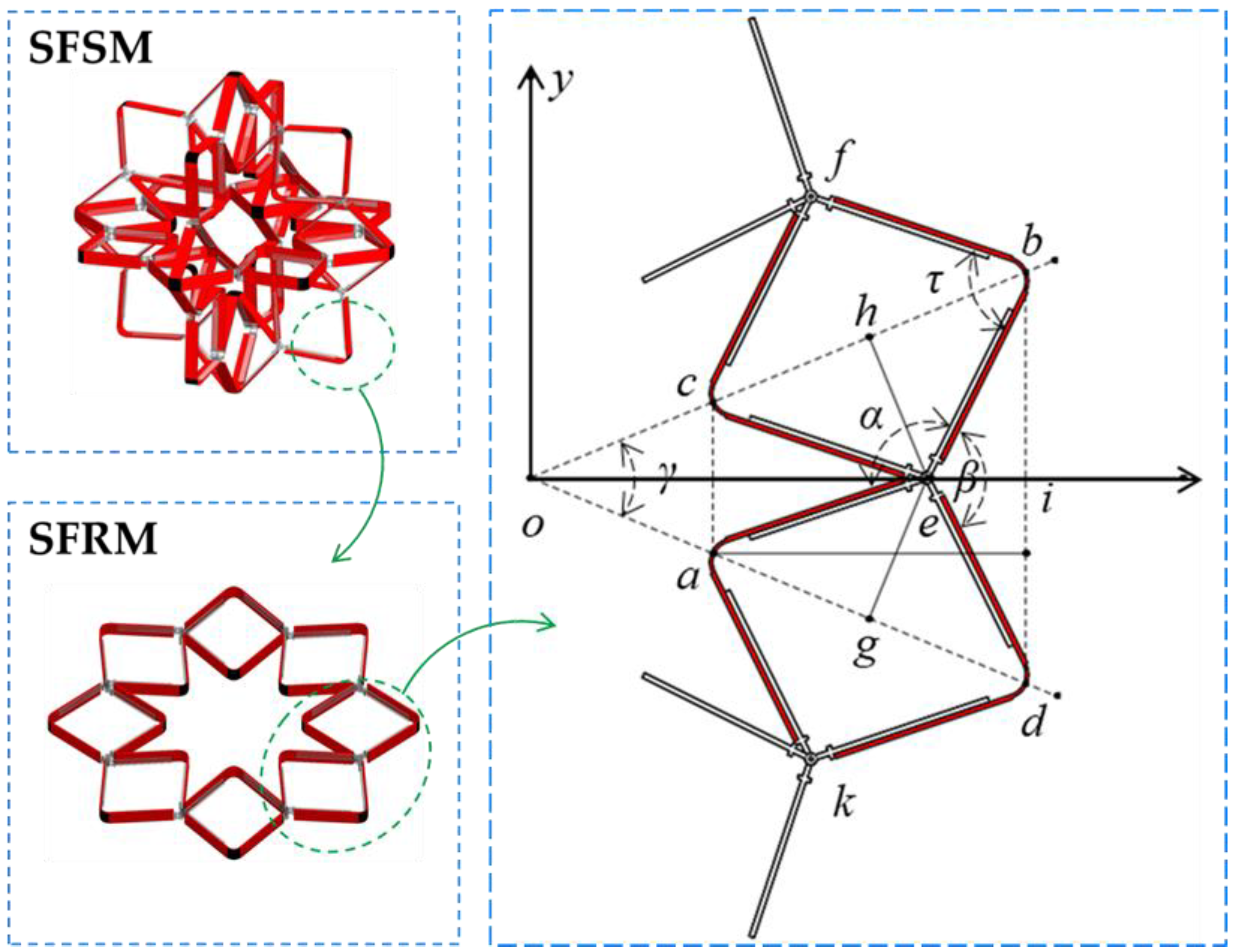
As shown in Figure 3, the self-folding ring module (SFRM) was extracted from the constructed SFSM, and the ASR and SFR were extracted from the SFRM to establish a rectangular coordinate system. Point e was the hinge point, and point o was the intersection of a and d with the b and c lines. Two vertical lines from point e to ob and od were made, and points h and g were the feet of perpendiculars. Combined with Figure 3, we can prove that:
∵ ∠aeb = ∠ced = α
∵ ∠cea is the common angle
∴ ∠ceb = ∠aeb − ∠aec = ∠ced − ∠cea = ∠aed
∵ ce = ed = ae = eb
∴ △ceb and △aed are congruent isosceles triangles
∵ The lines eh and eg are the perpendicular bisector of △ceb and △aed
∴ △ceh ≅ △beh ≅ △aeg ≅ △deg
∵ ∠ceh = ∠beh = ∠aeg = ∠deg
∴ 2∠ceh + ∠cea = 2∠aeg + ∠cea = α
∴ ∠ceh + ∠cea + ∠aeg = α
∵ ∠ohe + ∠oge + ∠heg + ∠hog = 2π
∵ ∠ohe = ∠oge = π/2
∴ ∠hog = ∠coa = π − α
Let m be the number of rod groups (containing 2m SFRs and 2m ASRs) required to construct the SFRM.
∵ γ = ∠hog = ∠coa = 2π/m
We know that:
Based on the above proof, it is known that the angle γ in a circular segment (such as angle dob) corresponding to each group of ASRs is always constant, and its value is only related to m. The value of m also determines the top angle α of the ASR. An SFRM can thus be constructed using m rod groups.
The construction method is as follows: the ASR is hinged, and the SFR adheres to the ASR. The serially connected SFRs and ASRs construct the SFRM in the two-dimensional plane, as shown in Figure 2b. As shown in Figure 2c, the paralleled adhered SFRMs construct the SFSM in three-dimensional space. Table 1 lists the SFRMs and SFSMs constructed at different values of m.
The previous paragraph detailed the SFSM’s construction method. On this basis, the principle of self-folding motion was explained. In order to explain this principle, it is necessary to identify the motion features of the SFSM.
The SFRM motion features are first discussed. The ASR’s relative rotation caused by the SFR’s self-folding realizes the SFRM’s self-folding. The SFR drives the ASR motion, and the hypothesis is that the motion is created by face contact between the ASRs extending at both ends. As a result, the SFR can be thought of as a planar revolving pair.
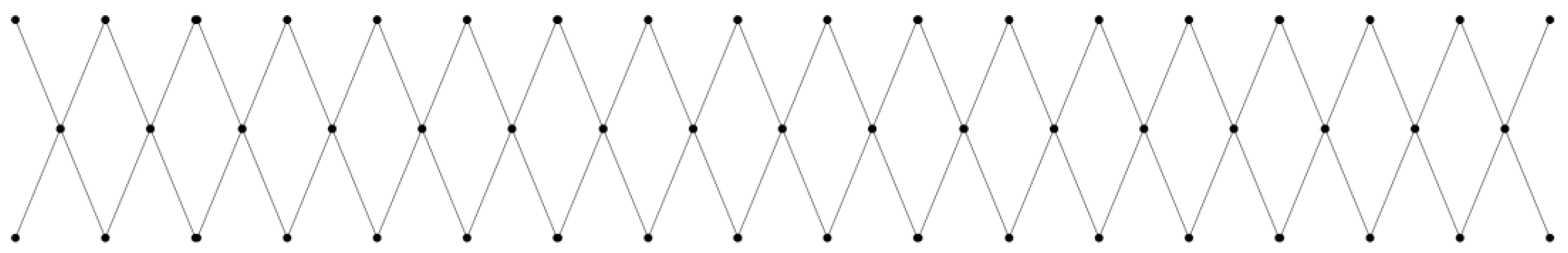
As shown in Figure 4, an SFRM was used with an m value of 12 to cut and expand into a plane kinetic chain along the line connecting points o and d.
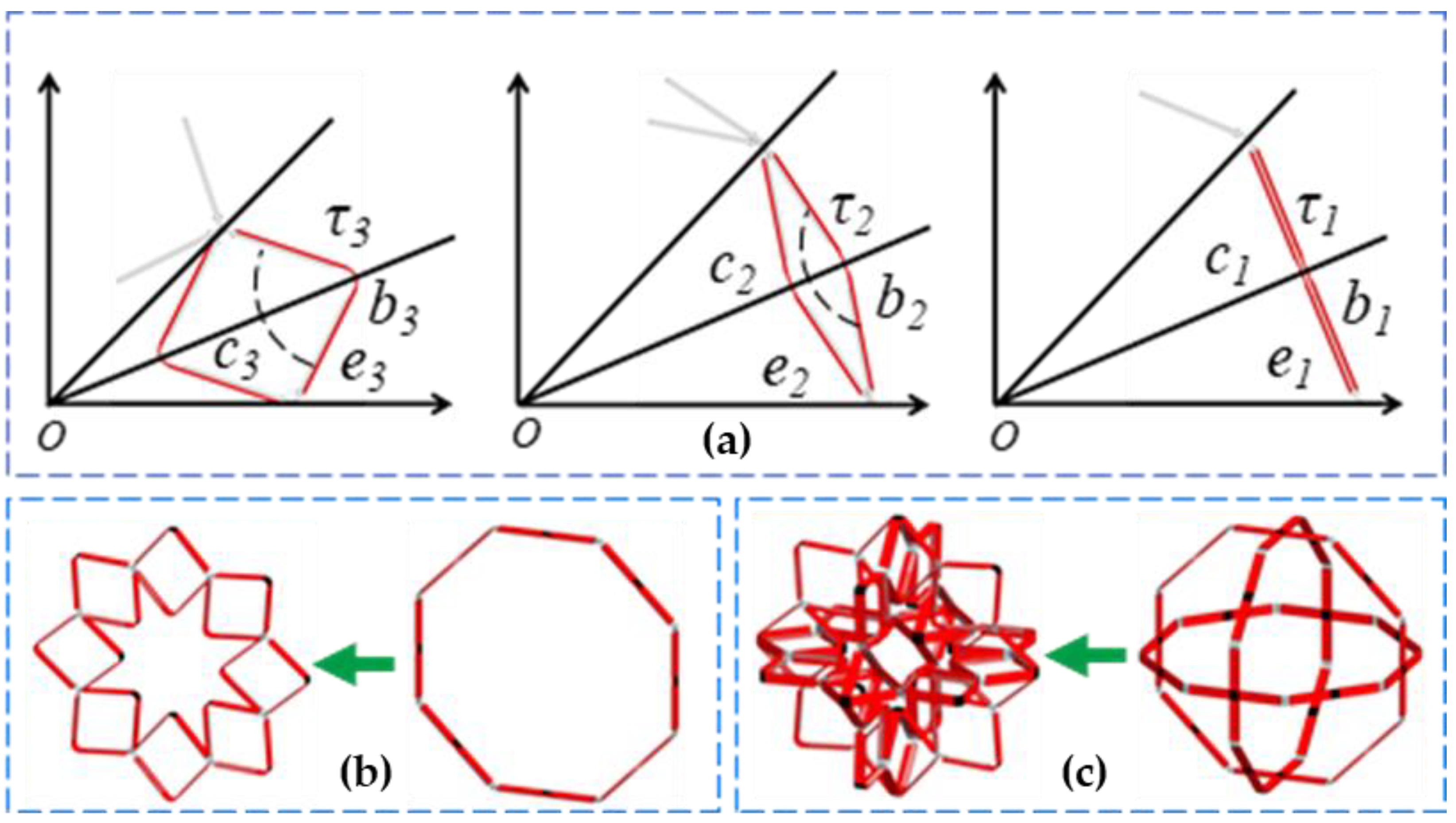
Applying the loop connectivity matrix (LCM), we know that:
Let F be the degree of freedom. According to Equation (2), we concluded that the SFRM has a single degree of freedom.
The SFSM motion features are discussed next. The SFSM can be regarded as a three-dimensional structural combination of SFRMs perpendicular to each other, overlapping in the center of a circle. Li [24] analyzed similar mechanisms using screw theory and demonstrated that when the sub-kinetic chain has a single degree of freedom, the spatial mechanisms composed of the sub-kinetic chain have zero degrees of freedom in the fully expanded and contracted state and have a single degree of freedom during the motion. Thus, the SFSM also has similar degrees of freedom. As shown in Figure 5a, the SFR folds under predetermined thermal excitation, and the folding angle change process is τ1→τ2→τ3. SFR midpoints b and c move along the line ob, which drives the hinge point e between the ASR along the line eo movement. As shown in Figure 5b, the above process is presented as a contraction of serially connected SFRs and ASRs around the center of the SFRM’s circle under predetermined thermal excitation. As shown in Figure 5c, the above process is presented as a contraction of mutually perpendicular SFRMs around the center of the SFSM’s sphere under predetermined thermal excitation.
2.3. Mathematical Model
As shown in Figure 3 and Figure 5, let the length of lines ae, ce, be and de be B. The angle fbe is defined as folding angle τ.
The mathematical model of the SFSM in the self-folding motion was derived:
The length of line bd is:
For the triangle bod, according to the law of cosines, we know that:
In the triangle bod, it is easy to know that ob is equal to od; bringing Equation (4), we know that:
Letting Equation (3) equal Equation (5), we can solve the following:
When the folding angle reaches a minimum value, the SFSM is folded. Let Rmin be the minimum circumscribed circle radius. Let τmin be the minimum folding angle. In the triangle bod, it is easy to know that Rmin is equal to ob and od; bringing Equation (7), we know that:
In the triangle obe, it is easy to know that:
Bringing Equation (9) into Equation (8), we know that:
The length of the line oe is:
Bringing Equation (4) into Equation (10), we can deduce:
When the folding angle reaches a maximum value, the SFSM is unfolded. Let Rmax be the maximum circumscribed circle radius. Let τmax be the maximum folding angle. In the triangle obe, it is easy to know that Rmax is equal to oe; bringing Equation (12), we know that:
In the triangle obe, it is easy to know that:
Bringing Equation (14) into Equation (13), we know that:
Its structural shrinkage ratio is:
From the above proof and calculations, we concluded that the m value not only controls the construction and shrinkage ratio of the SFSM but also controls the morphing patterns of the SFSM based on the folding angle τ. As a result, the ASR controls the construction, morphing, and shrinkage ratio of the SFSM by geometric arrangement based on a pre-designed number of m rod groups.
Conventional mechanical design methods considering only a single geometric feature and topology are not feasible for SFSM because of the pre-stressed response properties of controlling structural transformations under predetermined thermal excitation. This type of structure’s design is not to be considered only in terms of construction methods and the principle of self-folding motion. Further research on the pre-stress response model based on 4D-printed materials and fabrication is needed to enable SFSM to obtain self-folding features based on the pre-stress response properties under predetermined thermal excitation.
3. Pre-Stressed Response Model
In this section, we began researching the pre-stressed response model of the SFSM. The SFR was a component with an integrated motion actuator and driver, which enabled the SFSM to obtain a self-folding feature based on the pre-stressed response properties under predetermined thermal excitation.
This section contains three subsections on the pre-stressed response model. First, the thermodynamic properties of the 4D-printed materials used to make the SFR were characterized. Second, the morphing patterns of the SFR were coupled by the combination and design of multi-material prefabricated components according to the self-folding design requirements of the SFSM and the characterization of material thermodynamic properties. Finally, in order to achieve the required driving and folding of the spatial mechanisms as much as possible, research on the folding morphing influences based on the pre-stress was carried out.
3.1. Characterization of Material Properties
The thermodynamic properties of different materials might be utilized to print and control the SFR. In addition, this work used predetermined thermal excitation as a means of self-folding activation. As a result, material property tests were conducted to characterize the material’s thermodynamic properties and provide a relevant basis for subsequent research.
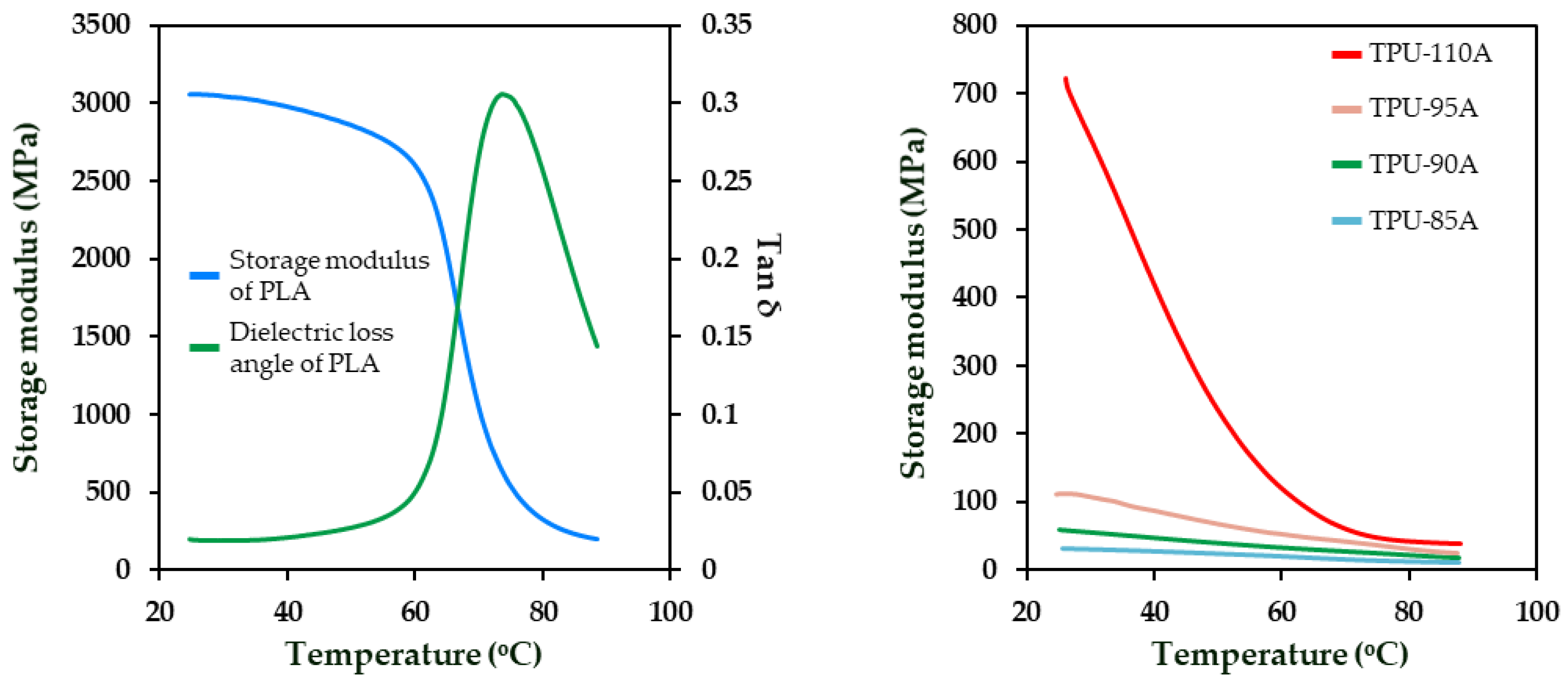
We selected four commercial elastomer materials based on thermoplastic polyurethane (TPU) (Dake, China) and one polymer material, polylactic acid (PLA) (Raise Premium, China). The dynamic thermodynamic properties of these five materials were analyzed using a dynamic thermo-mechanical analyzer (DMA-Q800, United States) in selected tensile mode. The practical test length of the PLA and TPU printed filaments was 10 mm, and the diameter was 1.75 mm. The test loading temperature range was 25 °C to 90 °C. The accuracy of the temperature loading was ±0.2 °C. The temperature rise rate was controlled at 2 °C/min during the test. The dynamic axial stretching rate was 1 Hz. The dynamic thermo-mechanical analyzer (DMA) test results included the changes in the storage modulus G and dielectric loss angle Tanδ with temperature T, as shown in Figure 6. The Ti, Tg, and Th of PLA were 61.96, 68.02, and 73.57 °C, respectively. The G values for PLA corresponding to the three temperatures were 2458.76, 1375.28, and 637.75 MPa. The subscripts i, g, and h represented the beginning, transition, and end of PLA’s glass transition phase. Similarly, the DMA test results for TPU showed that the Tg of TPU was below room temperature, and G values of TPU decreased slowly with the increasing temperature.
3.2. Coupling of Morphing Patterns
The SFR drove the SFSM to self-fold by bending patterns based on the pre-stressed response properties under predetermined thermal excitation. Therefore, this section discusses how to couple the SFR to produce bending by combining and designing multi-material prefabricated components according to the design requirements of the SFSM and the characterization of material thermodynamic properties.
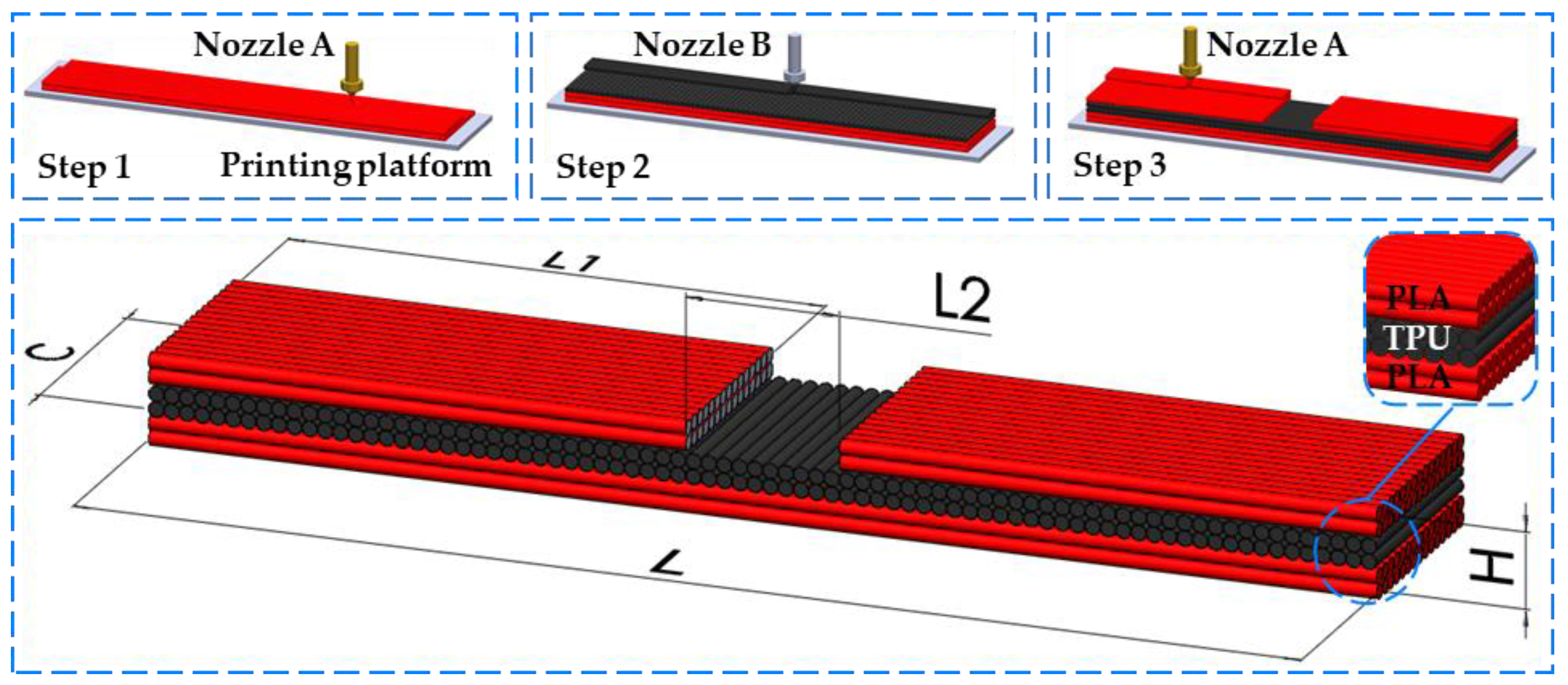
As shown in Figure 7, the SFR was designed and printed utilizing TPU and PLA material by fused deposition modeling. This structure consisted of six layers, four of which were continuous and two that were split. The separation layers were designed to control the deformed part’s width and compensate for the edge bending generated by the PLA layer.
First, how the SFR obtained the pre-stress response properties under predetermined thermal excitation was explained. Heating and squeezing the PLA filament during the printing process caused the polymer chains to stretch and align in the direction of that path and subsequently generate stress. They were stored in the printed material due to the constraining effect of the printing platform or previous layer. They were fixed layer by layer as the printing process cooled. When each PLA layer was removed from the printer and reheated above its glass transition temperature Tg, the pre-stress stored in the PLA layer was released and shortened along the printing direction while expanding slightly along the other two directions.
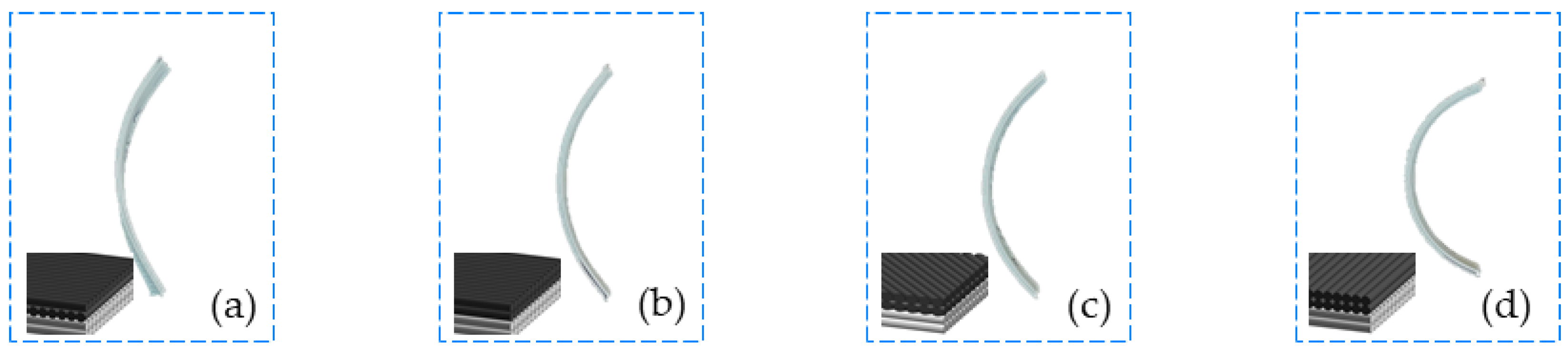
Second, it was explained how to couple the SFR to produce bending by combining and designing multi-material prefabricated components in accordance with the SFSM design requirements and the characterization of material thermodynamic properties. PLA layers with unidirectional filling patterns exhibit anisotropic morphing behavior, resulting in more significant anisotropic morphing behavior than multidirectional filling patterns [25,26]. For this reason, all PLA layers in this work were always printed in the same orientation. However, only single-layer PLA structures were used, which could produce unpredictable flex-torsion. The DMA test found that the glass transition temperature of TPU was generally lower than room temperature. The TPU elastic modulus was relatively stable over the Th temperature range from room temperature to PLA, and it was assumed that it could not contract; it could only bend and slightly elongate. These properties were used, combining PLA and TPU in layers to print the SFR, which coupled the unpredictable morphing of PLA into bending. Although the TPU only played a restricted role in the SFR, its filling patterns still influenced bending. In order to investigate the influence of TPU filling patterns on morphing, the separation layer of SFR was removed. TPU filling patterns had a more noticeable influence on morphing when the separation layer was removed. As shown in Figure 8, another of our experimental results revealed that when the filling patterns of the TPU layers were perpendicular to the PLA layers and there was no separation layer, the structure exhibited the best bending.
3.3. Morphing Influence Based on Pre-Stress
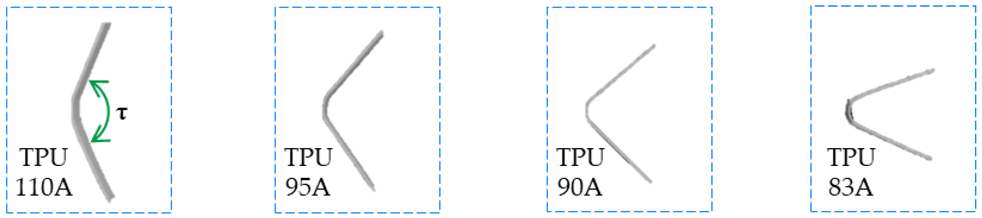
Following the SFR-coupled bending, the influence of pre-stress on the SFR’s folding under predetermined thermal excitation was investigated in this section to fulfill the requisite driving and self-folding. The previous discussion showed that storing and restricting pre-stress in the SFR influences bending. Therefore, if the morphing influence of the SFR was to be obtained, it was necessary to research the influence of the pre-stressed restricting capability of the TPU and the pre-stress storage capability of the PLA on the change in its folding angle τ.
First, the pre-stressed restricting capability of the TPU is discussed. Four SFRs were printed and experimented with using four TPU materials. These SFRs were printed using a fused deposition modeling printer (Raise E2, Shanghai, China). Hot water was chosen as the activation medium for the experiments to ensure a uniform, accurate and fast heat application on the SFRs [27]. The glass transition temperature Tg of the PLA was selected from Figure 5, and the printing speed for all materials was set to 30 mm/s. The temperature setting of the water bath device (LICHEN-HH4, Shanghai, China) was kept constant. All SFRs used for the experiments were kept in water, and heating was stopped when they no longer exhibited visual signs of deformation. The printing parameters, structure size, and experimental parameters are shown in Table 2.
Through experiments, it was found that TPU materials with higher storage modulus have highly pre-stressed restricting capability, causing weaker SFR drive and minor variation in folding angle τ, as shown in Figure 9. According to another experimental result in the literature [28,29], the lower the percentage of hard polymer segments supporting TPU materials, the more difficult it was to print them. After considering the printing quality and material properties, this work chose a single TPU-90A material to print the SFR.
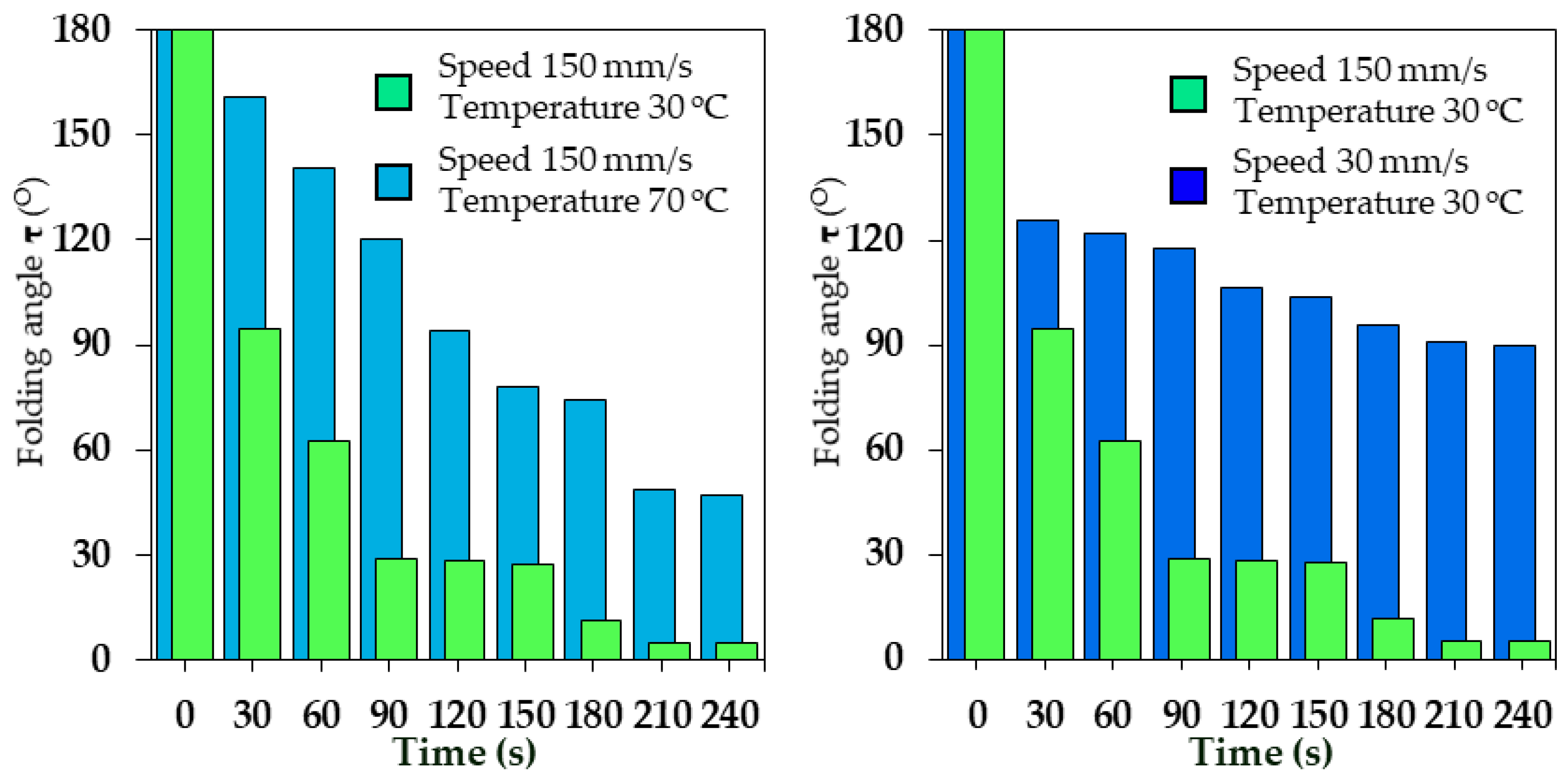
Second, the pre-stress storage capability of the PLA is discussed. On the one hand, adjusting the printing speed caused different stretching of the PLA material during the extrusion process, resulting in different levels of pre-stress stored in the material. On the other hand, adjusting the printing platform temperature caused different mobility of the polymer chains in the PLA, resulting in different fixation times of their macroscopic shapes and stress relaxation effects. It also caused a difference in the levels of pre-stress stored.
Three experimental groups were established. The first group of 45 SFRs was printed with the printing platform temperature set to 30 °C and the PLA layer printing speed set to 150 mm/s. The second group of 45 SFRs was printed with the printing platform temperature set to 30 °C and the PLA layer printing speed set to 30 mm/s. The third group of 45 SFRs was printed with the printing platform temperature set to 70 °C and the PLA layer printing speed set to 150 mm/s. Only the above parameters were changed in the three experimental groups, and the other parameters were the same as in Table 1.
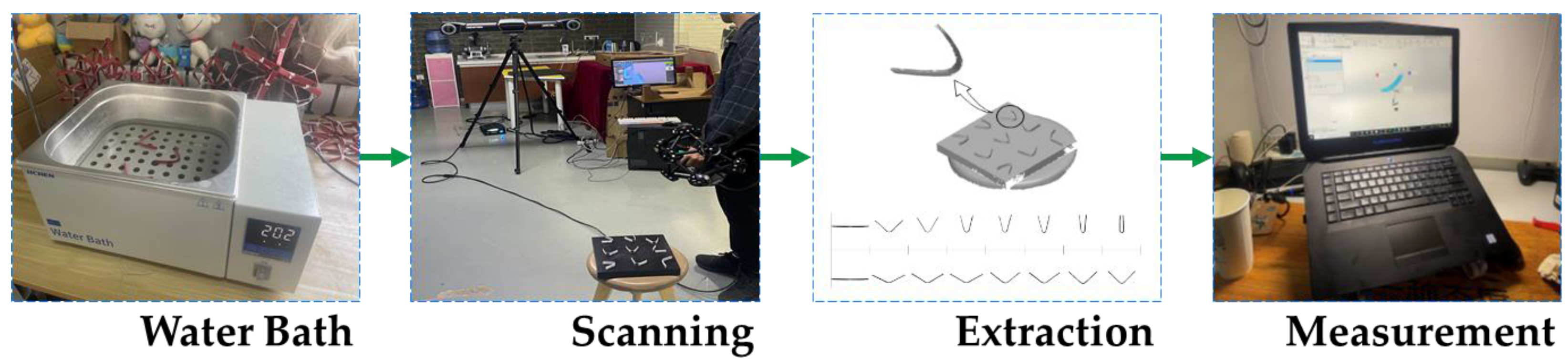
In each experimental group, five SFRs for each group were heated simultaneously in a water bath, and another group was heated for increasing intervals of 30 s. At the end of the time, the SFR was removed from the constant temperature water bath, cooled to room temperature, and placed on a scanning test bench to capture the surface shape. An optical 3D scanner (MetraSCAN 3D, Lévis, QC, Canada) was used to measure the folding angle τ after morphing. The collected data were combined to create corresponding 3D models for each experimental group to assess the experimental results more accurately and quantitatively. Figure 10 depicts the entire experimental process.
The averages of the measured results of the folding angle τ are shown in Figure 11. The experimental results indicated the following:
- Printing PLA materials at faster print speeds allowed for more significant stretching of the polymer chains during extrusion. Therefore, under the condition that the printing platform temperatures were constant, this approach allowed the SFR to maintain higher pre-stress, resulting in a broader range of folding angle variations and stronger drive capability.
- Printing PLA materials on a lower temperature printing platform could quickly lock the polymer chains in a stretched state. Therefore, under the condition that the printing speed parameters were constant, this approach allowed the SFR to maintain higher pre-stress, resulting in a broader range of folding angle variations and stronger drive capability.
- The folding angle of the SFR gradually decreased as the water bath time increased. Throughout the process, the self-folding was most evident within 2 min. After 3 min, the SFR samples no longer produced significant self-folding, and their folding angles remained stable. Therefore, the drive capability of the SFR continuously decreased with the increased water bath time.
4. Manufacture and Experiments
This section consists of two subsections. First, two SFSMs with m values of 4 and 8 were printed and assembled and named S4 and S8, respectively. In this class of mechanisms, S4 was chosen for its unique characteristics, while S8 was chosen for its universal characteristics. Second, the feasibility of self-folding of the SFSM was experimentally verified.
4.1. Printing and Assembly of the SFSM
The ASR and SFR were printed using a dual-nozzle fused deposition modeling printer (Raise E2, Chengdu, China) and assembled into SFSM. The S4 was constructed with 24 ASRs and 24 SFRs. The S8 was constructed with 48 ASRs and 48 SFRs.
The printing process for the ASR is described first because it controlled the constructions, shrinkage ratios, and morphing patterns of the SFSM based on a pre-designed structure and geometric arrangement. The ASR was printed using a common high-temperature resistant polycarbonate material (Raise, Premium PC). The ASR’s length B was first determined. Equation (1) was then used to calculate the top angle α of the ASR based on the selected value of m. Equations (6) and (11) were used to calculate the theoretical maximum and minimum radius of the circumscribed circles based on the above two parameters. Because of the thickness S limitation, these mechanisms did not reach the theoretical shrinkage ratio. The specific printing parameters for the ASR in this work are shown in Table 3.
The printing process for the SFR is described second because it enabled the SFSM to obtain a self-folding feature based on the pre-stressed response model. According to the experimental results, printing PLA materials on a lower temperature printing platform at faster print speeds allowed the polymer chains to stretch more significantly during extrusion and lock in the stretched state quickly, which helped to maintain high pre-stress to ensure that the SFR obtained significant driving and folding. The specific printing parameters of the SFR in this work are shown in Table 4.
4.2. Experiments with the SFSM
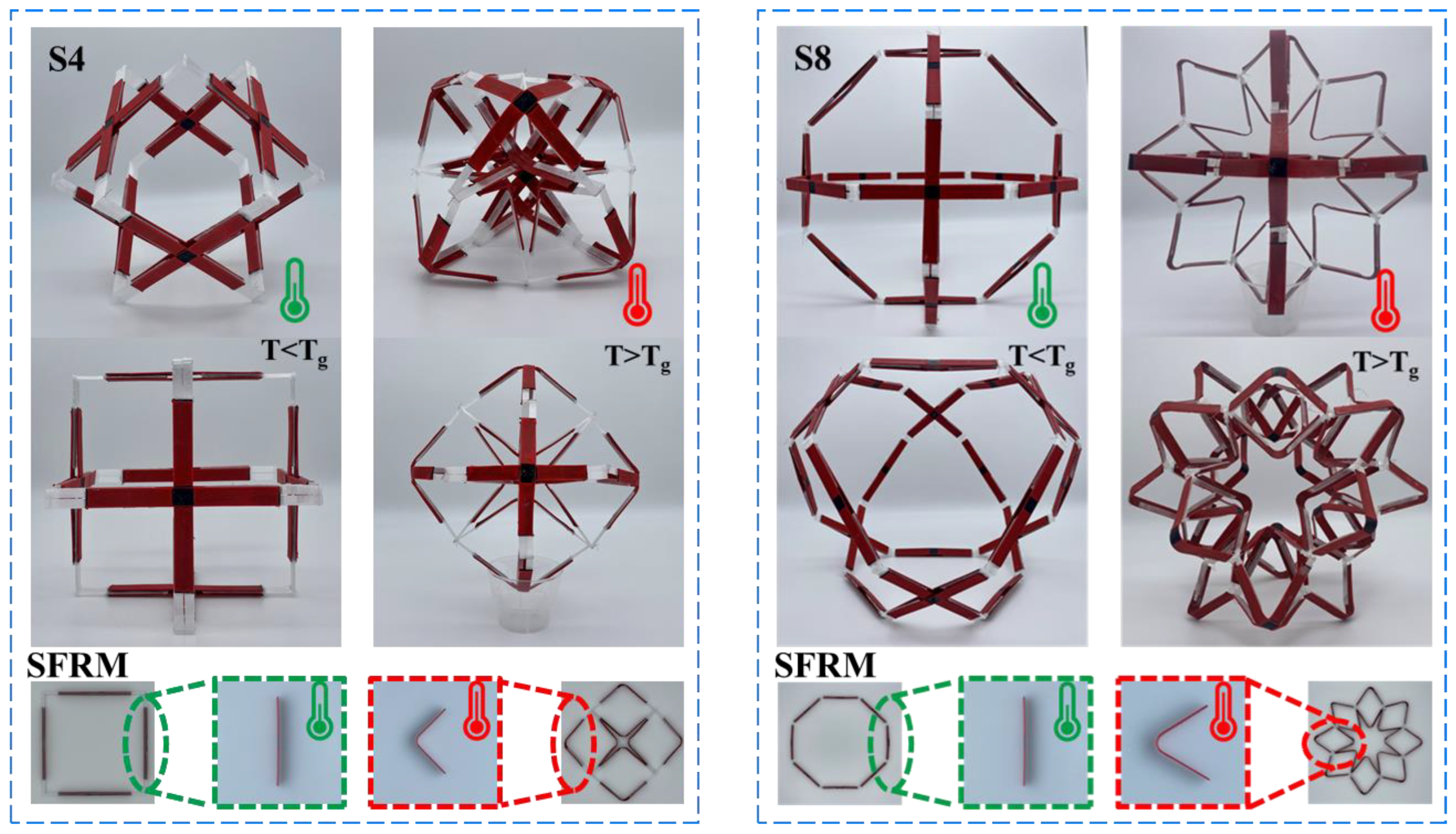
The S4 and S8 were assembled. The experimental verification conditions and parameter settings were consistent with previous experiments. The experimental results are shown in Figure 12.
As shown in Figure 12a, the volume of S4 reached its maximum before thermal excitation (T < Tg), and the circumscribed circle radius Rmax was about 100.39 mm. After thermal excitation (T > Tg), the SFR was self-folding, and the SFRM contracted. At this moment, the S4′s volume reached its minimum value, and the circumscribed circle radius Rmin was about 96.47 mm. It should be noted that the actual and theoretical shrinkage ratio χ of this mechanism was 1 and about 0.96, respectively. The radius of the S4′s circumscribed circle changed negligibly during the self-folding process. However, after self-folding, its structure was significantly transformed. The square hexahedron made up of squares was transformed into an orthoctahedron made up of equilateral triangles.
As shown in Figure 12b, the volume of S8 reached its maximum before thermal excitation (T < Tg), and the circumscribed circle radius Rmax was about 146.38 mm. After thermal excitation (T > Tg), the SFR was self-folding, and the SFRM contracted. At this moment, the S8′s volume reached its minimum value, and the circumscribed circle radius Rmin was about 129.13 mm. The actual and theoretical shrinkage ratio χ of this structure was about 0.71 and 0.88, respectively.
The experimental results demonstrated that the SFSM could realize the self-folding adjustment of the volume ratio under the predetermined thermal excitation, verifying the correctness and feasibility of the design and pre-stressed response model and theoretical analysis.
5. Conclusions
Based on 4D printing technology, SMSFs with different shrinkage ratios were prepared via fused deposition modeling, and the correctness and feasibility of the design, pre-stress response model, and theoretical analysis were verified by experiments.
Compared with the existing 4D printing technology, which lacks a paradigmatic design method in the application field, this work organically combined the conventional mechanical structure design with materials and fabrication via fused deposition modeling. A design was proposed based on the mutual integration of structural design and morphing control. It is expected that this design will introduce a novel paradigm of 4D printing technology into conventional mechanical design and have considerable application prospects in the design of spherical radar calibration mechanisms.
The material’s distribution and geometric parameters were changed by fused deposition modeling to impart its pre-stressed response properties under predetermined thermal excitation and construct SFSMs with different shrinkage ratios. On the one hand, the structural components and kinematic pairs are combined into one, which effectively solves the problems of complex structure and excessive kinematic pairs in conventional spatial mechanical design. On the other hand, the drive and control system are combined into one, and the pre-stress response property under thermal excitation brought by 4D printing is used to replace the complex drive control system in the conventional spatial mechanical design while also bringing the novel feature of self-folding. This is not found in the conventional spatial mechanism.
In future work, more external thermal excitation sources (such as electric heating, optical heating, and magnetic field heating) will be introduced into the SFSM for regulation and experiment. Additionally, the hinges in the existing structures will be gradually replaced by smart materials to eventually realize SFSMs without mechanical connections.
Author Contributions
Conceptualization, W.Z. and D.L.; Data curation, W.Z.; Methodology, W.Z. and D.L.; Formal analysis, W.Z. and D.L.; Resources, D.L.; Investigation, W.Z. and D.L.; Software, W.Z.; Project administration, D.L.; Supervision, D.L.; Validation, D.L. and W.Z.; Writing—original draft preparation, W.Z.; Writing—review and editing, W.Z. and D.L. All authors have read and agreed to the published version of the manuscript.
Funding
This research was funded by the National Natural Science Foundation of China (Grant No. 52175019), and Beijing Natural Science Foundation of China (Grant No. 3212009).
Data Availability Statement
Not applicable.
Conflicts of Interest
The authors declare that there are no conflict of interest.
References
- Escrig, F.; Valcarcel, J.P.; Sanchez, J. Deployable cover on a swimming pool in Seville. J. Int. Assoc. Shell Spat. Struct. 1996, 37, 39–79. [Google Scholar]
- Freire-Tellado, M.J.; Muñoz-Vidal, M.; Pérez-Valcárcel, J. Bias deployable grids with horizontal compound scissor-like elements: A geometric study of the folding/deployment process. Int. J. Space Struct. 2021, 37, 22–36. [Google Scholar] [CrossRef]
- Dai, J.S.; Li, D.; Zhang, Q.; Jin, G. Mobility analysis of a complex structured ball based on mechanism decomposition and equivalent screw system analysis. Mech. Mach. Theory 2004, 39, 445–458. [Google Scholar] [CrossRef]
- Zhao, N.; Luo, Y.; Shen, Y. Design, modeling and validation of a deformable capsule-like crawling robot based on scissor elements. SSRN Electron. J. 2022. submitted. [Google Scholar] [CrossRef]
- Li, R.; Chen, H.; Choi, J.H. Topological assembly of a deployable Hoberman flight ring from DNA. Small 2020, 17, 124502–124511. [Google Scholar] [CrossRef]
- Li, R.; Sun, X.; Chen, Y.; Yao, Y.; Ding, X. Design and analysis of reconfigurable deployable polyhedral mechanisms with straight elements. J. Mech. Robot. 2019, 11, 44502–44510. [Google Scholar] [CrossRef]
- Hoberman, C. Tranformable: Building Structures that Change Themselves. In Building Dynamics: Exploring Architecture of Change, 1st ed.; Branko, K., Vera, P., Eds.; Routledge: London, UK, 2015; Volume 3, pp. 101–126. [Google Scholar]
- Cai, J.; Xu, Y.; Feng, J. Kinematic analysis of Hoberman’s linkages with the screw theory. Mech. Mach. Theory 2013, 63, 28–34. [Google Scholar] [CrossRef]
- Lak, A.; Asefi, M. A new deployable pantographic lunar habitat. Acta Astronaut. 2022, 192, 351–367. [Google Scholar] [CrossRef]
- Cao, W.; Xi, S.; Ding, H.; Chen, Z. Design and kinematics of a novel double-ring truss deployable antenna mechanism. J. Mech. Des. 2021, 143, 124502–124511. [Google Scholar] [CrossRef]
- Zhao, N.; Luo, Y.; Wang, G.; Shen, Y. A deployable articulated mechanism enabled in-flight morphing aerial gripper. Mech. Mach. Theory 2022, 167, 104518. [Google Scholar] [CrossRef]
- Dong, K.; Li, D.; Xue, X.; Xu, C.; Wang, H.; Gao, X. Workspace and accuracy analysis on a novel 6-UCU bone-attached parallel manipulator. Chin. J. Mech. Eng. 2022, 35, 2–13. [Google Scholar] [CrossRef]
- Wang, R.; Dai, J. Design and analyses of a novel plane-space polyhedral reconfigurable metamorphic mechanism. J. Mech. Eng. 2013, 49, 29–35. [Google Scholar] [CrossRef]
- Jia, P.; Li, D.; Zhang, Y.; Yang, C. A novel reconfigurable parallel mechanism constructed with spatial metamorphic four-link mechanism. Proc. Inst. Mech. Eng. Part C J. Mech. Eng. Sci. 2022, 236, 4120–4132. [Google Scholar] [CrossRef]
- Kang, X.; Dai, J. Theoretical difficulties and research progresses of mechanism reconfiguration in mechanisms -evolution connotation, furcation principle, design synthesis and application of metamorphic mechanisms. Chin. Mech. Eng. Soc. 2020, 31, 57–71. [Google Scholar]
- Coimbra, M.R.; Barbosa, T.P.; Vasques, C.M. A 3D-printed continuously variable transmission for an electric vehicle prototype. Machines 2022, 10, 84. [Google Scholar] [CrossRef]
- Zhang, W.; Ge, Z.; Li, D. Evolution and emerging trends of 4D printing: A bibliometric analysis. Manuf. Rev. 2022, 9, 30. [Google Scholar] [CrossRef]
- Khalid, M.Y.; Arif, Z.U.; Noroozi, R.; Zolfagharian, A.; Bodaghi, M. 4D printing of Shape Memory Polymer Composites: A review on fabrication techniques, applications, and future perspectives. J. Manuf. Process. 2022, 81, 759–797. [Google Scholar] [CrossRef]
- Khalid, M.Y.; Arif, Z.U.; Ahmed, W.; Umer, R.; Zolfagharian, A.; Bodaghi, M. 4D printing: Technological developments in robotics applications. Sens. Actuators A Phys. 2022, 343, 113670. [Google Scholar] [CrossRef]
- Arif, Z.U.; Khalid, M.Y.; Noroozi, R.; Sadeghianmaryan, A.; Jalalvand, M.; Hossain, M. Recent advances in 3D-printed polylactide and polycaprolactone-based biomaterials for tissue engineering applications. Int. J. Biol. Macromol. 2022, 218, 930–968. [Google Scholar] [CrossRef]
- Khalid, M.Y.; Arif, Z.U.; Ahmed, W. 4D printing: Technological and manufacturing renaissance. Macromol. Mater. Eng. 2022, 307, 2200003. [Google Scholar] [CrossRef]
- Arif, Z.U.; Khalid, M.Y.; Ahmed, W.; Arshad, H. A review on four-dimensional (4D) bioprinting in pursuit of advanced tissue engineering applications. Bioprinting 2022, 27, e00203. [Google Scholar] [CrossRef]
- Arif, Z.U.; Khalid, M.Y.; Zolfagharian, A.; Bodaghi, M. 4D bioprinting of smart polymers for biomedical applications: Recent progress, challenges, and future perspectives. React. Funct. Polym. 2022, 179, 105374. [Google Scholar] [CrossRef]
- Li, D.; Dai, J.; Zhang, Q.; Jin, G. Mobility of a kind of metamorphic mechanism-magic ball. Chin. J. Mech. Eng. 2002, 38, 12–16. [Google Scholar] [CrossRef]
- van Manen, T.; Janbaz, S.; Zadpoor, A.A. Programming 2D/3D shape-shifting with hobbyist 3D printers. Mater. Horiz. 2017, 4, 1064–1069. [Google Scholar] [CrossRef] [PubMed] [Green Version]
- Kačergis, L.; Mitkus, R.; Sinapius, M. Influence of fused deposition modeling process parameters on the transformation of 4D printed morphing structures. Smart Mater. Struct. 2019, 28, 105042. [Google Scholar] [CrossRef]
- Hu, G.F.; Damanpack, A.R.; Bodaghi, M.; Liao, W.H. Increasing dimension of structures by 4D printing shape memory polymers via fused deposition modeling. Smart Mater. Struct. 2017, 26, 125023. [Google Scholar] [CrossRef]
- Qi, H.J.; Boyce, M.C. Stress–strain behavior of thermoplastic polyurethanes. Mech. Mater. 2005, 37, 817–839. [Google Scholar] [CrossRef]
- Kim, K.; Park, J.; Suh, J.-H.; Kim, M.; Jeong, Y.; Park, I. 3D printing of multiaxial force sensors using carbon nanotube (cnt)/thermoplastic polyurethane (TPU) filaments. Sens. Actuators A Phys. 2017, 263, 493–500. [Google Scholar] [CrossRef]
Figure 1.
Schematic of the design and operating mode of the SFSM.

Figure 2.
Schematic of the construction process of the SFSM: (a) the SFR and the ASR, (b) construct of the SFRM, (c) construct of the SFSM (left to right by order of appearance).
Figure 2.
Schematic of the construction process of the SFSM: (a) the SFR and the ASR, (b) construct of the SFRM, (c) construct of the SFSM (left to right by order of appearance).

Figure 3.
Schematic of the rectangular coordinate system of the ASRs and SFRs.

Figure 4.
Plane kinetic chain with m value of 12.

Figure 5.
Schematic of self-folding: (a) SFR and ASR self-folding, (b) SFRM self-folding, (c) SFSM self-folding.
Figure 5.
Schematic of self-folding: (a) SFR and ASR self-folding, (b) SFRM self-folding, (c) SFSM self-folding.

Figure 6.
DMA test results: Storage modulus and dielectric loss angle of PLA (left) and storage modulus of TPU (right).
Figure 6.
DMA test results: Storage modulus and dielectric loss angle of PLA (left) and storage modulus of TPU (right).

Figure 7.
Schematic of the manufacturing process of the SFR.

Figure 8.
Experiments on the effect of different filling patterns of TPU layer on bending: (a) TPU material 90° cross alignment, (b) TPU 90° side-by-side alignment, (c) TPU material 45° cross alignment, (d) TPU 180° side-by-side alignment.
Figure 8.
Experiments on the effect of different filling patterns of TPU layer on bending: (a) TPU material 90° cross alignment, (b) TPU 90° side-by-side alignment, (c) TPU material 45° cross alignment, (d) TPU 180° side-by-side alignment.

Figure 9.
Experiment on the influence of TPU layer pre-stressed restricting capability on the change in folding angle τ.
Figure 9.
Experiment on the influence of TPU layer pre-stressed restricting capability on the change in folding angle τ.

Figure 10.
The 3D optical scanning processes.

Figure 11.
Experiment on the influence of PLA pre-stress storage capability on the change in folding angle τ.
Figure 11.
Experiment on the influence of PLA pre-stress storage capability on the change in folding angle τ.

Figure 12.
The self-folding experiment with the SFSM.


Table 1.
Construction of SFRMs and SFSMs at different values of m.
| m | Theoretical Shrinkage Ratio | Folded SFRM | Unfolded SFRM | Unfolded SFSM |
|---|---|---|---|---|
| 4 | 1 |  |  |  |
| 8 | 0.71 |  |  |  |
| 12 | 0.5 |  |  |  |
| 16 | 0.38 |  |  |  |
Table 2.
Sample structure size and printing and experimental parameters of the SFR.
| Structure Size/[mm] | H | C | L2 | L1 | L |
| 1.2 | 10 | 10 | 45 | 100 | |
| Printing parameters | Layer height (mm) | 0.2 | |||
| Infill amount | 100% | ||||
| Extrusion width (mm) | 0.4 | ||||
| Nozzle diameter (mm) | 0.4 | ||||
| Printing platform temperature (°C) | 30 | ||||
| PLA printing temperature (°C) | 235 | ||||
| TPU printing temperature (°C) | 200 | ||||
| Experimental parameters | Activation medium | Water | |||
| Water bath temperature (°C) | 68 | ||||
| Water bath time (s) | ≥180 | ||||
Table 3.
Manufacturing parameters for the ASR.
| Structure Parameters | |||||
|---|---|---|---|---|---|
| Number of groups m | Top angle α (o) | Side length B (mm) | Thickness K (mm) | Width S (mm) | |
| 4 8 | 90 135 | 60 | 3 | 5 | |
| Printing Parameters | |||||
| Printing platform temperature (°C) | Printing speed (mm/s) | Layer height (mm) | Infill amount | Extrusion width (mm) | Printing temperature (°C) |
| 110 | 60 | 0.2 | 15% | 0.4 | 235 |
Table 4.
Manufacturing parameters for the SFR.
| Structure Parameters | ||||||||
|---|---|---|---|---|---|---|---|---|
| Height H (mm) | Width C (mm) | Separation layer width L1 (mm) | Separation layer spacing distance L2 (mm) | Length L (mm) | ||||
| 1.2 | 10 | 45 | 10 | 100 | ||||
| Printing parameters | ||||||||
| Layer height (mm) | Infill amount | Extrusion width (mm) | Nozzle diameter (mm) | PLA | TPU | Platform temperature (°C) | ||
| Speed (mm/s) | Temperature (°C) | Speed (mm/s) | Temperature (°C) | |||||
| 0.2 | 100% | 0.4 | 0.4 | 150 | 235 | 30 | 200 | 30 |
Disclaimer/Publisher’s Note: The statements, opinions and data contained in all publications are solely those of the individual author(s) and contributor(s) and not of MDPI and/or the editor(s). MDPI and/or the editor(s) disclaim responsibility for any injury to people or property resulting from any ideas, methods, instructions or products referred to in the content. |
© 2023 by the authors. Licensee MDPI, Basel, Switzerland. This article is an open access article distributed under the terms and conditions of the Creative Commons Attribution (CC BY) license (https://creativecommons.org/licenses/by/4.0/).
Share and Cite
MDPI and ACS Style
Zhang, W.; Li, D. A 4D-Printed Self-Folding Spatial Mechanism with Pre-Stressed Response Properties. Machines 2023, 11, 121. https://doi.org/10.3390/machines11010121
AMA Style
Zhang W, Li D. A 4D-Printed Self-Folding Spatial Mechanism with Pre-Stressed Response Properties. Machines. 2023; 11(1):121. https://doi.org/10.3390/machines11010121
Chicago/Turabian StyleZhang, Wencai, and Duanling Li. 2023. "A 4D-Printed Self-Folding Spatial Mechanism with Pre-Stressed Response Properties" Machines 11, no. 1: 121. https://doi.org/10.3390/machines11010121
Note that from the first issue of 2016, this journal uses article numbers instead of page numbers. See further details here.