
A New Modeling Approach for Parameter Design of Stewart Vibration Isolation System Integrated into Complex Systems

1
Changchun Institute of Optics, Fine Mechanics and Physics, Chinese Academy of Sciences, Changchun 130000, China
2
University of Chinese Academy of Sciences, Beijing 100049, China
3
Chang Guang Satellite Technology Co., Ltd., Changchun 130000, China
*
Author to whom correspondence should be addressed.
Machines 2022, 10(11), 1005; https://doi.org/10.3390/machines10111005
Submission received: 23 July 2022
/
Revised: 24 October 2022
/
Accepted: 26 October 2022
/
Published: 31 October 2022
(This article belongs to the Special Issue Vibration and Acoustic Analysis of Components and Machines)
Abstract
:A possible application for multi-dimensional vibration isolation is the Stewart vibration isolation system (SVIS). An innovative parameter design method is provided in this research, in which the SVIS is equated to an elastic node with stiffness-damping characteristics of six degrees of freedom. This paper addresses parameter design as a crucial issue for the SVIS integrated in large and complex systems. Two levels make up most of the content. First, the stiffness synthesis and deconstruction processes of the SVIS are inferred and demonstrated, suggesting that the elastic node may be used to quickly and effectively identify the stiffness-dumping of the SVIS. A system of parameter design flow for the SVIS integrated into complex systems is suggested based on the theory. A Stewart platform prototype is next created. To validate the hypothesis, FEM simulations and dynamics tests are carried out sequentially. The simulation findings demonstrate that the prototype’s six natural frequencies depart from the theory within 1%, and the frequency response curves closely match the theory. According to test results, the Z-directional resonant frequency falls 1.7% below predictions. The X/Y-direction frequency response curves include certain poor characteristics caused by structural clearances, but overall trends support the notion. The study offers theoretical direction for SVIS-integrated optimization design in complex systems.
1. Introduction
Scholars have conducted a significant amount of research on the theoretical modeling, structural design, and control system development of this fascinating mechanism [1] since the 1960s, when the Gough–Stewart parallel mechanism was first postulated [2]. The Stewart parallel mechanism has evolved into one of the most cutting-edge structures in the multi-dimensional vibration isolation field as a result of its distinctive kinematic properties. The Stewart Vibration Isolation System (SVIS) is now offered for a variety of uses in a number of industries, including vehicles, precision instrumentation, and aerospace [3,4,5,6].
Most recent research of SVIS is primarily oriented on active vibration isolation design and optimization that are applied for multidimensional vibration isolation applications, including the active vibration isolation unit development [7,8,9], active control strategy design [10,11,12]. By comparison, much less research has been performed on the overall stiffness-damping characteristics of SVIS. However, the active way makes little effect on high-frequency disturbances [6,13], with the limitation of actuator performance and control system delays. Therefore, in certain cases, the SVIS stiffness-damping characteristics are still required to suppress the high-frequency disturbances through the passive way. As: certain advanced spacecraft working in the space environment, the precision loads equipped are very sensitive to high-frequency disturbances [14,15]. These high-frequency disturbances (frequencies above 100 Hz) inevitably caused by the attitude control flywheel severely affect the performance of the spacecraft, which can hardly be addressed by active vibration isolation. This leads to the necessity of research on the passive vibration isolation characteristics of SVIS. Since the key parameters, covering the structure and stiffness-damping of strut, determine the vibration isolation performance of SVIS, reasonable parametric modeling is highly required to guide researchers completing the parameter design and optimization.
In previous studies, the Lagrangian method [16,17,18] and the Newton–Euler method [19,20,21] have most frequently been applied for dynamic analysis of the Stewart platform. However, the dynamic equations of SVIS systems achieved by the above methods are usually adopted in implicit form, leading to an absence of a significant functional relationship between the system mechanical properties and key parameters, hence they are not feasible for direct application to the parameter design of SVIS. To address this issue, some scholars have developed corresponding dynamic parametric models in explicit form for the analysis of the Stewart platform. Jiang has developed equations to relate the six-order natural frequencies to the parameters of the Stewart platform under undamped conditions [22]. Behrouz established a fully parametric model around the model behavior of the Stewart platform, in which parametric formulations of eigenvectors, stiffness, damping, and Jacobian matrices are presented in terms of design variables [23]. In addition, the overall stiffness characteristics, as the main aspect affecting the vibration isolation performance and dynamic behavior of SVIS, have been studied around relating them to the parameters. Chen completely developed the modeling of instantaneous stiffness for Stewart platforms through Jacobian-based approaches [24]. Regarding the stiffness isotropy, Yao and Bandyopadhyay have separately established the parametric equations for the stiffness of the Stewart platform [25,26]. Kumar developed a stiffness model for contour generation application to identify the trajectory with maximum stiffness for complex contours [27]. In previous research, the parametric equations were mainly constructed around a certain mechanical property, which fails to reflect the mechanism quite obviously, whereby the system parameters affect the overall stiffness-damping characteristics. Therefore, it is infeasible to directly take the overall stiffness-damping parameters as variables for a solution, which is not conducive to the integrated design of SVIS in the complex system.
The designability of SVIS makes it suitable for a variety of situations in which a high performance of vibration isolation is required. In order to achieve the best isolation performance, it is usually necessary to obtain the optimal parametric solutions of the SVIS. Many scholars have conducted in-depth research around the optimization design of SVIS parameters under different conditions. Yang and Shyam applied SVIS for the micro-vibration isolation of a spacecraft payload, and they adopted various parametric optimization methods to optimize the structural parameters of the Stewart platform, so that the SVIS has the minimum range of natural frequency distribution for the first six orders [28,29]; Biag optimized the structural parameters of the Stewart platform through a genetic algorithm (GA) without changing the active control parameters and analyzed the influence of structural parameters on the vibration isolation effect through numerical analysis methods [30]; Li proposed a dual quaternion method to derive the Jacobi matrix of the Stewart platform and optimized the platform parameters to obtain the best isotropic performance, so that the motion-coupling characteristics of the platform were improved [31]. Singh also carried out corresponding research on the structural parameters around the isotropy of the Stewart platform [32,33]. Although the research on SVIS parametric modeling and parametric optimization have matured, it mainly focused on rigid-body systems, in which the base platform part connected to lower platform and the payload part connected to the upper platform are regarded as rigid bodies. As for complex systems in reality, the coupling characteristics introduced by the flexibility of the base platform part or the payload part connected to SVIS may not be ignored, hence the previous parametric modeling and optimization design methods are not applicable anymore. It is necessary to propose a simple and efficient parameter-modeling method to improve the flexibility of parameter setting for SVIS integration, which can facilitate the integrated optimization design of SVIS in a complex system.
In this paper, a method to simplify SVIS modeling is proposed. Rigorous theoretical derivation proves that the SVIS can be equated to an elastic node with stiffness in six degrees of freedom (6-DOF), and the parameters of the structure as well as the stiffness-damping of the vibration isolation units can be solved inversely through the elastic node. This modeling method simplifies and directly reveals the relationship between the system parameters and the overall stiffness-damping characteristics from a new perspective. Further, the overall stiffness-damping parameters of SVIS can be integrated directly into the entire system as a few simple variables through the equivalent conversion, which provides a great convenience for the parameter design of SVIS integrated into complex systems. To validate the correctness of the equivalent modeling method, a UPS Stewart vibration isolation platform (SVIP) prototype was developed. The key dynamic characteristics of the SVIP prototype were achieved by FEM simulations and dynamics tests. Simulation results show that the error of the first six orders of natural frequencies of the SVIP do not exceed 1%, and the frequency response curves highly coincide with the theory; test results show that the resonant frequency of the SVIP is lower than the theoretical result by 1.7% in the Z direction, and certain differences between frequency response curves exist between tests and the theory in the X/Y direction, but the overall trend agrees with the theory. Despite the discrepancies that exist in the test results comparing to the theoretical and simulation results, the equivalence theory of the elastic node proposed in this paper is still considered to be reasonable. The inconsistencies of the results are concluded to be caused by the structural clearances, which can be resolved by the subsequent structural improvement of the platform prototype.
The state of the art of this paper is the innovative modeling method that equates SVIS to an elastic node, which provides an effective technical means for the integrated analysis of SVIS applied in complex systems. Related parameter modeling methods are original and have not been proposed before. The research content of this paper is divided in to four parts. Section 2 proposes an equivalence method of the elastic node, and a theoretical justification for the method is provided. Section 3 introduces the FEM simulations and experimental tests of the developed Stewart vibration isolation platform, and the findings are thoroughly evaluated in this section. Section 4 concludes the work of the paper. This paper will contribute to the further development of parameter design for SVIS for analysis and strongly support the development of SVIS optimal design in a large and complex system.
2. Theoretical Analysis of SVIS
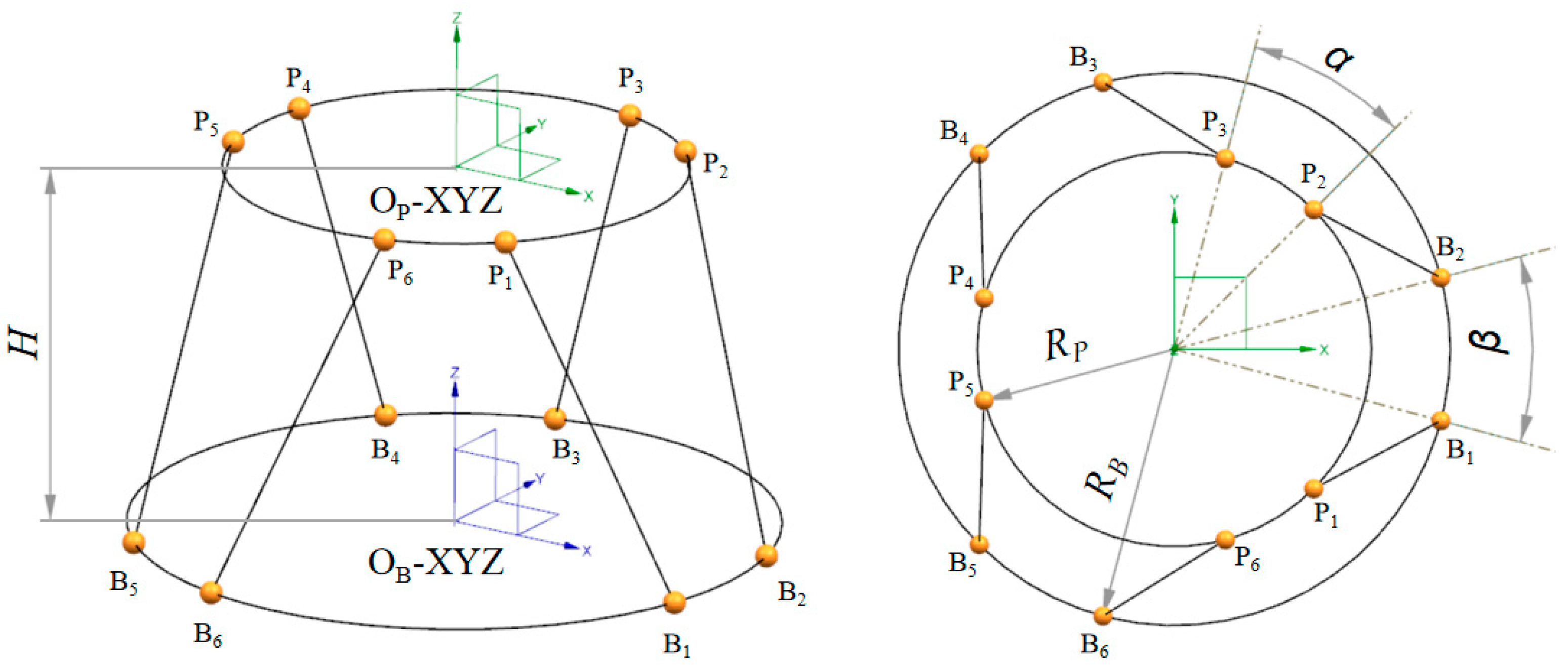
The structure diagram of the Stewart platform is shown in Figure 1. The geometric configuration is defined by five structural parameters: the base platform’s joint-point circle’s radius , the payload platform’s joint-point circle’s radius , the distribution angle of the payload platform’s joint-point and the base platform’s joint-point , as well as the height between the payload platform’s and base platform’s joint-point circles .
2.1. Dynamic Theory of Stewart Vibration Isolation Platform
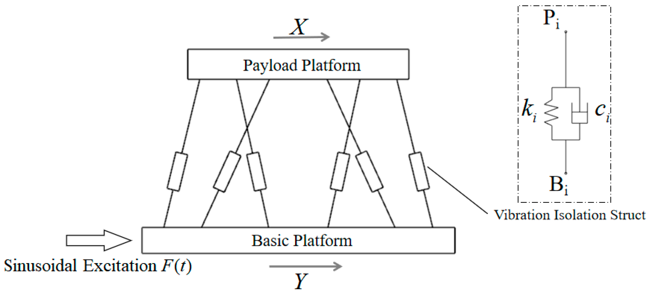
As indicated in Figure 2, when the Stewart platform is used to isolate vibrations, the disturbances are typically input from the base platform and output from the payload platform. Here, we assume the general displacement of the payload platform is , the general displacement of the base platform is , and the dynamics formula of the system can be written as follows:
where: ,
indicates the platform’s general mass matrix, indicates the platform’s general stiffness matrix, and indicates the general damping matrix, respectively, where the struts’ stiffness and damping are taken to be linear. The following can be inferred from the derivation:
where: , () denotes the stiffness (damping) coefficient of -th strut. The matrix is the kinematic Jacobi matrix of the Stewart platform.
Assume that the moving coordinate system OP-XYZ and the fixed coordinate system OB-XYZ have the same beginning coordinate directions. The origins of OB-XYZ and OP-XYZ, which are fixed to the base platform and payload platform, respectively, and the joint-point circles of both the base platform and the payload platform, respectively, are where the two objects are located. The following is a description of the Jacobi matrix in this situation for the overall displacement between the payload platform and the moving struts:
where denotes the unit direction vector of the -th strut in the static coordinate system OB-XYZ; denotes the rotation transformation matrix from the coordinate system OP-XYZ to the coordinate system OB-XYZ; denotes the position vector of -th joint point on the payload platform in the coordinate system OP-XYZ.
The establishment of the coordinate system above is often applied when focusing on the kinematics of the Stewart platform itself. However, the design of vibration isolation system’s places mainly concentrates on the dynamics of the isolated object and pays little attention to the payload platform itself during the actual engineering. In order to facilitate the vibration isolation design around the isolated object, as well as to expressly conduct the subsequent theoretical analysis, we extend the position of the moving coordinate system OP-OXYZ along the Z-axis.
Based on Equation (1), we transfer the OP-XYZ coordinate system a set distance along the Z-axis, resulting in the joint-point circle center of the payload platform having the Z-axis coordinate of in OP-XYZ. The Stewart platform’s Jacobi matrix can be rewritten as follows by the derivation:
Here, we reexamine the general stiffness matrix and the general damping matrix . It is assumed that the stiffness and damping of the isolation struts are linear, and the stiffness and damping of all struts are the same (i.e.,, ). In this case, the stiffness matrix and the damping matrix have the same form as . Now, we define the dynamic characteristic matrix and the matrix is expressed as the following form:
The global stiffness and damping properties of SVIS are clearly reflected in the matrix , and future study will be focused on this matrix in the section that follows.
2.2. Dynamic Characteristic Matrix
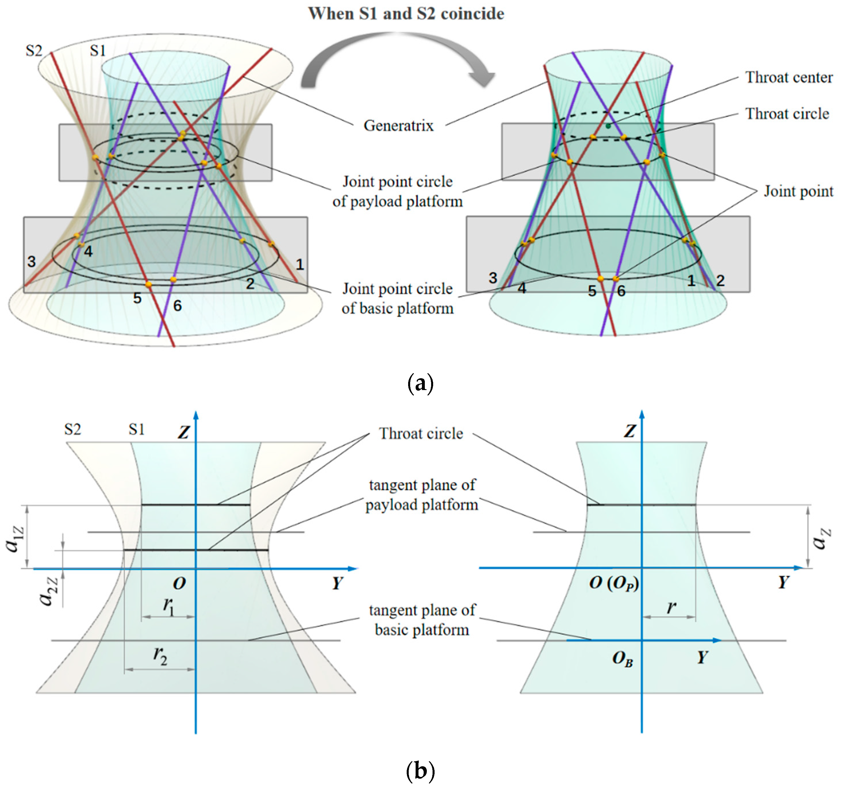
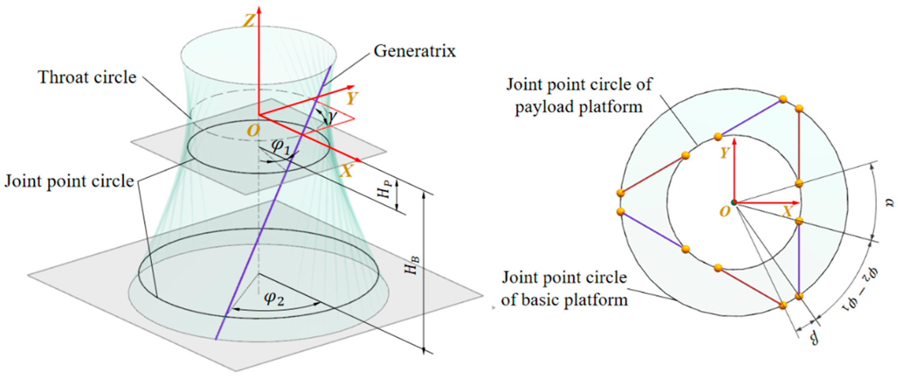
Jiang [34] adopted a modeling method whereby the structural parameters of generalized Gough–Stewart configuration are presented lying on a circular hyperboloid of one sheet. There are a pair of hyperboloids of one sheet S1 and S2 shown in Figure 3, whose surface equations are described as:
In the Stewart parallel mechanism, the two circular hyperboloids’ surfaces can be thought of as having six evenly spaced struts, and the straight lines where the struts are located can be thought of as the hyperboloids’ generatrices. According to Figure 3, the odd-numbered struts (1, 3, 5) and the even-numbered struts (2, 4, 6) are distributed on the hyperboloids S1 and S2, respectively. The hyperboloids can be combined with two horizontal parallel planes to form a pair of circles. The placements of the joint points are determined by the junction points of the straight line corresponding to the struts and the pairs of circles, which are the joint-point circles of the payload platform and base platform, respectively. According to the Plücker coordinates of the six generatrices, the Jacobi matrix of the Stewart parallel mechanism can be directly expressed as [34]:
where the functions of and are derived as:
where:
Here, and are the coefficients that determine S1 and S2, which also denote the throat’s radius of the hyperboloid S1 and S2; and are the coefficients that determine S1 and S2; and are the Z-axis coordinates of the center of S1 (S2); and , respectively, represent the unit vectors for the struts 1 and 2; denotes the angle between the generator and the x-axis.
The Stewart parallel mechanism, which is the classical configuration that is predominantly investigated in this study, depicts the situation in which both hyperboloids S1 and S2 coincide. The following are due to the coincidence of S1 and S2: , , , .
Once the fixed coordinate systems OB-XYZ are established, the coordinate system O-XYZ can now be thought of as the moving coordinate system OP-XYZ, as shown in Figure 3b. Both coordinate systems correspond to the coordinate systems mentioned above. In the figure, and denote the Z-coordinates of the throat center in the coordinate system OP-XYZ and OB-XYZ, respectively. In this case, there is . Based on this, substituting Equation (7) into Equation (5) produces:
where: .
Here, the vector can represent the unit direction vector of any strut.
This section details the derivation of the dynamic characteristic matrix . Through the above elaboration, the design of stiffness for the SVIS can be translated into the design of the matrix .
2.3. Equivalent Stiffness Analysis of the SVIS
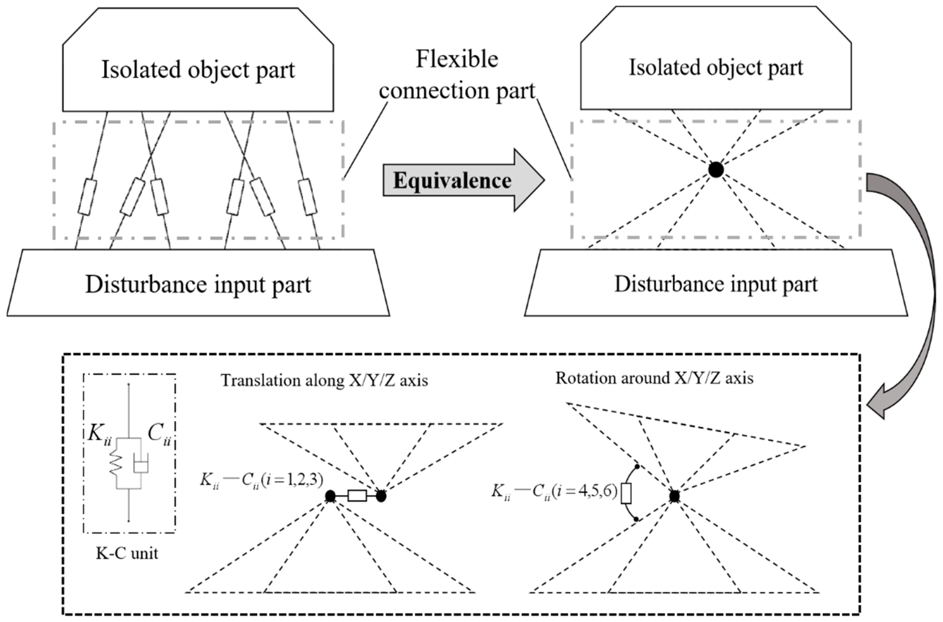
In the scenario of vibration isolation design, the whole system can be considered as consisting of three parts: an isolated object part, a disturbance input part, and a flexible connection part, as shown in Figure 4. The payload platform and base platform are shown here as the isolated object part and disturbance input part, respectively, and the flexible connection part is represented by the six vibration isolation struts that link the two platforms together.
As mentioned in Section 2.1, the coordinate systems OP-XYZ and OB-XYZ are separately fixed to the parts of the payload and the base platform. The stiffness matrix of the flexible connection part is , which reflects the stiffness characteristics between the OP-XYZ and OB-XYZ in six degrees of freedom.
It can be found from Equation (5) and Equation (8) that when (i.e., the origin of the coordinate system OP-XYZ coincides with the throat center of the hyperboloid of one sheet), there is: . In this situation, becomes a diagonal matrix, so the stiffness matrix can be rewritten as the that decouples completely in 6-DOF. Further, the coordinate systems OP-XYZ and OB-XYZ (or the payload and base platform part) can be treated as if they were connected by six parallel springs of six directions, which are concentrated in one point, as shown in Figure 4.
In summary, the position of the elastic node is the throat center of the hyperboloid corresponding to the SVIS, and its connection stiffness in six directions is ; can be determined by the Equation (8). Similarly, the damping of the SVIS can be processed as well.
The SVIS can be compared to an elastic node with 6-DOF stiffness-damping properties through the aforementioned elaboration, and the stiffness in each direction is equal to the appropriate diagonal element in the stiffness matrix . The dampening of the SVIS can also be treated in a similar manner. Furthermore, it is noteworthy that there are a few key characteristics of the elastic node’s stiffness that serve as guidelines for vibration isolation design. Here, we provide more justifications. The following conclusions are drawn from the study of Equation (8):
- , is a diagonal matrix. It indicates that the stiffness of the elastic node is independent in 6-DOF.
- , . This indicates that the stiffness of the elastic node is symmetric about the X and Y axes.
- , and the three element values are only determined by and . This indicates that the sum of the translational stiffness along the X/Y/Z-axis is a fixed value, which depends only on the angle between the generatrix of the hyperboloid and the XOY plane.
- , and the three element values are not only determined by and , but also by . It is indicated that the sum of the rotational stiffness around the X/Y/Z-axis is a fixed value, which not only depends on , but is also proportional to the square of the radius of the throat circle .
By this point, the descriptions for the equivalent transformation of the SVIS are accomplished in this section.
2.4. Stiffness Decomposition
This section of the paper will specify the process of reverse conversion from the stiffness center to the SVIS. Assuming that there is such a system containing the isolated object A and the disturbance input part B, which has multi-dimensional vibration isolation requirements, as a result, the SVIS is prepared to be applied for this situation.
Prior to that, the parameters of the stiffness matrix and the position need to be determined according to the performance indicators of the isolated object. This process can be accomplished by appropriate methods of iterative optimization or numerical calculations. The parameter inverse solution can be carried out after determining the elastic nodes’ parameters. Firstly, the general stiffness matrix is divided by the stiffness coefficient , representing the stiffness value of a single strut, so that the dynamic characteristic matrix . The value of k can be determined by equation . Due to being decoupled, is a diagonal matrix, and the value of each diagonal element is . Next, the diagonal element is brought into Equation (8) to solve the parameters of the corresponding hyperboloid, by which we sequentially obtain the radius of hyperboloid throat circle and the unit vectors’ parameters of generatrix and . Then, the angle between the generatrix and the horizontal plane can also be determined by the equation . The hyperboloid corresponding to the SVIS can also be fully identified by combining the condition that the location of the elastic node is the location of the throat-circle center of the hyperboloid. Afterward, a pair of suitable planes parallel to the XOY plane are chosen to intersect the hyperboloid in accordance with the actual structure and other design boundary requirements, and the two resulting cross-section circles are the upper and lower joint-point circles corresponding to the SVIS. Then, the locations of the corresponding struts are determined by choosing three pairs of generatrices that are symmetrically distributed around the hyperboloid’s central axis. The intersection points of the generatrices and the cross-section circles serve as the joint points for the payload platform and the base platform.
Finally, the design parameters of the hyperboloid are further derived according to the geometric relationship, so that the corresponding structural parameters of the SVIS can be determined. The following is a list of parametric solution formulas that the author has offered; they are not all exclusive:
where:
Here, denotes the angle between the generatrix and the plane XOY; and denote the angle between the intersection point’s horizontal position vectors and the plane XOZ; and respectively, represent the height position of the tangent planes. The meanings of the parameters are presented in Figure 5.
Moreover, for better application in actual engineering, the following additional notes are essential for the parameter design of SVIS:
- Theoretically, can be selected arbitrarily from the range (0°,60°), and when is determined, the other value can also be determined.
- The distribution angle of the struts around the Z-axis has no effect on the stiffness characteristics of the SVIS.
- After the position of the stiffness center is determined, the position parameters of the tangent plane corresponding to the joint-point circles of the payload (base) platform only determine the positions of joints, without affecting the stiffness characteristics of the SVIS.
This section has elaborated the process of parameter conversion from equivalent elastic nodes to SVIS. Further, the parameter design of SVIS can be translated into the design of the equivalent elastic node.
2.5. Discuss
In this paper, it is indicated that the SVIS can be equated to an elastic node with stiffness-damping characteristics of 6-DOF through the theoretical derivation. The equivalence method can express the stiffness characteristics of the SVIS in a relatively clear and concise way while retaining the original stiffness characteristics. Theoretically, under the satisfaction of specific constraints, the elastic node’s parameter selection range encompasses all feasible SVIS parameters, making it possible to apply parameter optimization to identify the best solution among all conceivable values. In addition, the existing formulas for parameter conversion eliminate the need for complex function calculations during the conversion between the elastic node and SVIS, making the design of the SVIS in practical engineering much more effective.
It is worth mentioning that the proposed equivalent modeling method cannot only be adopted for general numerical methods for the parameter design of SVIS under rigid body conditions, but the equated elastic node model can be fully integrated with the FEM method compared with the previous SVIS parameter model, which allows for better parameter design of SVIS in complex flexible systems. In order to better represent the value of the proposed equivalent modeling method in engineering applications, its usage is extended and explained in this section. Taking the vibration isolation design of a remote-sensing satellite as an example, the integrated optimization design of the SVIS’s equivalent parameter model under the satellite system is introduced by the following contents.
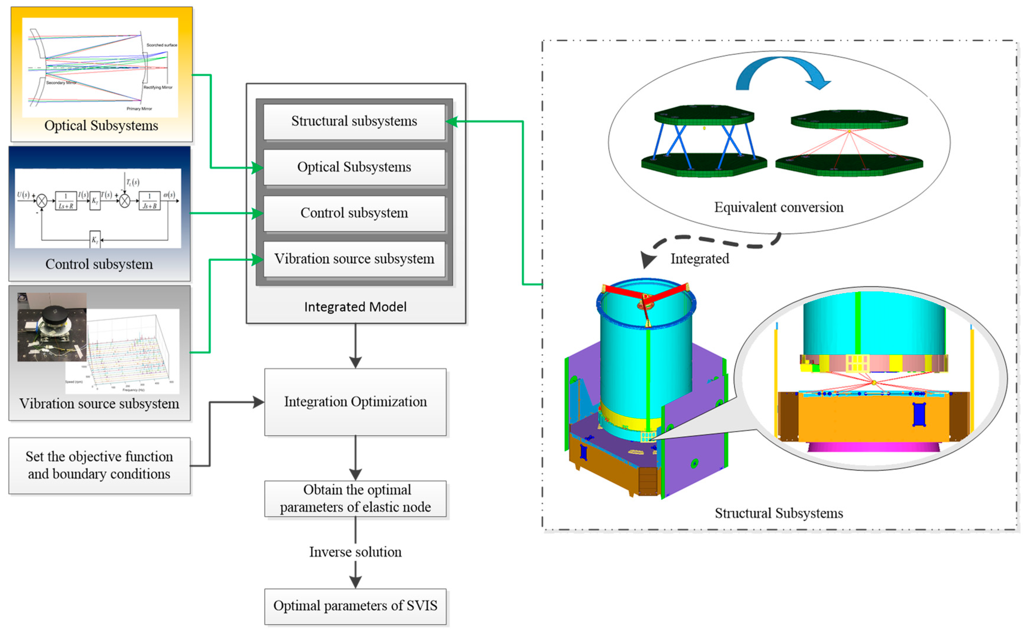
It is frequently necessary to build an integrated model that incorporates numerous subsystems when examining complicated systems. Among them, the dynamic subsystem usually adopts the FEM method as the analysis vehicle. In the previous approach, the SVIS integrated into the FEM models requires a predetermination of the overall structural parameters, which greatly limits the flexibility of the SVIS parameter settings. As a result, although the approach is valid for the forward analysis of the vibration isolation performance under the global integrated model, it is a challenging process to achieve the parametric optimal solution of the SVIS. This is due to the fact that the FEM elements corresponding to the SVIS must be completely constructed before the SVIS can be integrated into the FEM model. During the process, when the structural parameters of the SVIS are modified, the FEM elements of the SVIS inevitably need to be recreated, which makes it a complicated process to reset the SVIS parameters. Thus, it is hard to achieve an automatic optimization of the structural parameters of the SVIS under the global integrated model. By comparison, the stiffness equivalence method proposed in this paper provides a useful strategy. According to the method in this paper, the SVIS is equivalent to a 6-DOF elastic node, as shown in Figure 6, and fast iteration of SVIS parameters can be realized by repeatedly changing the parameters of the elastic node, which eliminates the process of repeated mesh division for the SVIS. Therefore, the parameters related to the elastic node can be adopted directly as the optimization variables for the iterative design of the SVIS, making it possible to achieve the integrated optimization design of the SVIS in complex systems.
Here, we take the vibration isolation design for the optical load of a remote-sensing satellite as an example to instruct the actual application of the theory proposed in this paper. First, according to the theory in Section 2.3, the SVIS can be equated to an elastic node, and the relevant parameters and the stiffness characteristics of the elastic node can be referred to the Section 2.2. The SVIS, in the form of an elastic node, is incorporated into the FEM models of the satellite. Then, the FEM model acts as a dynamic subsystem added to the integrated model, in which the parameters of the elastic node are treated as optimization variables. Next, the iterative optimization is conducted to solve the optimal parameter solution of the elastic node in accordance with the performance indices of the optical load. After that, the solution for the optical parameters of the SVIS can be accomplished according to the theory regarding the parameter inverse solution in Section 2.4 based on the optimal parameters of the elastic node. Through the above procedures, the theoretical parameter design of the SVIS with optimal performance can finally be achieved. The primary flow refers to Figure 7.
3. Simulations and Tests of Stewart Vibration Isolation Platform
In order to verify the rationality of the proposed theory that the SVIS can be equated to an elastic node, a prototype of the Stewart vibration isolation platform (SVIP) is developed. In this section, the FEM simulation and dynamics test of the SVIP prototype are related successively to conduct further research. In general, the modal characteristics and dynamic transmission characteristics of vibration isolation systems are two performances of interest that are often concerned during the vibration isolation design. This leads to a specific analysis and discussion of the results from simulations and testing at two levels: modal characteristics and frequency response characteristics.
3.1. Overview of Stewart Platform Prototype
3.1.1. Introduction to Structure of the SVIP Prototype
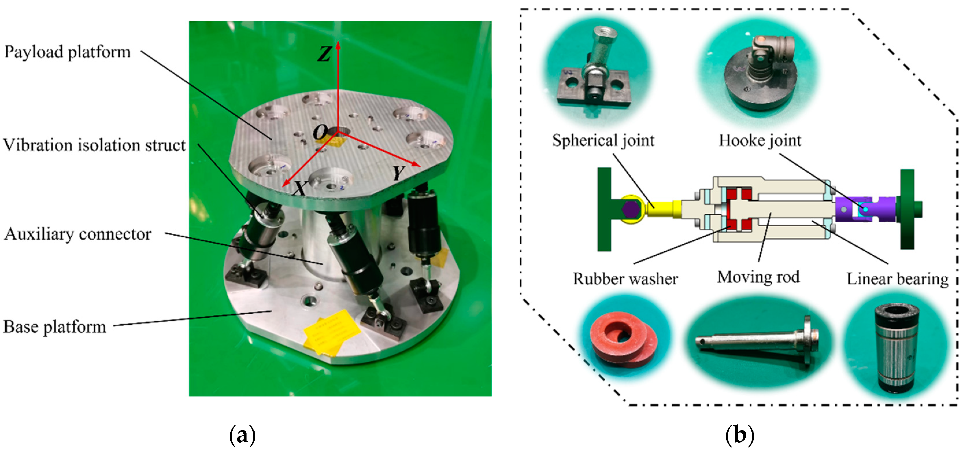
The SVIP developed in this paper adopts UPS configuration, and the main structure of the platform consists of a payload platform, a base platform, and six parallel vibration isolation struts. The vibration isolation struts are connected to the payload and base platforms by Hooke joints and spherical joints, respectively. Figure 8a depicts the SVIP prototype’s precise construction and specification of its coordinate system. It is important to note that the positional accuracy of the joint points within 0.2 mm has been certified by reasonable measurement and calculation. The overall stiffness change to the platform system induced by the structural dimensional mistake does not exceed 2.5%, according to the error analysis, which guarantees the test’s reliability.
The construction diagram of the SVIP’s vibration isolation struts is shown in Figure 8b. The strut is equipped with a pair of silicone rubber washers to provide stiffness and damping for the vibration isolation system. In addition, one linear bearing is installed in each strut to limit the displacement of the moving rod, so that it can only move along the axial direction of the strut. In this way, it ensures that the vibration isolation strut has single degree-of-freedom stiffness and damping characteristics along the axial direction.
3.1.2. Parameter Setting of the SVIP Prototype
In this paper, the primary parameters of the SVIP prototype designed mainly refer to the isolation requirements of a certain optical load. Additionally, the pertinent parameters were approximated throughout the construction of the prototype after taking into account elements such as the actual production and test operation. The final parameters of the dimensions and quality of the SVIP are shown in Table 1:
In order to achieve as much consistency in the stiffness characteristics of the struts as possible, we carried out mechanical tests on multiple groups of rubber washers produced in the same batch. Six groups of rubber washers with the most consistent stiffness and damping properties were ultimately screened out of these following the tests and assembled into the struts. The coefficients obtained through the tests are shown in Table 2:
3.1.3. Theoretical Calculation of the SVIP
In practical applications, the payload platform part fixed to the isolated object usually has much larger mass characteristics compared to the vibration isolation struts, so that the influence of the quality from the struts can be ignored. However, the SVIP developed in this paper is just a basic prototype with no additional payload, and the research mainly focuses on the stiffness-damping characteristics of SVIS. Thus, to ensure the accuracy of the results, the mass characteristics of the struts will be factored in.
The SVIP dynamics formula is provided in Section 2.1. When the struts’ mass is taken into consideration, the general mass matrix in Equation (1) is rewritten as: ; here, and are, respectively, the general mass matrices of the payload platform and the vibration isolation struts in OB-XYZ. Since it is simple to obtain the matrix , only the derivation of is provided here:
where:
Here, denotes the unit vector of the -th strut; denotes the length of the -th strut; is the third-order identity matrix; is the coordinate transformation matrix between the coordinate systems OP-XYZ and OB-XYZ; is the coordinate of the joint point related to the -th strut in OP-XYZ. The remaining parameters refer to Table 1.
When the damping and disturbance force terms in Equation (1) are removed in order to solve for the modes of SVIP, the equation can be used. The first six-order natural frequencies and associated modes of the SVIP can be determined using the solution; the findings are displayed in Table 3:
When analyzing the vibration transmission characteristics of the SVIP, as mentioned in Section 2.1, the base platform is treated as the input end of the disturbance and the payload platform as the output end. The dynamics formula of the SVIP can be described as:
Given that the displacement of the payload platform is , and the displacement of the base platform is , when applying a sinusoidal excitation to the base platform, the displacement of the base platform is , here, .
The Laplace transform on the above Equation (11) yields:
After further derivation, the vibration transfer function can be obtained:
If , the transfer function can be rewritten as: ;
When the base platform only occurs the translational displacement in X direction, there is:
The frequency response curves of the payload platform can be obtained by the transfer function. Similarly, the frequency response curves of other directions can be obtained. Only the three vibration transmission curves corresponding to the X, Y, and Z translational directions are provided in this work to match the testing. The specific results are presented in a comparative format in the subsequent simulations and experimental contents.
3.2. FEM Simulations of SVIP Prototype
3.2.1. FEM Model Setting
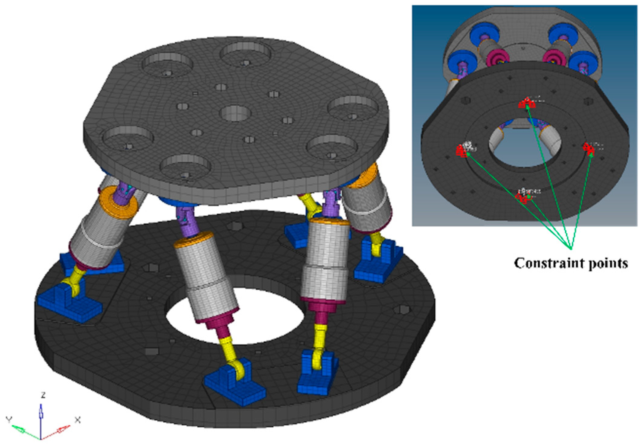
Figure 9 depicts the platform’s FEM model, which contains 73,732 elements and 89,701 nodes in total. The six degrees of freedom of the nodes at the bolt hole beneath the base platform are restricted in the modal analysis. The vibration inputs and accompanying limitations are applied to the nodes at the bolt holes in the frequency response analysis. The input excitation is in the form of acceleration, the frequency range is 10~500 Hz, and the magnitude is 0.1 g. The observation location for the measurement of frequency response results is chosen to be in the middle of the upper surface of the payload platform.
3.2.2. Modal Analysis Results
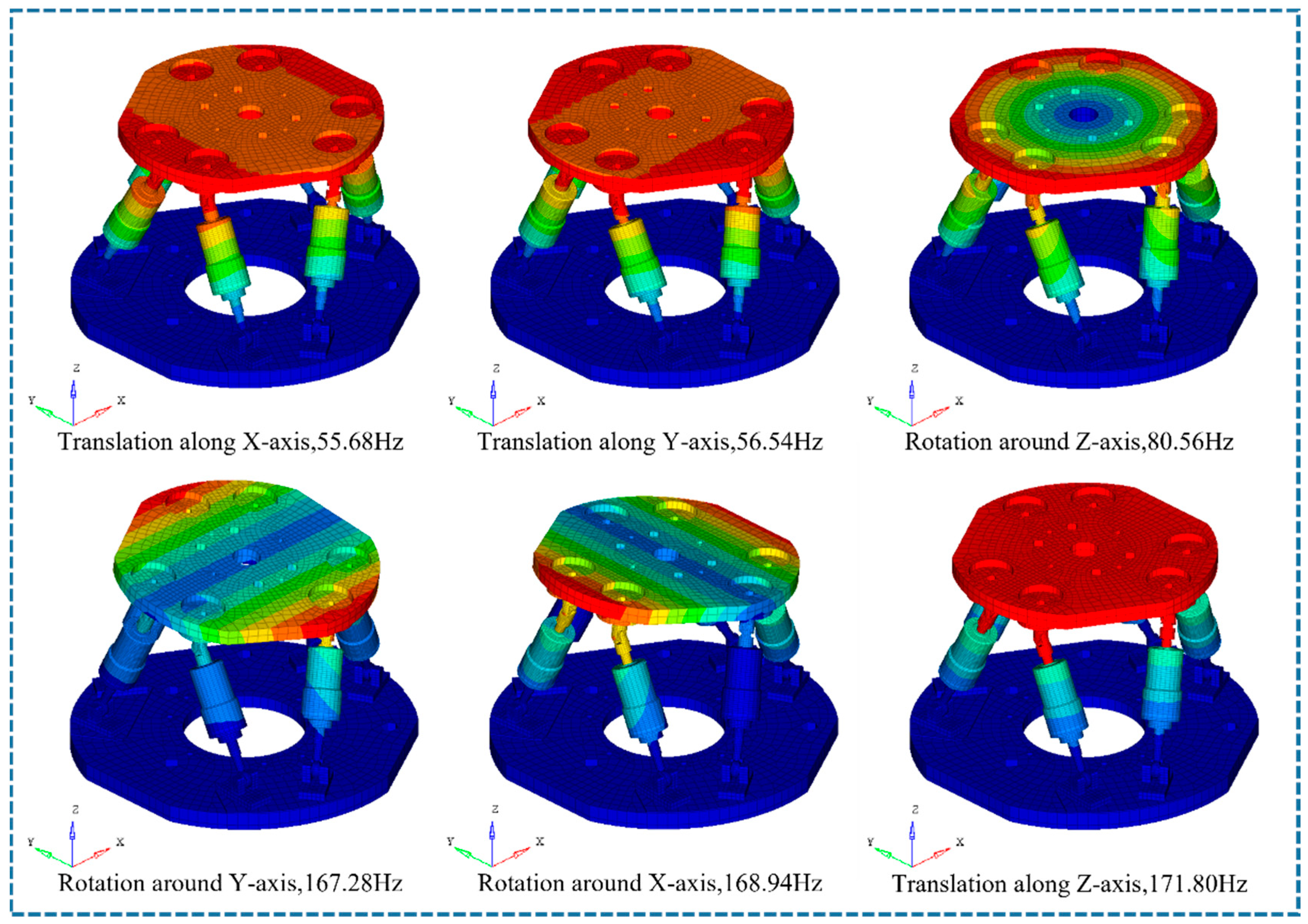
Figure 10 displays the SVIP’s first six modes and related natural frequencies. The first and second modes of the payload platform are shown in the figure to be translational along the X/Y axis, the fourth and fifth modes are rotational along the XY axis, and the third and sixth modes are rotational and translational about the Z axis, respectively. The results of the FEM simulation indicate that the modal properties of the SVIP concur with the theoretical findings. The FEM simulation results suggest that the modal characteristics of the SVIP agree with the theoretical results.
Table 4 displays the matching natural frequencies for each order mode of the SVIP. The table shows that the natural frequency results solved by FEM are virtually identical to those obtained by theoretical calculation. The maximum error does not exceed 1%, which supports the theory proposed.
3.2.3. Frequency Response Analysis Results
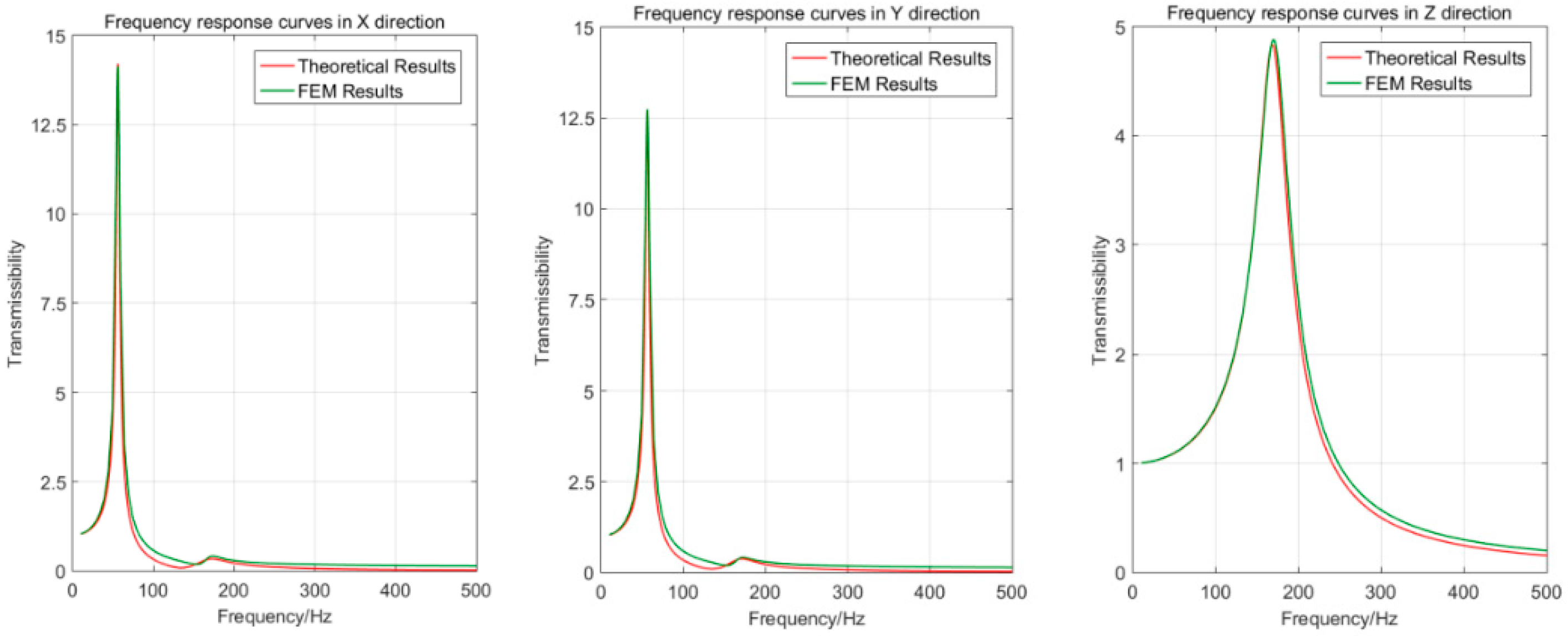
The frequency response curves of the X/Y/Z directions are obtained through the FEM simulation of frequency response analysis for the SVIP, as illustrated in Figure 11. By comparing the results of the frequency response curves between the FEM simulation and the theoretical calculation, it can be found that the FEM results come close to the theoretical results in terms of vibration transmission characteristics, which further confirms the stiffness equivalence method in theory.
The symmetry of the SVIP in the X and Y directions means that the frequency response curves for these two directions are plainly comparable. Furthermore, two resonance peaks can be seen on the frequency response curves in the X direction, and the frequencies of these peaks are exactly the same as the natural frequencies for the payload platform’s translational mode in the X direction and rotational mode around the Y direction. This is consistent with the idea that the SVIP is coupled in the X and Ry directions. The Y direction has the same frequency response curve. On the frequency response curve for the Z direction, there is only one resonance peak, because the mode in that direction is independent and decoupled from other directions. The results of the modal analysis and the results mentioned above match identically.
3.3. Dynamics Tests of SVIP Prototype
3.3.1. Platform Prototype Test Setting
The dynamics experiments were carried out as frequency response vibration tests, allowing for the acquisition of frequency response curves for comparison with the theoretical outcomes. In the tests, the SVIP prototype was successively subjected to the vibration excitation in the X, Y, and Z directions, and the response of the center above the payload platform was recorded. The coordinate system in the tests was defined in accordance with the SVIP’s own coordinate system, as shown in Figure 8a.
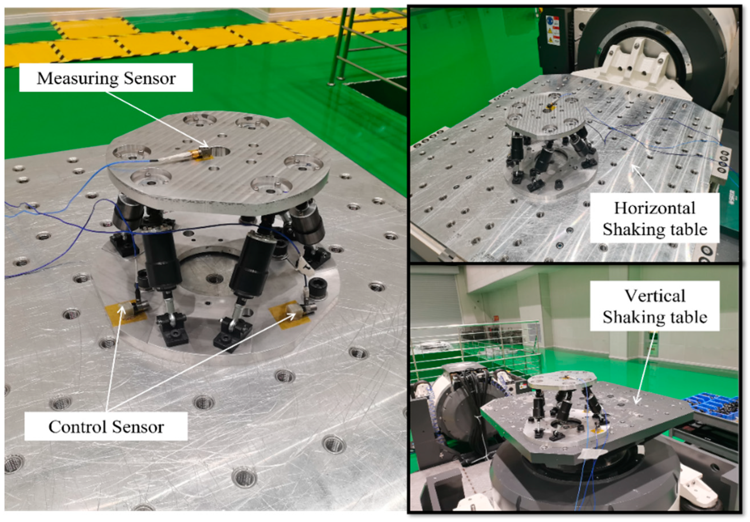
The SVIP prototype was placed on the shaking table during the tests, with the base platform fixed with the table, as shown in Figure 12. The vibration excitation was input to the base platform through the shaking table. The sensors’ placement is shown in the figure below. The sensors No. 1 and No. 2, serving as control sensors, were pasted on the base platform, whereas the sensor No. 3, serving as the measuring sensor, was attached near the center above the payload platform. Throughout the testing, the sensor’s direction was maintained to be parallel to that of the excitation force. The test was conducted sequentially in the directions of X, Y, and Z with the excitation input as a sinusoidal scanning vibration, and the exact excitation parameters are presented in Table 5.
3.3.2. Test Results
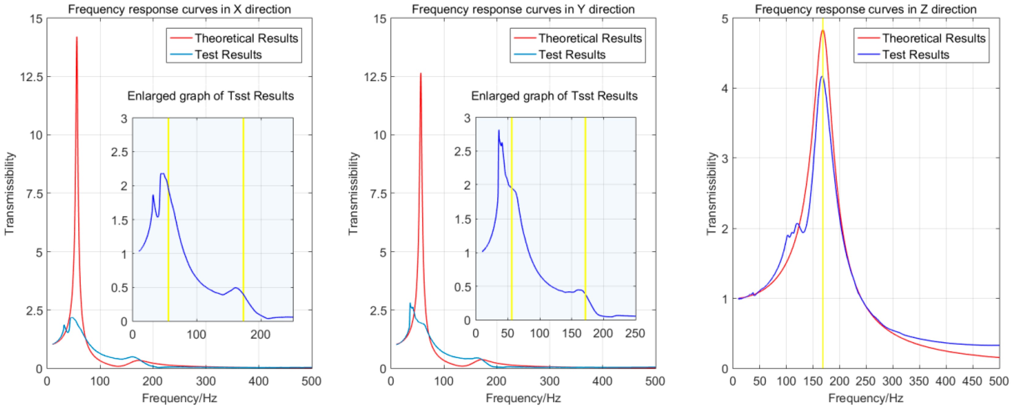
Two sets of responses to the tests were gathered and, in turn, measured by the measuring sensor and the control sensor, respectively. The vibration transmission rate is determined by the ratio of the two set of responses. The frequency response curves were drawn using data from the first 500 Hz band. Figure 13 shows the frequency response curves in the X, Y, and Z directions.
The frequency response curves have two peaks in the X direction, spanning a large and a tiny one, as shown in Figure 12, but just one resonant peak in the Z direction. This conforms to the theory that there exists a coupling of the SVIP about the X-axis and Y-axis as well as decoupling in the Z direction.
The locations of the theoretically calculated resonance peaks are depicted in the figure by the yellow lines. The first and second order maxima in the curves of the X/Y direction exhibit a general shift to the left in comparison to theory. The inaccuracy is only 1.6% for the frequency response curves in the Z direction, which are more closely aligned with the theory. The comparison of the resonant frequencies on the curves derived from the experiments and the theory is shown in Table 6.
Regarding the amplitude, in the X/Y direction, there is a significant decrease in the first-order peak relative to the theoretical results, whereas the second-order peak is close to the theoretical curve. However, the curve of the Z direction is much more satisfactory, meeting the theory well. The curve of the Z-direction, however, is far more satisfactory and relatively fits the idea.
In general, the overall trend of the frequency response curves obtained from the tests agree with the theory, which supports the theory in this paper.
3.3.3. Analysis and Discussion of Test Results
The FEM simulation results are in good agreement with the theory, though there are certain discrepancies in the experimental results compared to the theory and simulations. The author makes the following inferences about this, as follows:
After the Literature Research and Analysis, the apparently unsatisfactory results of the tests are caused by the structural clearances existing in the prototype, according to the literature study and analysis. There are two sources of the clearances in the SVIP prototype, including the rigid joints and the vibration isolation struts. The most noticeable of these, with a value close to 0.1 mm, is the radial clearance between the moving rod and the linear bearing in the strut. The existence of clearances makes the system inevitably display nonlinear behaviors such as collision and friction during the motion process, which consequently affects the dynamic behavior of the system [35].
Through the analysis of the test frequency response curves, it is known that the deviation mainly comes from the results in the horizontal (X/Y) direction. The frequencies corresponding to the peaks of the frequency response curves in X/Y direction have a significant decrease compared with the theoretical results. The curves suggest that the overall trend of the first-order resonance peak is shifted to the left by about 6 Hz, and that of second-order resonance peak is shifted to the left by about 11 Hz. This is caused by the loss of stiffness of the system in the horizontal direction during the dynamics test of the SVIP prototype, which in turn leads to an overall decrease in natural frequency. In the previous clearance models [36,37,38], the equivalent stiffness between the contact surfaces decreases relative to the ideal case, which then results in a loss of overall stiffness in a multi-body system. Different from the horizontal direction, there exists the action of gravity in the vertical (Z) direction. The test frequency response excitation size is only 0.1 g, much lower than gravity, which resulted in the structural clearances being compressed in the Z direction by gravitational force. As a result, the influence of the stiffness loss caused by the structural clearances was suppressed during the vibration isolation test in the Z direction. Therefore, the test results of Z direction can coincide well with the theoretical results. The phenomenon that the clearances reduce the natural frequency of the system are also stated in literature [39,40,41]. Additionally, the author performed calculations at a 12% reduction in the theoretical stiffness of the SVIP prototype, and the result obtained is that the first- and second-order natural frequencies in the X/Y direction of the platform are approximately 52 Hz and 161 Hz. The theoretical results of this case are relatively closer to the test results, which further confirms the validity of the explanation about the loss of stiffness caused by structural clearances.
Regarding the amplitude, on the frequency response curves of the X/Y direction, the second-order peak of the curve has a relative similarity to the theoretical results, whereas the first-order peak decreases significantly compared to the theory. In comparison, the curve of the test in the Z direction is far more satisfactory. As for this phenomenon, it is considered that when the vibration isolation platform remains static, the system clearances are compressed under the influence of gravity, so that the pair of surfaces at the clearances are in a state of contact. When conducting frequency response tests, the platform prototype vibrated under the acceleration excitation, so that the contact force at the clearances could be affected and change. Since the gravity is along the Z axis downward, the contact state of the pair of surfaces at the clearances can remains stable under the acceleration excitation in the Z direction. Comparatively, the contact state is much more sensitive to the excitation in the X/Y direction. When the platform vibrates under the acceleration in the X/Y direction, with the occurrence of resonance leading to a larger acceleration response of the system, the contact state of the contact surface is gradually destroyed, and such an iterative process of ‘separation-collision’ occurs between moving parts at the clearances. Together with the influence of damping by a lubricating substance at the clearances [42,43], it results in the mechanical energy of the lower platform being consumed during the transfer from the lower platform to the upper platform. Eventually, the amplitude of the first-order peak on the X/Y-direction frequency response curve decreases significantly. When second-order resonance occurs, the X/Y acceleration response is much smaller, so the contact state at the clearance can be much more stable and the transfer of mechanical energy is much smoother. On the other hand, during the vibration process of the platform, the movement of the strut is superimposed by two states of oscillation and extension. When the first-order translation mode of the upper platform is excited, the strut motion is dominated by oscillation motion, and when the second-order rotation mode is excited, the strut motion is dominated by extend-retract motion (this has been verified by FEM modal analysis). Thus, the radial clearance between the moving rod and the linear bearing has much less effect on the second-order mode compared to the first-order mode. As a result, the second-order peak amplitude on the frequency response curve is closer to the theory than the first-order peak. Further, the friction caused by the relative motion of the structural parts around the clearance is a secondary reason for the mechanical energy consumption [38,43]. Therefore, the amplitude of the resonance peak of the curves of the Z direction, where the clearances work poorly, is also reduced from the theoretical result. In addition, this is one of the factors that affect the amplitude of the frequency response curves of the X/Y direction.
The mechanism that clearance exerts on the multi-body system is very complex, and its nonlinear behaviors cause certain uncertainties for the stiffness characteristics and the energy transfer of the system. The distribution of the clearances in the SVIP prototype is rather complicated, and the relevant parameters are also hard to measure in practice, so the author can only give a qualitative explanation for the deviations of tests. Since the non-linear effects of clearance on the SVIP are obvious and difficult to control precisely, it should be avoided in the structural design of SVIS for high precision requirements. In the subsequent work, the author will concentrate on the clearance problem to make structural improvements for the SVIP.
4. Conclusions
In this study, an innovative SVIS parameter modeling approach is proposed around the design of multi-dimensional vibration isolation in complex systems. Through the derivation and analysis of the relevant dynamics theory, the SVIS is equated to an elastic node with 6-DOF stiffness-damping characteristics, which can clearly and simply reveal the influence mechanism of parameters on the overall stiffness-damping characteristics in an explicit form. Further, the parameter transformation process of the equivalent model is provided completely. Based on the theory, the parameter characteristics and the usage boundaries of the equivalent SVIS model are systematically analyzed and discussed in this paper. Further, a theory-based parametric design process is presented to introduce the application of a proposed modeling approach with the example of remote-sensing satellite vibration isolation design.
In order to verify the rationality of the equivalent stiffness modeling, the prototype of a SVIP was developed, then the rationality of the stiffness equivalence method of the SVIS was verified from the two aspects of FEM simulations and dynamics tests. The simulation results show that the natural frequencies obtained by the FEM modal analysis and the theoretical results are no more than 1%, and the corresponding modes are consistent with the theory. Further, the frequency response curves obtained from the FEM analysis highly coincide with the theoretical results. The equivalent modeling method proposed in this paper can be strongly demonstrated by the FEM simulation. Regarding the tests, the frequency response curves of the X/Y/Z directions were obtained by conducting frequency response tests on the SVIP prototype. The results show that the frequency corresponding to the resonance peak differs from the theory by 1.7% in the Z direction, and the overall trend of the curve relatively close to the theory. Due to the structural clearances of the platform prototype, the frequency response curves of the X/Y-direction have certain deviations compared with the theory, but the overall trends agree with the theoretical analysis. Despite the somewhat unsatisfactory experimental results, the theory in this paper can still be considered reasonable. It was found that structural clearances can affect the dynamic characteristics unexpectedly through the test results and the error analysis. This problem will be fixed through structural modifications in an upcoming work.
The purpose of this research is to offer a theoretical framework for the parameter design of SVIS applied in complex systems.
Author Contributions
Conceptualization, T.Z. and X.G.; methodology, T.Z.; software, T.Z.; validation, T.Z.; formal analysis, T.Z.; investigation, T.Z.; resources, T.Z.; data curation, T.Z.; writing—original draft preparation, T.Z.; writing—review and editing, T.Z., X.G. and Y.Y.; visualization, T.Z.; supervision, L.Z.; project administration, L.Z.; funding acquisition, L.Z. All authors have read and agreed to the published version of the manuscript.
Funding
This research was funded by Scientific and Technological Developing project of Ji Lin Province, No. 20210509052RQ.
Institutional Review Board Statement
Not applicable.
Informed Consent Statement
Not applicable.
Data Availability Statement
Not applicable.
Acknowledgments
The authors would like to acknowledge the contribution of all authors of this paper, the technical support from Chang Guang Satellite Technology Co., Ltd., and the funding from the Scientific and Technological Developing project of Ji Lin Province. We also thank the editors and reviewers for your time and effort in reviewing this paper.
Conflicts of Interest
The authors declare no conflict of interest.
References
- Furqan, M.; Suhaib, M.; Ahmad, N. Studies on Stewart platform manipulator: A review. J. Mech. Sci. Technol. 2017, 31, 4459–4470. [Google Scholar] [CrossRef]
- Gough, V.E. Contribution to discussion of papers on research in automobile stability, control and tyre performance. Proc. Auto Div. Inst. Mech. Eng. 1957, 171, 392–395. [Google Scholar]
- Bi, F.; Ma, T.; Wang, X.; Yang, X.; Lv, Z. Research on vibration control of seating system platform based on the cubic stewart parallel mechanism. IEEE Access 2019, 7, 155637–155649. [Google Scholar] [CrossRef]
- Duan, X.; Qiu, Y.; Mi, J.; Bao, H. On the mechatronic servo bandwidth of a stewart platform for active vibration isolating in a super antenna. Robot. Comput.-Integr. Manuf. 2016, 40, 66–77. [Google Scholar] [CrossRef]
- Duan, X.; Mi, J.; Zhao, Z. Vibration Isolation and Trajectory Following Control of a Cable Suspended Stewart Platform. Machines 2016, 4, 20. [Google Scholar] [CrossRef] [Green Version]
- He, Z.; Feng, X.; Zhu, Y.; Yu, Z.; Li, Z.; Zhang, Y.; Wang, Y.; Wang, P.; Zhao, L. Progress of Stewart Vibration Platform in Aerospace Micro–Vibration Control. Aerospace 2022, 9, 324. [Google Scholar] [CrossRef]
- Wang, C.; Xie, X.; Chen, Y.; Zhang, Z. Investigation on active vibration isolation of a Stewart platform with piezoelectric actuators. J. Sound Vib. 2016, 383, 1–19. [Google Scholar] [CrossRef]
- Zheng, Y.; Li, Q.; Yan, B.; Luo, Y.; Zhang, X. A Stewart isolator with high-static-low-dynamic stiffness struts based on negative stiffness magnetic springs. J. Sound Vib. 2018, 422, 390–408. [Google Scholar] [CrossRef]
- Pu, H.; Yuan, S.; Peng, Y.; Meng, K.; Zhao, J.; Xie, R.; Huang, Y.; Sun, Y.; Yang, Y.; Xie, S.; et al. Multi-layer electromagnetic spring with tunable negative stiffness for semi-active vibration isolation. Mech. Syst. Signal Processing 2019, 121, 942–960. [Google Scholar] [CrossRef]
- Ma, G.; Liu, Y.; Sun, Y.; Ma, J. Active vibration isolation for Stewart platform using backstepping and NFTSM control. In 2016 IEEE Chinese Guidance, Navigation and Control Conference (CGNCC); IEEE: Piscataway, NJ, USA, 2016; pp. 1264–1269. [Google Scholar]
- Yang, X.L.; Wu, H.T.; Chen, B.; Kang, S.; Cheng, S. Dynamic modeling and decoupled control of a flexible Stewart platform for vibration isolation. J. Sound Vib. 2019, 439, 398–412. [Google Scholar] [CrossRef]
- Chi, W.; Ma, H.; Wang, C.; Zhao, T. Research on Control of Stewart Platform Integrating Small Attitude Maneuver and Vibration Isolation for High-Precision Payloads on Spacecraft. Aerospace 2021, 8, 333. [Google Scholar] [CrossRef]
- Liu, C.; Jing, X.; Daley, S.; Li, F. Recent advances in micro-vibration isolation. Mech. Syst. Signal Processing 2015, 56, 55–80. [Google Scholar] [CrossRef]
- Li, L.; Wang, L.; Yuan, L.; Zheng, R.; Wu, Y.; Sui, J.; Zhong, J. Micro-vibration suppression methods and key technologies for high-precision space optical instruments. Acta Astronaut. 2021, 180, 417–428. [Google Scholar] [CrossRef]
- Li, L.; Tan, L.; Kong, L.; Yang, H.; Wang, D. Flywheel micro-vibration characters of a high resolution optical satellite. J. Vibroeng. 2017, 19, 3981–3993. [Google Scholar] [CrossRef] [Green Version]
- Geng, Z.; Haynes, L.S.; Lee, J.D.; Carroll, R.L. On the dynamic model and kinematic analysis of a class of Stewart platforms. Robot. Auton. Syst. 1992, 9, 237–254. [Google Scholar] [CrossRef]
- Liu, K.; Lewis, F.; Lebret, G.; Taylor, D. The singularities and dynamics of a Stewart platform manipulator. J. Intell. Robot. Syst. 1993, 8, 287–308. [Google Scholar] [CrossRef]
- Abdellatif, H.; Heimann, B. Computational efficient inverse dynamics of 6-DOF fully parallel manipulators by using the Lagrangian formalism. Mech. Mach. Theory 2009, 44, 192–207. [Google Scholar] [CrossRef]
- Dasgupta, B.; Mruthyunjaya, T.S. A Newton-Euler formulation for the inverse dynamics of the Stewart platform manipulator. Mech. Mach. Theory 1998, 33, 1135–1152. [Google Scholar] [CrossRef]
- Cheng, Y.; Ren, G.; Dai, S.L. The multi-body system modelling of the Gough–Stewart platform for vibration control. J. Sound Vib. 2004, 271, 599–614. [Google Scholar] [CrossRef]
- Pedrammehr, S.; Mahboubkhah, M.; Khani, N. Improved dynamic equations for the generally configured Stewart platform manipulator. J. Mech. Sci. Technol. 2012, 26, 711–721. [Google Scholar] [CrossRef]
- Jiang, H.Z.; He, J.F.; Tong, Z.Z. Characteristics analysis of joint space inverse mass matrix for the optimal design of a 6-DOF parallel manipulator. Mech. Mach. Theory 2010, 45, 722–739. [Google Scholar] [CrossRef]
- Afzali-Far, B.; Lidström, P.; Nilsson, K. Parametric damped vibrations of Gough–Stewart platforms for symmetric configurations. Mech. Mach. Theory 2014, 80, 52–69. [Google Scholar] [CrossRef]
- Chen, J.; Lan, F. Instantaneous stiffness analysis and simulation for hexapod machines. Simul. Model. Pract. Theory 2008, 16, 419–428. [Google Scholar] [CrossRef]
- Yao, J.; Hou, Y.; Wang, H.; Zhao, Y. Isotropic design of Stewart platform-based force sensor. In International Conference on Intelligent Robotics and Applications; Springer: Berlin/Heidelberg, Germany, 2008; pp. 723–732. [Google Scholar]
- Bandyopadhyay, S.; Ghosal, A. An algebraic formulation of static isotropy and design of statically isotropic 6–6 Stewart platform manipulators. Mech. Mach. Theory 2009, 44, 1360–1370. [Google Scholar] [CrossRef] [Green Version]
- Kumar, S.G.; Nagarajan, T.; Srinivasa, Y.G. Characterization of reconfigurable Stewart platform for contour generation. Robot. Comput.-Integr. Manuf. 2009, 25, 721–731. [Google Scholar] [CrossRef]
- Yang, J.; Xu, Z.; Wu, Q.; Wang, Z.; Li, H.; He, S. Design of a Vibration isolator for the Space Telescope. J. Guid. Control Dyn. 2015, 38, 2441–2448. [Google Scholar] [CrossRef]
- Shyam, R.B.A.; Ahmad, N.; Ranganath, R.; Ghosal, A. Design of a dynamically isotropic Stewart-Gough platform for passive micro vibration isolation in spacecraft using optimization. J. Spacecr. Technol. 2019, 30, 1–8. [Google Scholar]
- Baig, R.U.; Pugazhenthi, S. Neural Network Optimization of Design Parameters of Stewart Platform for Effective Active Vibration Isolation. J. Eng. Appl. Sci. 2014, 9, 78–84. [Google Scholar]
- Li, Y.; Yang, X.; Wu, H.; Chen, B. Optimal design of a six-axis vibration isolator via Stewart platform by using homogeneous Jacobian matrix formulation based on dual quaternions. J. Mech. Sci. Technol. 2018, 32, 11–19. [Google Scholar] [CrossRef]
- Singh, Y.P.; Ahmad, N.; Ghosal, A. Design of Dynamically Isotropic Modified Gough-Stewart Platform Using a Geometry-Based Approach. In IFToMM Asian Conference on Mechanism and Machine Science; Springer: Cham, Germany, 2021; pp. 258–268. [Google Scholar]
- Singh, Y.P.; Ahmad, N.; Ghosal, A. Design of dynamically isotropic two radii Gough-Stewart platforms with arbitrary number of struts. In 2021 9th RSI International Conference on Robotics and Mechatronics (ICRoM); IEEE: Piscataway, NJ, USA, 2021; pp. 66–71. [Google Scholar]
- Jiang, H.; He, J.; Tong, Z.; Wang, W. Dynamic isotropic design for modified Gough–Stewart platforms lying on a pair of circular hyperboloids. Mech. Mach. Theory 2011, 46, 1301–1315. [Google Scholar] [CrossRef]
- Tian, Q.; Flores, P.; Lankarani, H.M. A comprehensive survey of the analytical, numerical and experimental methodologies for dynamics of multibody mechanical systems with clearance or imperfect joints. Mech. Mach. Theory 2018, 122, 1–57. [Google Scholar] [CrossRef]
- Hunt, K.H.; Crossley, F.R.E. Coefficient of restitution interpreted as damping in vibroimpact. J. Appl. Mech. 1975, 42, 440–445. [Google Scholar] [CrossRef]
- Lee, T.W.; Wang, A.C. On the dynamics of intermittent-motion mechanisms. Part 1: Dynamic model and response. J. Mech. Des. 1983, 105, 534–540. [Google Scholar] [CrossRef]
- Gonthier, Y.; McPhee, J.; Lange, C.; Piedboeuf, J.C. A regularized contact model with asymmetric damping and dwell-time dependent friction. Multibody Syst. Dyn. 2004, 11, 209–233. [Google Scholar] [CrossRef]
- Moon, F.C.; Li, G.X. Experimental study of chaotic vibrations in a pin-jointed space truss structure. Aiaa J. 2012, 28, 915–921. [Google Scholar] [CrossRef]
- Shiau, T.N.; Tsai, Y.J.; Tsai, M.S. Nonlinear dynamic analysis of a parallel mechanism with consideration of joint effects. Mech. Mach. Theory 2008, 43, 491–505. [Google Scholar] [CrossRef]
- Salahshoor, E.; Ebrahimi, S.; Maasoomi, M. Nonlinear vibration analysis of mechanical systems with multiple joint clearances using the method of multiple scales. Mech. Mach. Theory 2016, 105, 495–509. [Google Scholar] [CrossRef]
- Seifried, R.; Schiehlen, W.; Eberhard, P. Numerical and experimental evaluation of the coefficient of restitution for repeated impacts. Int. J. Impact Eng. 2005, 32, 508–524. [Google Scholar] [CrossRef]
- Muvengei, O.; Kihiu, J.; Ikua, B. Dynamic analysis of planar multi-body systems with LuGre friction at differently located revolute clearance joints. Multibody Syst. Dyn. 2012, 28, 369–393. [Google Scholar] [CrossRef]
Figure 1.
Schematic diagram of Stewart Platform.

Figure 2.
Vibration isolation principle of Stewart platform.

Figure 3.
Diagram of Gough–Stewart configuration lying on the circle hyperboloid of one sheet: (a) schematic of configuration transformation; (b) diagram of parameters.
Figure 3.
Diagram of Gough–Stewart configuration lying on the circle hyperboloid of one sheet: (a) schematic of configuration transformation; (b) diagram of parameters.

Figure 4.
Schematic of equivalent conversion SVIS.

Figure 5.
Diagram of parameter decomposition.

Figure 6.
Schematic diagram of SVIS equivalent to elastic nodes in FEM.

Figure 7.
Integrated optimization design process of SVIS.

Figure 8.
Diagram of SVIP prototype: (a) overview of SVIP; (b) structure of the strut.

Figure 9.
FEM model of the SVIP.

Figure 10.
Modal analysis results of the SVIP.

Figure 11.
Frequency response curves obtained from FEM simulation and theoretical calculation.

Figure 12.
Frequency response tests of the SVIP prototype.

Figure 13.
Frequency response curves obtained from theoretical calculation and tests.


Table 1.
Main parameters of the SVIP.
| Parameter | Numerical Value |
|---|---|
| Radius of joint-point circle of payload platform RP | 100 mm |
| Radius of joint-point circle of base platform RB | 140 mm |
| Distribution angle of joint point of payload platform α | 40° |
| Distribution angle of joint point of base platform β | 30° |
| Height difference between joint-point circles of the platforms H | 124 mm |
| Position of the centroid of the load in OB-XYZ | [0, 0, 170.5] mm |
| Distance from centroid of upper part of strut to payload joint point lsp | 45.2 mm |
| Distance from centroid of lower part of strut to base joint point lsb | 76.3 mm |
| Mass of payload platform m | 3.00 kg |
| Mass of the upper part of the strut msp | 0.067 kg |
| Mass of lower part of strut msb | 0.50 kg |
| Inertia tensor of payload relative to the centroid I | [13,294, 13,300, 26,120] kg·mm2 |
| Inertia tensor of the upper part of the strut relative to the centroid Isp | [46, 46, 2] kg·mm2 |
| Inertia tensor of the lower part of the strut relative to the centroid Isb | [371, 371, 92] kg·mm2 |
Table 2.
Stiffness and damping coefficients of the struts.
| Strut 1 | Strut 2 | Strut 3 | Strut 4 | Strut 5 | Strut 6 | |
|---|---|---|---|---|---|---|
| (N/m) | 831,480 | 787,330 | 799,530 | 840,470 | 785,060 | 793,980 |
| (N/m·s−1) | 214.8 | 160.1 | 143.9 | 199.8 | 163.7 | 156.8 |
Table 3.
Natural frequencies and corresponding modes of the SVIP.
| Natural Frequency | Modal Eigenvector | |
|---|---|---|
| Order 1 | 53.79 | [1.000 0 0 0 −1.940 0] T |
| Order 2 | 54.03 | [0 1.000 0 1.887 0 0] T |
| Order 3 | 77.23 | [0 0 0 0 0 1.000] T |
| Order 6 | 161.86 | [0 −0.038 0 1.000 0 0] T |
| Order 5 | 162.56 | [0.038 0 0 0 1.000 0] T |
| Order 6 | 163.87 | [0 0 1.000 0 0 0] T |
Table 4.
Natural frequencies obtained from theoretical calculation and FEM simulation.
| Mode Form | Theory/Hz | FEM/Hz | Error/% |
|---|---|---|---|
| Translational mode in X direction | 55.94 | 55.68 | −0.46 |
| Translational mode in Y direction | 56.19 | 56.54 | 0.62 |
| Translational mode in Z direction | 170.44 | 171.80 | 0.80 |
| Rotational mode around X direction | 168.34 | 167.28 | −0.63 |
| Rotational mode around Y direction | 169.07 | 168.94 | −0.08 |
| Rotational mode around Z direction | 80.33 | 80.56 | 0.29 |
Table 5.
Test conditions of frequency response excitation.
| Direction | Frequency Range | Vibration Amplitude | Scan Rate |
|---|---|---|---|
| X | 10~800 Hz | 0.1 g | 4 oct/min |
| Y | 10~800 Hz | 0.1 g | 4 oct/min |
| Z | 10~800 Hz | 0.1 g | 4 oct/min |
Table 6.
Resonant frequency of the curves obtained by theory and tests.
| Resonance Form | Theory/Hz | Test/Hz (Approx.) | Deviation/Hz (Approx.) |
|---|---|---|---|
| First order of X direction | 55.9 | 50 | 6 |
| Second order of X direction | 172.6 | 160 | 12 |
| First order of Y direction | 56.2 | 50 | 6 |
| Second order of Y direction | 171.4 | 161 | 10 |
| First order of Z direction | 168.7 | 166 | 2 |
Publisher’s Note: MDPI stays neutral with regard to jurisdictional claims in published maps and institutional affiliations. |
© 2022 by the authors. Licensee MDPI, Basel, Switzerland. This article is an open access article distributed under the terms and conditions of the Creative Commons Attribution (CC BY) license (https://creativecommons.org/licenses/by/4.0/).
Share and Cite
MDPI and ACS Style
Zhang, T.; Gong, X.; Zhang, L.; Yu, Y. A New Modeling Approach for Parameter Design of Stewart Vibration Isolation System Integrated into Complex Systems. Machines 2022, 10, 1005. https://doi.org/10.3390/machines10111005
AMA Style
Zhang T, Gong X, Zhang L, Yu Y. A New Modeling Approach for Parameter Design of Stewart Vibration Isolation System Integrated into Complex Systems. Machines. 2022; 10(11):1005. https://doi.org/10.3390/machines10111005
Chicago/Turabian StyleZhang, Tianqing, Xiaoxue Gong, Lei Zhang, and Yang Yu. 2022. "A New Modeling Approach for Parameter Design of Stewart Vibration Isolation System Integrated into Complex Systems" Machines 10, no. 11: 1005. https://doi.org/10.3390/machines10111005
Note that from the first issue of 2016, this journal uses article numbers instead of page numbers. See further details here.