


Grinding Performance of Laser Cladding WC/Fe Coatings by Different Adding Methods of WC Particles

College of Mechanical Engineering and Automation, Huaqiao University, Xiamen 361021, China
*
Author to whom correspondence should be addressed.
Machines 2022, 10(10), 910; https://doi.org/10.3390/machines10100910
Submission received: 5 September 2022
/
Revised: 29 September 2022
/
Accepted: 30 September 2022
/
Published: 8 October 2022
(This article belongs to the Special Issue High Precision Abrasive Machining: Machines, Processes and Systems)
Abstract
:Laser cladding coatings generally need a follow-up grinding process to acquire the desired dimensional accuracy and surface roughness. In this paper, grinding experimental studies were set up to investigate the grinding performance of iron-based matrix composite coatings (WC/Fe with in situ and ex situ WC particles), using two types of grinding wheels. The influence of grinding parameters such as the cut depth, wheel speed and type of grinding wheel on grinding forces, force ratio, specific energy, surface roughness and the surface appearance of the two coatings was studied. The forming mechanism of the subsurface damages on the two ground coatings was discussed. Experimental results revealed that there were obvious differences between the two coatings in grinding forces, surface roughness and morphology, especially in the subsurface damages. These were attributed to their difference in size and the distribution of the WC particles, as well as their different mechanical properties.
1. Introduction
Laser cladding, one of the modern coating techniques which can strengthen and repair the surface of materials well, has extensive application prospects [1,2,3,4]. Of all the materials used for laser cladding, ceramic particle-reinforced metal matrix composite coatings (PRMMCCs) possess many desirable properties, such as high heat resistance, good corrosion resistance and wear resistance, because they have a high melting point, high hardness and good chemical stability. Thus, it is easy to produce a coating with particular new properties, and the surface properties of machine parts made of a wide variety of materials can be modified [5,6,7]. Unfortunately, the surface of the coated components is usually rough and its dimensional accuracy is poor. It needs to be machined to obtain the desired dimensional accuracy and surface roughness. However, it is difficult to machine metal matrix composite coatings with ceramic particles because the properties of the ceramic particles and the base metal are quite different. Therefore, to achieve the desired surface finish and dimensional accuracy, grinding is the most appropriate method for finishing the coatings.
Many studies have been carried out to investigate the effects of processing parameters on the microstructures, mechanical properties, crack initiation and propagation behavior of laser cladding PRMMCCs [8,9,10,11]. However, for grinding coatings, most of the research has focused on the sprayed ceramic coatings [12,13,14,15,16]. Characteristics such as grinding forces, surface integrity, surface roughness, the wear on the wheel, etc., have been investigated in grinding sprayed coatings. Liu et al. conducted a grinding experiment on thermally sprayed nanostructured coatings (n-WC/12Co and n-Al2O3/13TiO2), using diamond grinding wheels under different grinding parameters. It was observed that the normal grinding force increased when the wheel had a larger grit size and the bond was harder. Both plastic flow and brittle fracture occurred in grinding these coatings. For the n-Al2O3/13TiO2 coatings, there was an optimum cut depth to obtain minimum surface roughness [12]. Kar et al. used single-layer electroplated diamond wheels to study the grinding performance of different plasma sprayed oxide ceramics. They revealed that at a low grinding speed, the removal of material was mainly achieved by microbrittle fracture [13]. During precision grinding of these coatings, the density of subsurface damages and wheel wear increased. Huang and Liu reported that during high-speed grinding of sintered ceramics, their surface finish could be improved, the grinding ratio increased and the subsurface damages reduced [17]. Kar et al. reported that in high-speed grinding of ceramic oxide coatings, grinding forces reduced obviously when the wheel speed increased. Much less damage and much lower surface residual stress were obtained [18]. Rausch et al. reported that using a ceramic binder and resin binder diamond grinding wheel could obtain a better surface quality than using a metal-based and electroplated diamond grinding wheel, in grinding two different thermally sprayed coatings. A smaller grinding force but a greater surface roughness was obtained by using a diamond wheel than by using a cBN wheel [19].
As for grinding laser cladding coatings, very few reports have been published so far. Lin et al. used an electroplated diamond wheel to grind an Fe–Mn–C alloy laser cladding coating by electrolytic grinding and a mechanical grinding method. The ground surface roughness of the coating met the actual working requirements [20]. In the authors’ previous research on the grinding performance of laser cladding Cr3C2/Ni composite coatings, it was found that cracks formed in the coating when the mass fraction of Cr3C2 in the coating was higher than 20%.Higher surface roughness (Ra) of the ground coating was obtained when the size of the Cr3C2 particles was larger [21].
There are two types (in situ and ex situ reinforced particles) of PRMMCCs, according to the adding methods of reinforcement. In situ PRMMCCs are found to have superior mechanical properties and their cracking susceptibility can be reduced [22,23]. Iron-based matrix reinforced with tungsten carbide (WC/Fe) composite coating has a wide practical application value because of its peculiar combination of high wear resistance and relatively low cost. Many researchers have focused on the laser cladding process, microstructure and mechanical properties of WC/Fe coatings [23,24,25,26,27]. The results reveal that the WC particle formed in situ has a much smaller size and distributes more uniformly. As a result, the mechanical properties of the WC/Fe coating are improved. In contrast, ex situ WC/Fe coatings crack easily. Coatings with a higher hardness generally have an increased cracking sensitivity, particularly in coatings which have a high content of WC particles [28,29].
Usually, the grinding performance of a workpiece depends on its microstructures and mechanical properties. Moreover, the constituents of the composite coating should be considered in selecting the wheel type and the grinding parameters [30]. Based on the above literature, it is known that the investigation of the grinding performance of laser cladding coatings is quite limited. Additionally, the difference of the grinding performance characteristics between the composite coatings fabricated by two different methods has not been well studied. In order to provide a theoretical basis for the grinding process for composite coatings by different methods of adding reinforcement, comparison of the microstructures and mechanical properties, as well as grinding performance, under different grinding conditions between in situ and ex situ composite coatings is essential. Thus, in this paper, crack-free ex situ WC/Fe composite coatings with 10% WC (weight percentage) and in situ WC/Fe composite coatings were laser cladded for the grinding performance study. Two types of wheels, made of an ordinary abrasive and a superabrasive, were used to perform the grinding tests.
2. Materials and Methods
Two kinds of WC/Fe composite coatings were laser cladded on steel substrates with 0.45% C (AISI 1045) and dimensions of 50 × 50 × 10 mm3. Each substrate was abraded with an abrader to remove the rust. Then, it was smoothed with a WA120 grinding wheel and cleaned with ethanol before laser cladding. Commercial powders of Fe314 and Rockit701 were used to fabricate the coatings. Detailed compositions of the powders are presented in Table 1 and Table 2. The powders of Fe314 and WC (10% weight percentage, 38 μmin size) were mixed well. The thickness of the preplaced coating was set to be 0.8 mm. AXL-600AW YAG laser equipment was used. Based on our preliminary studies [21,27], several groups of parameters were explored. Finally, the laser parameters were selected to laser clad the crack-free WC/Fe coating specimens for the mechanical properties and grinding performance studies. For ex situ WC/Fe coating, an electric current of 120 A and a beam scanning speed of 3 mm/s were used. For the in situ WC/Fe coating, an electric current of 130 A and a beam scanning speed of 6 mm/s were used. In addition, for both coatings, a fluency of 30 Hz, pulse width of 3 ms, laser beam diameter of 1.5 mm, distance between tracks of 1 mm, with an overlap ratio of approximately 50%, were used.
Microhardness measurement was accomplished in a microhardness tester, under a load of 1.96 N and a retention time of 10 s. The transverse rupture strength (TRS) of the coating specimen was gained by the three-point bending test method. A WD-300K universal testing machine was used. The microstructure was examined by SEM.
Grinding performance studies were carried out on a precision grinder (M250). The samples’ size was 15 × 10 × 10 mm3. Two types of grinding wheels made of alumina abrasive (referred to as WA120) and cubic boron nitride (referred to as 120B-cBN) were used under different grinding conditions. The specifications of the grinding wheels and the experimental parameters are listed in Table 3 and Table 4. Because the removal allowance on the laser coating surface was large, the grinding parameters were set with the expectation to quickly remove the machining allowance without producing serious processing defects. A single-point diamond dresser was used to true and dress the WA120 wheel. An SiC wheel was initially used to true the cBN wheel, and then, a stone with SiC abrasives was used. Both wheels were dressed before and after each experiment during the investigations.
The tangential and normal grinding forces were measured online using a Kistler 9257BA dynamometer. The results of the measured grinding forces were averages of several repetitive grinding tests. The surface roughness (Ra) of the ground coatings was measured by a surface profile meter (Mahr XR20) along the parallel and perpendicular direction to the grinding direction, five times, respectively. The value of Ra was the average of these measurements. the surface morphology of the ground coatings was examined by SEM.
3. Results and Discussion
In order to study the influence of the adding methods of reinforcement on the grinding performance of composite coatings, the microstructures and mechanical properties of in situ and ex situ WC/Fe composite coatings were studied. The comparative grinding performance was studied according to the grinding force, force ratio, specific energy, surface roughness and subsurface damages.
3.1. Microstructures and Mechanical Properties
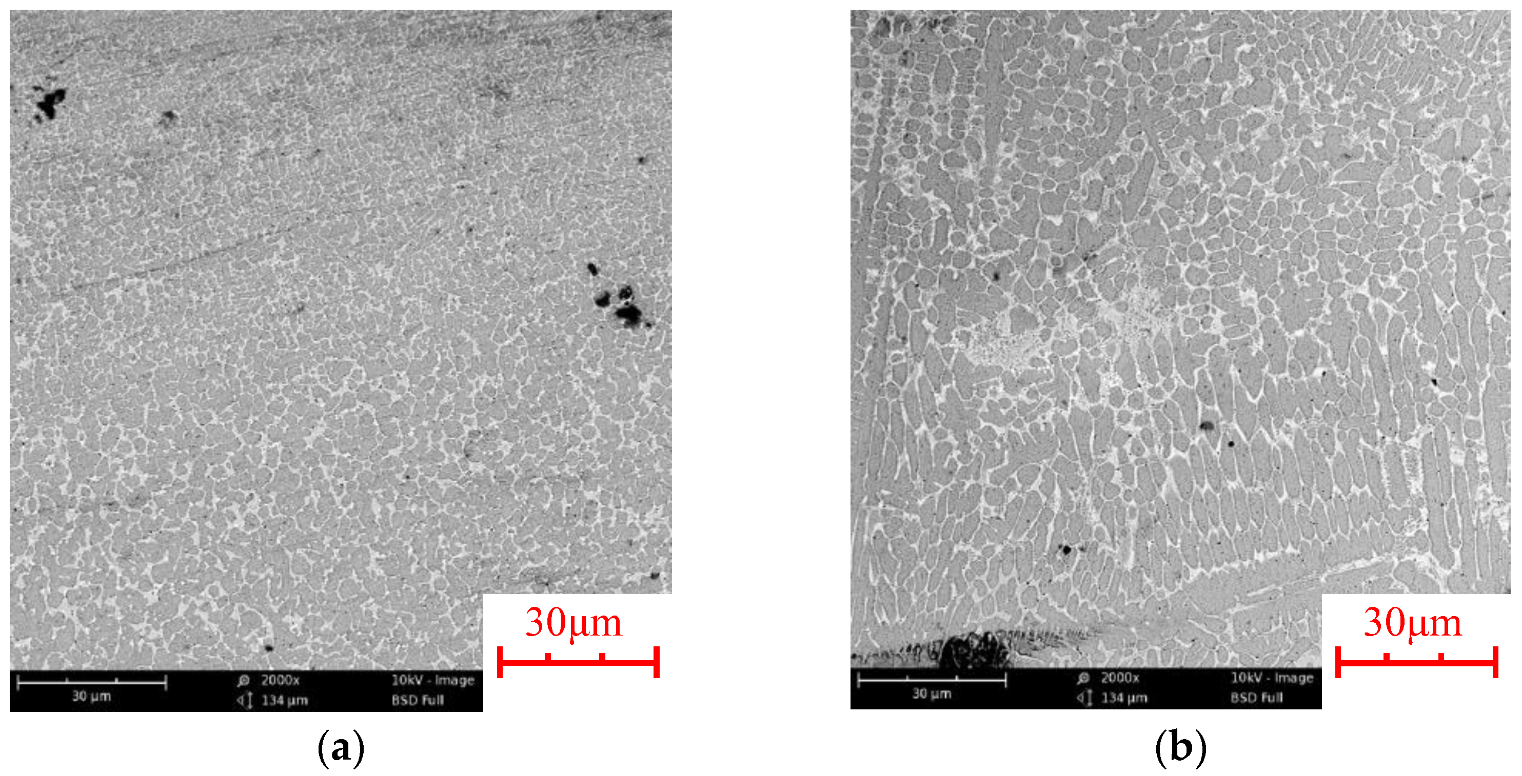
Figure 1a,b are the microstructures of in situ and ex-situ WC/Fe coatings, respectively. It can be seen that the microstructure of the WC/Fe (in situ) coating is much finer and more uniform than that of the WC/Fe (ex situ) coating.
Table 5 shows the microhardness and TRS of in situ and ex situ WC/Fe coatings. From Table 5, one can see that the microhardness of the WC/Fe (in situ) coating is almost twice that of the WC/Fe (ex situ) coating, while the TRS of the former is only slightly smaller than that of the latter. Fine particles may act as the hard phase, which improves the microhardness of the composite coating [22,23].
3.2. Grinding Forces
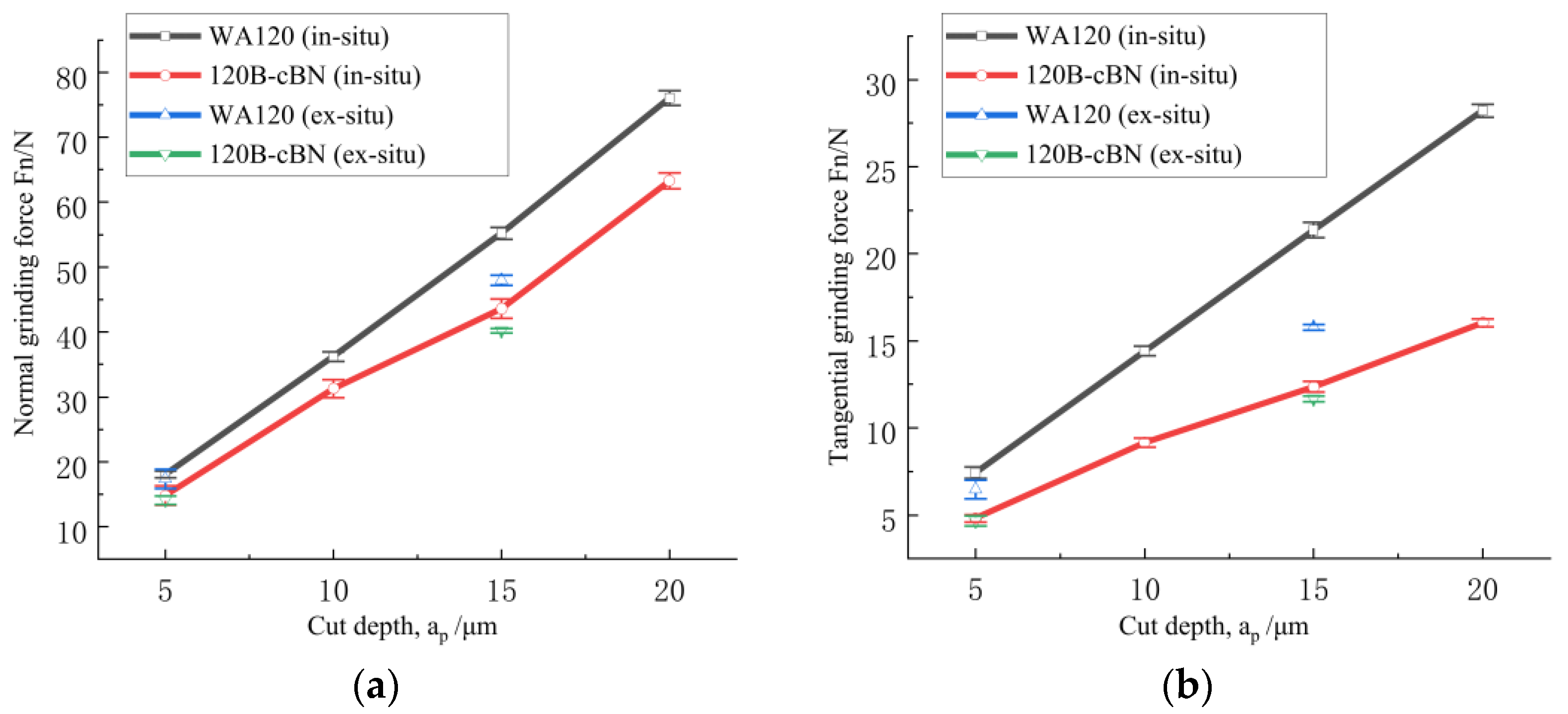
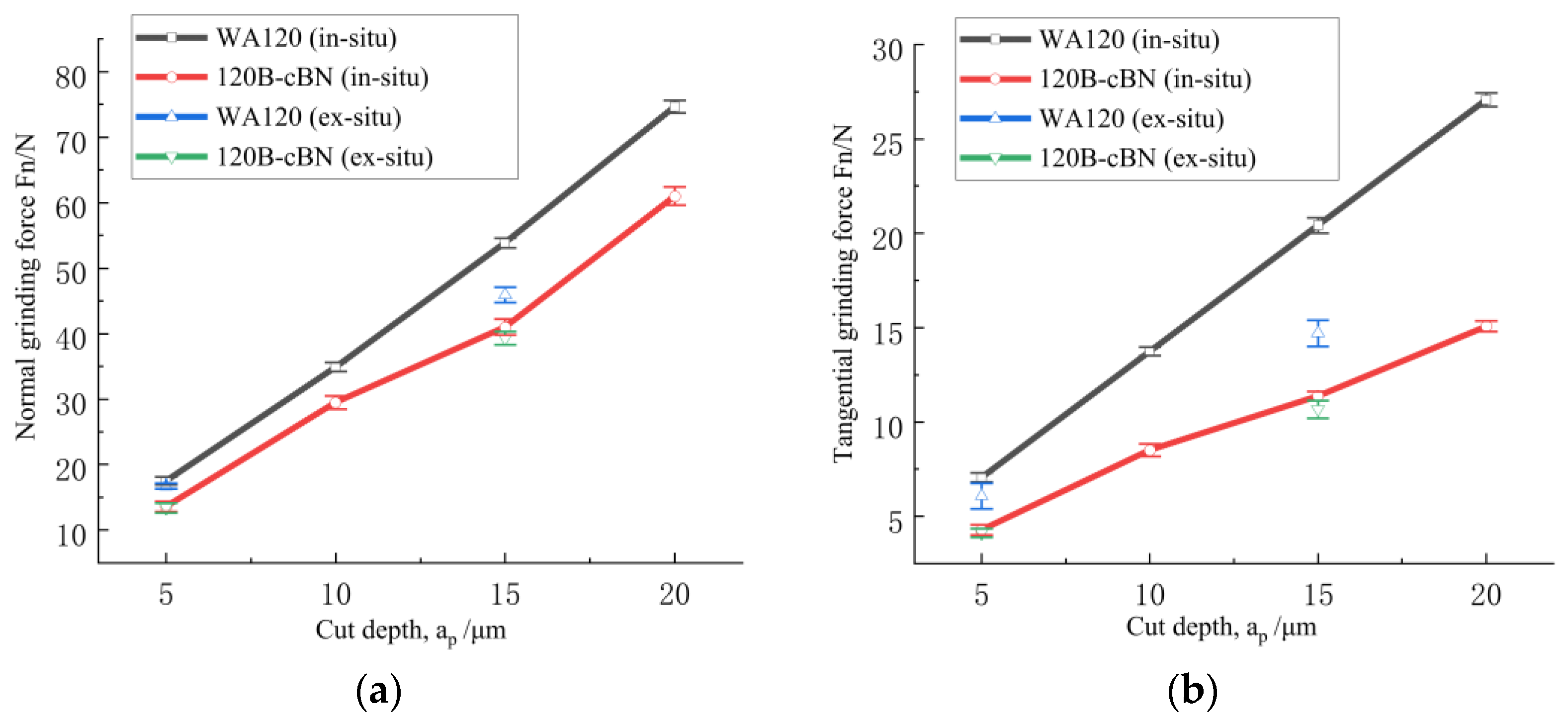
Figure 2 and Figure 3 present the mean values of the normal and tangential grinding force change along with the cut depth, in grinding WC/Fe (in situ and ex situ) coatings with the two wheels, under two different speeds of the grinding wheel. It can be seen that for the two grinding wheels, both the normal grinding force and the tangential grinding force directly increase as the cut depth rises. Additionally, the normal grinding force exhibits much more significant growth with the increase in the cut depth. Similar results were found in grinding SiC/Al composite [30]. In addition, under the same grinding conditions, the grinding forces of the in situ WC/Fe coating are greater than those of the ex situ WC/Fe coating. Meanwhile, the WA120 wheel has greater grinding forces than the 120B-cBN wheel. The variance of the grinding forces for the two different coatings or the two wheels is more significant at the larger cut depth. Moreover, from Figure 2 and Figure 3, one can find that the normal and tangential grinding forces decrease slightly as the grinding wheel speed rises from 23 m/s to 27.2 m/s.
According to the maximum undeformed (uncut) chip thickness theory [31,32], an increment in the cut depth leads to an increment in the maximum uncut chip thickness and the contact area between the workpiece and the grinding wheel, which results in the increase in the chip load per grit. At the same time, the actual participation of grits in the grinding process also increases with the increment in the cut depth, and rubbing among the grinding wheel, grinding chips and the workpiece increases. Therefore, the grinding forces increase [33]. However, with the increment in the wheel speed, both the normal and tangential grinding forces decrease. The reason is that a higher cutting speed leads to a decrement in the maximum uncut chip thickness [18,33]. In addition, the two wheels have different abrasive and bond types, which may result in different effective engagements of the abrasive grits [19]. When grinding in the same conditions, the cBN wheel has smaller grinding forces, which may be attributed to the smaller actual cut depth for per cBN grit. On the other hand, because the microhardness of WC/Fe (in situ) coating is almost twice that of the WC/Fe (ex situ) coating, while their TRS was not obviously different, a larger grinding force is required when grinding the in situ WC/Fe coating, due to more energy being consumed. This is confirmed in the following section.
3.3. Force Ratio and Specific Energy
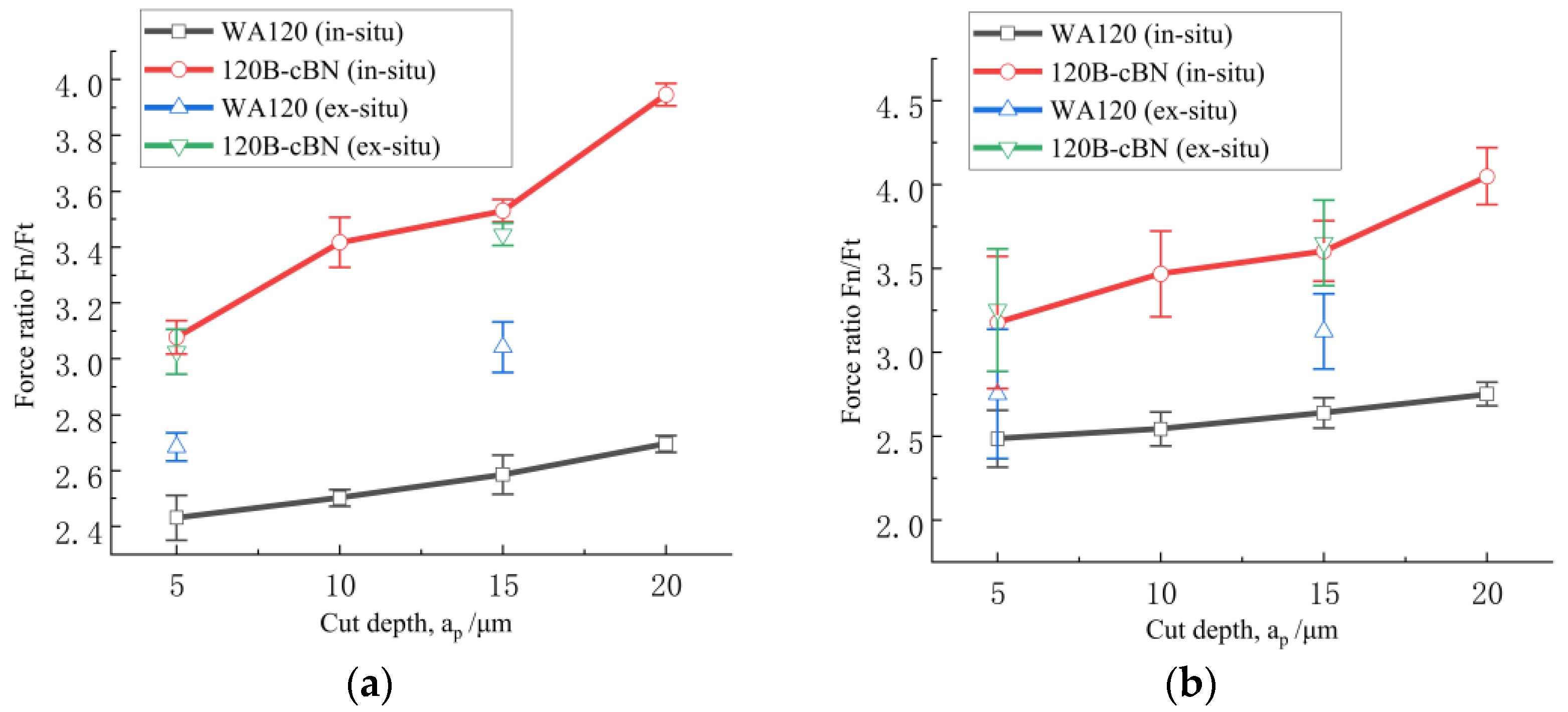
The grinding force ratio (Fn/Ft) reflects the correlation between the abrasives and the workpiece [18]. A higher force ratio is usually related to dullness of the grit, high hardness of the work piece or a smaller maximum uncut chip thickness [32]. Generally, Fn/Ft reduces with an increment in the maximum uncut chip thickness in most cases of metallic alloys, as an increase in the cut depth results in an increment in the maximum uncut chip thickness; thus, the influence of the radius of the grit edge on the removal of material decreases. This occurs as the rake angle posed by the grit is more negative when the uncut chip thickness is smaller [13]. This, in turn, leads to the increase in the force ratio. Figure 4a,b show the relationship between Fn/Ft and the cut depth. One can find that Fn/Ft rises with the increment in the cut depth. This result is different from the case of metallic alloys but similar to the trend in grinding sprayed coatings. This is because the properties of laser clad WC/Fe coatings are similar to that of sprayed coatings to a certain extent, and these coatings are hard and brittle. When grinding such brittle coatings, the mechanism of material removal, in general, comprises plastic flow and brittle fracture, but brittle fracture is the dominating mode [12,33]. So, the roles of plowing, rubbing and microcutting are not obvious; thus, the effect of the maximum undeformed chip thickness on Fn/Ft is limited.
As shown in Figure 4, under the same grinding parameters, the force ratio, Fn/Ft, for the 120B-cBN wheel was greater than that for the WA120 wheel in grinding both coatings, and the difference of Fn/Ft between the two wheels was more obvious when grinding the in situ WC/Fe coating. Additionally, comparing the force ratio for the two coatings, it can be seen that the force ratio for the in situ WC/Fe coating is higher than that for the ex situ WC/Fe coating. At the set grinding conditions in this investigation, the force ratio was 2.4~2.8 for the WA120 wheel; for the 120B-cBN wheel, the force ratio was 3.0~4.3.
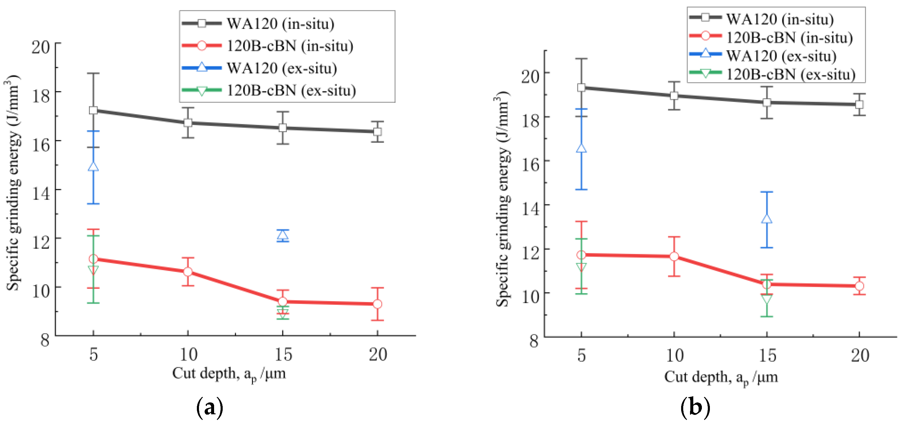
Specific energy represents the energy consumed in removing material per unit volume, which is usually considered to be an important indication to estimate the performance of the grinding wheel or workpiece. Rubbing, plowing and shearing are three elements which contribute to the specific energy in the grinding of metallic alloys; specific energy generally reduces with the increase in the maximum uncut chip thickness or the material removal rate [12]. As presented in Figure 5, the specific energy for the two coatings is low (9–21 J/mm3) and its trend with the cut depth is consistent with the results in metallic alloys. However, its trend with wheel speed is inconsistent with the behavior in metallic alloys, but similar to the results reported in the grinding of sprayed coatings, in which the effect of wheel speed on the tangential force is smaller [33].
Figure 5 displays that the specific energy for the WA120 wheel is higher than that for the 120B-cBN wheel in grinding the two coatings. Moreover, it is much higher for the in situ WC/Fe coating than that for the ex situ WC/Fe coating, when the WA120 wheel is used. However, there is not an obvious difference between the specific grinding energy of the two coatings when the 120B-cBN wheel is used. The main reasons for the above displayed results are owing to the different nature of the wheels and the coatings. Less rubbing between the abrasive grit and the coating leads to a smaller tangential grinding force; therefore, less energy is consumed. The WC/Fe coating containing in situ WC possesses much higher hardness than the coating with ex situ WC, while Al2O3 abrasive has lower hardness compared to cBN grit, which makes it difficult to penetrate the coating, leading to more severe rubbing between the abrasive and the coating surface during grinding, and thus, causing more energy consumption. Meanwhile, the differences in the size and number of defects between the two coatings will lead to different material removal modes. Commonly, the higher the hardness and the more defects the coating has, the more difficult it is for the plastic deformation to take place. As a result, the proportion of brittle fractures increases, causing less energy consumption during the grinding process [13].
3.4. Ground Surface Appearance and Roughness
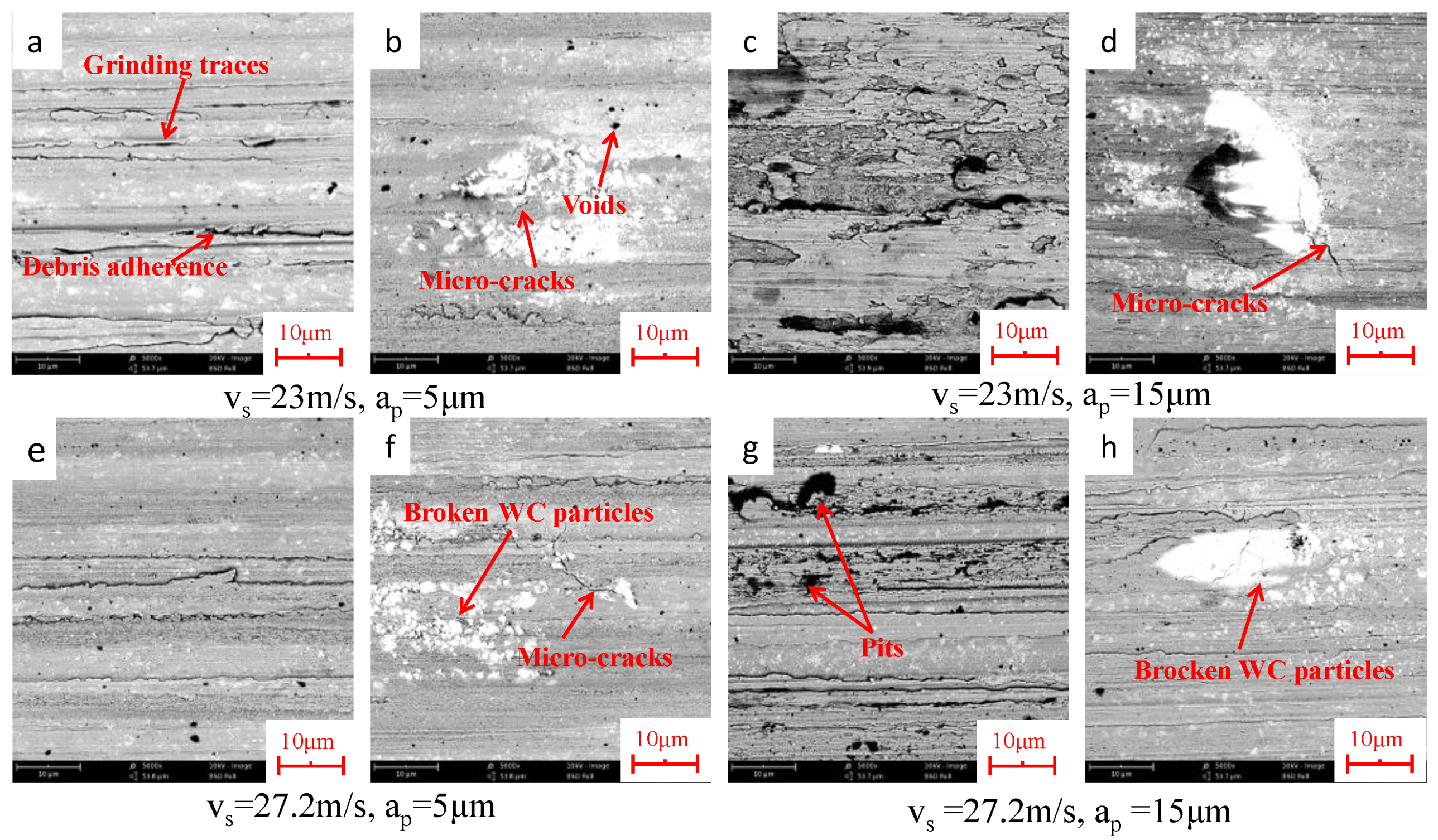
The ground surface appearance can reflect the material removal mechanism during the grinding operation [12,33]. Figure 6 displays the surface appearance of the ex situ WC/Fe coating ground by wheel WA120. At the cut depth of 5 μm, as shown in Figure 6a,b,e,f, grinding traces, debris adherence, voids and microcracks are clearly visible in the base metal; broken WC particles and debris of broken WC particles are also seen on the ground coatings. At the cut depth of 15 μm, the coating surface is severely damaged (Figure 6c,g), and chipping and microcracks prevail on the surface. Pits from the brittle fracture of the iron-based metal and the extracted broken WC particles can be observed (Figure 6c,d,g). Similar types of subsurface damages were observed in the grinding of laser cladding Cr3C2/Ni composite coating and TiCp/Ti–6Al–4V composite [21,34]. Cracks generally propagate from the WC particles to the base metal, and the interface between the WC particles and the base metal is favorable for cracks to generate. This is due to the stress concentration near the WC particles [5]. No apparent change on the ground surface morphology can be observed as the wheel speed changes from 23 m/s to 27.2 m/s.
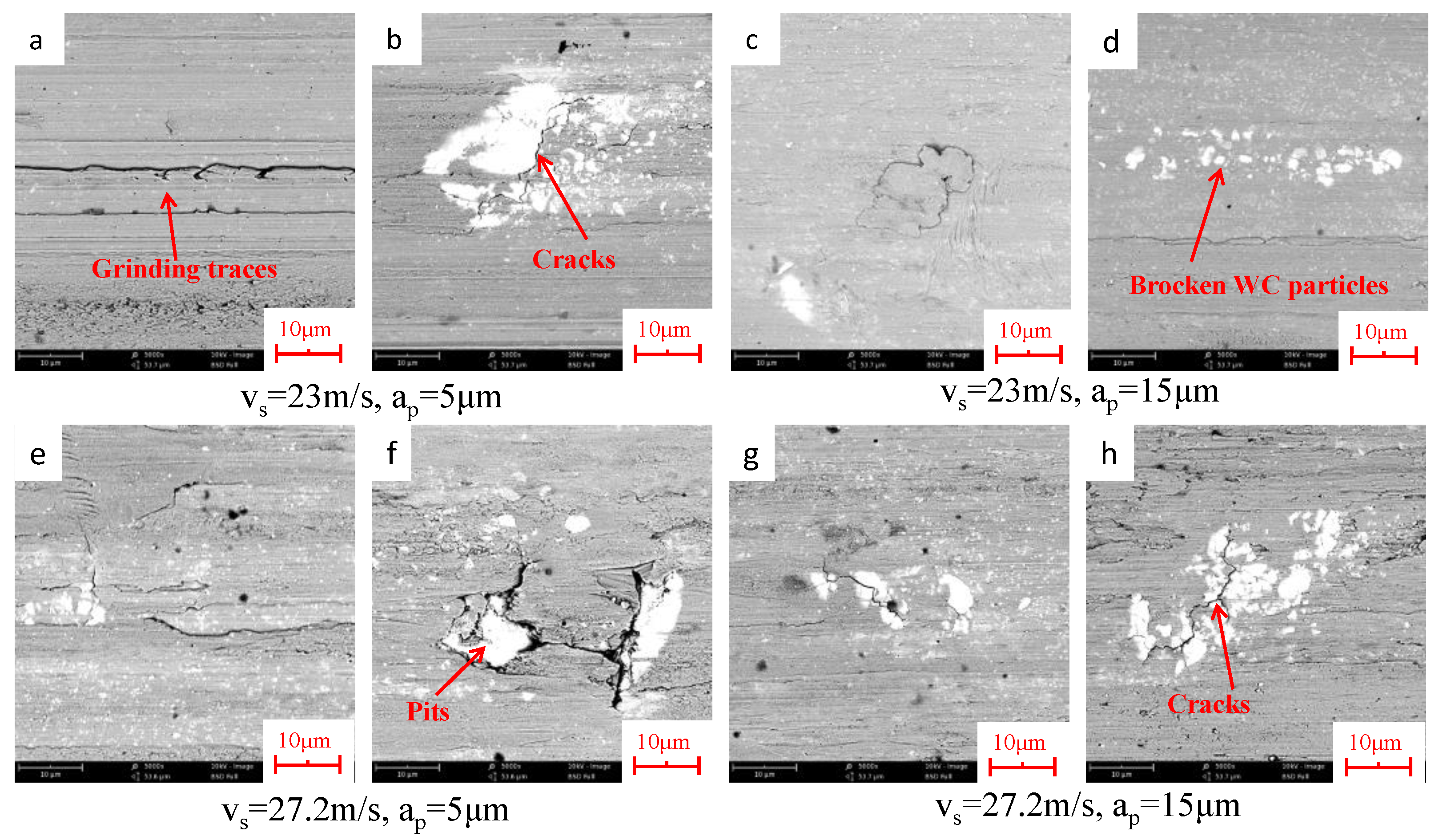
Figure 7 shows the surface appearance of the ex situ WC/Fe coating ground by wheel 120B-cBN. The main defects that appear on the ground surface are similar to those with wheel WA120. However, even when the cut depth is only 5 μm, net cracks and pits resulting from the brittle fractures near the interface between the base metal and the WC particles are observed (Figure 7a,b,e,f).
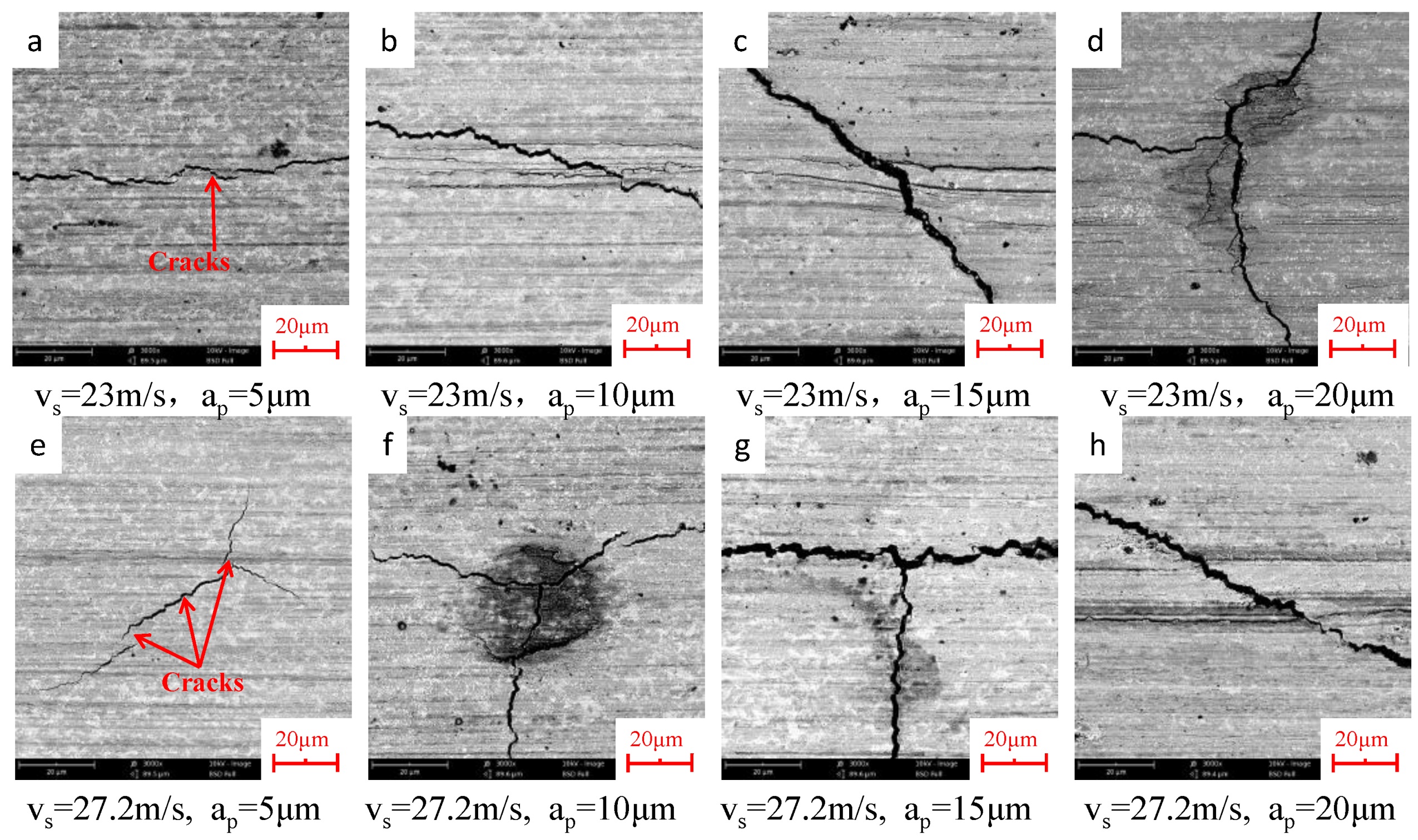
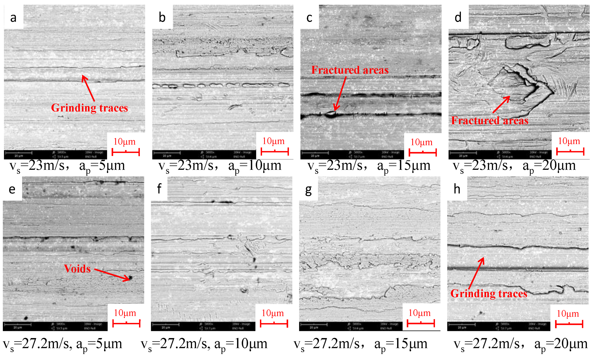
The ground surface appearance of the in situ WC/Fe coating by the two wheels is presented in Figure 8 and Figure 9, respectively. One can find that the ground surface morphology of the coating with in situ WC is obviously different from that of the coating with ex situ WC. No broken WC particles or debris of broken WC particles appear on the ground surface. However, quite a number of cracks are observed on the coating surface ground by the WA120 wheel, even at the cut depth of 5 μm. As the cut depth is raised to 15 μm and above, the number of cracks and the depth and width of the cracks increase significantly, as presented in Figure 8. In contrast, there are no visible cracks but instead there are obvious grinding traces on the coating surface ground by the 120B-cBN wheel. As the cut depth reaches 15 μm and above, deeper grinding traces and fractured areas, owing to the partial breakage of the coating, can be observed; thus, the portion of uneven areas on the ground surface increases (Figure 9c,d,g,h).
The surface roughness (Ra) of the two ground coatings by the WA120 and 120B-cBN wheel is listed in Table 6. It can be seen that under the same grinding conditions, the value of Ra of the ex situ WC/Fe coating is obviously larger than that of the in situ WC/Fe coating.
On the other hand, the value of Ra of both coatings ground by wheel 120B-cBN is much higher than that by wheel WA120. This may be due to the lower grain protrusion of the Al2O3 abrasive because a higher roughness value is produced by a higher grain protrusion [19]. As the wheel speed is raised from 23 m/s to 27.2 m/s, no obvious change in the value of Ra of either coating can be seen. The values of Ra of the ground surface of the two coatings are consistent with the characteristics of the surface morphology as exhibited above.
3.5. Formation Mechanism of Ground Subsurface Damages
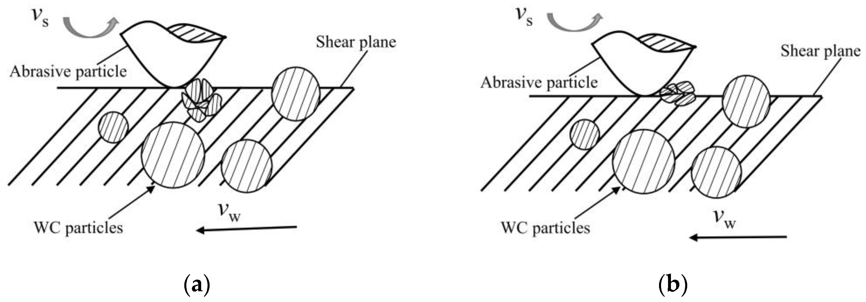
As demonstrated in the above section, the major subsurface damages observed on the ground ex situ WC/Fe coating by the two wheels included grinding traces, debris adherence, pits, microcracks, fractured areas and broken WC particles. The soft ductile Fe base metal is beneficial for plastic deformation. At the small cut depth, scratching and plowing are the dominant effects of the abrasive grits on the coating. As a result, the grinding traces that develop on the ground surface are due to the plastic deformation and plastic flow of the base metal. At the large cut depth, the predominant material removal mode for the base metal changes from plastic flow to brittle fracture, owing to the increase in the grinding force [33,34], which was confirmed according to the relationship between specific energy and the cut depth in the above section; therefore, this gives rise to the formation and propagation of microcracks, as well as the occurrence of brittle fractures, which form the uneven areas and pits on the ground surface. Meanwhile, during the grinding process, if the abrasive grit cuts into the WC particles, the grinding force increases significantly, owing to the hard and brittle character of WC, thus resulting in a large impact on the interface between the WC particles and the base metal, and the breakage of WC particles will be induced [21]. The debris of broken WC particles will be further broken and pressed into the coating in the following grinding process if their protrusion above the shear plane of the abrasive grit is small (as shown in Figure 10a) because the retention capacity of the base metal for WC particles, in this case, is larger than the grinding force. Conversely, the debris of the broken WC particles will be pulled out if their protrusion above the shear plane of the abrasive grit is large (Figure 10b), and pits appear on the ground surface (Figure 6d and Figure 7f,g). With more serious breakage of WC particles, net cracks develop on the surface ground by wheel 120B-cBN. This is because cBN abrasive is much harder than Al2O3 abrasive; thus, cBN grits have a larger impact on WC particles during the grinding process.
The mean subsurface damage observed on the ground in situ WC/Fe coating by the WA120 wheel comprised quite a few cracks, while that observed with the 120B-cBN wheel included only grinding traces seen at the small cut depth, and at the larger cut depth, brittle fracture areas and deeper grinding traces appeared on the ground surface. As previously mentioned, tiny WC particles uniformly disperse in the base metal of the in situ WC/Fe coating, which leads to a weak interaction between the tiny WC particles and the abrasive grain. Moreover, the smaller sized WC particles are not easily broken [35]. However, owing to the dispersion strengthening of the tiny WC particles, and the large amount of tiny WC particles being connected with the base metal to form a skeleton with high wear resistance in the coating, the coating is difficult to plastically deform during the grinding process [36]; therefore, the coating is primarily removed by brittle fracture. cBN grits have higher hardness, which makes it much easier for them to cut into the coating and a smaller grinding force needed. Thus, the coating is not easy to crack when ground by the 120B-cBN wheel. However, Al2O3 abrasive has more difficulty cutting into the hard coating due to its lower hardness, and when ground by the WA120 wheel, great extrusion is induced on the coating due to the compression stress of the abrasives of the wheel, a larger grinding force is conducted and accordingly, a large number of cracks appear.
4. Conclusions
The experimental results in this paper reveal that with the same test conditions, the grinding forces and force ratio of the in situ WC/Fe coating are greater than those of the ex situ WC/Fe coating because the hardness of the former is almost twice as high as the latter. Using the WA120 grinding wheel had a greater grinding force and smaller force ratio than using the 120B-cBN grinding wheel, due to the lower hardness and the smaller protrusion of Al2O3 abrasives. The value of Ra of the ex situ coating (WC/Fe) was obviously bigger than that of the in situ coating. On the other hand, using the 120B-cBN wheel gains a much higher value of Ra than using the WA120 wheel, when grinding the two coatings. The subsurface damages observed on the ground surface of the ex situ WC/Fe coating by the two wheels included grinding traces, debris adherence, pits, cracks, fractured areas and broken WC particles. However, the ground surface morphology of the in situ WC/Fe coating was significantly different to that of the ex situ WC/Fe coating. Moreover, the surface appearance of the in situ WC/Fe coatings ground by the two wheels was distinctly different. Even at a small cut depth, quite a number of cracks were seen on the coating surface when the WA120 wheel was used. No obvious crack was found, but deeper grinding marks and fractured areas appeared on the surface when the 120B-cBN wheel was used. Therefore, through the comprehensive assessment of this investigation, one can find that for grinding the ex situ WC/Fe coating, the WA120 wheel is more suitable than the 120B-cBN wheel, but for grinding the in situ WC/Fe coating, the 120B-cBN wheel is more appropriate than the WA120 wheel.
Regarding the experimental results in the present work, there were severe subsurface damages on the ground coatings. A deeper study of the formation mechanism of the subsurface damages is needed. In addition, further grinding performance research should be carried out to find an appropriate grinding process to eliminate or reduce the grinding defects.
Author Contributions
Conceptualization, Q.D.; Methodology, Q.D. and L.L.; Validation, F.Y. and Q.D.; Investigation, Q.D. and C.L.; Resources, F.Y. and Q.D.; Data curation, L.L.; Writing—original draft preparation, L.L. and Q.D.; Writing—review and editing, Q.D. and L.L. All authors have read and agreed to the published version of the manuscript.
Funding
This study was supported by the National Natural Science Foundation of China (Grant No. 51375180).
Data Availability Statement
The data presented in this study are available on request from the corresponding author.
Acknowledgments
The authors would like to thank Gaoxu Li for his contribution of experimental data.
Conflicts of Interest
The authors declare no conflict of interest.
References
- Song, M.; Wu, L.; Liu, J.; Hu, Y. Effects of Laser Cladding on Crack Resistance Improvement for Aluminum Alloy Used in Aircraft Skin. Opt. Laser Technol. 2021, 133, 106531. [Google Scholar] [CrossRef]
- Wang, X.; Lei, L.; Yu, H. A Review on Microstructural Features and Mechanical Properties of Wheels/Rails Cladded by Laser Cladding. Micromachines 2021, 12, 152. [Google Scholar] [CrossRef] [PubMed]
- Kattire, P.; Paul, S.; Singh, R.; Yan, W. Experimental Characterization of Laser Cladding of CPM 9V on H13 Tool Steel for Die Repair Applications. J. Manuf. Process. 2015, 20, 492–499. [Google Scholar] [CrossRef]
- Rahman Rashid, R.A.; Barr, C.J.; Palanisamy, S.; Nazari, K.A.; Orchowski, N.; Matthews, N.; Dargusch, M.S. Effect of Clad Orientation on the Mechanical Properties of Laser-Clad Repaired Ultra-High Strength 300 M Steel. Surf. Coat. Technol. 2019, 380, 125090. [Google Scholar] [CrossRef]
- Xu, J.-S.; Zhang, X.-C.; Xuan, F.-Z.; Tian, F.-Q.; Wang, Z.-D.; Tu, S.-T. Tensile Properties and Fracture Behavior of Laser Cladded WC/Ni Composite Coatings with Different Contents of WC Particle Studied by in-Situ Tensile Testing. Mater. Sci. Eng. A 2013, 560, 744–751. [Google Scholar] [CrossRef]
- Bartkowski, D.; Młynarczak, A.; Piasecki, A.; Dudziak, B.; Gościański, M.; Bartkowska, A. Microstructure, Microhardness and Corrosion Resistance of Stellite-6 Coatings Reinforced with WC Particles Using Laser Cladding. Opt. Laser Technol. 2015, 68, 191–201. [Google Scholar] [CrossRef]
- Li, X.; Feng, Y.; Liu, B.; Yi, D.; Yang, X.; Zhang, W.; Chen, G.; Liu, Y.; Bai, P. Influence of NbC Particles on Microstructure and Mechanical Properties of AlCoCrFeNi High-Entropy Alloy Coatings Prepared by Laser Cladding. J. Alloy. Compd. 2019, 788, 485–494. [Google Scholar] [CrossRef]
- Lee, C.; Park, H.; Yoo, J.; Lee, C.; Woo, W.; Park, S. Residual Stress and Crack Initiation in Laser Clad Composite Layer with Co-Based Alloy and WC + NiCr. Appl. Surf. Sci. 2015, 345, 286–294. [Google Scholar] [CrossRef]
- Lu, J.Z.; Cao, J.; Lu, H.F.; Zhang, L.Y.; Luo, K.Y. Wear Properties and Microstructural Analyses of Fe-Based Coatings with Various WC Contents on H13 Die Steel by Laser Cladding. Surf. Coat. Technol. 2019, 369, 228–237. [Google Scholar] [CrossRef]
- Tran, V.N.; Yang, S.; Phung, T.A. Microstructure and Properties of Cu/TiB2 Wear Resistance Composite Coating on H13 Steel Prepared by in-Situ Laser Cladding. Opt. Laser Technol. 2018, 108, 480–486. [Google Scholar] [CrossRef]
- Fernández, M.R.; García, A.; Cuetos, J.M.; González, R.; Noriega, A.; Cadenas, M. Effect of Actual WC Content on the Reciprocating Wear of a Laser Cladding NiCrBSi Alloy Reinforced with WC. Wear 2015, 324–325, 80–89. [Google Scholar] [CrossRef]
- Liu, X.; Zhang, B.; Deng, Z. Grinding of Nanostructured Ceramic Coatings: Surface Observations and Material Removal Mechanisms. Int. J. Mach. Tools Manuf. 2002, 42, 1665–1676. [Google Scholar] [CrossRef]
- Kar, S.; Bandyopadhyay, P.P.; Paul, S. Precision Superabrasive Grinding of Plasma Sprayed Ceramic Coatings. Ceram. Int. 2016, 42, 19302–19319. [Google Scholar] [CrossRef]
- Pishva, P.; Salehi, M.; Golozar, M.A. Effect of Grinding on Surface Characteristics of HVOF-Sprayed WC–10Co–4Cr Coatings. Surf. Eng. 2020, 36, 1180–1189. [Google Scholar] [CrossRef]
- Zoei, M.S.; Sadeghi, M.H.; Salehi, M. Effect of Grinding Parameters on the Wear Resistance and Residual Stress of HVOF-Deposited WC–10Co–4Cr Coating. Surf. Coat. Technol. 2016, 307, 886–891. [Google Scholar] [CrossRef]
- Ghosh, G.; Sidpara, A.; Bandyopadhyay, P.P. Theoretical and Experimental Investigation of Material Removal Rate in Shape Adaptive Grinding of HVOF Sprayed WC-Co Coating. Precis. Eng. 2021, 72, 627–639. [Google Scholar] [CrossRef]
- Huang, H.; Liu, Y.C. Experimental Investigations of Machining Characteristics and Removal Mechanisms of Advanced Ceramics in High Speed Deep Grinding. Int. J. Mach. Tools Manuf. 2003, 43, 811–823. [Google Scholar] [CrossRef]
- Kar, S.; Bandyopadhyay, P.P.; Paul, S. High Speed and Precision Grinding of Plasma Sprayed Oxide Ceramic Coatings. Ceram. Int. 2017, 43, 15316–15331. [Google Scholar] [CrossRef]
- Rausch, S.; Biermann, D. Grinding of Hard-Material-Coated Forming Tools on Machining Centers. Procedia CIRP 2012, 1, 388–392. [Google Scholar] [CrossRef] [Green Version]
- Lin, Y.; Dong, S.; Tian, X.; Ba, G. Electrochemical Grinding of Hard and Ductile Tooth Surfaces Fabricated by Laser Cladding. CHINA Surf. Eng. 2009, 22, 53–55+60. [Google Scholar]
- Dai, Q.; Zhang, J.; You, F. Grinding characteristics of laser cladding Cr3C2 /Ni based composite coating. J. Harbin Inst. Technol. 2019, 51, 122. [Google Scholar] [CrossRef]
- Yu, T.; Deng, Q.; Dong, G.; Yang, J. Effects of Ta on Microstructure and Microhardness of Ni Based Laser Clad Coating. Appl. Surf. Sci. 2011, 257, 5098–5103. [Google Scholar] [CrossRef]
- Zhong, L.; Zhang, X.; Chen, S.; Xu, Y.; Wu, H.; Wang, J. Fe–W–C Thermodynamics and in Situ Preparation of Tungsten Carbide-Reinforced Iron-Based Surface Composites by Solid-Phase Diffusion. Int. J. Refract. Met. Hard Mater. 2016, 57, 42–49. [Google Scholar] [CrossRef]
- Bartkowski, D.; Bartkowska, A.; Jurči, P. Laser cladding process of Fe/WC metal matrix composite coatings on low carbon steel using Yb: YAG disk laser. Opt. Laser Technol. 2021, 136, 106784. [Google Scholar] [CrossRef]
- Xiao, Q.; Sun, W.L.; Yang, K.X.; Xing, X.F.; Chen, Z.H.; Zhou, H.N.; Lu, J. Wear Mechanisms and Micro-Evaluation on WC Particles Investigation of WC-Fe Composite Coatings Fabricated by Laser Cladding. Surf. Coat. Technol. 2021, 420, 127341. [Google Scholar] [CrossRef]
- Zhou, S.; Xu, Y.; Liao, B.; Sun, Y.; Dai, X.; Yang, J.; Li, Z. Effect of Laser Remelting on Microstructure and Properties of WC Reinforced Fe-Based Amorphous Composite Coatings by Laser Cladding. Opt. Laser Technol. 2018, 103, 8–16. [Google Scholar] [CrossRef] [Green Version]
- Dai, Q.-L.; Luo, C.-B.; You, F.-Y. Crack Restraining Methods and Their Effects on the Microstructures and Properties of Laser Cladded WC/Fe Coatings. Materials 2018, 11, 2541. [Google Scholar] [CrossRef] [Green Version]
- Wang, J.; Li, L.; Tao, W. Crack Initiation and Propagation Behavior of WC Particles Reinforced Fe-Based Metal Matrix Composite Produced by Laser Melting Deposition. Opt. Laser Technol. 2016, 82, 170–182. [Google Scholar] [CrossRef]
- Yao, C.; Huang, J.; Zhang, P.; Li, Z.; Wu, Y. Toughening of Fe-Based Laser-Clad Alloy Coating. Appl. Surf. Sci. 2011, 257, 2184–2192. [Google Scholar] [CrossRef]
- Di Ilio, A.; Paoletti, A. A Comparison between Conventional Abrasives and Superabrasives in Grinding of SiC-Aluminium Composites. Int. J. Mach. Tools Manuf. 2000, 40, 173–184. [Google Scholar] [CrossRef]
- Zhang, D.; Li, C.; Jia, D.; Zhang, Y. Investigation into Engineering Ceramics Grinding Mechanism and the Influential Factors of the Grinding Force. Int. J. Control Autom. 2014, 7, 19–34. [Google Scholar] [CrossRef]
- Vashista, M.; Paul, S. Study of the Effect of Process Parameters in High-Speed Grinding on Surface Integrity by Barkhausen Noise Analysis. Proc. Inst. Mech. Eng. Part B J. Eng. Manuf. 2008, 222, 1625–1637. [Google Scholar] [CrossRef]
- Masoumi, H.; Safavi, S.M.; Salehi, M. Grinding Force, Specific Energy and Material Removal Mechanism in Grinding of HVOF-Sprayed WC–Co–Cr Coating. Mater. Manuf. Process. 2014, 29, 321–330. [Google Scholar] [CrossRef]
- Li, Z.; Ding, W.; Shen, L.; Xi, X.; Fu, Y. Comparative Investigation on High-Speed Grinding of TiCp/Ti–6Al–4V Particulate Reinforced Titanium Matrix Composites with Single-Layer Electroplated and Brazed CBN Wheels. Chin. J. Aeronaut. 2016, 29, 1414–1424. [Google Scholar] [CrossRef] [Green Version]
- Gong, T.; Yao, P.; Zuo, X.; Zhang, Z.; Xiao, Y.; Zhao, L.; Zhou, H.; Deng, M.; Wang, Q.; Zhong, A. Influence of WC Carbide Particle Size on the Microstructure and Abrasive Wear Behavior of WC–10Co–4Cr Coatings for Aircraft Landing Gear. Wear 2016, 362–363, 135–145. [Google Scholar] [CrossRef]
- Chen, X.; Hu, K.; Yuan, Q. Microstructure and Performance of WC Reinforced Fe-based Composite Coating Synthesized In-situ Produced by Laser Cladding. China Surf. Eng. 2016, 29, 118–124. [Google Scholar] [CrossRef]
Figure 1.
Microstructures of in situ and ex situ WC/Fe coatings. (a) In situ WC/Fe coating; (b) ex situ WC/Fe coating.
Figure 1.
Microstructures of in situ and ex situ WC/Fe coatings. (a) In situ WC/Fe coating; (b) ex situ WC/Fe coating.

Figure 2.
Grinding forces of in situ and ex situ WC/Fe coatings by two types of wheels. (vs = 23 m/s): (a) normal grinding force; (b) tangential grinding force.
Figure 2.
Grinding forces of in situ and ex situ WC/Fe coatings by two types of wheels. (vs = 23 m/s): (a) normal grinding force; (b) tangential grinding force.

Figure 3.
Grinding forces of in situ and ex situ WC/Fe coatings by two types of wheels. (vs = 27.2 m/s): (a) normal grinding force; (b) tangential grinding force.
Figure 3.
Grinding forces of in situ and ex situ WC/Fe coatings by two types of wheels. (vs = 27.2 m/s): (a) normal grinding force; (b) tangential grinding force.

Figure 4.
Grinding force ratio of in situ and ex situ WC/Fe coatings by two types of wheels. (a) vs = 23 m/s; (b) vs = 27.2 m/s.
Figure 4.
Grinding force ratio of in situ and ex situ WC/Fe coatings by two types of wheels. (a) vs = 23 m/s; (b) vs = 27.2 m/s.

Figure 5.
Specific grinding energy of in situ and ex situ WC/Fe coatings by two types of wheels. (a) vs = 23 m/s; (b) vs = 27.2 m/s.
Figure 5.
Specific grinding energy of in situ and ex situ WC/Fe coatings by two types of wheels. (a) vs = 23 m/s; (b) vs = 27.2 m/s.

Figure 6.
Ground surface morphology of ex situ WC/Fe coatings by WA120 wheel. (a,b) vs = 23 m/s, ap = 5 μm; (c,d) vs = 23 m/s, ap = 15 μm; (e,f) vs = 27.2 m/s, ap = 5 μm; (g,h) vs = 27.2 m/s, ap = 15 μm.
Figure 6.
Ground surface morphology of ex situ WC/Fe coatings by WA120 wheel. (a,b) vs = 23 m/s, ap = 5 μm; (c,d) vs = 23 m/s, ap = 15 μm; (e,f) vs = 27.2 m/s, ap = 5 μm; (g,h) vs = 27.2 m/s, ap = 15 μm.

Figure 7.
Ground morphology of ex situ WC/Fe coatings using 120B-cBN wheel. (a,b) vs = 23 m/s, ap = 5 μm; (c,d) vs = 23 m/s, ap = 15 μm; (e,f) vs = 27.2 m/s, ap = 5 μm; (g,h) vs = 27.2 m/s, ap = 15 μm.
Figure 7.
Ground morphology of ex situ WC/Fe coatings using 120B-cBN wheel. (a,b) vs = 23 m/s, ap = 5 μm; (c,d) vs = 23 m/s, ap = 15 μm; (e,f) vs = 27.2 m/s, ap = 5 μm; (g,h) vs = 27.2 m/s, ap = 15 μm.

Figure 8.
Ground surface morphology of in situ WC/Fe coatings by WA120 wheel. (a) vs = 23 m/s, ap = 5 μm; (b) vs = 23 m/s, ap = 10 μm; (c) vs = 23 m/s, ap = 15 μm; (d) vs = 23 m/s, ap = 20 μm; (e) vs = 27.2 m/s, ap = 5 μm; (f) vs = 27.2 m/s, ap = 10 μm; (g) vs = 27.2 m/s, ap = 15 μm; (h) vs = 27.2 m/s, ap = 20 μm.

Figure 9.
Ground surface morphology of in situ WC/Fe coatings by 120B-cBN wheel. (a) vs = 23 m/s, ap = 5 μm; (b) vs = 23 m/s, ap = 10 μm; (c) vs = 23 m/s, ap = 15 μm; (d) vs = 23 m/s, ap = 20 μm; (e) vs = 27.2 m/s, ap = 5 μm; (f) vs = 27.2 m/s, ap = 10 μm; (g) vs = 27.2 m/s, ap = 15 μm; (h) vs = 27.2 m/s, ap = 20 μm.

Figure 10.
(a) In situ indentation mechanism of WC particles; (b) pulled-out mechanism of WC particles.
Figure 10.
(a) In situ indentation mechanism of WC particles; (b) pulled-out mechanism of WC particles.


Table 1.
Chemical composition of Fe314 (wt.%).
| Cr | Ni | B | Si | C | Fe |
|---|---|---|---|---|---|
| 14.8~15.2 | 9.2~11.1 | 0.9~1.1 | 0.9~1.1 | 0.09~0.1 | Bal. |
Table 2.
Chemical composition of Rockit701 (wt.%).
| C 0.98 | W 9.1 | Mn 1.3 | Cr 3.5 | Si 1.4 |
|---|---|---|---|---|
| B | V | Ti | Ni | Fe |
| 0.85 | 1.8 | 0.3 | 1.6 | Bal. |
Table 3.
Specifications of the grinding wheels.
| Grinding Wheel Identification | Diameter/Width (mm) | Abrasive | Grit Size | Bond Type |
|---|---|---|---|---|
| WA120 | 200/13 | Al2O3 | 120 | V |
| 120-cBN | 200/13 | cBN | 120 | B |
Table 4.
Grinding parameters.
| Coatings | In Situ WC/Fe Coating | Ex situ WC/Fe Coating | |
|---|---|---|---|
| Grinding Parameters | |||
| Grinding wheel | WA120, 120B-cBN | WA120, 120B-cBN | |
| Wheel speed (m/s) | 23, 27.2 | 23, 27.2 | |
| Cut depth (μm) | 5, 10, 15, 20 | 515 | |
| Grinding method | dry grinding | dry grinding | |
| Feed rate (m/s) | 0.2 | 0.2 | |
Table 5.
Microhardness and TRS of in situ and ex situ WC/Fe coatings.
| Coating | Hardness/HV0.2 | Error | TRS/Mpa | Error |
|---|---|---|---|---|
| In situ WC/Fe coating | 948.07 | 3.3% | 1022.75 | 9.5% |
| Ex situ WC/Fe coating | 508.15 | 2.7% | 1102.06 | 10.3% |
Table 6.
Ground surface roughness of in situ and ex situ WC/Fe coatings by two types of wheels.
| Grinding Wheel Identification | Wheel Speed (m/s) | Cut Depth (μm) | Ra of Ex Situ WC/Fe Coating (μm) | Error | Ra of In Situ WC/Fe Coating (μm) | Error |
|---|---|---|---|---|---|---|
| WA120 | 23 | 5 | 0.18 | 5.6% | 0.09 | 10% |
| 120B-cBN | 23 | 5 | 0.51 | 5.9% | 0.34 | 2.9% |
| WA120 | 27.2 | 5 | 0.16 | 6.3% | 0.06 | 16.7% |
| 120B-cBN | 27.2 | 5 | 0.52 | 1.9% | 0.29 | 6.9% |
Publisher’s Note: MDPI stays neutral with regard to jurisdictional claims in published maps and institutional affiliations. |
© 2022 by the authors. Licensee MDPI, Basel, Switzerland. This article is an open access article distributed under the terms and conditions of the Creative Commons Attribution (CC BY) license (https://creativecommons.org/licenses/by/4.0/).
Share and Cite
MDPI and ACS Style
Dai, Q.; Liu, L.; You, F.; Luo, C. Grinding Performance of Laser Cladding WC/Fe Coatings by Different Adding Methods of WC Particles. Machines 2022, 10, 910. https://doi.org/10.3390/machines10100910
AMA Style
Dai Q, Liu L, You F, Luo C. Grinding Performance of Laser Cladding WC/Fe Coatings by Different Adding Methods of WC Particles. Machines. 2022; 10(10):910. https://doi.org/10.3390/machines10100910
Chicago/Turabian StyleDai, Qiulian, Lianhong Liu, Fangyi You, and Canbin Luo. 2022. "Grinding Performance of Laser Cladding WC/Fe Coatings by Different Adding Methods of WC Particles" Machines 10, no. 10: 910. https://doi.org/10.3390/machines10100910
Note that from the first issue of 2016, this journal uses article numbers instead of page numbers. See further details here.