
Design and Hydrodynamic Experiment Research on Novel Biomimetic Pectoral Fins of a Ray-Inspired Robotic Fish


Robotics Institute, Beihang University, Beijing 100191, China
*
Author to whom correspondence should be addressed.
Machines 2022, 10(8), 606; https://doi.org/10.3390/machines10080606
Submission received: 16 June 2022
/
Revised: 11 July 2022
/
Accepted: 18 July 2022
/
Published: 25 July 2022
(This article belongs to the Special Issue Advances in Underwater Robot Technology)
Abstract
:Bionic propulsion has certain advantages over traditional propellers. Much research on pectoral fins as bionic propellers for ray-inspired robots has been made, but rarely did they compare the hydrodynamic performance of different fins on the same platform to find out optimal balance. In this paper, the existing prototypes are categorized into three structure types, and a new bionic pectoral fin module used on a ray-inspired robotic fish was presented, together with a novel 2-DOF spatial parallel mechanism as the bionic propeller. Motion analysis of the mechanism agreed well with the pectoral fin kinematic model, providing a reliable basis to test different types of fins. Design and fabrication of the new bionic fin module as well as two traditional ones are also explained. Hydrodynamic experiment was conducted to study the differences between each fin type under various working conditions. Results indicate that the thrust generated by the fin oscillation is closely related to four parameters (amplitude, frequency, phase difference, and flow velocity), and there are optimal value ranges for better propelling performance when the frequency is around 0.5 Hz and phase difference is near 30°. Thanks to better profile preservation and hydro force interaction, the newly proposed pectoral fins had higher performance than the traditional ones in terms of thrust generation and controllability when the amplitude is higher than 30° and frequency is over 0.3 Hz. An average thrust of 2.98 N was recorded for the new fin module at the max amplitude of 60°, 11.6% and 16.4% higher than the other two comparative test groups, respectively.
1. Introduction
Autonomous underwater vehicles (AUVs) have a variety of applications like enemy reconnaissance and resource exploration in military or civilian operations. Traditional AUVs utilize blade propellers as actuators [1,2]. They can generate greater thrust force and reach higher speed but the cavitation effect under high rotation speed will also cause higher noise and lower efficiency [3]. To compensate for these shortcomings, researchers find inspiration from fish and other aquatic creatures to develop various kinds of underwater robots based on the principle of bionic propulsion [4,5,6,7].
There are two main types of fish propulsion mode: MPF (median-paired fin) and BCF (body-caudal Fin) [8]. Either of them has its own advantages: Fish using BCF mode generate thrust through trunk bending and caudal fin swing, capable of swimming at high speed with high efficiency and fast acceleration [9,10,11], while fish with MPF mode gain advantages in propulsion efficiency, maneuverability and noise control at a lower speed range [12,13]. Myliobatidae like cownose rays and manta rays are the representatives of MPF mode. Their large and flat body provides more carrier space and higher payload than fusiform fish (mostly BCF mode). Their delta-shaped wide pectoral fins can realize vectorial propulsion, functioning as the propeller and rudder simultaneously, and the relatively high aspect ratio brings excellent gliding efficiency that allows them to travel thousands of miles without rest [14,15].
The pectoral fin oscillation of rays can be seen as a coupling motion of span-wise flapping and chord-wise pitching, driven and conducted by the muscles and cartilages of the highly flexible fin organism [16,17]. The high control freedom of the pectoral fins and relatively better payload capacity of rays have drawn interest from many researchers in the field of bionic underwater robots [18,19,20,21,22,23,24,25,26,27,28,29,30]. Lots of related research has been made trying to achieve the performance of the original creatures, but due to the volume/weight of the actuators, structural and control complexity or other limitations, the existing prototypes were either oversimplified for engineering feasibility and cannot reproduce the flexible characteristics of the real pectoral fins [19], or trying new actuating methods with fully soft materials at the cost of low speed and payload capacity [22]. As the essential part of the whole bionic system, the structure of the pectoral fins on existing ray-inspired robotic fish can be divided into three types:
- (I)
- 2-Dimensional fins with flexible skeleton or smart actuator;
- (II)
- 3-Dimensional fins with flexible skeleton and permeable skin;
- (III)
- 3-Dimensional fins with rigid skeleton and flexible silicon body.
Considerable simplification is performed on Type-I, ignoring the tridimensional shape of the original fin and its streamlined profile. Most of them consist of a flexible rod in the leading edge as skeleton (calcified cartilages) and a 2D membrane connected to the rod as fin surface. Such structures are either driven by motors or servos connected to the front rod [20,21] or smart actuators as the front rod [22,23]. Both can only perform the span-wise flapping motion and have to rely on the passive deformation of the soft fin membrane to form chord-wise pitching motion, leading to relatively poor maneuverability since the fin has a single degree of freedom that only generates forward thrust.
Efforts were made to fix this problem and Type-II was developed. The flexible skin with supporting keels can preserve the 3D shape of the original fin at a static condition, and extra actuators were added to achieve multi-DOF control and better maneuverability [24,25,26,27], but the material rigidity of the inner skeleton and outer skin are so different that they cannot match well under movement and hydro forces. Prototypes with such fin structures usually have lower swimming speeds compared to Type-I.
A possible solution is replacing the hollow skin with solid soft material like silicon rubber. The fin structure of Type-III can better preserve the 3D shape of the fin profile during motion, but this may also lead to lower energy efficiency since much higher torque is required for the inner skeletons to overcome the elastic damping force in solid rubber to achieve proper fin deformation, especially for those with multi-DOF [28,29]. Although this problem can be alleviated by setting only one skeleton/rod at the leading edge [30], the reduced controllability of the fin deformation will lead to poorer maneuverability, just like prototypes of Type-I.
Most of the above research mainly focused on a single type of pectoral fin that performed well in certain conditions only on their own robot fish. It’s hard to tell whether the performance gap was caused by the fin structure or the difference of their operating platforms and environments. In this paper, a ray-inspired robotic fish with a novel 2-DOF spatial mechanism and 3-dimensional soft pectoral fins as the bionic propellers is presented. Hydrodynamic performance of our newly proposed fin module, as well as two other traditional structure types, will be tested and compared on the same operating platform with identical groups of motion parameters and environment, offering an optimal solution for the design and control of the bio-inspired underwater robots.
This article will be structured as follows. In Section 2, the kinematic model of the cownose ray pectoral fin is first established. Then, as the basis of the bionic propeller, a novel 2-DOF spatial parallel mechanism is designed and analyzed to reproduce the coupled motion of flapping and pitching described by the kinematic model. Later, the design and fabrication of the bionic pectoral fins with high-fidelity 3D profile and bionic softness are briefly explained, as well as the ray-inspired robot fish platform. In Section 3, hydrodynamic experiments are carried out, and the thrust force of three different fin modules on the same robot platform is respectively recorded. To further investigate the performance of each fin type under different groups of motion parameters (amplitude, frequency, phase difference, and flow velocity), the results are discussed in Section 4. Finally, conclusions and future work are listed in Section 5.
2. Materials and Methods
2.1. Kinematic Model of the Pectoral Fin
Morphology and kinematics are the essential elements of a bionic robot ray, similar to other biomimetic research. Rhinoptera bonasus (cownose ray) is characterized by its streamlined flat body and the delta-shaped pectoral fins on either side with a high aspect ratio. While morphology study gives the robot geometrical similarity in the static condition, kinematic observation and modeling play an important role in reproducing the motion behavior of the natural creature and determine the hydrodynamic performance of the robot fish.
The locomotion of the cownose ray can be further categorized as “oscillation mode” when the motion wave traveling on the pectoral fins is less than 0.5 [16]. It can be seen as a coupling motion of span-wise flapping and chord-wise pitching. First, the basal part of the fin flaps upwards (or downwards), then the distal part is dragged to move as well, creating a parabolic curvature with a little time delay (phase difference) from the fin root to fin tip. Meanwhile, the flexible deformation of the fin surface forms a pitching motion under the action of controlling muscles and hydro forces, creating an increasing angle of attack from the fin root to the fin tip.
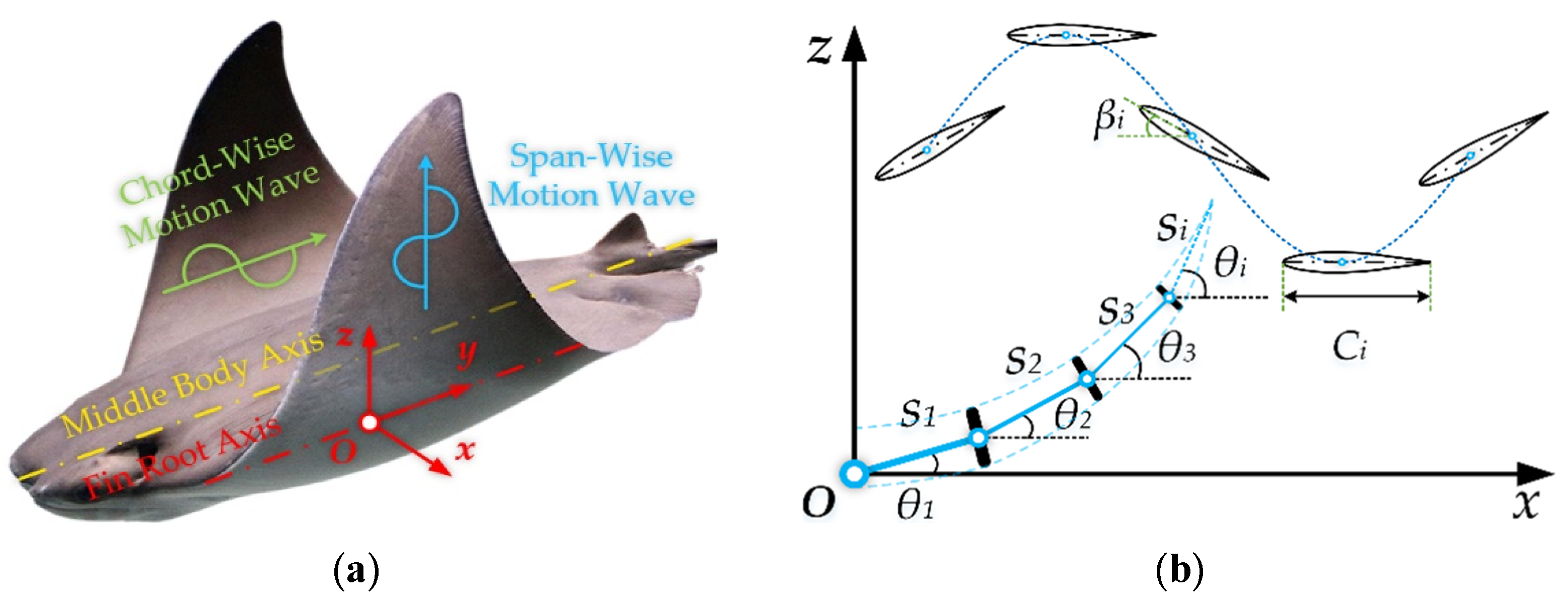
A coordinate system of the pectoral fin is established to describe its locomotion clearly, as shown in Figure 1a. The body axis is along the chord-wise direction and that goes across the mass center and links the head and tail of the fish. The fin axis is parallel to the body axis and is defined as the fin root. The origin was set at the 1/3 length point on the chord line of the fin root. Axis y overlaps with the fin root axis and points backward, axis x is perpendicular to y, and axis z is determined by the right-hand rule. To better describe the kinematic feature of different locations on the pectoral fin, a bionic multi-linkage system is established based on the distribution pattern of the fin cartilage network [31], as shown in Figure 1b.
The fin is discretized along the longest fin ray from root to tip, into a group of links or segments connected by a series of joints at the maximum number of n. For arbitrary segment i, it rotates around the former joint at a certain angular velocity, and there is a time delay (phase difference) between the neighboring segments. Define S as the normal distance from joint n to axis x which also represents the maximum span length, then S = nsi if all segments are of equal length. The oscillation of the pectoral fin can be described by the kinematic model as follows:
where αi is the flapping angle of segment si around axis y; βi is the pitching angle of the chord line Ci around axis x; ψ1 and ψ2 are the phase differences between the neighboring segments. According to motion analysis of the real fin based on the swimming video frames of the cownose ray taken in an aquarium [32], essential motion parameters can be extracted. The maximum flapping amplitude is αmax ≈ 60° and the maximum pitching angle is βmax ≈ 30°. Moreover, the flapping and pitching frequency, f1 and f2, are equal at a range of about 0.3~0.5 Hz, and there is also a 90° phase delay between ψ1 and ψ2.
2.2. Design and Analysis of the Bionic Propelling Mechanism
As shown in the kinematic model Formula (1), the locomotion of the pectoral fin can be decoupled into the span-wise flapping and chord-wise pitching motion. The anatomical study results have proved that fin muscles are thicker and stronger at the basal part, while the distal part consists of more soft tissue and flexible cartilages [17,31], indicating that the basal part of the fin functions as the main actuating power source to generate motion waves, while the distal part is more of a controller to adjust the waves transfer on the fin surface. Based on the above features, a novel bionic propelling mechanism capable of reproducing the locomotion pattern near the fin root was first designed.
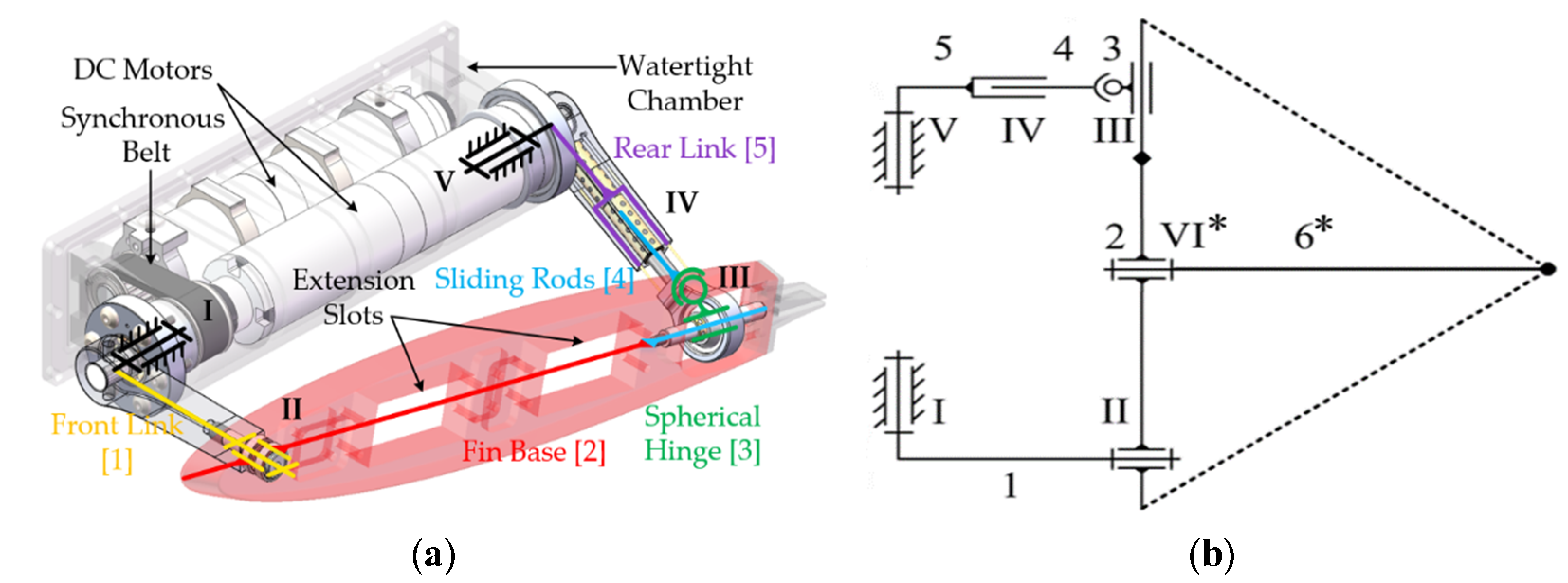
As shown in Figure 2, the mechanism is composed of five structural components connected by five kinetic pairs. Two reciprocating DC motors are parallel installed in a watertight chamber that is mounted to the main body of the robot fish. A synchronous belt-pulley pair is adopted to ensure that the two output shafts pointing in the opposed directions are coaxial. The front 1 and rear link 5 are respectively driven by the revolute pair I and V, which also represent the two motor shafts. The fin base 2 is connected to the front link 1 through the revolute pair II, which consists of double ball bearings to enhance supporting rigidity. A sliding rod with a spherical hinge 3 bushing on it makes up a special pair III that is a compact combination of spherical and cylindrical pair. Since this rod is coincidently fixed on the symmetrical axis of the fin base 2, they can be considered as a whole part. Another sliding rod 4 links up the spherical hinge 3 and rear link 5 to make up another cylindrical pair IV.
The above components and pairs make up a spatial parallel mechanism with 2-DOF. With proper control of the two motors, it can realize the composite locomotion near the fin root and independently control the flapping and pitching angle of fin base 2. In addition to the basic degrees of freedom, optional accessories can also be added, introducing extra DOFs. For example, a standard servo defined as revolute pair VI* can be install to the extension slots on the fin base 2 to adjust the pitching angle near the fin tip through a flexible beam 6*, with the hope that it can better control the fin deformation like the original creatures do to achieve better biomimetic similarity.
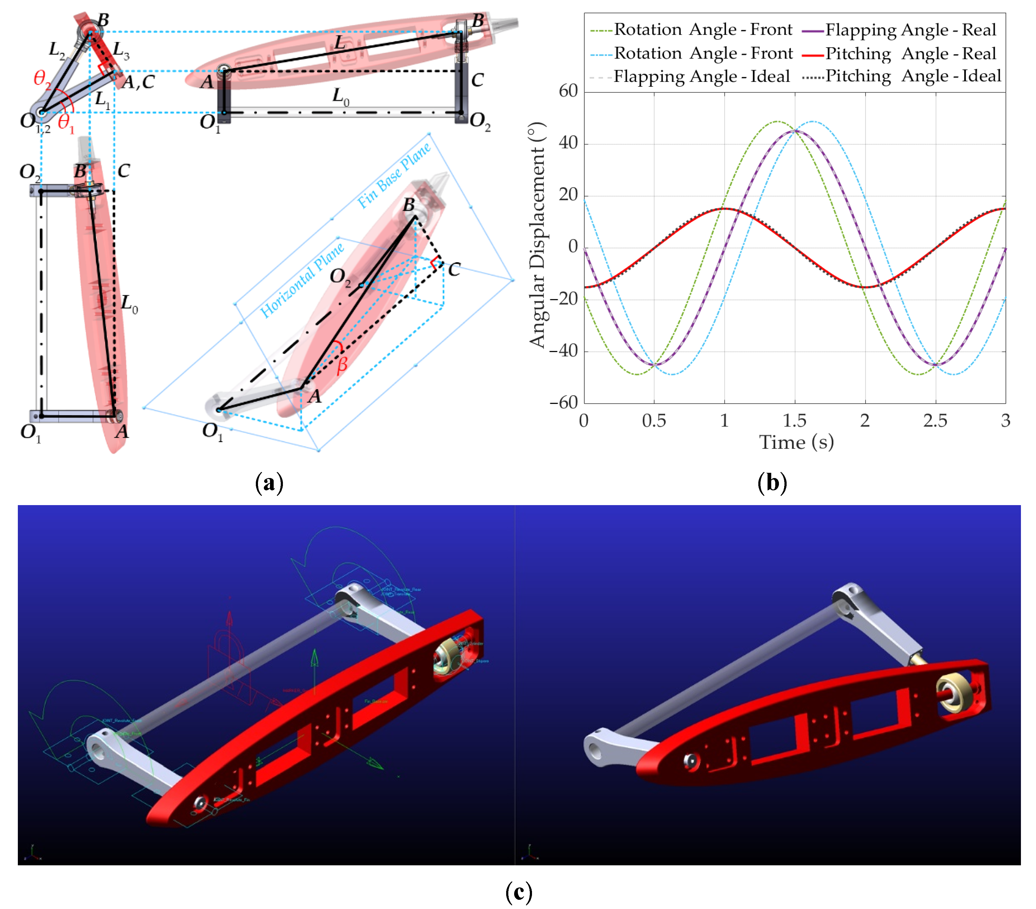
For the purpose of describing the geometric relationship of the components more clearly, the original mechanism shown in Figure 2 can be simplified as a schematic wireframe shown in Figure 3a. The rotation axis of revolute pair I and II is represented as O1O2, which is also coincident with the fin root axis. O1A, O2B and AB represent the front link, the rear link and the fin base, respectively. The composite component of the spherical hinge and sliding rods is simplified into a single point B. C is an imaginary point on the trajectory of point B, where O1A//O2C and O1O2//AC respectively define L, L0, L1, L2 and L3 as the length of line AB, AC, O1A, O2B and BC. θ1 and θ2 respectively represent the angle between O1A, O2B and the horizontal plane (xOy), while β is the angle between AB and AC, which also represents the pitching angle on the fin base plane, which is always perpendicular to O1A. If θ1 = θ2, point B coincides with point C and L = L0, L1 = L2, L3 = 0, whenever θ1 ≠ θ2, L > L0, L1 > L2, L3 > 0. Therefore, the two simplified sliding rods will automatically compensate the length change of O2B and AB if there is a difference between the rotating angle θ1 and θ2 in order to create the pitching angle β, which is the primary idea behind the development of this mechanism.
Based on the geometrical analysis, the pitching angle of fin base can be calculated as
and the flapping angle of the fin base is defined as the average of θ1 and θ2, that is,
The length changes of L and L2 are also needed to design the moving range of the sliding rods, thus calculated as follows:
Since the oscillation of the pectoral fin is close to the sinusoidal motion, the rotating angle of the two driving shafts can be described as:
To be consistent with the motion parameter settings in the following sections, the initial phase of θ1 is set to be zero, while the phase difference between θ1 and θ2 is set as φ. The oscillation amplitude Ai and frequency fi of the front and rear link can be set as equal according to ordinary locomotion pattern of the cownose ray, then
Combining Formulas (2), (3) and (7), the actual composite locomotion of the fin base realized by this mechanism can be described as
According to the kinematic model (1), the middle point of the fin base line AB can be considered as the first segment joint linked to the fin root, then the ideal motion formula is derived as follows:
To better illustrate the relationship between the ideal and real motion, the structural size of the mechanism components and an ordinary set of motion parameters are taken as an example, where L0 = 180 mm, L1 = 64 mm, A = 48.5°, φ = −45°, f = 0.5 Hz. The analysis result shown in Figure 3b was calculated by Matlab R2020b (The MathWorks, Inc., Natick, MA, USA) and same result was also achieved using Adams 2018 (MSC Software Corporation, Newport Beach, CA, USA), proving the consistency between mathematics and simulation. As can be seen from the plotted curves, the real motion follows the sinusoidal pattern just like the ideal one, since the flapping angle αreal precisely matches with αideal and the trajectory of the pitching angle βreal also closely approaches to the perfect sin wave of βideal. The maximum flapping angle is 45°, slightly smaller than the rotating amplitude A, while the max pitching angle is 15°, similar with the real fish. Greater angle values can still be achieved in violent working conditions, but the current parameter setting has been proved adequate for effective propelling. With the accurate motion achieved by this mechanism, abundant actuating power will be generated by the high-torque motors in a concentrated area near the fin root and transferred to the whole fin surface in the sinusoidal waveform to propel the robot fish.
2.3. Design and Fabrication of the Bionic Pectoral Fins
Apart from the bionic propelling mechanism as the fin base, effective propelling also requires properly designed bionic pectoral fin modules to efficiently interact with the hydrodynamic environment. Three different kinds of fin modules were designed and fabricated to perform comparative experiments on the same robot fish platform.
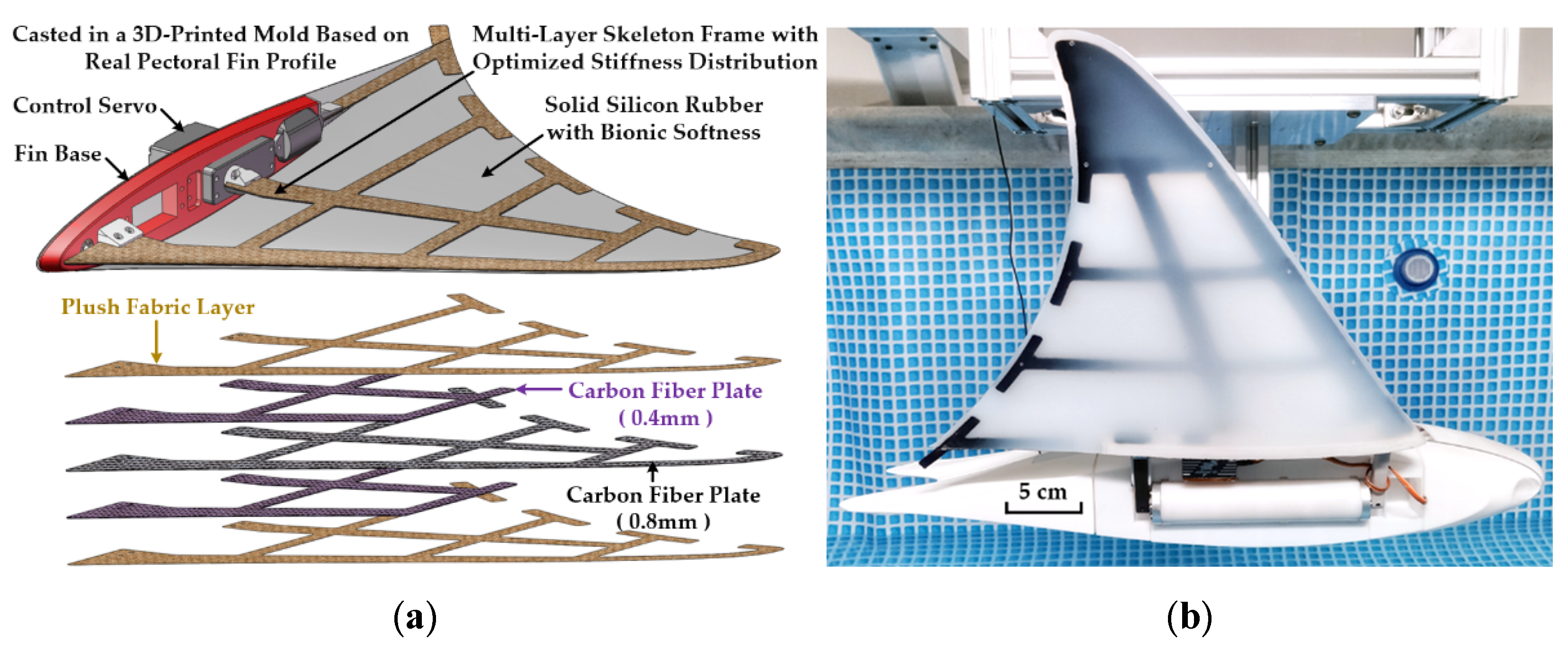
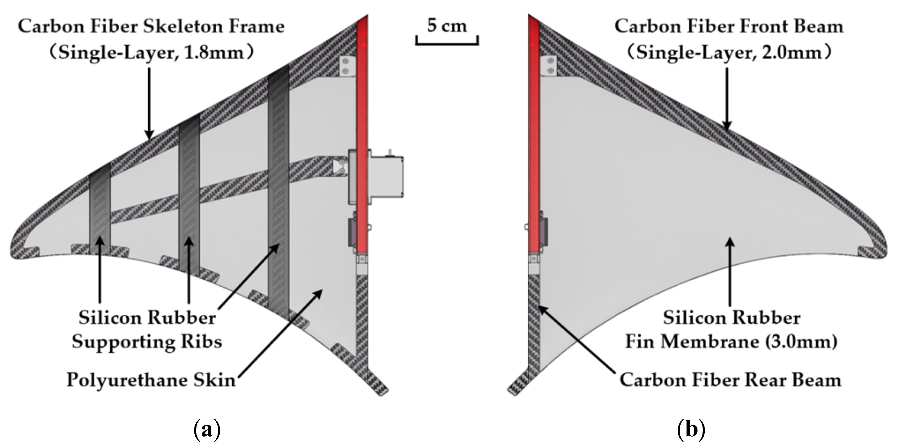
The first kind was constructed with molded PDMS as the basic material to mimic the streamlined 3D profile of the real fin and the bionic softness of its organic tissues. A flexible skeleton frame made of carbon fiber and epoxy resin was placed on the symmetrical plane of the pectoral fin as reinforcement of the soft rubber material. This skeleton frame was designed to mimic the stiffness distribution of the fin cartilages network, which is relatively more rigid at the fin root and leading edge and more flexible near the fin tip and trailing edge [31]. Two different plate thicknesses of 0.4 mm and 0.8 mm were adopted, creating a multi-layer sandwich structure to optimize the stiffness distribution of the skeleton beams further, which differs our method from the traditional single thickness design of the fin skeleton used by previous research [20,21,25,26,27,28,29]. The skeleton frame was also covered with plush fabrics on both sides since the epoxy surface is too smooth for PDMS material to attach. Like the connective tissue between bones and muscles, these fabric layers can ensure that the relatively rigid carbon fiber plate and the softer silicon rubber are tightly bounded. Every layer in this sandwich structure was glued together with flexible adhesive and placed in a 3D-printed mold filled with mixed PDMS. Shore hardness of this silicon rubber material is 5A after solidification, very close to the organic tissues of a real fin. The finished soft bionic fin was then installed on the fin base of the propelling mechanism, whereas the modularized design makes it easy to assemble and replace. The fin structure and prototype photo are shown in Figure 4.
The first kind of fin module has inherited the vantage of the Type-III fin structure (categorized in Section 1) with streamlined 3D profile and bionic softness, while subtly overcame the limitation of the previous design [28,29,30]. It avoids the elastic damping problem by setting one static skeleton frame in the solid rubber surroundings, while still keeping control of the motion wave direction on the fin through concentrated actuation of the dual-DOF propelling mechanism near the fin root. With extra servo installed to the fin base, it can also achieve better deformation control at the fin distal part than the traditional ones that are only capable of passive deformation under hydro force.
The second kind of fin module adopted the structure of Type-II, constructed with a similar flexible skeleton frame and several soft rubber ribs to support a permeable outer skin, as shown in Figure 5a. The geometry and material of the skeleton frame and the supporting ribs are same as the first kind, except that the carbon fiber plate used is of the equivalent thickness of 1.8 mm and the sandwich structure including the plush fabric layer is no longer needed. The outer skin is made of polyurethane cloth, permeable with good flexibility to cover the skeleton and the supporting ribs tightly so as to form the 3D profile of the fin surface without wrinkles.
The third kind is the same as the Type-I fin structure, constructed with only one carbon fiber beam 2 mm thick on the leading edge and a 3 mm soft rubber membrane as the fin surface. The beam uses the same leading edge part cut from the skeleton frame of the above modules, while the fin membrane uses the projection of the 3D geometry and harder rubber material of Shore 20A, shown in Figure 5b. Both kinds of fin modules can be easily assembled and replaced on the fin base, just like the first kind. They will be the comparison groups in the following experiments. For consistency, the span width and chord length of all three fin modules are 300 mm and 298 mm, respectively.
3. Experiment Platform and Settings
3.1. The Robotic Fish Platform
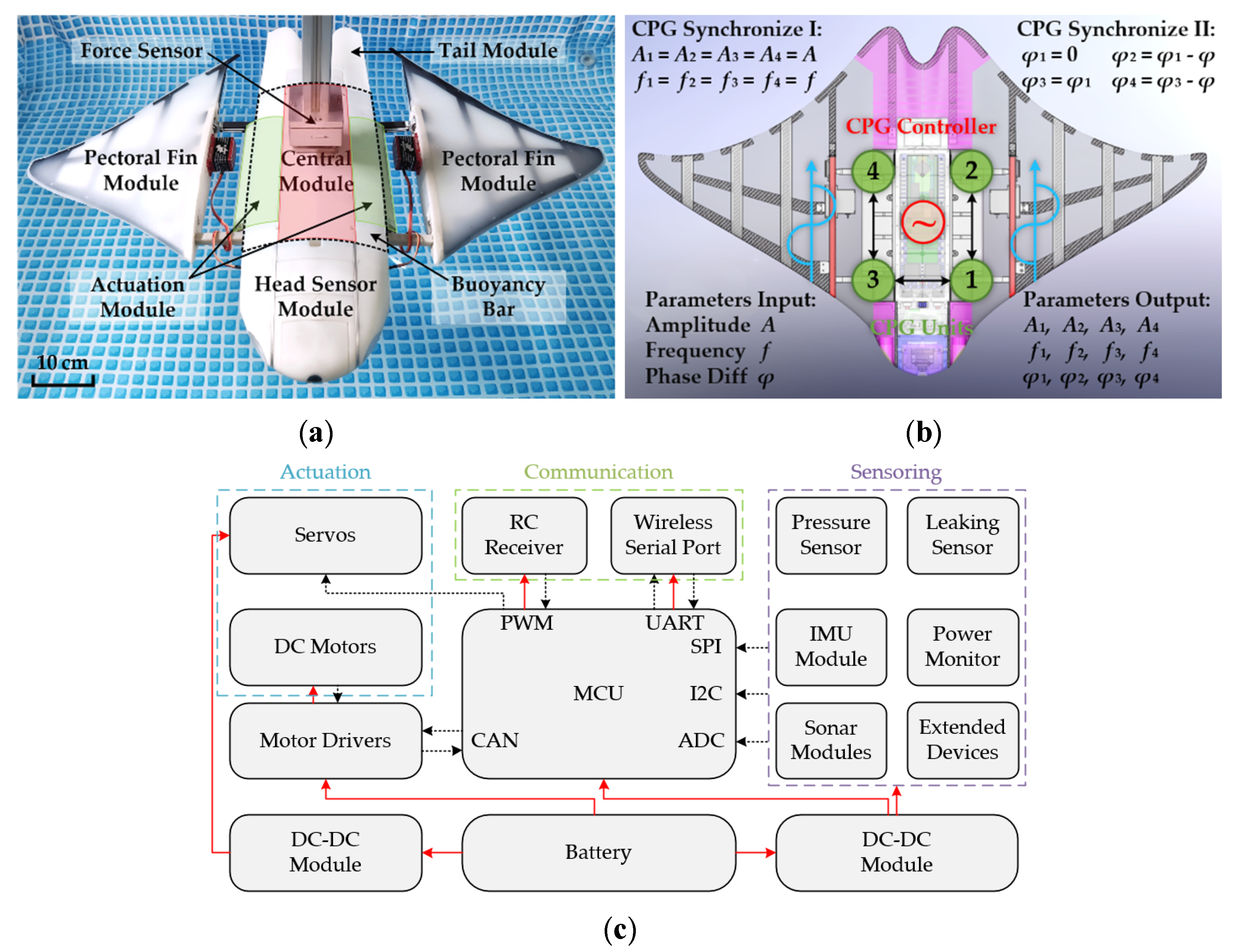
The robotic fish was originally designed to be a general-purpose underwater platform that can carry out different experiments and tasks with many types of payloads. Accordingly, the prototype was divided into multiple function modules that can be assembled or changed with ease. As shown in Figure 6a, the central module (colored in red) is a watertight box located at the center of the fish body, functioning as the main power and control unit. Two actuation modules (colored in green) are connected to the central module on both sides, and each contains two driving motors and links with a bionic pectoral fin module. The fish head module contains multiple sensors like camera and sonars, while the tail module functions as a rudder to adjust the global pitching of the robot fish. Several buoyancy bars (black dashed line) are attached to the upper and lower surface of the central module and actuation modules, adjusting the buoyancy and weight center to keep the fish balanced in the water. The geometry outline of the fish closely resembles the 3D profile of real cownose rays, and most parts that would interact with water, including the pectoral fins, the head and tail module, the buoyancy bars on the fish back and belly, were either 3D-printed directly or cast in a 3D-printed mold, based on the parametric geo model established in our previous research [33], utilizing bionic morphology to achieve better hydrodynamic performance.
The electronic hardware of the control system includes a minimum system board based on STM32F429 as the central control unit, four motor drivers that communicate through CAN bus, a 170 MHz RF module for wireless data transmission underwater, plus some basic sensors such as camera, sonar, pressure and leakage monitor. A 6400 mAh, 25.2 V lithium battery was also integrated with the above devices, capable of powering the robot platform for about 90 min under experimental conditions. Meanwhile, a CPG-based control program was developed to iteratively calculate the motion parameters for different fin actuators, enabling smooth and robust fin motion control with simplified parameters input (amplitude, frequency, and phase difference), illustrated in Figure 6b. Moreover, a schematic of the electronic hardware is illustrated as Figure 6c for better comprehension.
3.2. Experimental Environment and Equipment Setup
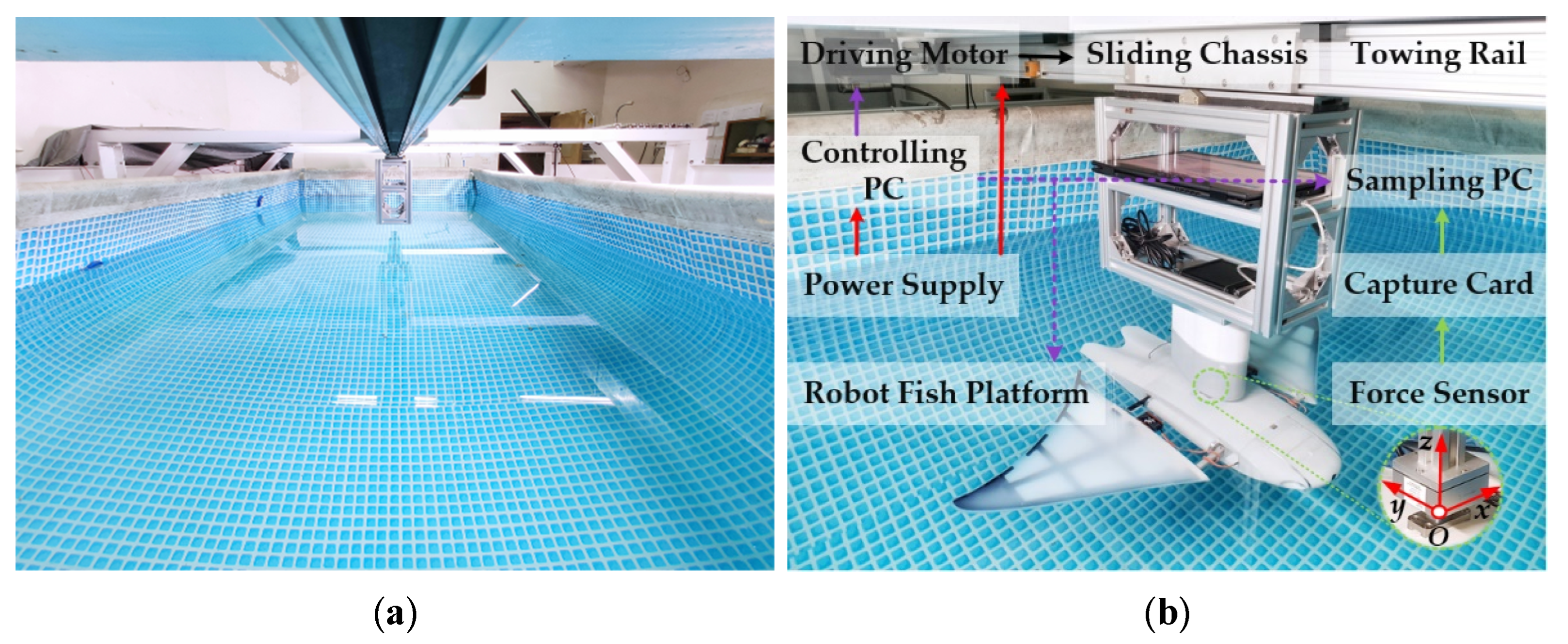
The hydrodynamic experiment was performed in a water pool with dimensions of 4.0 m × 5.5 m × 1.3 m, with a 6-m towing rail mounted on the steel beam above it, as shown in Figure 7a. In this research, the water depth in the pool was set at a maximum level of 1.2 m, and the robot fish platform was placed in the middle of the pool, 2.0 m from the nearest lateral wall and 0.6 m from the bottom, in order to eliminate the interference of reflected waves as much as possible.
A triple-axis force sensor was mounted on the back of the robot fish platform through a flank and linked to the sampling PC through a 4-channel capture card. All the data sampling devices were installed on an aluminum alloy frame that linked with a sliding chassis on the towing rail. Another controlling PC was used to remotely send motion parameters to the robot fish and communicate with the sampling PC, as well as giving commands to the servo motor that drives the sliding chassis at a configurable steady speed. A 220 V power supply was used for the controlling PC and the driving motor only, whereas the experimental platform is self-powered by batteries. Different arrow lines are used in Figure 7b to better illustrate the connections among all the experiment devices. The force sampling dataflow are colored in green, the control signals are in purple, and power lines are marked in red. All the solid lines stand for cable connections, while the dashed lines represent wireless communication.
To comparatively study the hydrodynamic performance of the three different kinds of pectoral fins under different working conditions, the experiments were divided into three test groups, and for each group, and only one parameter was changed at a time. The size and weight of the robot fish platform, as well as all related motion parameters and their value ranges, are shown in Table 1.
4. Results and Discussion
In this section, the experiment results will be illustrated and discussed. The results of the first kind of fin modules, the solid ones with 3D-profile and bionic softness, were categorized as Group 1, while Group 2 and Group 3 correspond to the second and third kinds of fin modules, respectively. The definition of the three test groups remains unchanged for the rest of this paper. For better understanding and reference, a mapping table of the above terminologies is listed as Table 2.
4.1. Instantaneous Thrust and Lift Force
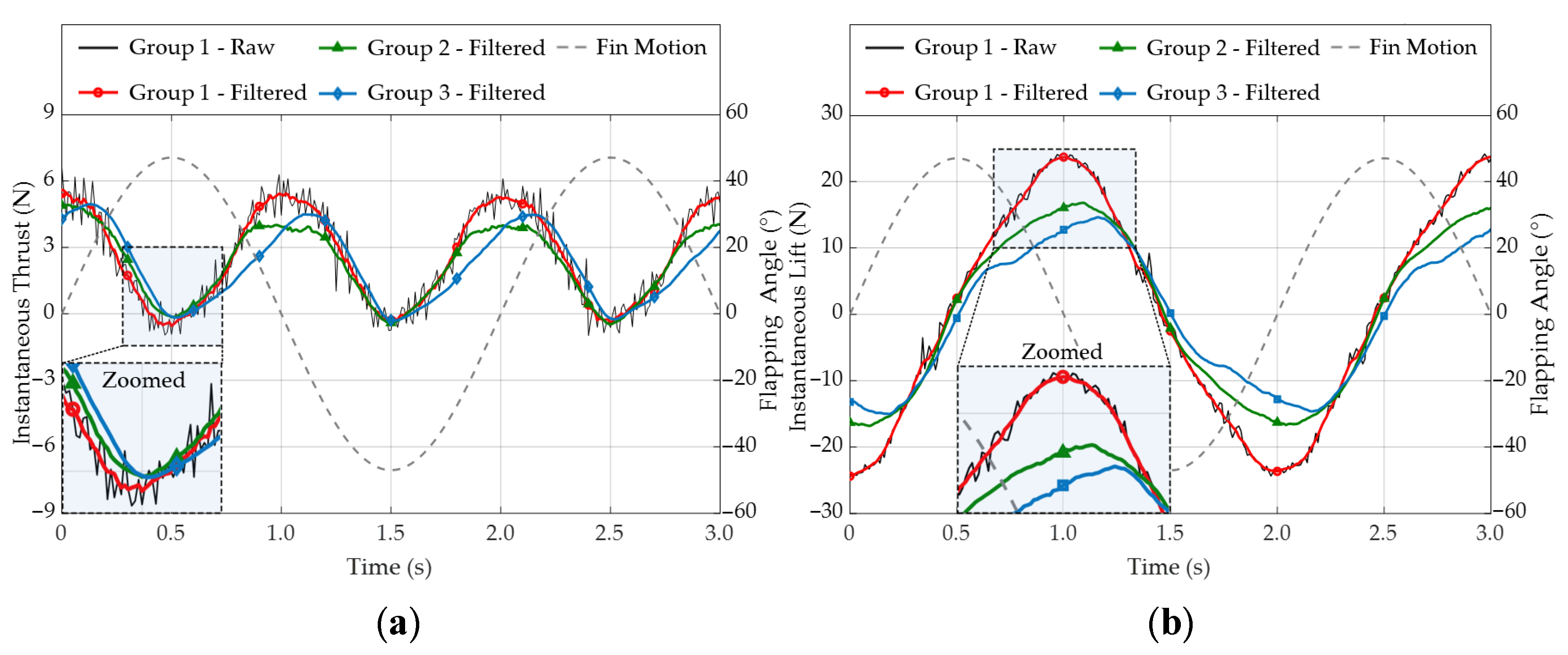
The effective thrust and global lift force produced by the oscillating pectoral fins on the whole robot fish platform were recorded at a sampling frequency of 100 Hz during the experiment. The relationship between the instantaneous thrust/lift waveform and the fin motion curve can be illustrated by the force trajectories of different test groups shown in Figure 8. All data was recorded at the parameter set of A = 45°, f = 0.5 Hz, φ = 30°, V = 0.2 m/s, and filtered to reduce electrical and mechanical noise. The saw-toothed force waves plotted directly from the raw data of Group 1 were added to show the difference, while trajectories of Group 2 and 3 were already smoothed for a clearer view.
As can be seen, both thrust and lift followed periodic waveforms. Compared to the motion curve of flapping angle αreal at the fin base (the grey dashed line), the position of the force peaks and troughs indicates that the maximum thrust and lift (absolute value) were generated simultaneously when the pectoral fin was going through the neutral plane xOy at its max angular velocity, whereas the minimum appeared when the fin was changing direction. The difference is that the thrust was generated in a single direction and there were two positive peaks in one oscillation period, while the lift direction changed along with the flapping direction. So the thrust waves were mostly above zero with twice the flapping frequency f, and the lift force distributed symmetrically like the flapping angle curve, with an equal frequency f and a 1/4 T phase difference. The force trajectories of Group 1 resembled the sinusoidal waveform quite well, while the relatively ill-shaped waveforms of Group 2 and 3 might indicate that some thrust/lift was lost or not properly generated due to the structural or material feature of the fin. More comparative results will be discussed in the following sections.
4.2. Average Thrust and Propulsion Performance
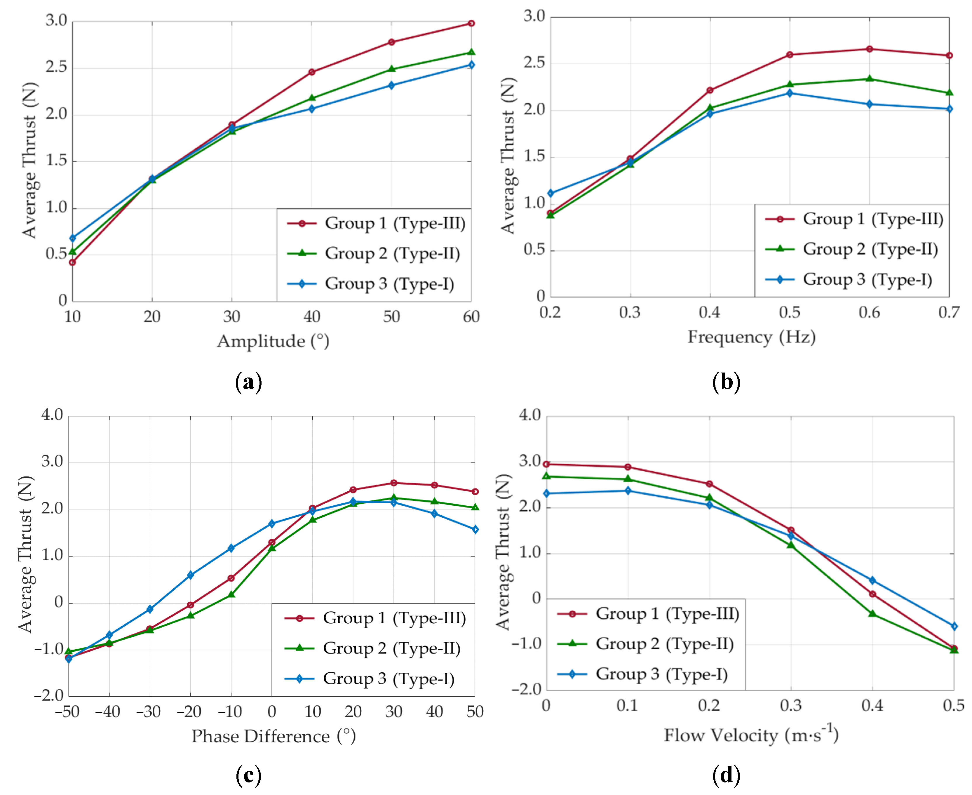
Compared to the instantaneous thrust shown in Figure 8a, the average thrust can represent the propulsion performance of different fin modules more intuitively. In this research, data from five consecutive stable oscillating periods were used to calculate the average thrust, with the purpose of avoiding episodic measuring errors to ensure the reliability of the calculated values. Noticeable differences in the average thrust were observed when altering the combination of the parameter set of A, f, φ, and V, which will be respectively discussed as follows.
Figure 9a shows the relationship between the average thrust and the flapping amplitude. Other parameters were fixed as f = 0.5 Hz, φ = 30°, V = 0.2 m/s. The value curves of all three test groups climbed with the increase of amplitude. The average thrust of Group 1 was at the bottom when A = 10°, but rapidly exceeded the other two after 30°, finally reaching a maximum of 2.98 N at 60°, 11.6%, and 16.4% higher than Group 2 and 3, respectively. The growth rates of Group 1 and 2 started to drop after 30°, from a maximum of 0.089 N/° at 20° to 0.018 N/° at 60°, while Group 3 still increased about linearly, keeping a relatively lower rate of 0.023 N/°. The above phenomenon indicates that the fin modules of Group 1 were more suitable for high amplitude conditions, while Group 3 had more steady performance at a wider range due to better elastic compliance of the fin membrane. The 3D fin profile surely had advantage over 2D at a regular amplitude range of 40°–60°, and the difference between Group 1 and 2 was possibly because that solid rubber fin could better preserve the streamlined profile dynamically, while the flexible hollow skin would be crashed into the supporting ribs under water pressure, jeopardizing its original low-drag profile. Moreover, the solid rubber surface could better interact with the surrounding water, while the permeable skin would cause considerable power loss since part of the water passed through the porous fabric, instead of transferring more kinetic energy to the fin.
Figure 9b shows the relationship between the average thrust and the oscillating frequency. Other parameters were fixed as A = 45°, φ = 30°, V = 0.2 m/s. The thrust curves of Group 1 and 2 climbed with the increase of frequency before 0.6 Hz and then started to drop, while the inflexion point of Group 3 came earlier at about 0.5 Hz. All three groups increased rapidly before 0.4 Hz, when the average growth rate of Group 1 to 3 was 6.57 N/Hz, 5.77 N/Hz, and 4.28 N/Hz, respectively, and then dropped to 2.21 N/Hz, 1.56 N/Hz, and 0.51 N/Hz between 0.4–0.6 Hz, respectively. The thrust of Group 3 was 24.3% higher at 0.2 Hz than the rest, but fell 22.23% and 11.54% lower than Group 1 and 2 at 0.6 Hz, respectively. The above results show that higher frequency did not ensure higher thrust, and the best frequency for different groups was not the same. This might be related with the natural frequency of the fin modules, since they were of different structures and materials. Previous research [34] revealed that the thrust and efficiency of a flexible heaving wing would be enhanced when its natural frequency came close to the forcing frequency. The optimal frequency of Group 3 was lower, and it performed much better than Group 1 and 2 under the low frequency of 0.2 Hz. This might indicate that the 2D fin membrane is more suitable for low-frequency cruising scenarios for the fish. The difference between Group 1 and 2 was no more than 0.07 N under 0.3 Hz, but with the increasing flapping frequency, the advantage of solid soft rubber over hollow flexible skin started to show. The maximum thrust of 2.65 N occurred at 0.6 Hz for Group 1, 13.7% higher than Group 2, yet still 12.4% lower than the max thrust achieved under max amplitude, indicating that promoting thrust force through higher amplitude is a better option than using higher frequency. Figure 9c shows the relationship between average thrust and the phase difference of the flapping angle. Other parameters were fixed as A = 45°, f = 0.5 Hz, V = 0.2 m/s. Similar to the “thrust-frequency” curves, the average thrust of all three groups first increased and then started to drop down after reaching a certain phase difference. The max thrust was achieved when φ ≈ 30° for Group 1 and 2, while that of Group 3 came earlier at φ ≈ 20°. For Group 1 and 2, the difference was less than 7.1% between the max thrust and the neighboring values in the range of 20°~50°, but for Group 3, the thrust force decreased rapidly after 30° at a rate of −0.03 N/°, and even fell 7.51% lower than the force value at 0° (1.70 N). The values of Group 1 and 2 dropped at a similar average rate of −0.075 N/° from 10° to −10° when the chord-wise motion wave was changing direction, faster than in other ranges, whereas the decreasing curve of Group 3 was relatively smoother under the same circumstance, at the average rate of only 0.04 N/°. All three groups could still generate positive thrust even with a negative phase difference. While the average thrust of Group 1 and 2 dropped below 0 at around −10°~−20°, Group 3 could keep the positive thrust until −30°. The phenomenon above indicates that a positive phase difference was necessary for bionic pectoral fins to generate higher forward thrust, especially for the ones with 3D profiles. Although there was an optimum value to choose from, the phase difference actually had less influence on thrust generation than amplitude and frequency in a certain range. Nevertheless, the case was quite different for fins with the 2D membrane (Group 3). It could generate 45.18% higher thrust than the 3D ones at zero phase difference, and keep the forward propulsion with a negative phase difference, probably thanks to its fin structure that the single rigid beam at the front edge makes the soft fin surface behind it easier to generate positively transferred motion waves and thrust, but also harder to wave oppositely, even when the fin base had already been pitching backwards. When oscillating under a large phase difference, no matter positive or negative, the pitching angle of the passively deformed fin surface would reach a stalling threshold similar to the airfoils, greatly increasing drag and reducing lift, whereas the 3D fins with the streamlined profile would only come to this problem with a much higher angle of attack. Accordingly, the 2D fins modules (Group 3, Type-I) performed better with low or no proactive pitching angle, while the 3D fins could achieve higher performance than 2D ones at a proper range of phase difference, as well as utilizing it to proactively control the thrust on either side to alter the propelling direction.
Figure 9d shows the relationship between average thrust and flow velocity (towing speed). Other parameters were fixed as A = 45°, f = 0.5 Hz, φ = 30°. The thrust of Group 1 was always higher than Group 2 at approximately 10.3%. Both of them were relatively steady in the range of 0~0.1 m/s, then decreased rapidly after 0.2 m/s and dropped below 0 at about 0.37 m/s and 4.05 m/s, respectively. The behavior of Group 3 was similar, but its dropping slope was smaller than the former two groups and it reached the zero line later at about 4.5 m/s. The results above indicate that the 2D fins had lower drag at a higher speed, perhaps more suitable for high-speed cruising scenarios than the 3D ones, possibly because the characteristic area of the 2D membrane is much smaller than the 3D profile, and the better elastic compliance in high-speed water flow makes the passively formed angle of attack more suitable for thrust generation. The difference in the performance of Group 3 under high-speed and low-speed conditions was quite curious, which requires further theoretical analysis in the future. Meanwhile, Group 1 still generated higher thrust at 0~0.3 m/s, which would offer the robot fish better acceleration and maneuverability performance than the rest two. The differences among the three kinds of bionic fin modules in propelling performance, as well as their pros and cons will be concluded in the final section.
5. Conclusions and Future Work
In this paper, a new bionic pectoral fin module used on a ray-inspired robotic fish was presented, together with a novel bionic propelling mechanism as the actuating base. Hydrodynamic experiment was carried out to comparatively study the differences in propelling performance between the new bionic fin module and the traditional designs under various working conditions, with the purpose of better understanding the MPF propulsion mode and finding optimal solutions for different fin types based on the same evaluation platform.
With the guidance of the pectoral fin kinematic model, the novel spatial parallel mechanism was designed. Motion analysis proved that it was capable of reproducing the composite motion pattern of the real creature and controlling the flapping and pitching angle near the fin root with its two basic degrees of freedom. Extra DOFs could also be added to better control the surface deformation at the fin distal part. Combined with this novel mechanism base, a pectoral fin module with high-fidelity 3D profile and bionic softness, which can solve the contradiction between controllability and actuating efficiency, was proposed as the upgrade of our previously categorized Type-III fins. A pair of this new kind of fin modules, as well as two other traditional kinds (Type-I & II), were fabricated and tested on our robotic fish platform in a towing water pool with a 3-axis force sensor. The variations in the thrust and lift force under four different parameter settings (A, f, φ, and V) were collected and analyzed. The following conclusions could be drawn from the results of the hydrodynamic experiment:
- The average thrust grew constantly with the increased flapping amplitude and dropped continuously with the increased flow velocity, while there were optimal value ranges of frequency and phase difference to achieve maximum average thrust;
- The 3D-profiled fins had advantages over the 2D ones in an amplitude range of 40°~60° at a regular frequency of 0.5 Hz, while the 2D-membrane fins were more suitable for medium to high-speed cruising scenarios with relatively smaller phase difference and lower frequency;
- The alterable phase difference and pitching angle achieved by the novel propelling mechanism offered both the 3D and the 2D fins an increased thrust generation as well as proactive direction control of the motion waves, especially for the 3D ones;
- Fin modules of Group 1 outperformed those of Group 2 in most of the cases while their thrust features (curve trends) were quite similar, indicating that the newly proposed bionic soft fins would be an upgraded substitute for the traditional skin-structured fins.
In the future, theoretical analysis and hydrodynamic modeling of the bionic pectoral fin will be conducted to further study the principles behind the current experiment results and better understand MPF bionic propulsion. Experiments with the particle image velocimetry device (PIV) will be carried out to observe the flow field and vortex structure produced by the oscillating pectoral fins, which might reveal the reasons behind some unexplained curious phenomena. Additionally, autonomous swimming control with multi-sensor fusion algorithm will also be tested on the modularized robot fish platform.
Author Contributions
Supervision—L.C., S.B. and Y.C.; writing—original draft preparation, L.C.; writing—review and editing, H.Q.; funding acquisition, Y.C. All authors have read and agreed to the published version of the manuscript.
Funding
This research was funded by the National Key Research and Development Program, grant number 2020YFB1313200; Fundamental Research Funds for the Central Universities, grant number YWF-22-L-913.
Institutional Review Board Statement
Not applicable.
Informed Consent Statement
Not applicable.
Data Availability Statement
Not applicable.
Conflicts of Interest
The authors declare no conflict of interest.
References
- Lee, M.-F.R.; Chen, Y.-C. An Innovative Pose Control Mechanism for a Small Rudderless Underwater Vehicle. Machines 2022, 10, 352. [Google Scholar] [CrossRef]
- Yu, D.; Zhu, C.; Zhang, M.; Liu, X. Experimental Study on Multi-Domain Fault Features of AUV with Weak Thruster Fault. Machines 2022, 10, 236. [Google Scholar] [CrossRef]
- Sharma, S.D.; Mani, K.; Arakeri, V.H. Cavitation noise studies on marine propellers. J. Sound Vib. 1990, 138, 255–283. [Google Scholar] [CrossRef]
- Bandyopadhyay, P.R. Trends in biorobotic autonomous undersea vehicles. IEEE J. Ocean. Eng. 2005, 30, 109–139. [Google Scholar] [CrossRef]
- Song, Z.; Fu, Z.; Romano, D.; Dario, P.; Kang, R. A Novel Fish-Inspired Robot with a Double-Cam Mechanism. Machines 2022, 10, 190. [Google Scholar] [CrossRef]
- Xing, H.; Guo, S.; Shi, L.; Hou, X.; Liu, Y.; Liu, H.; Hu, Y.; Xia, D.; Li, Z. A novel small-scale turtle-inspired amphibious spherical robot. In Proceedings of the 2019 IEEE/RSJ International Conference on Intelligent Robots and Systems (IROS), Macau, China, 3–8 November 2019; pp. 1702–1707. [Google Scholar]
- Katzschmann, R.K.; DelPreto, J.; MacCurdy, R.; Rus, D. Exploration of underwater life with an acoustically controlled soft robotic fish. Sci. Robot. 2018, 3, eaar3449. [Google Scholar] [CrossRef] [Green Version]
- Lindsey, C.C. Form, Function, and Locomotory Habits in Fish. Fish Biol. 1978, 7, 1–100. [Google Scholar] [CrossRef]
- Yu, J.Z.; Chen, E.K.; WANG, S.; Tan, M. Research evolution and analysis of biomimetic robot fish. Control Theory Appl. 2003, 20, 485–491. [Google Scholar]
- Ozmen Koca, G.; Bal, C.; Korkmaz, D.; Bingol, M.C.; Ay, M.; Akpolat, Z.H.; Yetkin, S. Three-dimensional modeling of a robotic fish based on real carp locomotion. Appl. Sci. 2018, 8, 180. [Google Scholar] [CrossRef] [Green Version]
- Ay, M.; Korkmaz, D.; Ozmen Koca, G.; Bal, C.; Akpolat, Z.H.; Bingol, M.C. Mechatronic design and manufacturing of the intelligent robotic fish for bio-inspired swimming modes. Electronics 2018, 7, 118. [Google Scholar] [CrossRef] [Green Version]
- Blake, R.W. Fish functional design and swimming performance. J. Fish Biol. 2004, 65, 1193–1222. [Google Scholar] [CrossRef]
- Triantafyllou, M.S.; Hover, F.S.; Techet, A.H.; Yue, D.K.P. Review of hydrodynamic scaling laws in aquatic locomotion and fishlike swimming. Appl. Mech. Rev. 2005, 58, 226–237. [Google Scholar] [CrossRef] [Green Version]
- Arauz, R.; Chávez, E.J.; Hoyos-Padilla, E.M.; Marshall, A.D. First record of the reef manta ray, Mobula alfredi, from the eastern Pacific. Mar. Biodivers. Rec. 2019, 12, 3. [Google Scholar] [CrossRef]
- Fish, F.E.; Schreiber, C.M.; Moored, K.W.; Liu, G.; Dong, H.; Bart-Smith, H. Hydrodynamic performance of aquatic flapping: Efficiency of underwater flight in the manta. Aerospace 2016, 3, 20. [Google Scholar] [CrossRef] [Green Version]
- Rosenberger, L.J. Pectoral fin locomotion in batoid fishes: Undulation versus oscillation. J. Exp. Biol 2001, 204, 379–394. [Google Scholar] [CrossRef] [PubMed]
- Schaefer, J.T.; Summers, A.P. Batoid wing skeletal structure: Novel morphologies, mechanical implications, and phylogenetic patterns. J. Morphol. 2005, 264, 298–313. [Google Scholar] [CrossRef]
- Meng, Y.; Wu, Z.; Dong, H.; Wang, J.; Yu, J. Toward a novel robotic manta with unique pectoral fins. IEEE Trans. Syst. Man Cybern. Syst. 2020, 52, 1663–1673. [Google Scholar] [CrossRef]
- Zhou, C.; Low, K.H. Design and locomotion control of a biomimetic underwater vehicle with fin propulsion. IEEE/ASME Trans. Mechatron. 2011, 17, 25–35. [Google Scholar] [CrossRef]
- Cai, Y.; Bi, S.; Zhang, L. Design and implication of a bionic pectoral fin imitating cow-nosed ray. In Proceedings of the 2010 IEEE/RSJ International Conference on Intelligent Robots and Systems (IROS), Taipei, Taiwan, 18–22 October 2010; pp. 3525–3529. [Google Scholar]
- Chew, C.M.; Lim, Q.Y.; Yeo, K.S. Development of propulsion mechanism for Robot Manta Ray. In Proceedings of the 2015 IEEE International Conference on Robotics and Biomimetics, Zhuhai, China, 6–9 December 2015; pp. 1918–1923. [Google Scholar]
- Wang, Z.; Hang, G.; Li, J. Shape memory alloy wire actuated flexible biomimetic fin for quiet underwater propulsion. J. Mech. Eng. 2009, 45, 126–131. [Google Scholar] [CrossRef]
- Li, G.; Chen, X.; Zhou, F.; Liang, Y.; Xiao, Y.; Cao, X.; Zhang, Z.; Zhang, M.; Wu, B.; Yin, S.; et al. Self-powered soft robot in the Mariana Trench. Nature 2021, 591, 66–71. [Google Scholar] [CrossRef]
- Festo Aqua_Ray. Available online: https://www.festo.com.cn/cn/zh/e/about-festo/research-and-development/bionic-learning-network/highlights-from-2006-to-2009/aqua-ray-id_33860/ (accessed on 14 February 2022).
- Cai, Y.; Bi, S.; Low, K.H.; Zhang, L.; Zong, G. Posture analysis and application of a bionic pectoral foil. In Proceedings of the 2011 IEEE International Conference on Robotics and Biomimetics, Karon Beach, Thailand, 7–11 December 2011; pp. 1783–1788. [Google Scholar]
- Ma, H.; Cai, Y.; Wang, Y.; Bi, S.; Gong, Z. A biomimetic cownose ray robot fish with oscillating and chordwise twisting flexible pectoral fins. Ind. Robot. Int. J 2015, 42, 214–221. [Google Scholar] [CrossRef]
- Xing, C.; Cao, Y.; Cao, Y.; Pan, G.; Huang, Q. Asymmetrical Oscillating Morphology Hydrodynamic Performance of a Novel Bionic Pectoral Fin. J. Mar. Sci. Eng. 2022, 10, 289. [Google Scholar] [CrossRef]
- Cai, Y.; Bi, S.; Zheng, L. Design and experiments of a robotic fish imitating cow-nosed ray. J. Bionic Eng. 2010, 7, 120–126. [Google Scholar] [CrossRef]
- Cai, Y.; Chen, L.; Bi, S.; Li, G.; Zhang, H. Bionic Flapping Pectoral Fin with Controllable Spatial Deformation. J. Bionic Eng. 2019, 16, 916–930. [Google Scholar] [CrossRef]
- Fish, F.E.; Dong, H.; Zhu, J.J.; Bart-Smith, H. Kinematics and hydrodynamics of mobuliform swimming: Oscillatory winged propulsion by large pelagic batoids. Mar. Technol. Soc. J. 2017, 51, 35–47. [Google Scholar] [CrossRef]
- Russo, R.S.; Blemker, S.S.; Fish, F.E.; Bart-Smith, H. Biomechanical model of batoid (skates and rays) pectoral fins predicts the influence of skeletal structure on fin kinematics: Implications for bio-inspired design. Bioinspir. Biomim. 2015, 10, 046002. [Google Scholar] [CrossRef] [Green Version]
- Cao, Y. Applying CPG to Study Manta Robofish. Ph.D. Thesis, School of Mechanical Engineering and Automation, Beihang University, Beijing, China, 2015. [Google Scholar]
- Chen, L.; Bi, S.; Cai, Y.; Cao, Y.; Pan, G. Design and Experimental Research on a Bionic Robot Fish with Tri-Dimensional Soft Pectoral Fins Inspired by Cownose Ray. J. Mar. Sci. Eng. 2022, 10, 537. [Google Scholar] [CrossRef]
- Michelin, S.; Llewellyn Smith, S.G. Resonance and propulsion performance of a heaving flexible wing. Phys. Fluids 2009, 21, 071902. [Google Scholar] [CrossRef] [Green Version]
Figure 1.
Kinematic model. (a) Definition of the pectoral fin coordinate system; (b) Discretization and motion decoupling of the pectoral fin.
Figure 1.
Kinematic model. (a) Definition of the pectoral fin coordinate system; (b) Discretization and motion decoupling of the pectoral fin.

Figure 2.
Dual-DOF bionic propelling mechanism. (a) Structural assembly of the spatial parallel mechanism; (b) Planar scheme of the mechanism.
Figure 2.
Dual-DOF bionic propelling mechanism. (a) Structural assembly of the spatial parallel mechanism; (b) Planar scheme of the mechanism.

Figure 3.
Kinematic analysis of the mechanism. (a) Geometric relationship of the fin components; (b) Comparison between the real motion trajectory and the ideal pattern; (c) Motion simulation environment of ADAMS.
Figure 3.
Kinematic analysis of the mechanism. (a) Geometric relationship of the fin components; (b) Comparison between the real motion trajectory and the ideal pattern; (c) Motion simulation environment of ADAMS.

Figure 4.
The pectoral fin module with 3D profile and bionic softness. (a) Sandwich structure of the fin skeleton frame; (b) Photo of the finished bionic soft fin module.
Figure 4.
The pectoral fin module with 3D profile and bionic softness. (a) Sandwich structure of the fin skeleton frame; (b) Photo of the finished bionic soft fin module.

Figure 5.
The pectoral fin modules with traditional design. (a) Structure of the Type-II fin module; (b) Structure of the Type-I fin module.
Figure 5.
The pectoral fin modules with traditional design. (a) Structure of the Type-II fin module; (b) Structure of the Type-I fin module.

Figure 6.
The ray-inspired robotic fish platform. (a) Photo of the modularized prototype; (b) The units and motion parameters of the CPG control method; (c) Schematic of the electronic hardware.
Figure 6.
The ray-inspired robotic fish platform. (a) Photo of the modularized prototype; (b) The units and motion parameters of the CPG control method; (c) Schematic of the electronic hardware.

Figure 7.
Environment and settings of the hydrodynamic experiments. (a) The experimental water pool with towing rail; (b) Configuration of the motion control and data collecting devices.
Figure 7.
Environment and settings of the hydrodynamic experiments. (a) The experimental water pool with towing rail; (b) Configuration of the motion control and data collecting devices.

Figure 8.
Instantaneous thrust and lift of different test groups. (a) Trajectories comparison of the instantaneous thrust; (b) Trajectories comparison of instantaneous lift.
Figure 8.
Instantaneous thrust and lift of different test groups. (a) Trajectories comparison of the instantaneous thrust; (b) Trajectories comparison of instantaneous lift.

Figure 9.
Average thrust comparison among different fin groups. (a) The influence of amplitude on average thrust; (b) The influence of frequency on average thrust; (c) The influence of phase difference on average thrust; (d) The influence of flow velocity on average thrust.
Figure 9.
Average thrust comparison among different fin groups. (a) The influence of amplitude on average thrust; (b) The influence of frequency on average thrust; (c) The influence of phase difference on average thrust; (d) The influence of flow velocity on average thrust.


Table 1.
Robot Platform and Motion Parameter Information of the Hydrodynamic Experiment.
| Platform Diameter | Platform Weight | ||
|---|---|---|---|
| L560 mm × W890 mm × H110 mm | 6.2 kg (Fin Type-I), 8.0 kg (Fin Type-II & III) | ||
| Motion Parameter | Notation | Unit | Value Range |
| Amplitude | A | Degree (°) | 10~60, step 10 |
| Frequency | f | Hz | 0.2~0.7, step 0.1 |
| Phase Difference | φ | Degree (°) | −50~50, step 10 |
| Flow Velocity (Towing Speed) | V | m/s | 0~0.5, step 0.1 |
Table 2.
Mapping Table of the Experiment Group Numbers and Fin Structure Types.
| Group Number | Fin Structure Type | Features of the Structure |
|---|---|---|
| Group 1 | Type-III (Upgraded) | 3D Profile, Solid Structure, Bionic Softness |
| Group 2 | Type-II (Traditional) | 3D Profile, Hollow Structure, Flexible Skin |
| Group 3 | Type-I (Traditional) | 2D Profile, Soft Membrane, Rigid Leading Edge |
Publisher’s Note: MDPI stays neutral with regard to jurisdictional claims in published maps and institutional affiliations. |
© 2022 by the authors. Licensee MDPI, Basel, Switzerland. This article is an open access article distributed under the terms and conditions of the Creative Commons Attribution (CC BY) license (https://creativecommons.org/licenses/by/4.0/).
Share and Cite
MDPI and ACS Style
Chen, L.; Bi, S.; Cai, Y.; Qiu, H. Design and Hydrodynamic Experiment Research on Novel Biomimetic Pectoral Fins of a Ray-Inspired Robotic Fish. Machines 2022, 10, 606. https://doi.org/10.3390/machines10080606
AMA Style
Chen L, Bi S, Cai Y, Qiu H. Design and Hydrodynamic Experiment Research on Novel Biomimetic Pectoral Fins of a Ray-Inspired Robotic Fish. Machines. 2022; 10(8):606. https://doi.org/10.3390/machines10080606
Chicago/Turabian StyleChen, Lingkun, Shusheng Bi, Yueri Cai, and Hongcheng Qiu. 2022. "Design and Hydrodynamic Experiment Research on Novel Biomimetic Pectoral Fins of a Ray-Inspired Robotic Fish" Machines 10, no. 8: 606. https://doi.org/10.3390/machines10080606
Note that from the first issue of 2016, this journal uses article numbers instead of page numbers. See further details here.