
Influence of Fit Clearance and Tightening Torque on Contact Characteristics of Spindle–Grinding Wheel Flange Interface


Key Laboratory of Education Ministry for Modern Design and Rotor-Bearing System, Xi’an Jiaotong University, Xi’an 710049, China
*
Author to whom correspondence should be addressed.
Machines 2022, 10(5), 298; https://doi.org/10.3390/machines10050298
Submission received: 23 March 2022
/
Revised: 15 April 2022
/
Accepted: 21 April 2022
/
Published: 22 April 2022
(This article belongs to the Special Issue Rolling Bearing and Rotor System Modeling and Simulation, Monitoring and Control, and Performance Diagnosis)
Abstract
:The spindle and grinding wheel flange (GWF) adopt double positioning of a tapered surface and end face. Due to the processing quality, the contact state of the spindle–GWF interface cannot be determined accurately. Based on the theory of finite element and the Yoshimura integral method, an analysis method for the contact stiffness of the spindle–GWF interface was established. In addition, the effects of the spindle–GWF interface’s original clearance and tightening torque on the contact pressure, final contact state and contact stiffness of the spindle–GWF interface were investigated and experimentally verified. It was found that the final contact state of the spindle–GWF changed when the tightening torque increased, especially when the original contact state was tapered contact, and the final contact state changed significantly after assembly. The contact pressure and contact stiffness of the spindle–GWF interface are increased by increasing the tightening torque. The radial stiffness is more affected by the end clearance variation compared to the axial and angular stiffness. When the original contact state is tapered contact, the radial stiffness of the interface is at maximum in three contact states. This research provides theoretical guidance for GWF assembly on gear-grinding machines.
1. Introduction
In the automotive and construction machinery industries, high-efficiency and high-precision worm gear-grinding machines are used for precision grinding of mass-produced involute cylindrical gears [1]. In order to facilitate disassembly, and improve interchangeability and machining efficiency, the worm grinding-wheel is installed on the spindle through the grinding wheel flange (GWF), and the double positioning of the tapered surface and end face is adopted between the spindle and the GWF. There are three contact states of the spindle–GWF interface due to manufacturing errors: end contact, tapered contact and two-sided contact. To ensure the reliability of the fit, it is very important to ensure the two-face contact condition of the spindle–GWF interface after assembly. Contact stiffness is an important parameter to describe interface characteristics, and has an important impact on the contact pressure distribution, vibration and wear of the mechanical system [2]. During the assembly stage, it is important to ensure proper stiffness of the spindle–GWF interface.
At present, research on the spindle system of the precision grinding machine mainly focuses on the bearing [3], the grinding chatter [4,5], the modeling [6] and shape modification [7] of the grinding wheel, and grinding quality analysis of product [8]. There is a lack of analysis and prediction of the spindle–GWF interface stiffness, which is important for the structural design and assembly design of the spindle and GWF. Research on the interface of other types of machine tool systems is mainly focused on the gear meshing surfaces [9,10], the ball–screw interfaces [11,12], and the spindle–tool-holder interfaces [13,14,15,16,17,18,19,20,21,22,23,24,25,26,27,28,29,30,31,32]. There are two methods to study the contact characteristics of the interface: experiment and simulation. On the basis of the experiment, Wan and Du [15,16] identified the contact pressure of the surface using an ultrasonic method, established a calculation model of the interface stiffness, and analyzed the influencing factors of the interface stiffness. Namazi et al. [17] used the minimum error between experimental measurements and the estimated frequency response of the spindle assembly to determine the contact stiffness and damping of the spindle–tool-holder interface. Ozsahin et al. [18] gave the complex stiffness matrix at the holder–tool and spindle–holder interfaces in a closed-form manner on the basis of experiments. Cica et al. [19] used a genetic algorithm, simulated annealing, and particle swarm optimization to identify the contact dynamics in spindle–holder–tool assemblies, and a model based on the adaptive neural fuzzy; the results showed that the model can predict the dynamic contact parameters in the spindle cage tool assembly very accurately. Xuan et al. [20] identified the contact stiffness of tool holder–tool interface using inverse receptance coupling from experimental measurements. The above interface stiffness was obtained based on the experimental frequency function, which required several experiments, had low efficiency, and for which the testing process was affected by noise. In order to reduce the number of shock tests and improve the efficiency of the dynamic prediction, Liao et al. [21] proposed an efficient experimental method to derive rotational receptors from translational receptors on a single experimental setup using the improved receptor-coupling technique. Yang et al. [22] established the motion equations of the spindle–holder–tool system using the Timoshenko beam theory and the substructure synthesis method. Without experiments, the analytical method cannot accurately predict the spindle–tool-holder stiffness. Thus, the above analysis methods cannot eliminate the restriction of the experimental method in essence, and those methods cannot be used to predict the dynamic stiffness of the spindle system in the design stages.
In order to predict the dynamic characteristics of the spindle at the design and assembly stages, some scholars have proposed several analytical methods to identify the spindle–tool-holder contact stiffness in isolation using experiments. Xu et al. [23] used the finite element method to obtain the pressure distribution and contact stiffness of the spindle–tool-holder interface, and analyzed the effect of centrifugal force and clamping force on the contact pressure. Cui et al. [24] analyzed the elastic contact deformation, plastic contact deformation and elasto-plastic contact deformation states of the spindle–tool holder using fractal theory; they presented a nominal stiffness prediction model for the HSK tool holder–spindle flange interface considering fractal multi-scale contact properties, and analyzed the effect of actual interference and actual clamping force on the nominal stiffness of the HSK tool holder–spindle interface. Liu et al. [25] proposed an analytical model for the contact stiffness of the spindle–tool-holder interface based on fractal theory and a multiscale contact mechanics model, and discussed the effects of cutting forces, average roughness, material properties, preload forces and temperature variations on the contact stiffness. Guo et al. [26] developed a static model of a BT40 tapered joint based on virtual materials and analyzed the effect of preload force on stiffness. Liao et al. [27] proposed a method based on the Hertz contact theory and fractal geometry theory to determine the contact stiffness and contact force of shrink-fit tool-holder joints, and obtained the relationship between contact stiffness and normal contact pressure. Song et al. [28] proposed a contact stiffness model of a spindle–tool-holder joint based on the fractal topography theory, which can obtain the contact stiffness and contact area of the whole contact surface. Gao et al. [29] considered the micro-fractal characteristics of the interface and proposed an analytical method that combined classical elasticity theory, which considers the effect of cutting forces, with MB fractal theory, to estimate the contact stiffness of the spindle–tool-holder interface. The above studies have given the calculation methods of contact pressure distribution and contact stiffness of the tapered surface of the spindle-tool holder, and analyzed the factors influencing the contact pressure and contact stiffness. However, most of the existing studies have not investigated the contact stiffness prediction model of the spindle–GWF interface when the contact state of the spindle–GWF interface is two-sided contact. Additionally, a contact stiffness prediction model of the spindle–GWF considering the fit clearance has not been performed. In order to ensure the high stiffness characteristics of the spindle–GWF interface after GWF assembly, an in-depth analysis of the relationship between the fit clearance, the tightening torque, the contact state and the contact stiffness of the interface should be conducted. This paper aims to present a method of modeling the stiffness of the spindle–GWF interface, considering the fit clearance and the contact states. The spindle–GWF tapered surface and end face are taken as a whole, and the contact stiffness model is established by combining the finite element and Yoshimura integration methods. This method compensates the problem of unequal contact pressure per unit area of the interface. Based on this model, the effects of assembly parameters such as original end clearance and tightening torque on the contact state of the spindle–GWF interface are analyzed, and the effects of original contact states on the contact stiffness of the spindle–GWF interface are evaluated. Additionally, the relationships between the end face clearance, tightening torque and interface stiffness are analyzed. The research in this paper provides theoretical and technical support for the design and assembly process of spindle–GWF of similar interfaces. The rest of this article is arranged as follows. The modeling of the contact stiffness of the spindle–GWF interface is introduced in Section 2; the effects of the fit clearance and tightening torque on the contact pressure, contact state and contact stiffness of the spindle–GWF interface are analyzed in Section 3; the building of the vibration test bench of the spindle system is described, and the vibration under different contact conditions is analyzed and compared with the simulation results in Section 4; and finally, the conclusions are summarized in Section 5.
2. Modeling of Contact Stiffness for the Spindle–GWF Interface
2.1. Applied Load Analysis of the Spindle–GWF
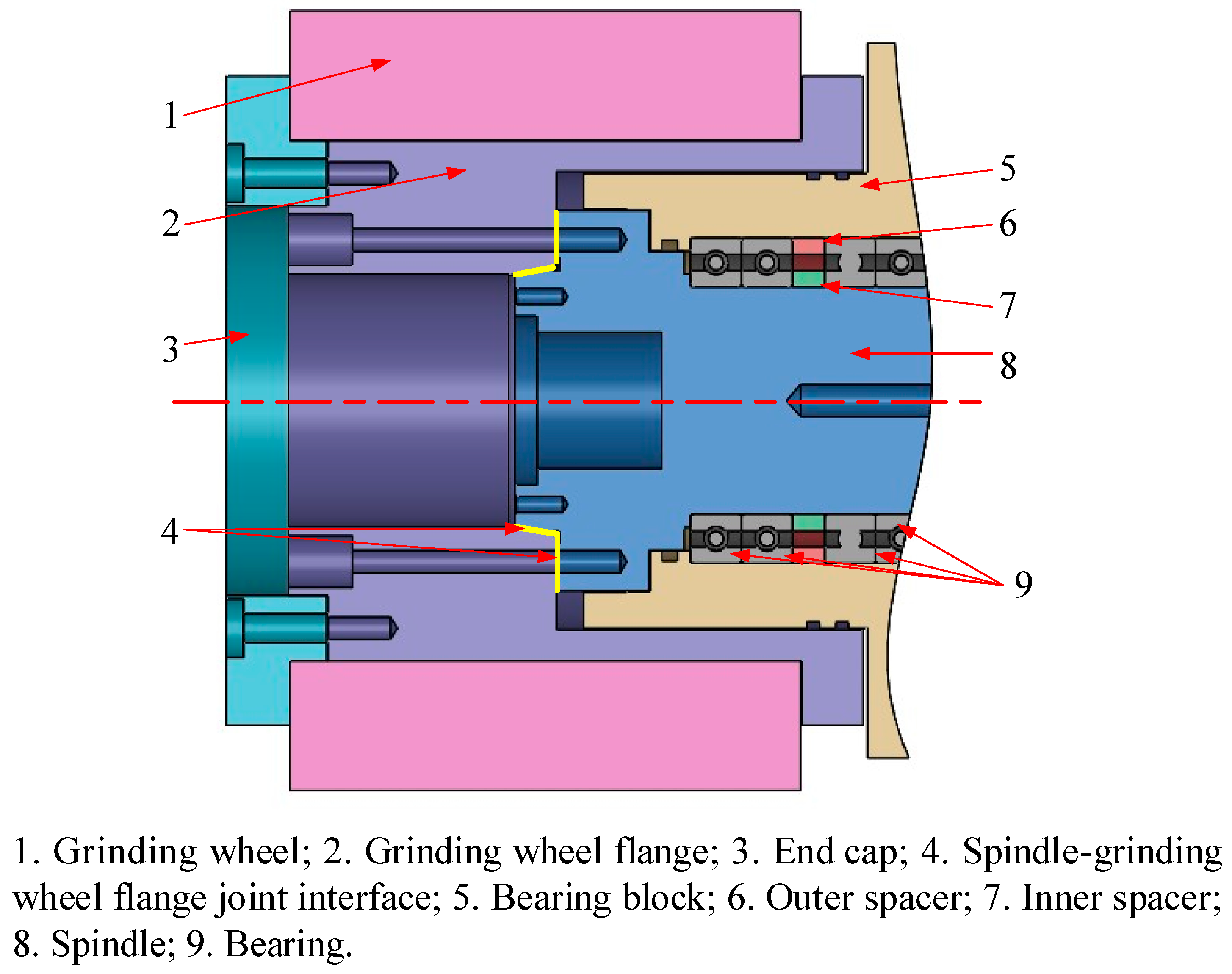
The assembly relationship of the worm grinding-wheel is shown in Figure 1. The GWF and spindle are positioned by the taper and end face. The worm grinding-wheel is installed on the spindle through the GWF and pressed by the end cap. The load and motion of the spindle are transferred to the worm grinding-wheel through the spindle–GWF interface.
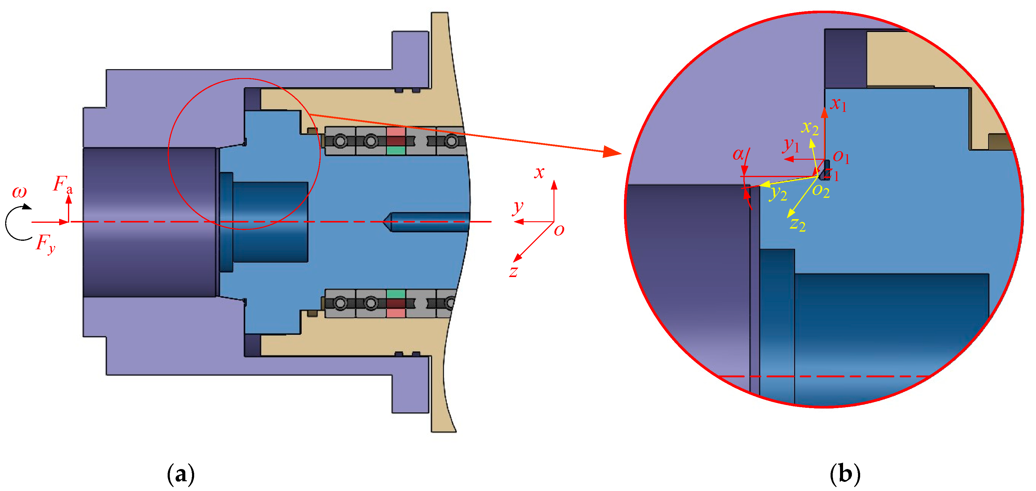
The eccentricity of the spindle-worm grinding-wheel system is inevitable due to the clearance fit between the worm grinding-wheel and the GWF, and the uneven quality of the worm grinding-wheel. In order to eliminate the effect of the worm grinding-wheel eccentricity, the worm grinding-wheel is not considered when performing the spindle–GWF interface stiffness analysis. The forces on the GWF and spindle are bolt preload and centrifugal force, and the forces acting on GWF are shown in Figure 2a. Fy is the axial force caused by the tightening torque applied to the bolt during assembly. Fa is the centrifugal force on the GWF, α is the half-taper angle of the tapered surface, and ω is the rotational speed of the spindle. The coordinate system of spindle–GWF is shown in Figure 2b, where o-xyz is the global coordinate system of the spindle system; o2-x2y2z2 is the local coordinate system of the tapered surface of the spindle–GWF interface; and o1-x1y1z1 is the local coordinate system of the end surface of the spindle–GWF interface.
2.2. Spindle–GWF Interface Contact Stiffness Calculation
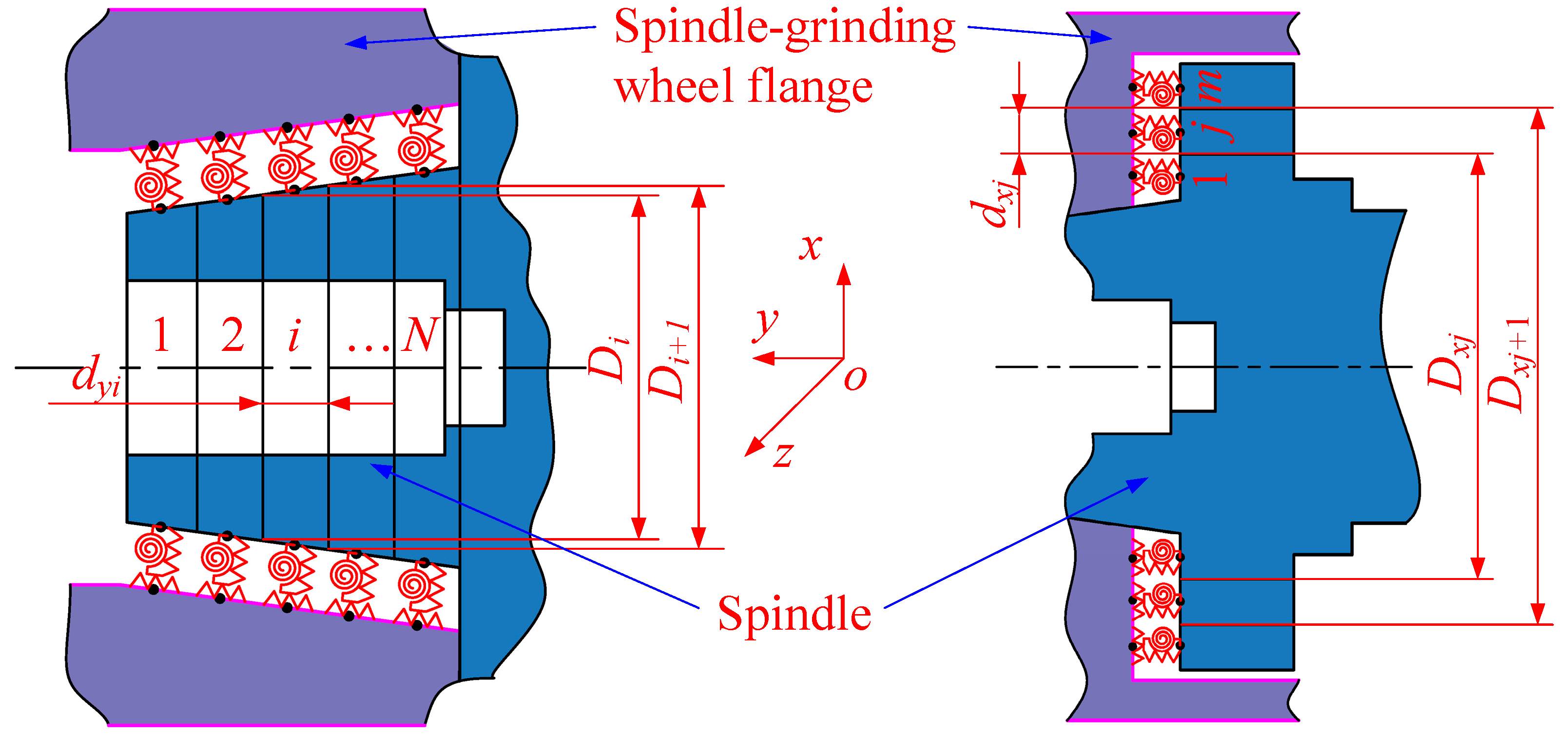
The spindle–GWF interface is modeled by a spring [15,20]. The stiffness of the spindle–GWF interface is equivalent to the spring total stiffness. According to the actual motion of the spindle and the GWF, the spindle has three degrees of freedom: tangential translation, normal translation and mutual rotation. The contact stiffness of the spindle–GWF can be equivalent to axial stiffness, radial stiffness and angular stiffness. Yoshimura proved [30] that the dynamic performances of the interface per unit area are the same for the same average contact pressure. The spindle–GWF interface is the two-sided contact that includes a tapered surface and an end surface. The contact pressure of each unit area on the contact surface is different, so it does not meet the conditions for use of the Yoshimura method. The finite element method is used to divide the tapered interface into N elements and the end interface into m elements, as shown in Figure 3, where dyi is the element length; Di and Di+1 are the diameters of the i-th and i + 1-th node of the taper part of the interface; dxj is the element length; and Dxj and Dxj+1 are the diameters of the j-th and j + 1-th node of the end face of the interface. It is assumed that the contact pressure of each unit area is equal, which satisfies the conditions of the Yoshimura method. According to the Yoshimura method, the stiffness of the spring on each corresponding element can be obtained, and then the total stiffness of the spindle–GWF interface can be calculated according to the spring-parallel relationship.
The spring stiffness of the i-th element is:
where Kni, Kτi are the normal and tangential stiffness of the equivalent spring on the i-th element, respectively; kni, kτi are the normal and tangential contact stiffness on the unit area of the i-th element, respectively; and dS is the area of i-th element.
The contact stiffness per unit area is related to the contact pressure, and the relationship between the interface stiffness and the contact pressure is [29]:
where αn, βn, ατ, βτ are the normal and tangential contact characteristic coefficients, respectively, when the steel–steel contact surface roughness Ra is 0.8 μm, αn = 3.262540 × 10¹², βn = 0.604, ατ = 2.68894 × 10¹¹, and βτ = 0.48 [31]; and Pni is the normal pressure on the i-th element of the interface.
In the global coordinate system, the axial stiffness and radial stiffness on the tapered surface of the spindle–GWF are as follows:
where Kxi, Kyi are the radial contact stiffness and axial stiffness of the equivalent spring on the i-th element.
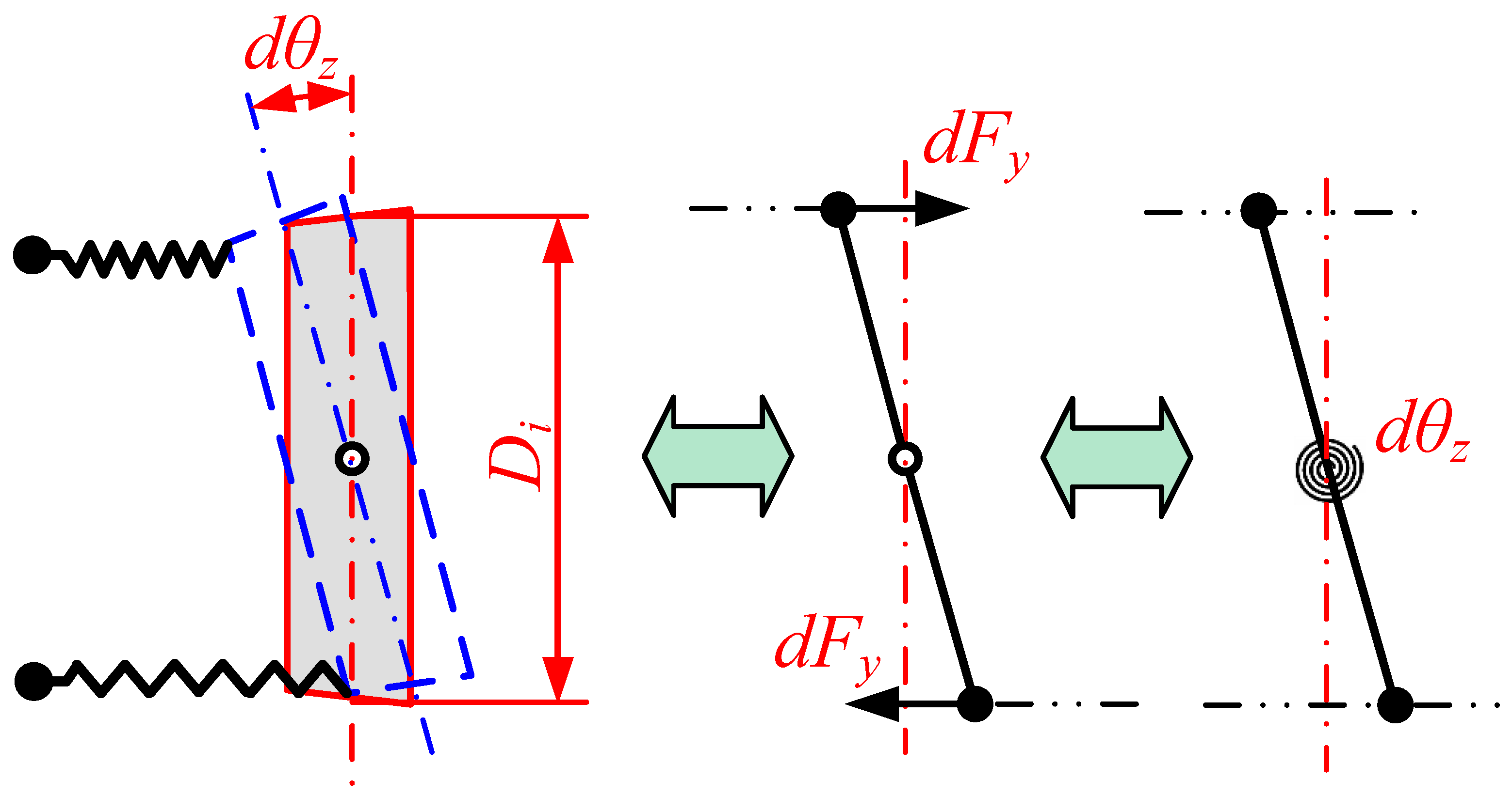
For the i-th element, the translational spring is converted to a rotational spring when the element is deformed by rotation, as shown in Figure 4. When the element causes a small displacement component dyi along the y-axis by the applied force dFy, it will simultaneously rotate around the z-axis by an angle of dθz. According to the relationship between force and displacement, the relationship between axial stiffness and angular stiffness is shown as follows:
where Kθi is the angular stiffness of the equivalent spring on the i-th element, and dMi is the rotational moment of the i-th element relative to the spindle axis.
According to the parallel connection relationship of the equivalent spring at the spindle–GWF interface, the contact stiffness on the taper is given as follows:
According to the parallel connection relationship of the equivalent spring at the spindle–GWF interface, the contact stiffness on the end face is given as follows:
The spindle–GWF interface consists of the tapered surface and the end face. When the two surfaces are in contact, the interface is modeled by equivalent springs that are connected in parallel so that the total stiffness of the spindle–GWF interface is as follows:
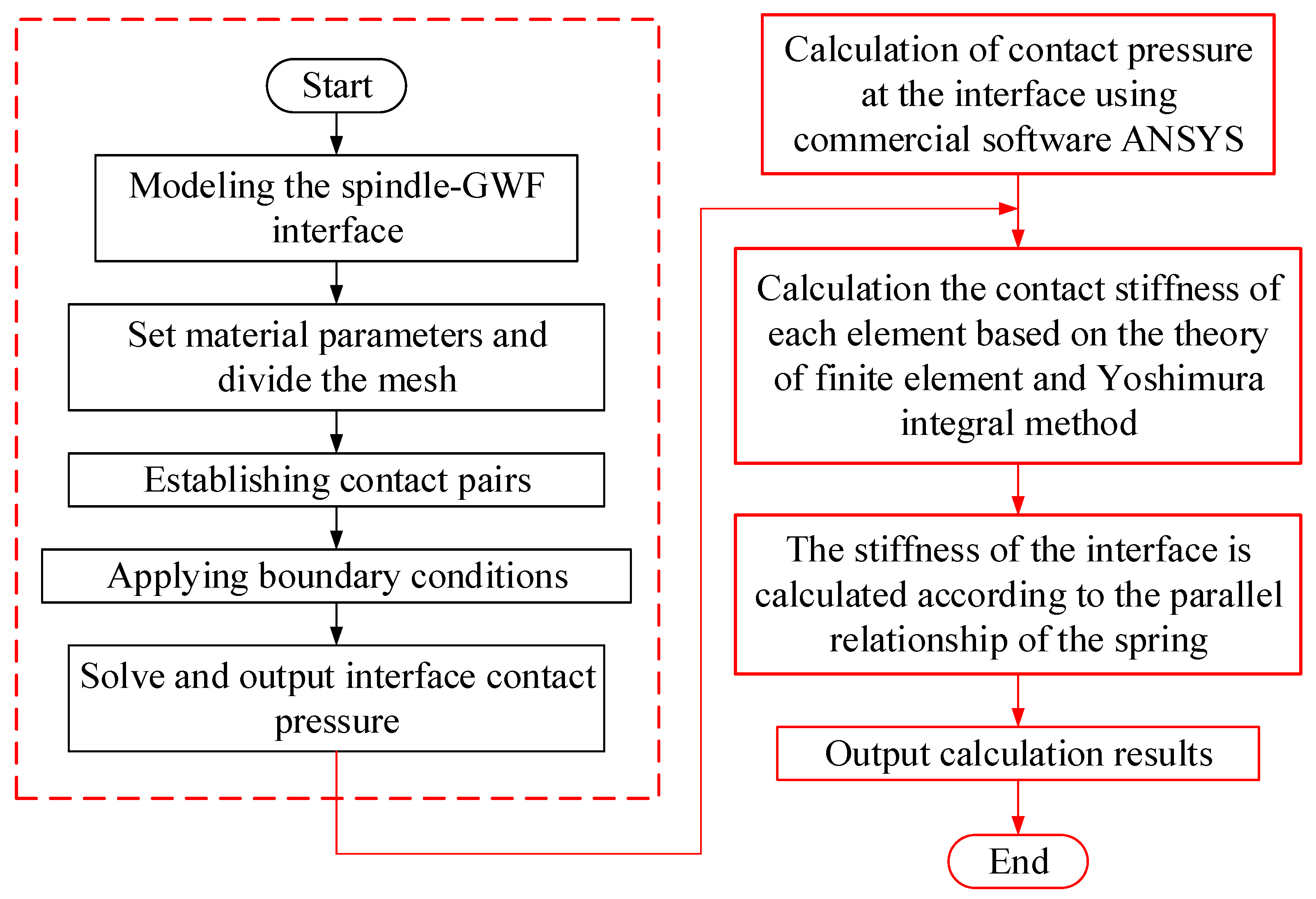
Equations (1)–(8) constitute the calculation model for the contact stiffness of the spindle–GWF interface. Firstly, the contact pressure can be solved using the commercial software ANSYS. Secondly, the calculated contact pressure is brought into Equation (3). Finally, the interface contact stiffness is calculated using Equations (4)–(9). The specific process is shown in Figure 5.
3. Results and Discussions
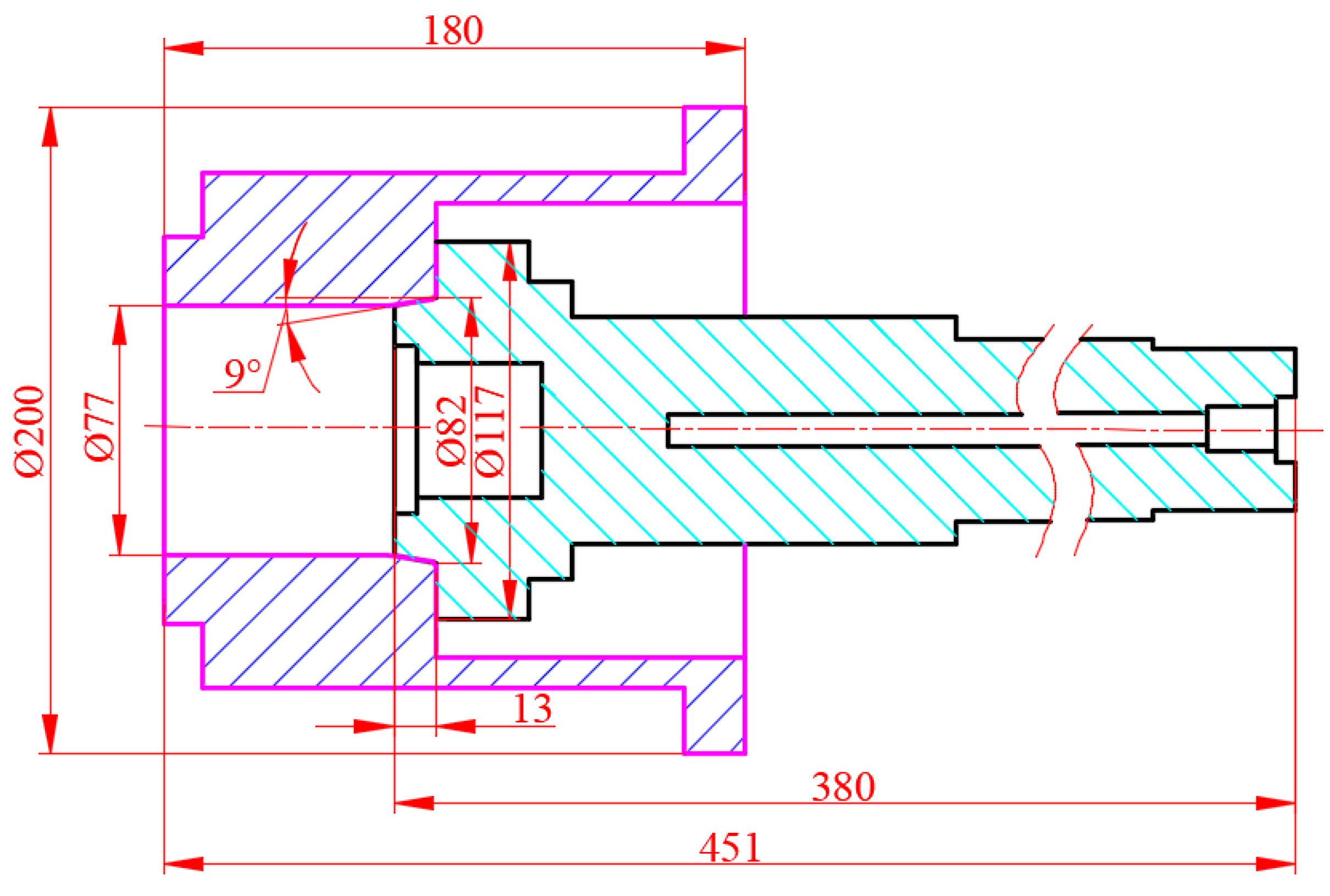
The spindle–GWF interface of the gear precision grinder is studied. The material of the spindle and the GWF is the same steel, Young’s modulus is 2 × 10⁵ MPa, and Poisson’s ratio is 0.3. The main structure parameters of the spindle and the GWF are shown in Figure 6.
3.1. Contact State Analysis of the Spindle–GWF Interface
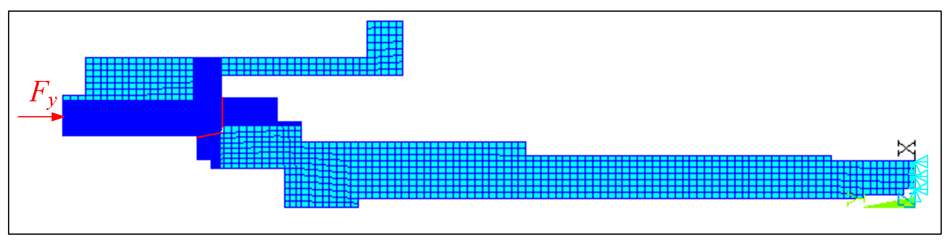
Since the geometry of the spindle and GWF and the loads applied to them are symmetric, axisymmetric elements are used instead of 3D solid elements for modeling when performing FEA. The element type is PLANE182. Structures that have less influence on the contact pressure of the spindle–GWF interface, such as screw holes, oiling holes, bolt holes, etc., are ignored in the modeling. The spindle–GWF mesh and boundary conditions are shown in Figure 7. The boundary condition is that the right end of the spindle is completely fixed, and the axial force is applied on the left end of the GWF. Establishing contact pairs at the spindle–GWF connection, end face and taper of the spindle are target surfaces, and the element type is TARGET169. The end face and taper of the GWF are contact surfaces, and the element type is CONTACT172.
When the original end clearance is 50 μm, the tightening torque is 20 N·m, the contact stiffness of the spindle–GWF interface under different mesh sizes is shown in Table 1. As can be seen from the table, the deviation of the two results does not exceed 4%, which meets the requirements of finite element calculation. In order to improve the calculation speed, the larger mesh size is chosen for the calculation.
The fit clearance between the spindle and GWF includes end clearance and taper clearance. Under no-load conditions, when the end clearance between the spindle and GWF is equal to 0 μm and the taper clearance between the spindle and GWF is greater than 0 μm, the original contact state of the spindle–GWF interface is end contact; when the end clearance between the spindle and GWF is greater than 0 μm and the taper clearance between the spindle and GWF is equal to 0 μm, the original contact state of the spindle–GWF interface is tapered contact; when the end clearance between the spindle and GWF is equal to 0 μm and the taper clearance between the spindle and GWF is equal to 0 μm, the original contact state of the spindle–GWF interface is two-sided contact. The spindle and the GWF are fixed by bolts, and the tightening torque range of the bolts is 20 N·m~50 N·m. the effect of the tightening torque on the contact pressure of the spindle–GWF interface under different contact conditions is analyzed.
- (1)
- End contact
The tapered contact length is the distance of the contact point from the origin of the local coordinate system o2-x2y2z2. The end contact length is the distance between the contact point and the origin of the local coordinate system o1-x1y1z1. When the contact pressures on both contact surfaces are greater than 0 MPa, the interface final contact state is full two-sided contact. When the contact pressures on both contact surfaces are partially greater than 0 MPa, the interface final contact state is partial two-sided contact. When the contact pressures on only one contact surface are greater than 0 MPa, the interface final contact state is end contact or tapered contact.
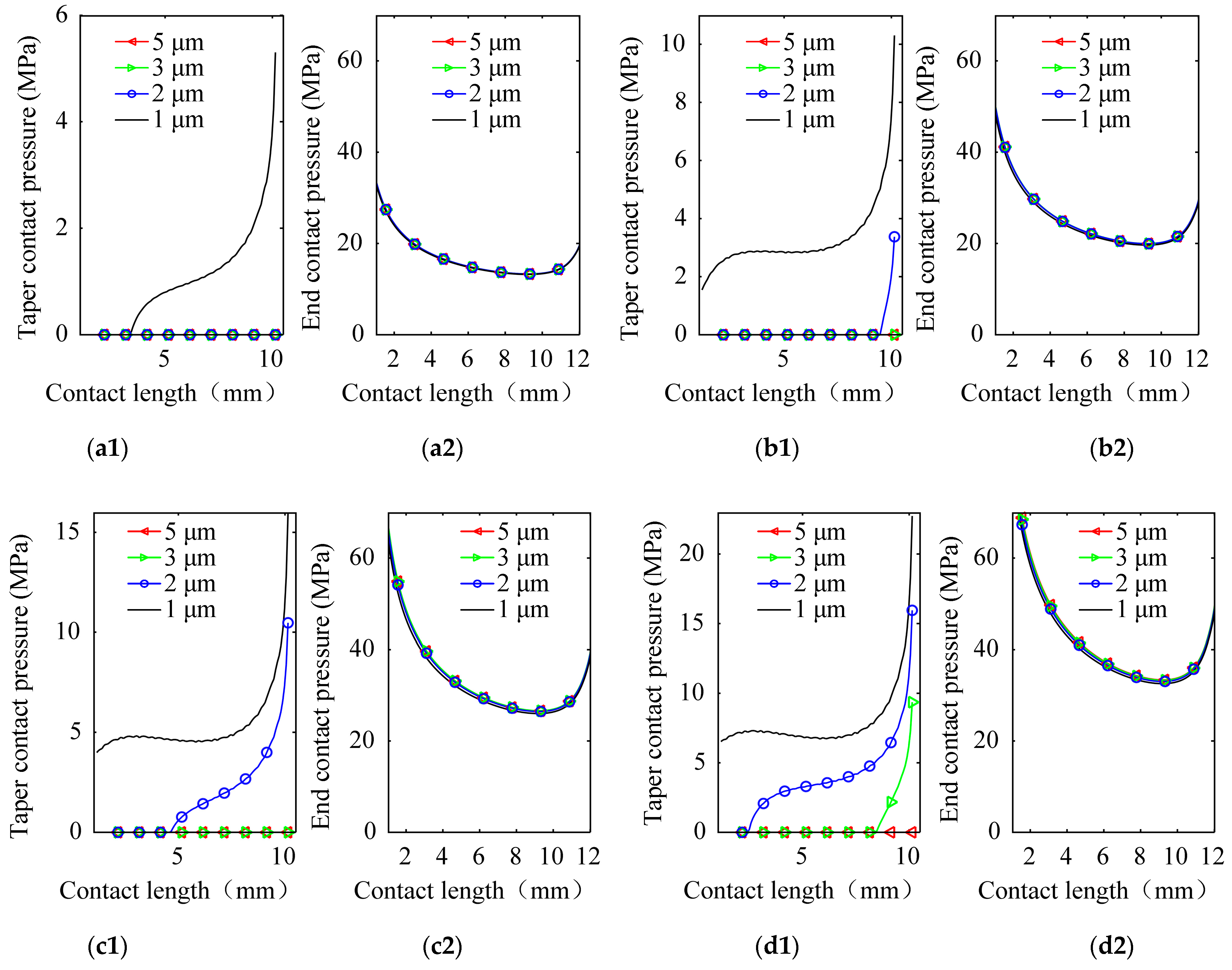
When the original taper clearances are 1 μm, 2 μm, 3 μm and 5 μm, respectively, the effect of the original taper clearance on the contact pressure of the spindle–GWF interface under different tightening torques are as shown in Figure 8. Under the above clearance and tightening torque conditions, the contact state of the end face is full contact, while the tapered face has a transition from no contact to partial contact to full contact. For the end contact pressure, it can be seen from Figure 8(a2,b2,c2,d2) that the overall contact pressure increases as the tightening torque increases, e.g., when the tightening torque is increased from 20 N·m to 50 N·m, the minimum contact pressure increases from 13.2 MPa to 32.5 MPa. However, comparing Figure 8(a2) with Figure 8(d2), it can be seen that the original taper clearance has little effect on the end face pressure distribution when the tightening torque is relatively small. Moreover, when the original taper clearance increases from 1 μm to 5 μm, the maximum value of the contact pressure difference increases as the tightening torque increases, e.g., when the original taper clearance increases from 1 μm to 5 μm, the maximum contact pressure difference is only 2.33 MPa in Figure 8(a2), while the difference is 16.5 MPa in Figure 8(d2). Figure 8(b2,c2) show the same regularity. This is mainly because when the final contact states of the spindle–GWF interface are single-sided contact (Figure 8(a1,a2)) with a taper clearance of 2~5 μm, the load only acts on the end face, the contact area remains the same, and the differences in contact pressure distribution are small. When the original taper clearance is 1μm, the spindle–GWF is partial two-sided contact, and most of the load still acts on the end face due to the small taper angle.
In the case of contact state, the coupling law between the original clearance and the tightening torque is more complex. However, in general, the increase in tightening torque effectively increases the length of the tapered contact. As an example, when the original taper clearance is 1 μm, it can be seen from the black curves in Figure 8(a1,b1,c1,d1) that the final contact state of taper changes from partial contact to full contact as the tightening torque increases. When the original taper clearance is 2 μm (blue curve in Figure 8), the final contact state transitions from no contact (Figure 8(a1)) to a minority of partial (Figure 8(a1,c1)) to a majority of full contact (Figure 8(d1)). However, when the clearance is too large, such as an original clearance of 5 μm (red curve in Figure 8), the tightening torque does not effectively eliminate the original taper clearance, and the final contact state of the spindle–GWF interface is always in end contact. From Figure 8, it can be seen that when the original taper clearance is 1 μm and the tightening torque is from 30 N·m to 50 N·m the contact state of the spindle–GWF interface after assembly is full two-sided contact. The above phenomena show that the final contact state of the spindle–GWF interface is a result of the coupling action of the original clearance and the tightening torque, which will certainly lead to a complex coupling relationship between the contact stiffness, the original clearance and the tightening torque.
- (2)
- Tapered contact
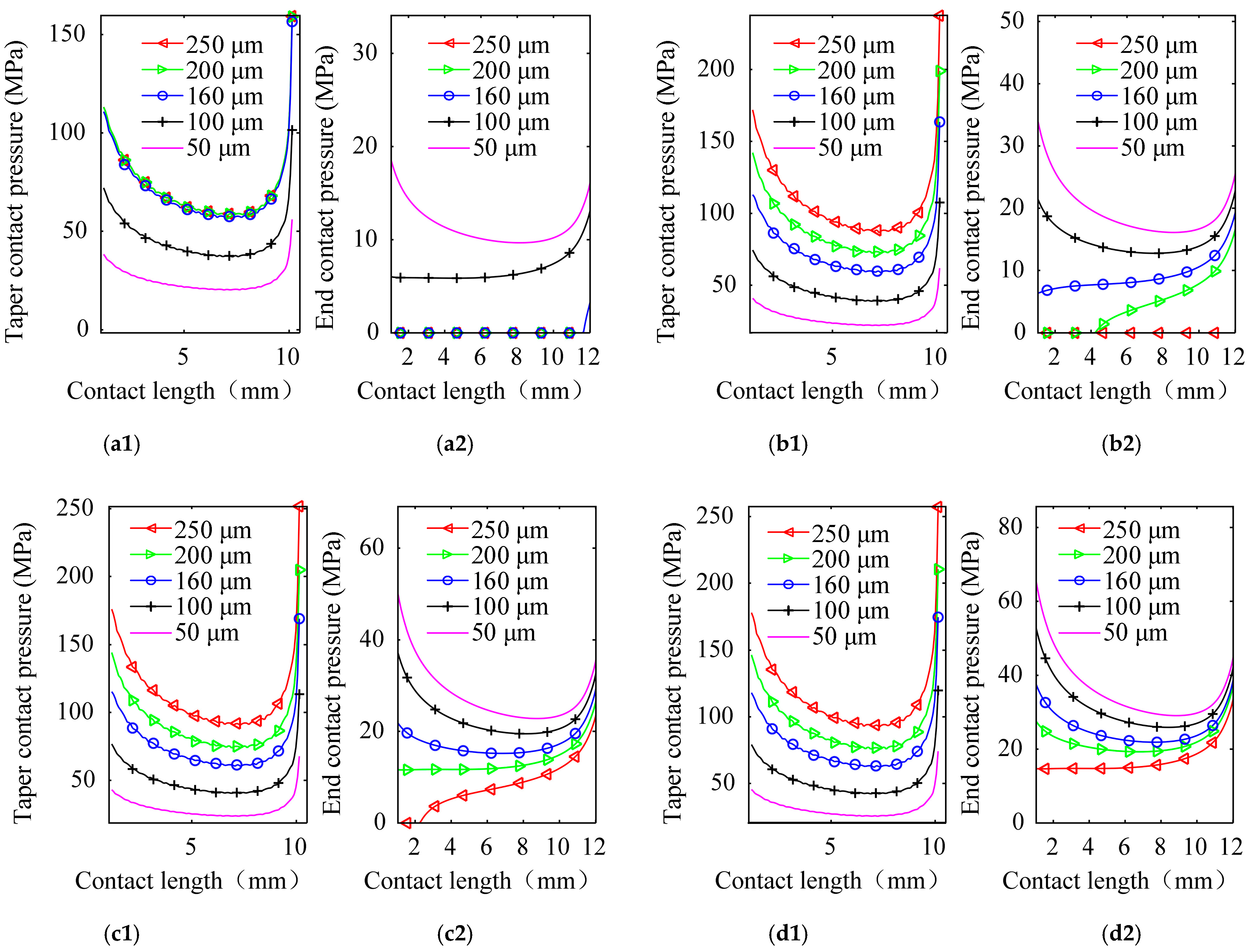
When the original end clearances are 50 μm, 100 μm, 160 μm, 200 μm and 250 μm, respectively, the effects of the original end clearance on the contact pressure of the spindle–GWF interface under different tightening torques are shown in Figure 9. Under the above end clearance and tightening torque conditions, the final contact state of taper is full contact, while the end face has a transition from no contact to partial contact to full contact. For the contact pressure on the interface, it can be seen from Figure 9 that the overall contact pressure increases as the tightening torque increases. As shown in Figure 9(a1,b1,c1,d1), when the tightening torque is increased from 20 N·m to 50 N·m, the minimum tapered contact pressure increases from 20.2 MPa to 25.3 MPa. As shown in Figure 9(a2,b2,c2,d2), when the tightening torque is increased from 20 N·m to 50 N·m, the minimum end contact pressure increases from 0 MPa to 14.7 MPa. However, comparing Figure 9(a1) with Figure 9(d1), it can be seen that when the tightening torque is relatively small, the effect of the original end clearance on the pressure distribution on the tapered surface is influenced by the contact state. As shown in Figure 9(a1), when the original end clearances are greater than 160 μm, the final contact state is tapered contact or a minority of partial two-sided contact, and the difference in contact pressure between the end contact clearances of 160 μm and 250 μm is only 2.78 MPa. When the original end clearances are less than 100 μm, the final contact states are full two-sided contact, and the difference in contact pressure between the end clearances of 50 μm and 100 μm is 45.4 MPa. Meanwhile, in Figure 9(d1), as the end clearance increases, the contact pressure on the tapered surface decreases and the contact pressure on the end surface increases. Figure 9(b1,c1) show the same regularity. This is mainly because when the final contact states of the spindle–GWF interface are single-sided contact (Figure 9(a1,a2)) with a taper clearance of 160~250 μm, the load only acts on the tapered face, the contact area remains the same, and the differences in contact pressure distribution are small. When the final contact states of the spindle–GWF interface are two-sided contact, the load applied to the tapered surface increases with the increase in the original end clearance, while the load applied to the end surface decreases with the increase in the original end clearance.
In the case of the contact state, a more complex coupling law is reflected between the original end clearance and the tightening torque. An increase in the tightening torque effectively increases the length of the end contact. Taking the original end clearance of 160 μm as an example, the blue curves in Figure 9(a2,b2,c2,d2) show that the tapered final contact state changes from a partial contact state (Figure 9(a2)) to a full contact state (Figure 9(b2,c2,d2)) as the tightening torque increases. When the clearances are 200 μm and 250 μm, the contact states of the spindle–GWF interface have the same regularity with an increase in tightening torque (the green curves and red curves in Figure 9(a2,b2,c2,d2)). From Figure 9(a2,b2,c2,d2), it can be seen that the original end clearance can be effectively eliminated as the tightening torque increases, so that the final contact state of the spindle–GWF interface is full two-sided contact. When the tightening torque is 20 N·m and the original end clearances are less than or equal to 100 μm, the tightening torque is 30 N·m and the original end clearances are less than or equal to 160 μm; when the tightening torque is 40 N·m and the original end clearances are less than or equal to 200 μm, the tightening torque is 50 N·m; and when the original end clearances are less than or equal to 250 μm, the final contact states of the spindle–GWF interfaces after assembly are full two-sided contact. The above phenomena show that when the original contact state of the spindle–GWF interface is tapered contact, increasing the tightening torque can effectively change the contact state of the interface.
- (3)
- Two-sided contact
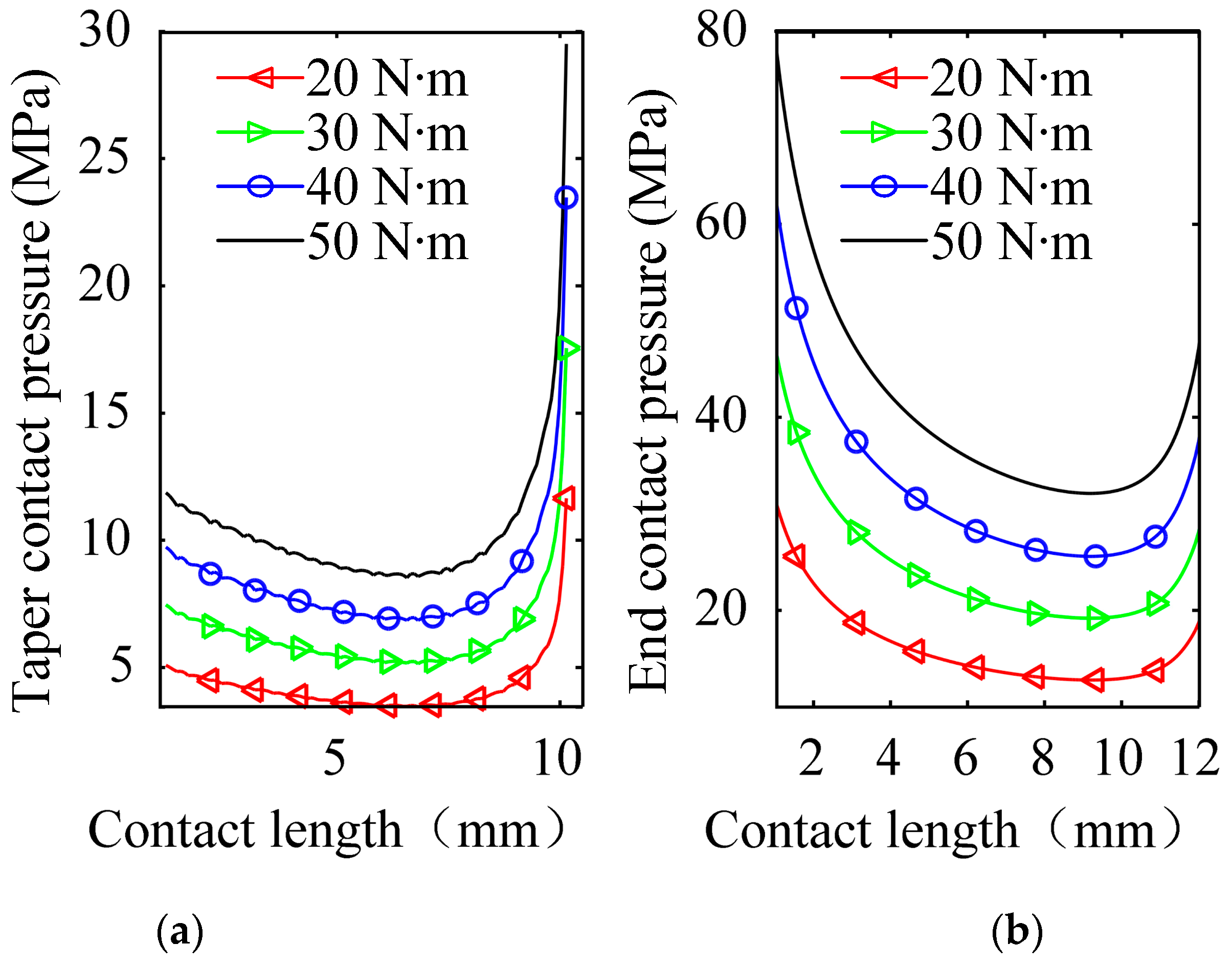
When the original contact state of the spindle–GWF interface is two-sided contact and the tightening torques are 20 N·m, 30 N·m, 40 N·m and 50 N·m, respectively, the effect of the tightening torque on the contact pressure at the spindle–GWF interface is as shown in Figure 10. Under the above conditions of clearance and tightening torque, the interfaces are in full two-sided contact. It can be seen from Figure 10 that the overall contact pressure increases as the tightening torque increases. When the tightening torque increases from 20 N·m to 50 N·m, the minimum contact pressure at the tapered surface increases from 3.5 MPa to 8.5 MPa, and the minimum contact pressure at the end surface increases from 12.8 MPa to 32.1 MPa. This is because the increase in tightening torque does not change the contact state in the case of two-sided contact. Since the contact area remains constant, the contact pressure increases with the increase in the tightening torque.
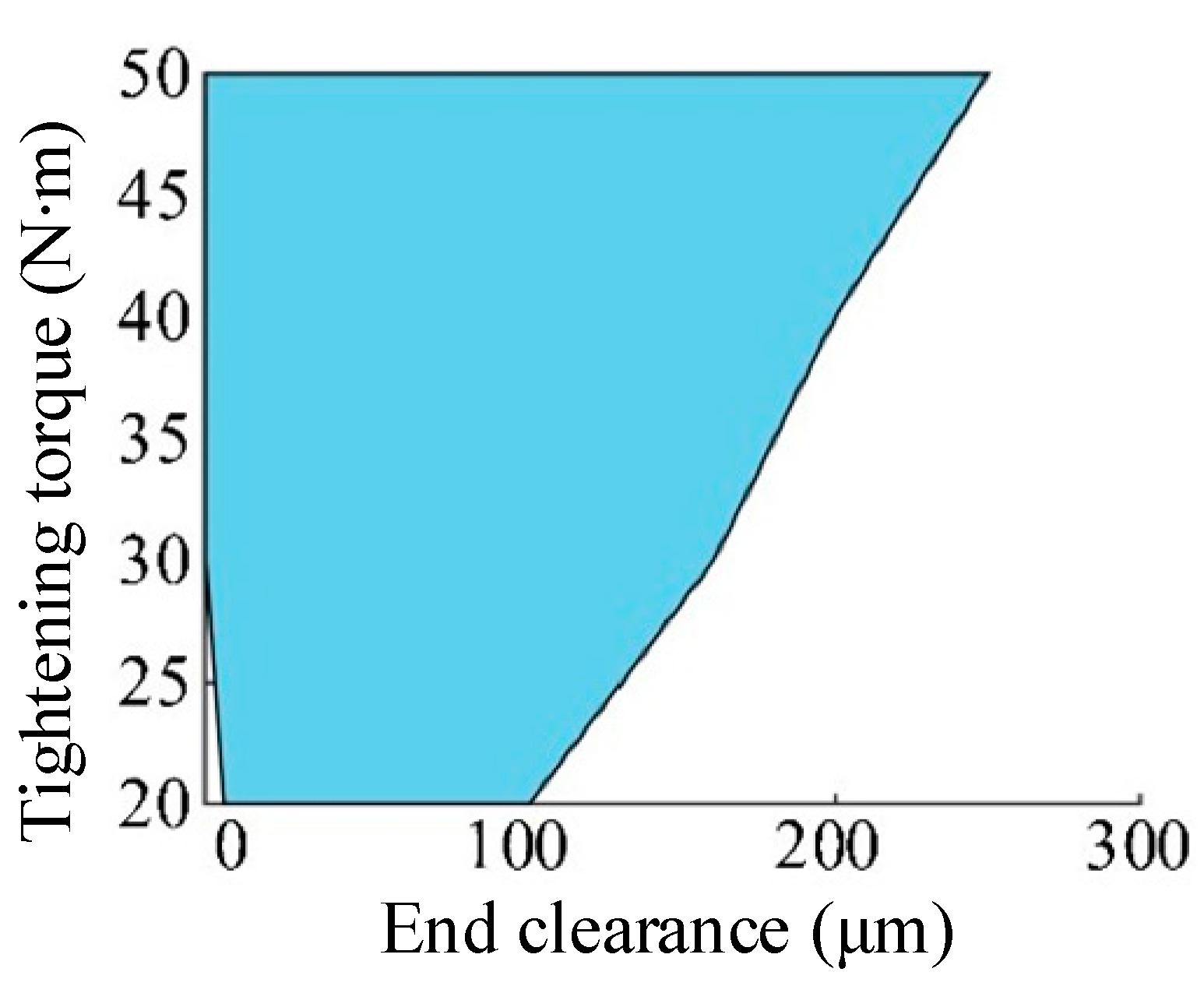
According to the geometric relationship between the tapered surface and the end face of the spindle–GWF interface, the relationship between the taper clearance ut and the end clearance ue is . When the final contact states of the spindle–GWF interface after assembly are two-sided contact, the range of assembly parameters are as shown in Figure 11. When the original end clearance and tightening torque are within the blue area, the final contact state of the spindle–GWF interface after assembly is two-sided contact. In engineering, GWF assembly can be guided by the original end clearance and Figure 11.
3.2. Analysis of Factors Affecting the Contact Stiffness of the Spindle–GWF Interface
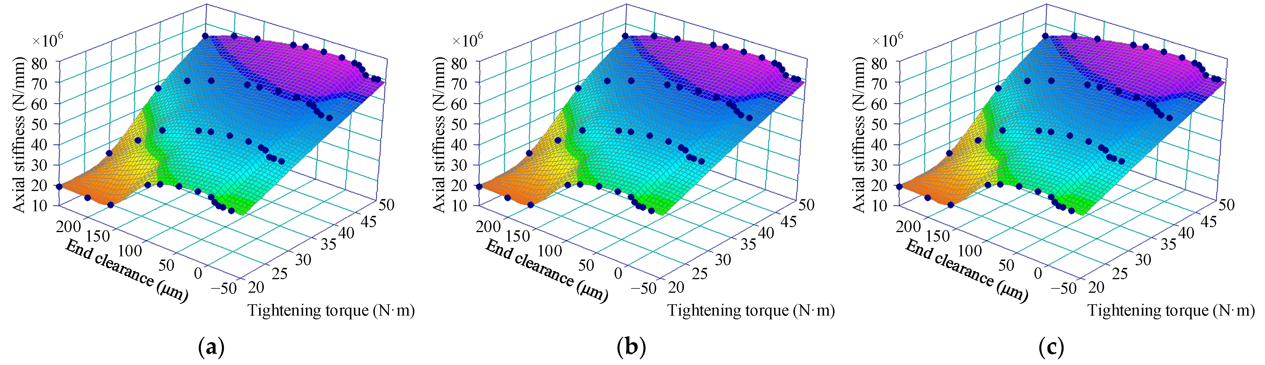
There is a complex coupling between the contact stiffness of the bonding surface and the original clearance and tightening torque. The effect of original end clearance and tightening torque on the spindle–GWF joint stiffness is shown in Figure 12. In Figure 12, the dots are the simulation results. According to the simulation results, using the commercial software TableCurve, AkimaIII interpolation is used to plot the relationship surfaces between end face clearance, tightening torque and bond surface stiffness, as shown on the surface of Figure 12. In engineering, the bond surface stiffness can be determined by the original end clearance and tightening torque, according to Figure 12. In Figure 12, it can be found that with the same tightening torque, the axial stiffness and angular stiffness of the spindle–GWF interface increases when the original end clearance increases, while the radial stiffness of the spindle–GWF interface decreases when the original end clearance increases. At the same original end clearance, the stiffness of the spindle–GWF interface increases when the tightening torque increases. When the tightening torque is 20 N·m and the original end clearances are greater than 200 μm, the contact stiffness values of the spindle–GWF interface are equal. This is because when the original end clearances are greater than 200 μm, only the taper is contacted, the end face is not contacted, and the contact pressure of the spindle–GWF interface remains constant. When the tightening torques are 20 N·m, 30 N·m, 40 N·m and 50 N·m, the original end clearance is increased from 0 μm by 250 μm; the axial stiffness of the spindle–GWF interface decreases by 53.5%, 54.1%, 26.6% and 13.4%; the radial stiffness increases the spindle–GWF interface by 393.1%, 396.8%, 335.8% and 289.8%; and the angular stiffness of the spindle–GWF interface decreases by 70.7%, 71.1%, 36.2% and 22.2%, respectively. According to the geometric relationship between the tapered surface and the end face of the spindle–GWF interface, when the original end clearances are negative and the taper clearance is 0 μm, the original contact state of the spindle–GWF interface is end contact. When the original contact state is end contact, the tightening torque is 20 N·m and the original end clearances are less than −6.4 μm; when the tightening torque is 30 N·m and the original end clearances are less than −12.8 μm, the tightening torque is 40 N·m; when the original end clearances are less than −19.2 μm, the tightening torque is 50 N·m; and when the original end clearances are less than −32 μm, the contact stiffness values of the spindle–GWF interface are equal. When the tightening torques are 20 N·m, 30 N·m, 40 N·m and 50 N·m, the original end clearance is increased from −32 μm to −6.4 μm; the axial stiffness of the spindle–GWF interface increases by 2.9%, 4.9%, 5.1% and 5.6%; the radial stiffness of the spindle–GWF interface increases by 72.9%, 84.1%, 86.1% and 87.6%; and the angular stiffness of the spindle–GWF interface increases by 1.5%, 2.6%, 2.5% and 2.8%, respectively. This is because according to the relationship between end clearance and taper clearance, when the original clearance of the taper is greater than 0 μm and the original clearance of the end face is 0 μm, it is equivalent to a taper clearance of 0 μm, and the original clearance of the end face is negative. When the end clearance reaches a certain value, when the tapered surface is not contacted and when the stiffness is mainly from the end face, the contact stiffness of the spindle–GWF interface tends to be stable; the tapered contact area decreases as the end clearance increases; the contact pressures of the spindle–GWF interface increase; and the contact stiffness increases. The above phenomena show that the effect of the original end clearance on the radial stiffness of the spindle–GWF interface is greater than that of the axial and angular stiffness of the spindle–GWF interface for the same tightening torque.
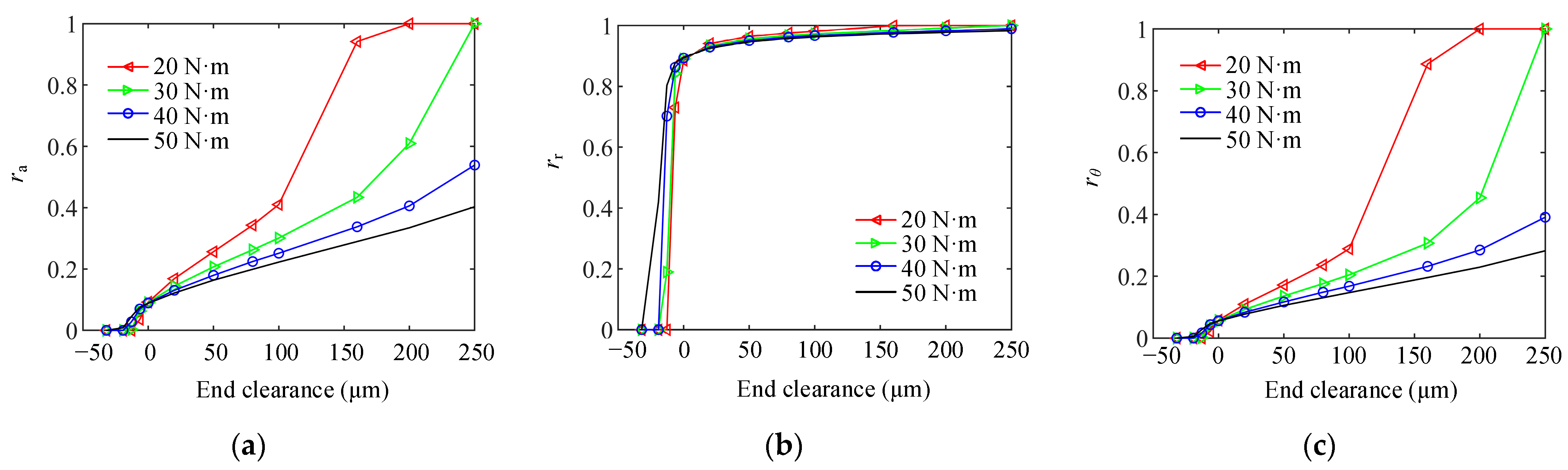
The effects of original end clearance on the ratio of taper stiffness to the spindle–GWF interface stiffness at different tightening torques are shown in Figure 13, where ra is the ratio of taper axial stiffness to the spindle–GWF interface axial stiffness; rr is the ratio of tapered radial stiffness to the spindle–GWF interface radial stiffness; and rθ is the ratio of tapered angular stiffness to the spindle–GWF interface angular stiffness. From Figure 13, it can be found that the ratio of tapered stiffness to the spindle–GWF interface stiffness increases when the original end clearance increases. When the final contact state of the spindle–GWF interface is full two-sided contact after loading (see Figure 11 for tightening torque and end clearance parameters), the maximum ratio of tapered axial stiffness to the spindle–GWF interface axial stiffness is 0.43. The original end clearance is less 0 μm; the maximum ratio of tapered axial stiffness to the spindle–GWF interface axial stiffness is only 0.09; and the maximum ratio of tapered angular stiffness to the spindle–GWF interface angular stiffness is only 0.06. The tightening torque has little effect on these ratios. The ratio of tapered radial stiffness to the spindle–GWF interface radial stiffness is greater than 0.84. As the original end clearance increases, the ratio of tapered radial stiffness to the spindle–GWF interface radial stiffness increases up to 1. This is because as the original end clearance increases, the contact area of the end face gradually decreases to 0. The above phenomena show that when the final contact state of the spindle–GWF interface is two-sided contact after loading, the axial stiffness and angular stiffness mainly come from the end face, while the radial stiffness mainly comes from the tapered surface.
When the final contact state of the spindle–GWF interface is full two-sided contact after being loaded, the axial stiffness and angular stiffness of the spindle–GWF interface are mainly from the end face, and the radial stiffness of the spindle–GWF interface is mainly from the taper. When the original contact state of the spindle–GWF interface is tapered contact or two-sided contact, it is easier to ensure the radial stiffness of the spindle–GWF interface after assembly. When the original contact state is end contact, it is difficult to ensure the radial stiffness and full two-sided contact of the spindle–GWF interface after assembly. In order to ensure sufficient rigidity and stability of the spindle–GWF interface, the original contact state between the spindle and the GWF should be tapered contact or two-sided contact.
4. Experimental Verification
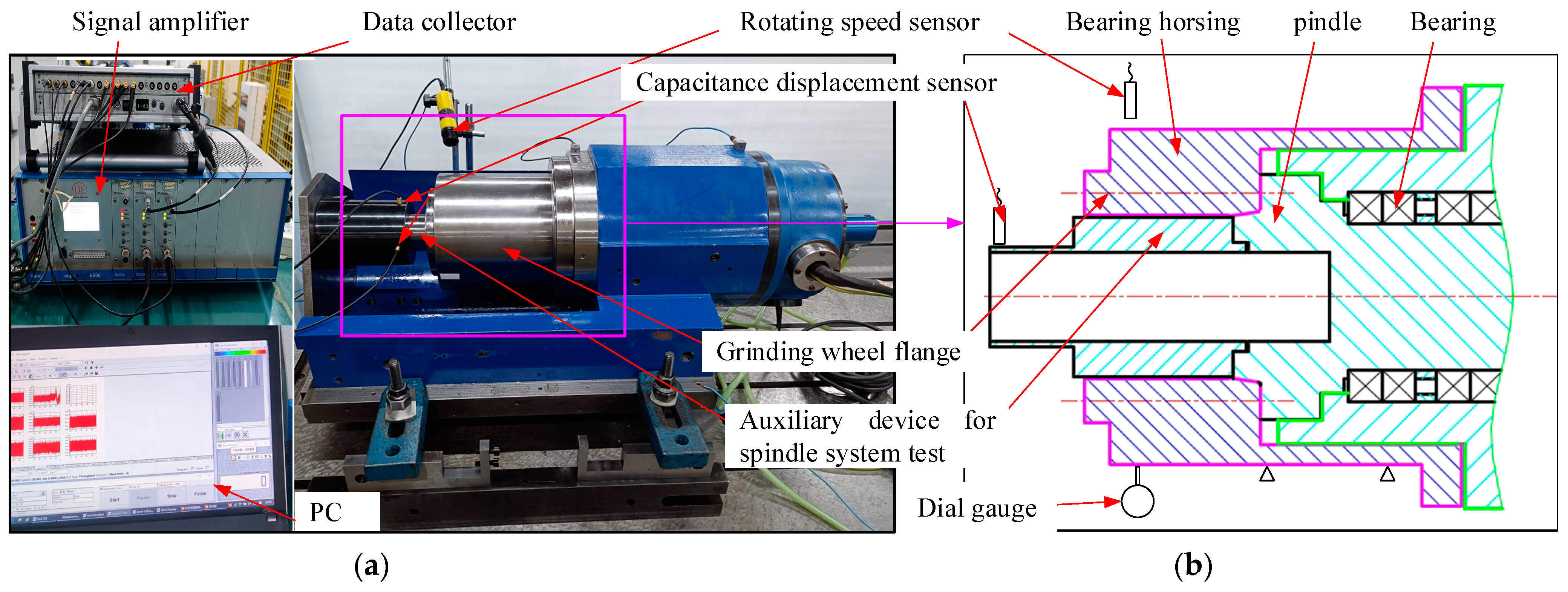
The interface stiffness cannot be measured directly, and is usually obtained indirectly by measuring the frequency response of the system at different points [19,20,21,22,23]. To identify and separate the dynamic characteristics of related structures, it is necessary to establish the dynamic equation with the Timoshenko beam theory. Moreover, some parameter optimization algorithms, such as the genetic algorithm and particle swarm optimization, are used to identify the parameters of the interface. The solution is influenced by the initial value, crossover rate and variation rate; the calculation is large, and the measuring instrument must have a very high resolution. Therefore, it is very difficult to measure, identify and separate the interface stiffness. Because the stiffness of the interface affects the spindle system stiffness, and then affects its dynamic characteristics, the smaller the stiffness of the spindle system, the greater the vibration. The greater the stiffness of the shaft system, the higher the cutting stability [32]. In order to quickly compare the radial stiffness of the three contact states, the interface stiffness can be verified indirectly by measuring the displacement amplitude of vibration of the spindle system. Therefore, the effect of the spindle–GWF interface original contact state on the contact stiffness can be indirectly verified by the effect of the spindle–GWF interface contact state on the spindle system vibration. A vibration characteristics test rig of a grinding machine spindle system was established, as shown in Figure 14a, and was an actual grinding machine spindle system. In the experiment, the electro-spindle rotating speed was adjusted by an inverter (model ACS880-01-072A-3+D150) and was measured using a Laser Tacho Probe-MM0360 rotating speed sensor. The radial vibration displacement of the spindle end was measured by a displacement sensor mounted on the shaft end. The displacement sensor model was capaNCDT6500, probe model CS1, with a measurement range of 0~500 μm. The signal acquisition device was Pak mobile MK Ⅱ.
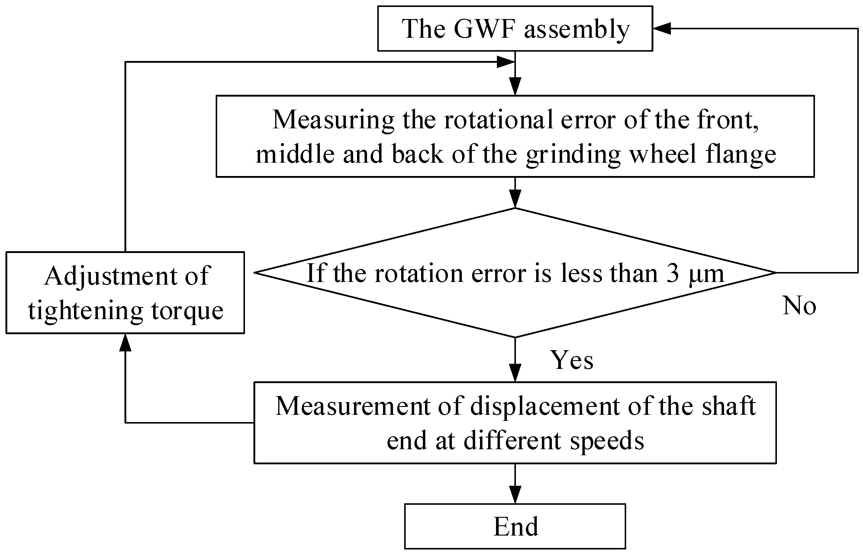
The test flow of the spindle vibration is shown in Figure 15. The GWF was installed on the spindle under the action of tightening torque. After installation, the rotation error was measured at the front, middle and rear of the grinding wheel flange. When the rotation error was less than 3 μm, the experiment was started. After the experiment, the tightening torque was adjusted or the GWF replaced, and the above operation was repeated, until the experiments for the three contact states under four tightening torques were completed. During the experiment, the spindle speed was 2000 r/min, and the vibration signal of the spindle was measured using a displacement sensor. The time-frequency signal was filtered using a finite impulse response filter with a filter frequency of 5 Hz.
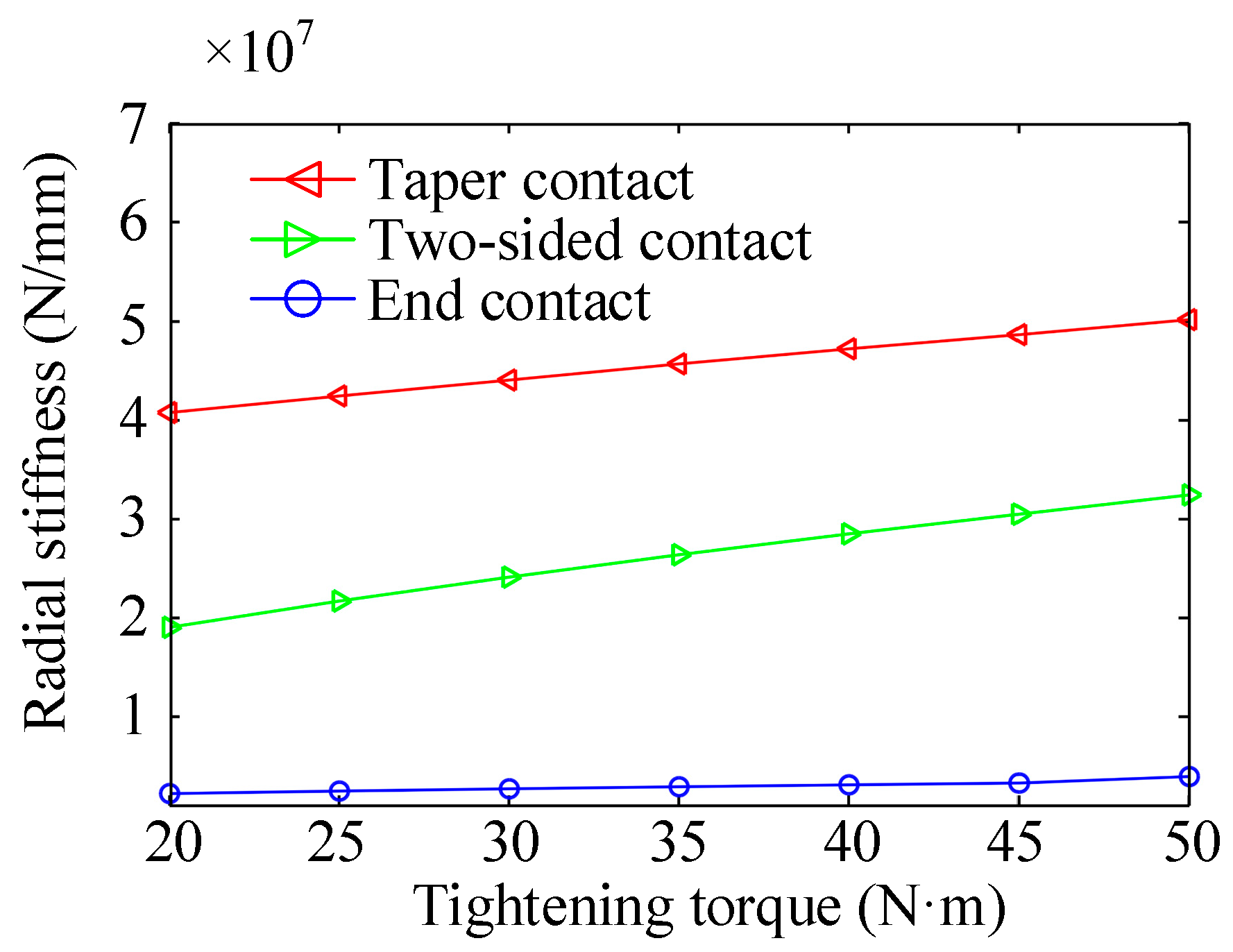
The parameters of the three original contact states of the spindle–GWF were as follows: the original contact state of the spindle–GWF interface was end contact with an end-face interference of 20 μm and a taper clearance of 0 μm; the original contact state of the spindle–GWF interface was tapered contact with an end clearance of 30 μm and a taper clearance of 0 μm; the original contact state of the spindle–GWF interface was two-sided contact with an end clearance of 0 μm and a taper clearance of 0 μm. According to the calculation method of interface stiffness in part 2, the radial stiffness of the three original contact states was obtained using a simulation, as shown in Figure 16. It can be seen that in the three contact states, the radial stiffness is the smallest in end contact, the second largest in two-sided contact, and the largest in tapered contact. In all three original contact states, the contact stiffness increases with increasing tightening torque, while for end contact, this change is not significant.
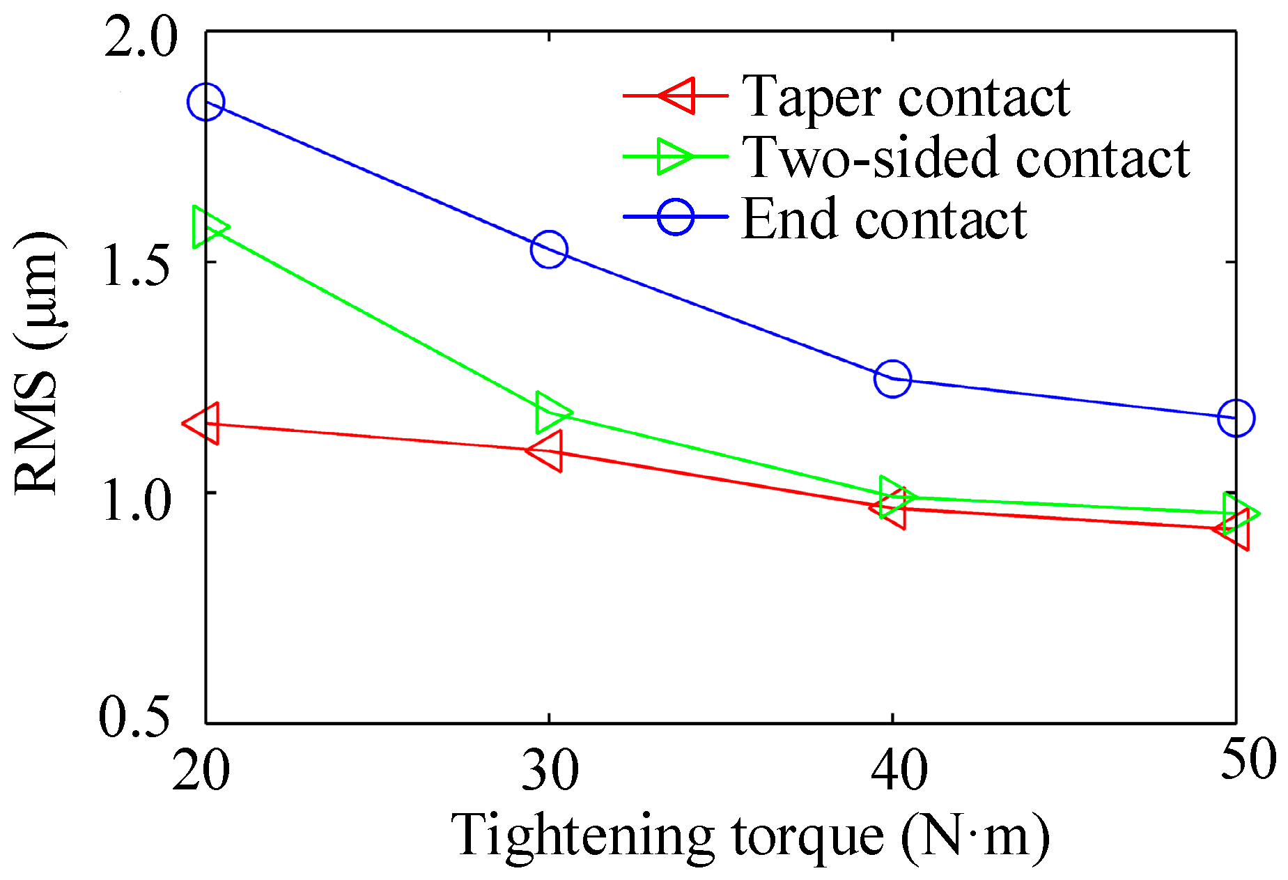
Here, the root mean square (RMS) of the time-frequency vibration signal was used to describe the vibration amplitude. The RMS values of spindle radial vibration for the three original contact states are shown Figure 17. It can be seen that the RMS of radial vibration displacement of the spindle in the three original contact states is the smallest in the tapered contact, the second largest in the two-face contact, and the largest in the end-face contact. This is consistent with the law that states that the greater the stiffness of the spindle–GWF interface, the smaller the vibration. As the tightening torque increases, the RMS values in the three original contact states decrease. This law has the same trend as the effect of the tightening torque on the radial stiffness of the spindle–GWF interface, but the degree of reduction is different. This is because the spindle vibration is not only related to the contact stiffness of the spindle–GWF interface, but it is also affected by the contact state of the spindle–GWF interface. As can be seen from Figure 8, when the end clearance is 20 μm and the tightening torque is less than 40 N·m, the contact state of the spindle–GWF interface after assembly is end contact, and the tapered surface is not in contact. The lack of radial positioning between the spindle and the GWF results in poor radial stability of the spindle and expansion of the spindle radial vibration. As the tightening torque increases, the tapered contact area increases and radial vibration decreases rapidly. It is also indirectly verified that the spindle operation is more stable when the spindle–GWF contact state is two-sided contact after assembly.
5. Conclusions
In order to study the influence of fit clearance and tightening torque on interface characteristics, a two-sided contact stiffness model considering fit clearance was established. Based on this model, the influence of fit clearance and tightening torque on the contact state and contact stiffness of the interface was analyzed, and vibration test experiments were used to indirectly verify the accuracy of the stiffness model of the spindle–GWF interface. The main conclusions are as follows:
- (1)
- Based on the finite element and Yoshimura integration methods, the calculation method of the contact stiffness for the two-sided contact of a tapered surface and an end face is proposed.
- (2)
- The effects of tightening torque, original end clearance and original taper clearance on the contact pressure, final contact state and interface stiffness of the spindle–GWF interface were analyzed. It was found that increasing the tightening torque and reducing the clearance could improve the contact states of the spindle–GWF interface. However, when the original contact state of the spindle–GWF interface is end contact, the final contact state after assembly is difficult to change by increasing the tightening torque. At the same clearance, increasing the tightening torque can improve the stiffness of the interface. Under the same conditions, the change in radial stiffness by changing the clearance is much larger than the change in axial stiffness and angular stiffness.
- (3)
- In engineering, the final contact state and contact stiffness of the spindle–GWF interface after assembly can be determined based on the original end clearance, tightening torque, contact state and contact stiffness of the spindle–GWF interface relationship figures.
- (4)
- A spindle–GWF vibration test bench was established, and it was found that when the original contact state of the spindle–GWF interface is tapered, the spindle vibration is the smallest. Moreover, it was indirectly verified that the radial stiffness of the spindle–GWF interface is the largest when tapered contact is made, which is in accordance with the simulation law.
This paper presents a mathematical model for calculation of the contact stiffness of two-sided contact. The proposed model can be applied to preload the relationship between clearance of the interface, the tightening torque, the contact state and the contact stiffness of the spindle–GWF interface, which is important for guiding the assembly of the spindle–GWF system.
Author Contributions
Conceptualization, Q.Y.; methodology, Q.Y. and Y.Z.; validation, X.Z., K.Y. and Q.Y.; formal analysis, Q.Y. and X.Z.; investigation, Y.Z. and K.Y.; resources, Y.Z.; data curation, Y.Z. and Q.Y.; writing—original draft preparation, Q.Y.; writing—review and editing, Y.Z., K.Y. and Q.Y.; supervision, Y.Z.; project administration, Y.Z.; funding acquisition, Y.Z. All authors have read and agreed to the published version of the manuscript.
Funding
This research was funded by the Key R&D Program of Shaanxi Province (No. 2021LLRH-01-022).
Institutional Review Board Statement
Not applicable.
Informed Consent Statement
Not applicable.
Data Availability Statement
Detailed data are contained within the article.
Conflicts of Interest
The authors declare no conflict of interest.
References
- Lin, D. Study on Diagnostic and Controlling Techniques for Grinding Wheel Spindle Vibration. Master’s Thesis, Xi’an Jiaotong University, Xi’an, China, 2013; p. 2. [Google Scholar]
- Li, L.; Wang, J.J.; Shi, X.H.; Ma, S.L.; Cai, A.J. Contact Stiffness Model of Joint Surface Considering Continuous Smooth Characteristics and Asperity Interaction. Tribol. Lett. 2021, 69, 43. [Google Scholar] [CrossRef]
- Ma, S.J.; Zhang, X.Z.; Yan, K.; Zhu, Y.S.; Hong, J. A Study on Bearing Dynamic Features under the Condition of Multiball–Cage Collision. Lubricants 2022, 10, 9. [Google Scholar] [CrossRef]
- Sun, C.; Duan, J.T.; Lan, D.X.; Liu, Z.X.; Xiu, S.C. Prediction about Ground Hardening Layers Distribution on Grinding Chatter by Contact Stiffness. Arch. Civ. Mech. Eng. 2018, 18, 1626–1642. [Google Scholar] [CrossRef]
- Yao, L.; Wang, X.F.; Lin, J.; Kong, X.G. An Adaptive Grinding Chatter Detection Method Considering the Chatter Frequency Shift Characteristic. Mech. Syst. Signal Proc. 2020, 142, 106672. [Google Scholar]
- Zhou, W.H.; Tang, J.Y.; Chen, H.F.; Shao, W.; Zhao, B. Modeling of Tooth Surface Topography in Continuous Generating Grinding Based on Measured Topography of Grinding Worm. Mech. Mach. Theory 2019, 131, 189–203. [Google Scholar] [CrossRef]
- Guo, H.; Zhao, N.; Zhang, S.Y.; Zhou, R.C. Dressing Method with Fewer CNC Axes for Face Gear Grinding Worm. Chin. J. Mech. Eng. 2017, 53, 23–29. [Google Scholar] [CrossRef]
- Wang, L.; Wang, L.Y.; Liu, G.; Yang, N.J.; Li, R.T.; Liu, G.H.; You, Y.F. Kinematic Model Construction and Machining Accuracy Simulation of Worm Wheel for Grinding Gear. Tool Eng. 2021, 55, 13–18. [Google Scholar]
- Zhao, Z.F.; Han, H.Z.; Wang, P.F.; Ma, H.; Zhang, S.H.; Yang, Y. An Improved Model for Meshing Characteristics Analysis of Spur Gears Considering Fractal Surface Contact and Friction. Mech. Mach. Theory 2021, 58, 104219. [Google Scholar] [CrossRef]
- Wang, X.P.; Liu, S.J. Fractal Prediction Model of Normal Contact Stiffness of Micro–pitting Gear. Chin. J. Mech. Eng. 2021, 57, 68–76. [Google Scholar] [CrossRef]
- Chen, Y.J.; Tang, W.C. Dynamic Contact Stiffness Analysis of a Double-Nut Ball Screw Based on a Quasi-static Method. Mech. Mach. Theory 2014, 73, 76–90. [Google Scholar] [CrossRef]
- Chen, Y.; Tang, W. Determination of Contact Stiffness in Ball Screws Considering Variable Contact Angles. Proc. Inst. Mech. Eng. Part C J. Eng. Mech. Eng. Sci. 2014, 228, 2193–2203. [Google Scholar] [CrossRef]
- Zhu, J.M.; Zheng, Z.Y.; Hu, Y.J.; Zhou, Y.N. Radial Dynamic Characteristic Parameter Identification of Rolling Joints in Ball Screw Feed Systems. Chin. Mech. Eng. 2018, 29, 441–449. [Google Scholar]
- Li, T.M.; Li, F.H.; Jiang, Y.; Wang, H.T.; Du, Y.S. Modeling of Axial Contact Stiffness of a Double-nut with Preloads. Proc. Inst. Mech. Eng. Part C J. Eng. Mech. Eng. Sci. 2016, 232, 629–638. [Google Scholar] [CrossRef]
- Wan, S.K.; Hong, J.; Du, F.; Fang, B.; Li, X.H. Modelling and Characteristic Investigation of Spindle-Holder Assembly under Clamping and Centrifugal Forces. J. Mech. Sci. Technol. 2019, 33, 2397–2405. [Google Scholar] [CrossRef]
- Du, F.; Li, B.T.; Zhang, J.; Zhu, Q.M.; Hong, J. Ultrasonic Measurement of Contact Stiffness and Pressure Distribution on Spindle-holder Taper Interfaces. Int. J. Mach. Tools Manuf. 2015, 97, 18–28. [Google Scholar] [CrossRef]
- Namazi, M.; Altintas, Y.; Abe, T.; Rajapakse, N. Modeling and Identification of Tool Holder-spindle Interface Dynamics. Int. J. Mach. Tools Manuf. 2007, 47, 1333–1341. [Google Scholar] [CrossRef]
- Ozashin, O.; Erturk, A.; Ozguven, H.N.; Budak, E. A closed form Approach for Identification of Dynamical Contact Parameters in Spindle-holder-tool Assemblies. Int. J. Mach. Tools Manuf. 2009, 49, 25–35. [Google Scholar] [CrossRef] [Green Version]
- Cica, D.; Zeljkovic, M.; Tesci, S. Dynamical Contact Parameter Identification of Spindle-holder-tool Assemblies using Soft Computing Techniques. Facta. Univ.-Ser. Mech. Eng. 2020, 18, 565–577. [Google Scholar]
- Xuan, X.J.; Haung, Z.H.; Wu, K.D.; Hu, J.P. Prediction of the Frequency Response Function of a Tool holder-tool Assembly Based on Receptance Coupling Method. Eng. Technol. Appl. Sci. Res. 2018, 8, 3556–3560. [Google Scholar] [CrossRef]
- Liao, J.P.; Yu, D.W.; Zhang, J.F.; Feng, P.F.; Wu, Z.J. An Efficient Experimental Approach to Identify Tool Point FRF by Improved Receptance Coupling Technique. Int. J. Adv. Manuf. Technol. 2018, 94, 1451–1460. [Google Scholar] [CrossRef]
- Yang, Y.; Wan, M.; Ma, Y.C.; Zhang, W.H. A New Method Using Double Distributed Joint Interface Model for Three-dimensional Dynamics Prediction of Spindle-holder-tool System. Int. J. Adv. Manuf. Technol. 2018, 95, 1719–1745. [Google Scholar] [CrossRef]
- Xu, C.; Zhang, J.F.; Feng, P.F.; Yu, D.W.; Wu, Z.J. Characteristics of Stiffness and Contact Stress Distribution of a Spindle-holder Taper Joint under Clamping and Centrifugal Forces. Int. J. Mach. Tools Manuf. 2014, 82–83, 21–28. [Google Scholar] [CrossRef]
- Cui, L.; Zhang, H.S. A Nominal Radial Stiffness Prediction Model for HSK Tool Holder-spindle Flange Interface. Adv. Mech. Eng. 2020, 12, 1687814020934600. [Google Scholar] [CrossRef]
- Liu, J.L.; Ma, C.; Wang, S.L.; Wang, S.B.; Yang, B. Contact Stiffness of Spindle-tool Holder Based on Fractal Theory and Multi-scale Contact Mechanics Model. Mech. Syst. Signal Proc. 2019, 119, 363–379. [Google Scholar] [CrossRef]
- Guo, H.; Zhang, J.F.; Feng, P.F.; Wu, Z.J.; Yu, D.W. A Virtual Material-based Static Modeling and Parameter Identification Method for a BT40 Spindle-holder Taper Joint. Int. J. Adv. Manuf. Technol. 2015, 81, 307–314. [Google Scholar] [CrossRef]
- Liao, J.P.; Zhang, J.F.; Feng, P.F.; Yu, D.W.; Wu, Z.J. Identification of Contact Stiffness of Shrink-fit Tool-holder Joint Based on Fractal Theory. Int. J. Adv. Manuf. Technol. 2017, 90, 2173–2184. [Google Scholar] [CrossRef]
- Zhao, Y.S.; Song, X.L.; Cai, L.G.; Liu, Z.F.; Cheng, Q. Surface Fractal Topography-based Contact Stiffness Determination of Spindle-toolholder Joint. Proc. Inst. Mech. Eng. Part C J. Eng. Mech. Eng. Sci. 2016, 230, 602–610. [Google Scholar] [CrossRef]
- Gao, X.S.; Wang, M.; Zhang, Y.D.; Zan, T. Modeling Approach for Contact Stiffness of Spindle-tool Holder Based on Fractal Theory. Proc. Inst. Mech. Eng. Part B J. Eng. Manuf. 2016, 230, 1942–1951. [Google Scholar] [CrossRef]
- Yoshimura, M. Computer-aided Design Improvement of Machine Tool Structure Incorporating Joint Dynamics Data. CIRP Ann.-Manuf. Technol. 1979, 28, 241–246. [Google Scholar]
- Zhang, X.L. Dynamic Characteristics and Application of Mechanical Joints, 1st ed.; China Science and Technology Press: Beijing, China, 2002; p. 60. [Google Scholar]
- Xia, Y.; Wan, Y.; Luo, X.C.; Wang, H.W.; Gong, N.; Gao, J.L.; Liu, Z.Q.; Song, Q.H. Development of a Toolholder with High Dynamic Stiffness for Mitigating Chatter and Improving Machining Efficiency in Face Milling. Mech. Syst. Signal Proc. 2020, 145, 106928. [Google Scholar] [CrossRef]
Figure 1.
Schematic of the worm grinding-wheel assembly.

Figure 2.
Applied load and coordinate system of the spindle–GWF: (a) applied load of the GWF; (b) local coordinate system of the spindle–GWF interface.
Figure 2.
Applied load and coordinate system of the spindle–GWF: (a) applied load of the GWF; (b) local coordinate system of the spindle–GWF interface.

Figure 3.
Applied load and coordinate system of the spindle–GWF.

Figure 4.
Relationship between axial stiffness and angular stiffness.

Figure 5.
Flow chart of contact stiffness calculation of the spindle–GWF interface.

Figure 6.
Structure parameters of the spindle and GWF.

Figure 7.
Spindle–GWF mesh and boundary conditions.

Figure 8.
Effect of original taper clearance on contact pressure of the spindle–GWF interface under different tightening torques: (a1,a2) tapered contact pressure and end contact pressure of interface when tightening torque is 20 N·m; (b1,b2) tapered contact pressure and end contact pressure of interface when tightening torque is 30 N·m; (c1,c2) tapered contact pressure and end contact pressure of interface when tightening torque is 40 N·m; (d1,d2) tapered contact pressure and end contact pressure of interface when tightening torque is 50 N·m.

Figure 9.
Effect of end clearance on contact pressure of the spindle–GWF interface under different tightening torques: (a1,a2) tapered contact pressure and end contact pressure of interface when tightening torque is 20 N·m; (b1,b2) tapered contact pressure and end contact pressure of interface when tightening torque is 30 N·m; (c1,c2) tapered contact pressure and end contact pressure of interface when tightening torque is 40 N·m; (d1,d2) tapered contact pressure and end contact pressure of interface when tightening torque is 50 N·m.

Figure 10.
Effect of tightening torque on contact pressure of the spindle–GWF interface: (a) effect of tightening torque on tapered contact pressure of interface; (b) effect of tightening torque on end contact pressure of interface.
Figure 10.
Effect of tightening torque on contact pressure of the spindle–GWF interface: (a) effect of tightening torque on tapered contact pressure of interface; (b) effect of tightening torque on end contact pressure of interface.

Figure 11.
The ranges of the tightening torque and the end clearance when the contact state of the spindle–GWF interface is two-sided contact after assembly.
Figure 11.
The ranges of the tightening torque and the end clearance when the contact state of the spindle–GWF interface is two-sided contact after assembly.

Figure 12.
Effect of original end clearance on contact stiffness of the spindle–GWF interface under different tightening torques: (a) axial stiffness of the spindle–GWF interface; (b) radial stiffness of the spindle–GWF interface; (c) angular stiffness of the spindle–GWF interface.
Figure 12.
Effect of original end clearance on contact stiffness of the spindle–GWF interface under different tightening torques: (a) axial stiffness of the spindle–GWF interface; (b) radial stiffness of the spindle–GWF interface; (c) angular stiffness of the spindle–GWF interface.

Figure 13.
Effects of end clearance on the ratio of taper stiffness to the spindle–GWF interface stiffness at different tightening torques: (a) ratio of tapered axial stiffness to the spindle–GWF interface axial stiffness; (b) ratio of tapered radial stiffness to the spindle–GWF interface radial stiffness; (c) ratio of tapered angular stiffness to the spindle–GWF interface angular stiffness.

Figure 14.
Vibration characteristics test rig for grinding machine spindle system: (a) experimental setup; (b) schematic of experimental setup.
Figure 14.
Vibration characteristics test rig for grinding machine spindle system: (a) experimental setup; (b) schematic of experimental setup.

Figure 15.
The test flow of spindle vibration.

Figure 16.
Radial stiffness under different contact states.

Figure 17.
Effect of contact state on radial vibration.


Table 1.
Stiffness of interface under different mesh sizes.
| Projects | The Element Length of Contact Areas | Size of the Other Parts | No. of Elements | No. of Nodes | Axial Stiffness | Radial Stiffness | Angular Stiffness |
|---|---|---|---|---|---|---|---|
| Values | 0.05 mm | 0.5 mm | 276,450 | 277,667 | 4.237 × 10⁷ N/mm | 5.314 × 10⁷ N/mm | 2.0013 × 10¹¹ N∙mm/rad |
| Values | 0.1 mm | 1 mm | 68,883 | 70,154 | 4.158 × 10⁷ N/mm | 5.130 × 10⁷ N/mm | 1.9634 × 10¹¹ N∙mm/rad |
| Deviation | — | — | — | — | 3.48% | 1.875% | 1.895% |
Publisher’s Note: MDPI stays neutral with regard to jurisdictional claims in published maps and institutional affiliations. |
© 2022 by the authors. Licensee MDPI, Basel, Switzerland. This article is an open access article distributed under the terms and conditions of the Creative Commons Attribution (CC BY) license (https://creativecommons.org/licenses/by/4.0/).
Share and Cite
MDPI and ACS Style
Yuan, Q.; Zhu, Y.; Yan, K.; Zhang, X. Influence of Fit Clearance and Tightening Torque on Contact Characteristics of Spindle–Grinding Wheel Flange Interface. Machines 2022, 10, 298. https://doi.org/10.3390/machines10050298
AMA Style
Yuan Q, Zhu Y, Yan K, Zhang X. Influence of Fit Clearance and Tightening Torque on Contact Characteristics of Spindle–Grinding Wheel Flange Interface. Machines. 2022; 10(5):298. https://doi.org/10.3390/machines10050298
Chicago/Turabian StyleYuan, Qianqian, Yongsheng Zhu, Ke Yan, and Xinzhuo Zhang. 2022. "Influence of Fit Clearance and Tightening Torque on Contact Characteristics of Spindle–Grinding Wheel Flange Interface" Machines 10, no. 5: 298. https://doi.org/10.3390/machines10050298
Note that from the first issue of 2016, this journal uses article numbers instead of page numbers. See further details here.