
Design and Analysis of a Stiffness-Enhanced 3-PPS Parallel Mechanism for Fault-Tolerant Underwater Vectored Thrusters

 , ,
, ,
Abstract
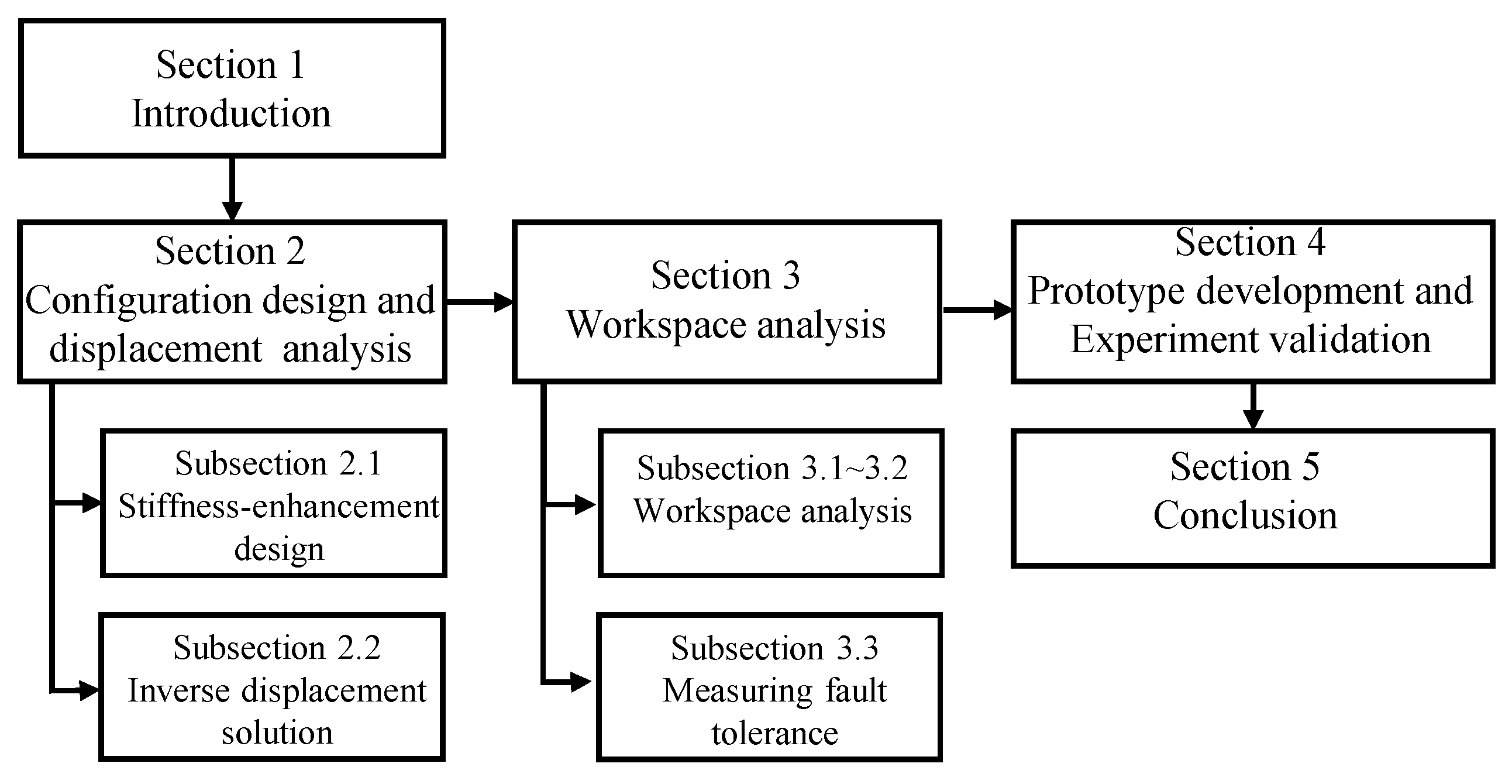
:1. Introduction
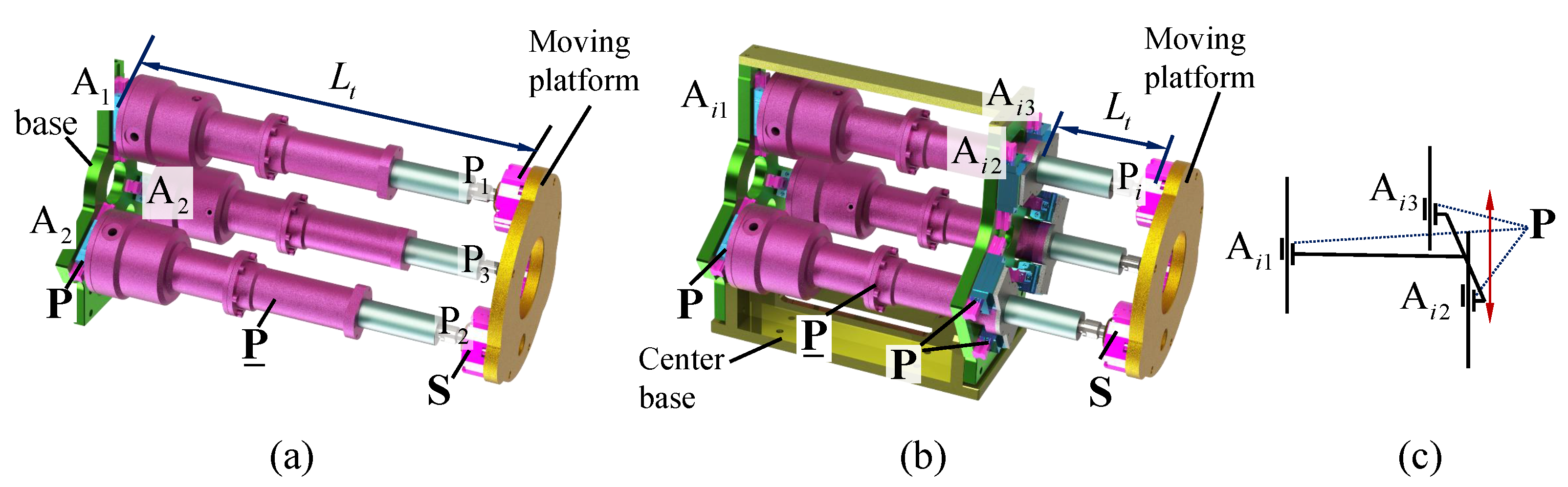
2. Configuration Design and Displacement Analysis
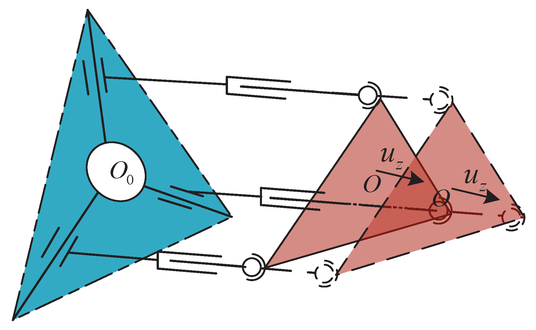
2.1. Stiffness Enhancement Design of a 3-PPS Parallel Mechanism for Underwater Vectored Thrusters
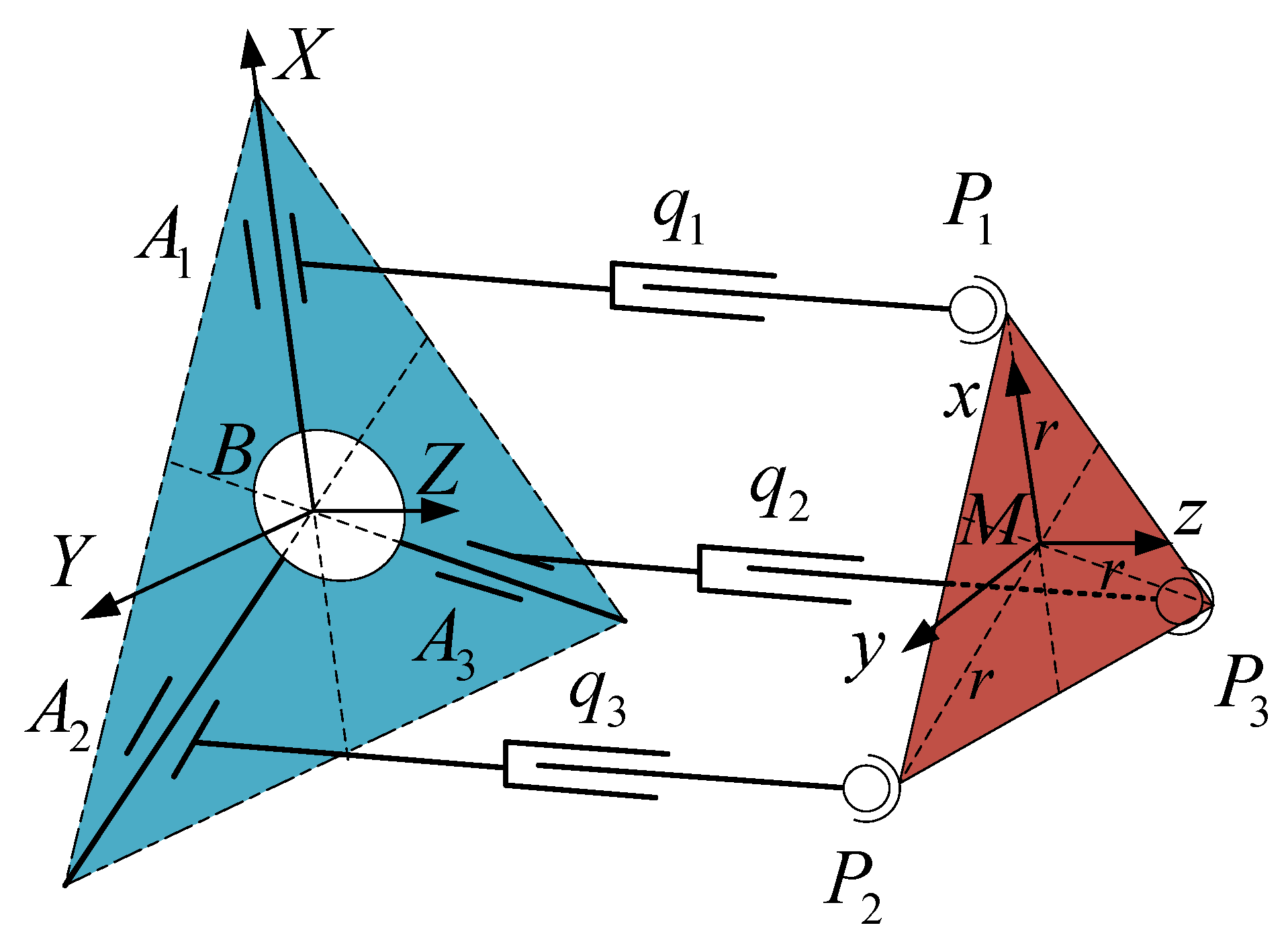
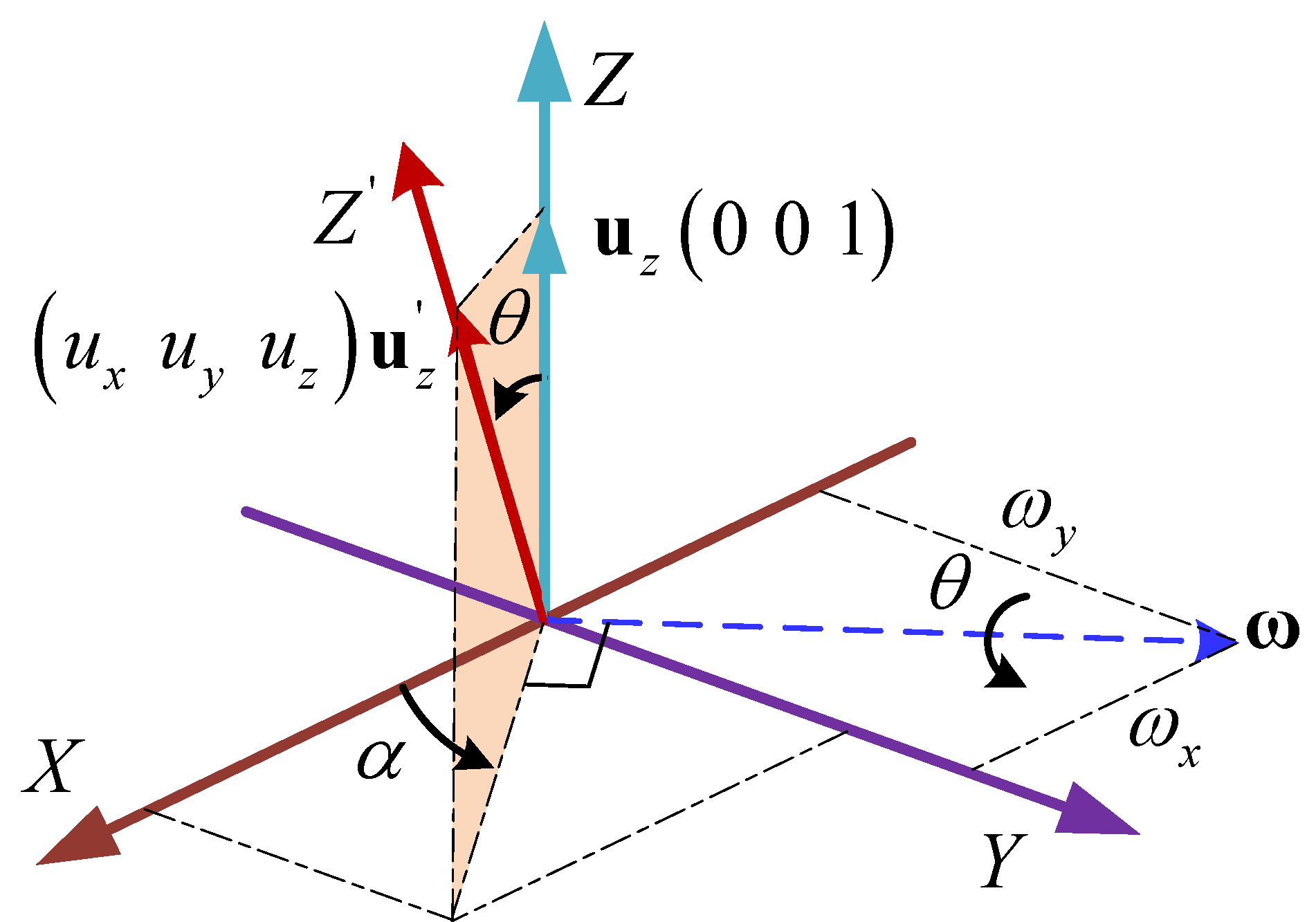
2.2. Displacement Analysis
2.2.1. Inverse Displacement Analysis under Failure-Free Operation
2.2.2. Inverse Displacement Analysis under a Single Actuator Failure
- Define an intermediate variable to determine the value of azimuth angle . When , , . The azimuth angle can be given by:
- When , . In this case, the frame is parallel to the frame , and the moving platform is in instantaneous translation. Thus, the azimuth angle can be set as .
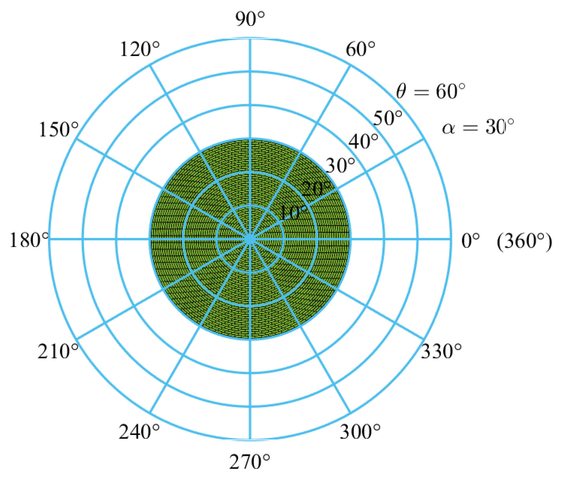
3. Workspace Analysis
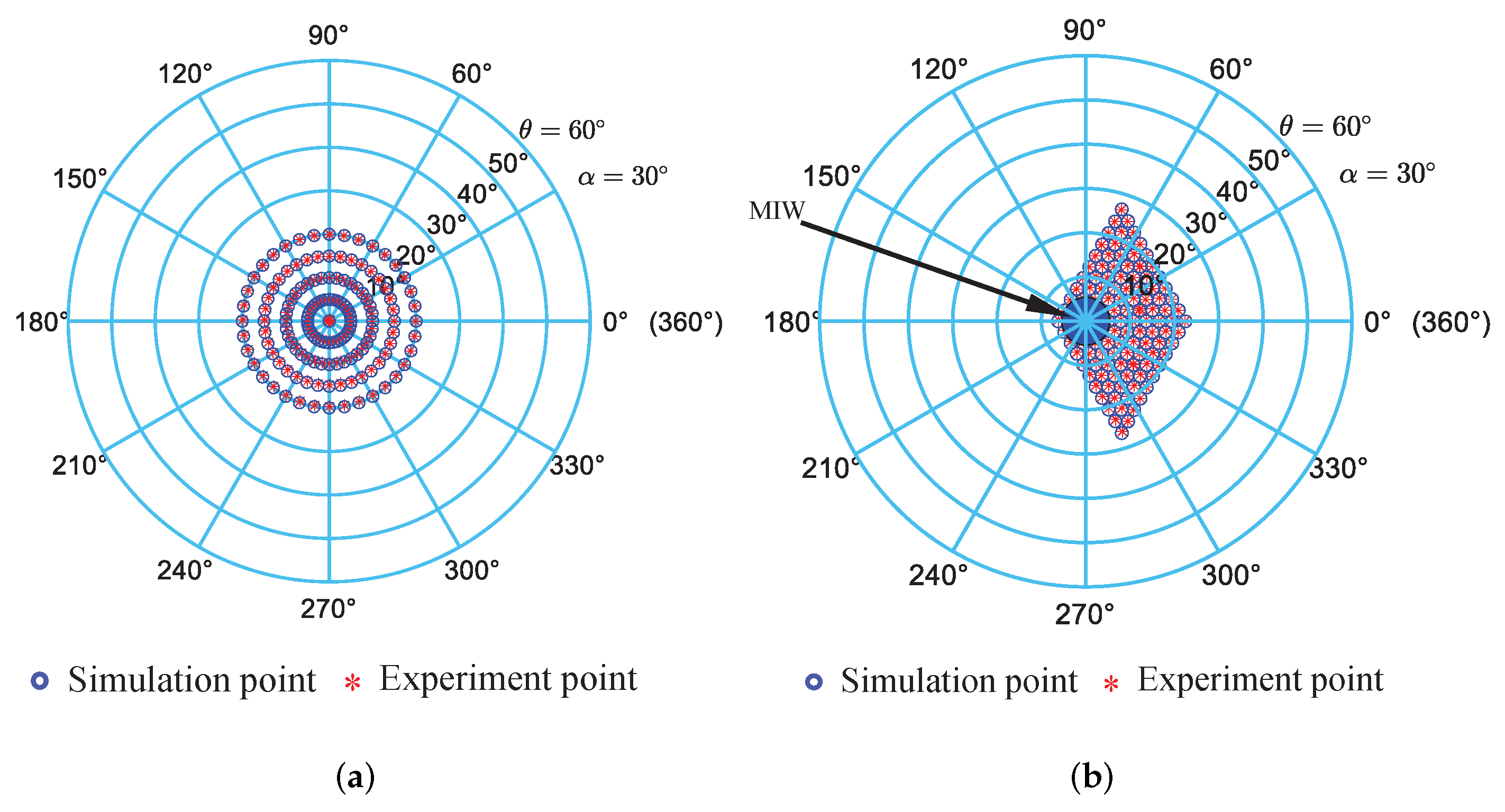
3.1. Workspace Analysis under Failure-Free Operation
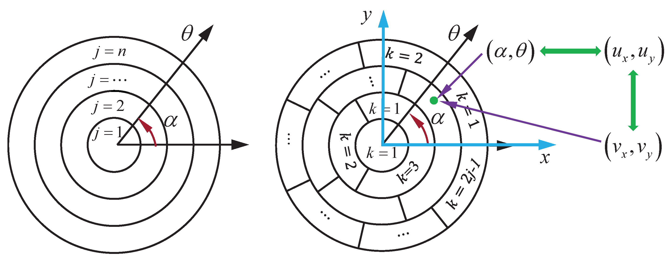
- Step 1:
- Partitioning circular disc into concentric bands
- Step 2:
- Partitioning circular band into elements
3.2. Workspace Analysis under a Single Actuator Failure
3.3. Fault-Tolerant Criterion and Design Based on the Workspace
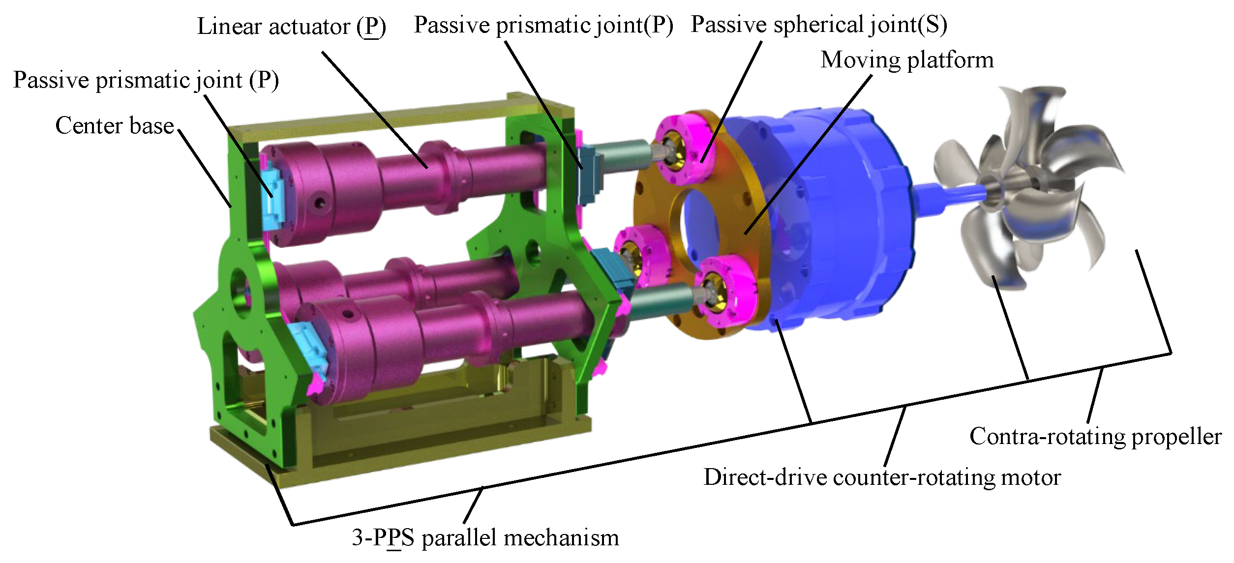
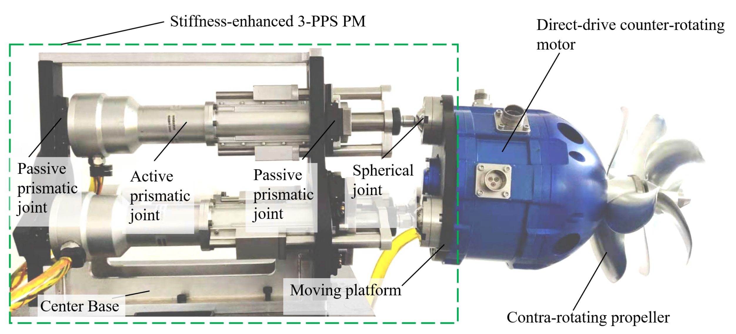
4. Prototype Development and Experimental Validation
4.1. Prototype Development
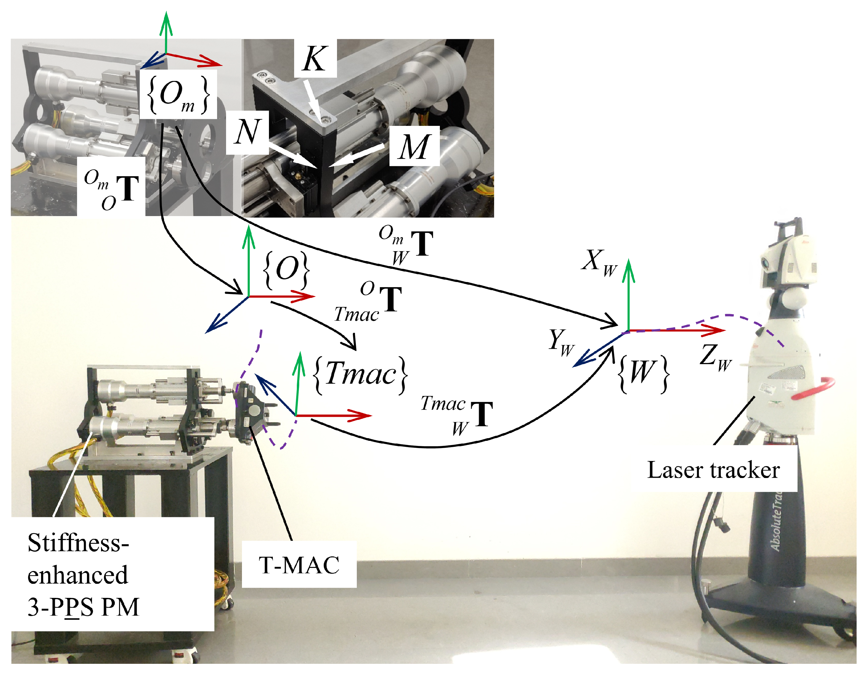
4.2. Experiments Method and Validation
- Step 1:
- Building measurement frame
- Step 2:
- Setting initial orientation
- Step 3:
- Processing measurement data
- Define an intermediate variable to determine the value of azimuth angle , When , . The actual azimuth angle can be given by:
- Step 4:
- Measuring the orientation of the T-MAC
5. Conclusions
Author Contributions
Funding
Institutional Review Board Statement
Informed Consent Statement
Data Availability Statement
Acknowledgments
Conflicts of Interest
References
- Barker, L.D.L.; Jakuba, M.; Bowen, A.D.; German, C.R.; Maksym, T.; Mayer, L.; Boetius, A.; Dutrieux, P.; Whitcomb, L.L. Scientific challenges and present capabilities in underwater robotic vehicle design and navigation for oceanographic exploration under-ice. Remote Sens. 2020, 12, 2588. [Google Scholar] [CrossRef]
- Paull, L.; Saeedi, S.; Seto, M.; Li, H. AUV navigation and localization: A review. IEEE J. Ocean. Eng. 2014, 39, 131–149. [Google Scholar] [CrossRef]
- Cardenas, P.; de Barros, E.A. Estimation of AUV Hydrodynamic Coefficients Using Analytical and System Identification Approaches. IEEE J. Ocean. Eng. 2020, 45, 1157–1176. [Google Scholar] [CrossRef]
- Panda, J.P.; Mitra, A.; Warrior, H.V. A review on the hydrodynamic characteristics of autonomous underwater vehicles. Proc. Inst. Mech. Eng. Part M J. Eng. Marit. Environ. 2021, 235, 15–29. [Google Scholar] [CrossRef]
- Xiu, Y.; Geng, L.; Hu, Z.; Wang, X. Research on underwater fluidic thrust vectoring method based on active flow control technique. In Proceedings of the 2020 5th International Conference on Mechanical, Control and Computer Engineering (ICMCCE), Harbin, China, 25–27 December 2020; pp. 582–587. [Google Scholar]
- Ba, X.; Luo, X.; Shi, Z.; Zhu, Y. A vectored water jet propulsion method for autonomous underwater vehicles. Ocean Eng. 2013, 74, 133–140. [Google Scholar]
- Chao, S.; Guan, G.; Hong, G.-S. Design of a finless torpedo shaped micro AUV with high maneuverability. In Proceedings of the OCEANS 2017—Anchorage, Anchorage, AK, USA, 18–22 September 2017; pp. 1–6. [Google Scholar]
- Saltaren, R.; Aracil, R.; Alvarez, C.; Yime, E.; Sabater, J.M. Field and service applications—Exploring deep sea by teleoperated robot—An Underwater Parallel Robot with High Navigation Capabilities. IEEE Robot. Autom. Mag. 2007, 14, 65–75. [Google Scholar] [CrossRef]
- Jiao, W.; Cheng, L.; Zhang, D.; Zhang, B.; Su, Y. Investigation of Key Parameters for Hydraulic Optimization of an Inlet Duct Based on a Whole Waterjet Propulsion Pump System. Trans. FAMENA 2021, 45, 145–162. [Google Scholar] [CrossRef]
- Gu, S.; Guo, S.; Zheng, L. A highly stable and efficient spherical underwater robot with hybrid propulsion devices. Auton. Robot. 2020, 44, 759–771. [Google Scholar] [CrossRef]
- Wang, R.; Guo, X.; Zhong, S. An Underwater Vector Propulsion Device Based on the RS+2PRS Parallel Mechanism and Its Attitude Control Algorithm. Appl. Sci. 2019, 9, 5210. [Google Scholar] [CrossRef] [Green Version]
- Barack, C.; Condo, A.; Fathauer, K.; Humanchuk, J.; Justice, B.; Limes, N.; Miller, B.; Parekh, P.; Tian, A.; Sender, T.; et al. The Ohio State University Underwater Robotics Puddles AUV Design and Implementation. 2019, p. 7. Available online: https://robonation.org/app/uploads/sites/4/2019/10/OSU_RS19_TDR.pdf (accessed on 20 December 2021).
- Ali, M.A. Spherically Designed Autonomous Underwater Vehicle (AUV). 2020. Available online: https://www.researchgate.net/publication/351713015 (accessed on 20 December 2021).
- Liu, T.; Hu, Y.; Xu, H.; Zhang, Z.; Li, H. Investigation of the vectored thruster AUVs based on 3SPS-S parallel manipulator. Appl. Ocean Res. 2019, 85, 151–161. [Google Scholar] [CrossRef]
- Cavallo, E.; Michelini, R.C.; Filaretov, V.F. Conceptual design of an AUV equipped with a three degrees of freedom vectored thruster. J. Intell. Robot. Syst. 2004, 39, 365–391. [Google Scholar] [CrossRef]
- Zhu, D.; Wang, L.; Hu, Z.; Yang, S.X. A Grasshopper Optimization-based fault-tolerant control algorithm for a human occupied submarine with the multi-thruster system. Ocean Eng. 2021, 242, 110101. [Google Scholar] [CrossRef]
- Jiang, D.; Zheng, T.; Tian, Y.; Li, H.; Zhang, C.; Yang, G. Dynamics Analysis of a Novel Underwater Vectored Thruster Based on 3-PPS Parallel Mechanism. In Proceedings of the 2021 3rd International Symposium on Robotics & Intelligent Manufacturing Technology (ISRIMT 2021), Changzhou, China, 24–26 September 2021; pp. 17–23. [Google Scholar]
- Li, X.; Zhu, D.; Mei, Z.; Jiang, D. Kinematic analysis of 3-RPS parallel mechanism. In Proceedings of the 2017 2nd International Conference on Robotics and Automation Engineering (ICRAE), Shanghai, China, 29–31 December 2017; pp. 183–187. [Google Scholar]
- McInroy, J.E.; O’Brien, J.F.; Neat, G.W. Precise, fault-tolerant pointing using a Stewart platform. IEEE ASME Trans. Mechatron. 1999, 4, 91–95. [Google Scholar] [CrossRef]
- Hassan, M.; Notash, L. Design modification of parallel manipulators for optimum fault tolerance to joint jam. Mech. Mach. Theory 2005, 40, 559–577. [Google Scholar] [CrossRef]
- Schreiber, L.-T.; Gosselin, C. Kinematically redundant planar parallel mechanisms: Kinematics, workspace and trajectory planning. Mech. Mach. Theory 2018, 119, 91–105. [Google Scholar] [CrossRef]
- Hassan, M.; Notash, L. Optimizing fault tolerance to joint jam in the design of parallel robot manipulators. Mech. Mach. Theory 2007, 42, 1401–1417. [Google Scholar] [CrossRef]
- Yi, Y.; McInroy, J.E.; Chen, Y. Fault tolerance of parallel manipulators using task space and kinematic redundancy. IEEE Trans. Robot. 2006, 22, 1017–1021. [Google Scholar]
- Cha, S.-H.; Lasky, T.A.; Velinsky, S.A. Determination of the kinematically redundant active prismatic joint variable ranges of a planar parallel mechanism for singularity-free trajectories. Mech. Mach. Theory 2009, 44, 1032–1044. [Google Scholar] [CrossRef]
- Pazmiño, R.S.; Cena, C.E.G.; Arocha, C.A.; Santonja, R.A. Experiences and results from designing and developing a 6 DoF underwater parallel robot. Robot. Auton. Syst. 2011, 59, 101–112. [Google Scholar] [CrossRef]
- Liu, T.; Hu, Y.; Xu, H.; Wang, Q.; Du, W. A novel vectored thruster based on 3-RPS parallel manipulator for autonomous underwater vehicles. Mech. Mach. Theory 2019, 133, 646–672. [Google Scholar] [CrossRef]
- Bader, A.M.; Maciejewski, A.A. Maximizing the failure-tolerant workspace area for planar redundant robots. Mech. Mach. Theory 2020, 143, 103635. [Google Scholar] [CrossRef]
- Liu, X.-J.; Wang, J.; Oh, K.-K.; Kim, J. A New Approach to the Design of a DELTA Robot with a Desired Workspace. J. Intell. Robot. Syst. 2004, 39, 209–225. [Google Scholar] [CrossRef]
- Yang, G.; Zhu, R.; Fang, Z.; Chen, C.; Zhang, C. Kinematic design of a 2R1T robotic end-effector with flexure joints. IEEE Access 2020, 8, 57204–57213. [Google Scholar] [CrossRef]
- Zhang, D.; Wei, B. Study on the Kinematic Performances and Optimization for Three Types of Parallel Manipulators. Machines 2016, 4, 24. [Google Scholar] [CrossRef] [Green Version]
- Herrero, S.; Pinto, C.; Diez, M.; Corral, J. Analytical Procedure Based on the Matrix Structural Method for the Analysis of the Stiffness of the 2PRU–1PRS Parallel Manipulator. Robotica 2019, 37, 1401–1414. [Google Scholar] [CrossRef]
- Bonev, I.A.; Gosselin, C.M. Analytical determination of the workspace of symmetrical spherical parallel mechanisms. IEEE Trans. Robot. 2006, 22, 1011–1017. [Google Scholar] [CrossRef]
- Ruggiu, M. Position Analysis, Workspace, and Optimization of a 3-PPS Spatial Manipulator. J. Mech. Des. 2009, 131, 051010. [Google Scholar] [CrossRef]
- Yang, G.; Lin, W.; Mustafa, S.K.; Chen, I.; Yeo, S.H. Numerical Orientation Workspace Analysis with Different Parameterization Methods. In Proceedings of the 2006 IEEE International Conference on Mechatronics and Automation, Bangkok, Thailand, 1–3 June 2006; pp. 1–6. [Google Scholar]
- Zhao, J.-S.; Chu, F.; Feng, Z.-J. Symmetrical characteristics of the workspace for spatial parallel mechanisms with symmetric structure. Mech. Mach. Theory 2008, 43, 427–444. [Google Scholar] [CrossRef]
- Murray, R.M.; Li, Z.; Sastry, S.S. A Mathematical Introduction to Robotic Manipulation, 1st ed.; CRC Press: Boca Raton, FL, USA, 1994; ISBN 978-1-315-13637-0. [Google Scholar]


| Specification | Value |
|---|---|
| Maximum tilt angle | 20 |
| Circumcircle radius of the equilateral triangular | 95 mm |
| Root mean square of the fault-tolerant index | 0.2703 |
| Maximum swing angle of spherical joints | 45 |
| Stroke of all limbs | 96 mm |
| Rated payload | 2000 N |
| Repeated orientation accuracy | |
| Maximum operating depth | 4500 m |
| Limb | Displacement | Value (Start:Step:End) |
|---|---|---|
| 15.5 | ||
| 0:7:70 | ||
| 0:7:70 |
Publisher’s Note: MDPI stays neutral with regard to jurisdictional claims in published maps and institutional affiliations. |
© 2022 by the authors. Licensee MDPI, Basel, Switzerland. This article is an open access article distributed under the terms and conditions of the Creative Commons Attribution (CC BY) license (https://creativecommons.org/licenses/by/4.0/).
Share and Cite
Jiang, D.; Zheng, T.; Yang, G.; Tian, Y.; Fang, Z.; Li, H.; Zhang, C.; Ye, H. Design and Analysis of a Stiffness-Enhanced 3-PPS Parallel Mechanism for Fault-Tolerant Underwater Vectored Thrusters. Machines 2022, 10, 88. https://doi.org/10.3390/machines10020088
Jiang D, Zheng T, Yang G, Tian Y, Fang Z, Li H, Zhang C, Ye H. Design and Analysis of a Stiffness-Enhanced 3-PPS Parallel Mechanism for Fault-Tolerant Underwater Vectored Thrusters. Machines. 2022; 10(2):88. https://doi.org/10.3390/machines10020088
Chicago/Turabian StyleJiang, Dexin, Tianjiang Zheng, Guilin Yang, Yingzhong Tian, Zaojun Fang, Huamin Li, Chi Zhang, and Hongwu Ye. 2022. "Design and Analysis of a Stiffness-Enhanced 3-PPS Parallel Mechanism for Fault-Tolerant Underwater Vectored Thrusters" Machines 10, no. 2: 88. https://doi.org/10.3390/machines10020088