
Modeling and Experimental Investigation of U-R Relationship of AA6061-T6 Tubes Manufactured via Free Bending Forming Process

 , , ,
, , ,  and
and
Abstract
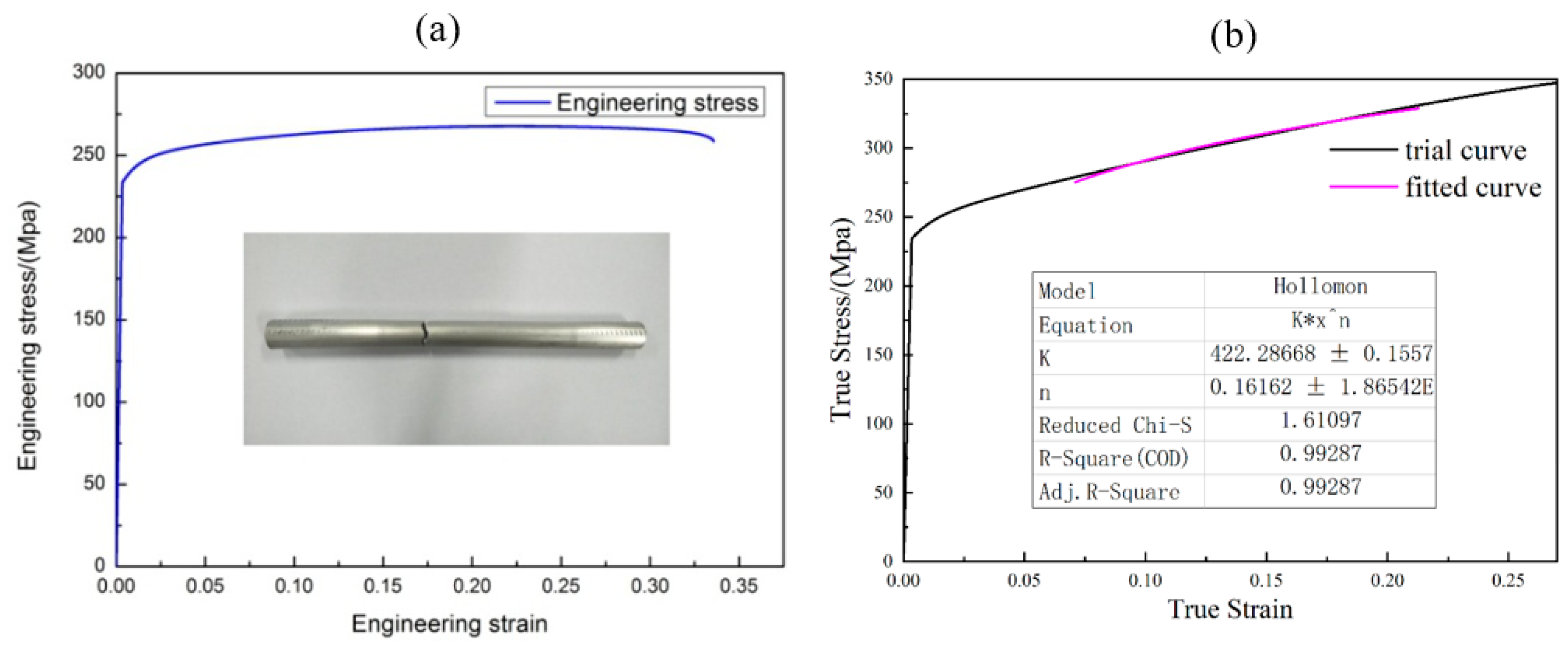
:1. Introduction
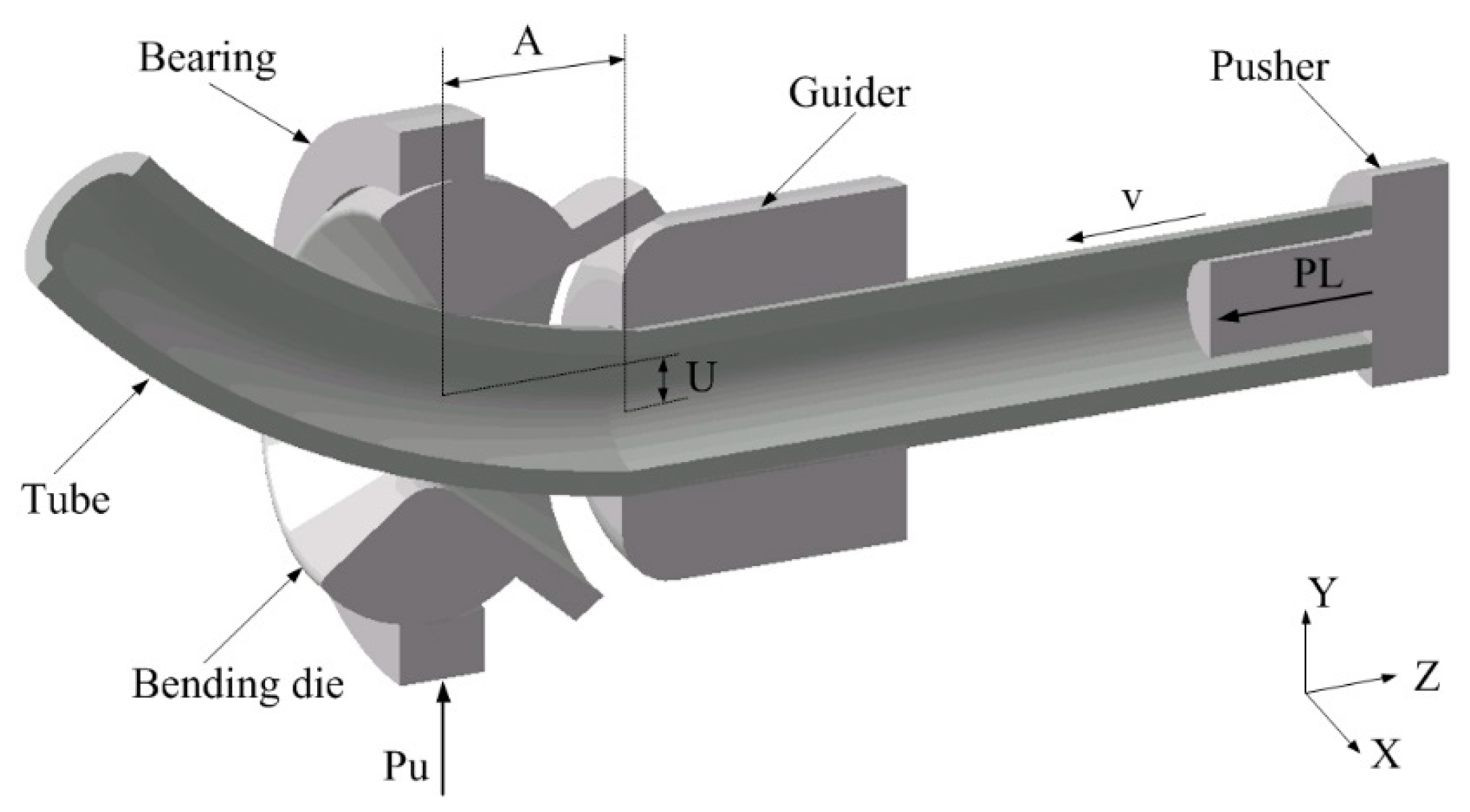
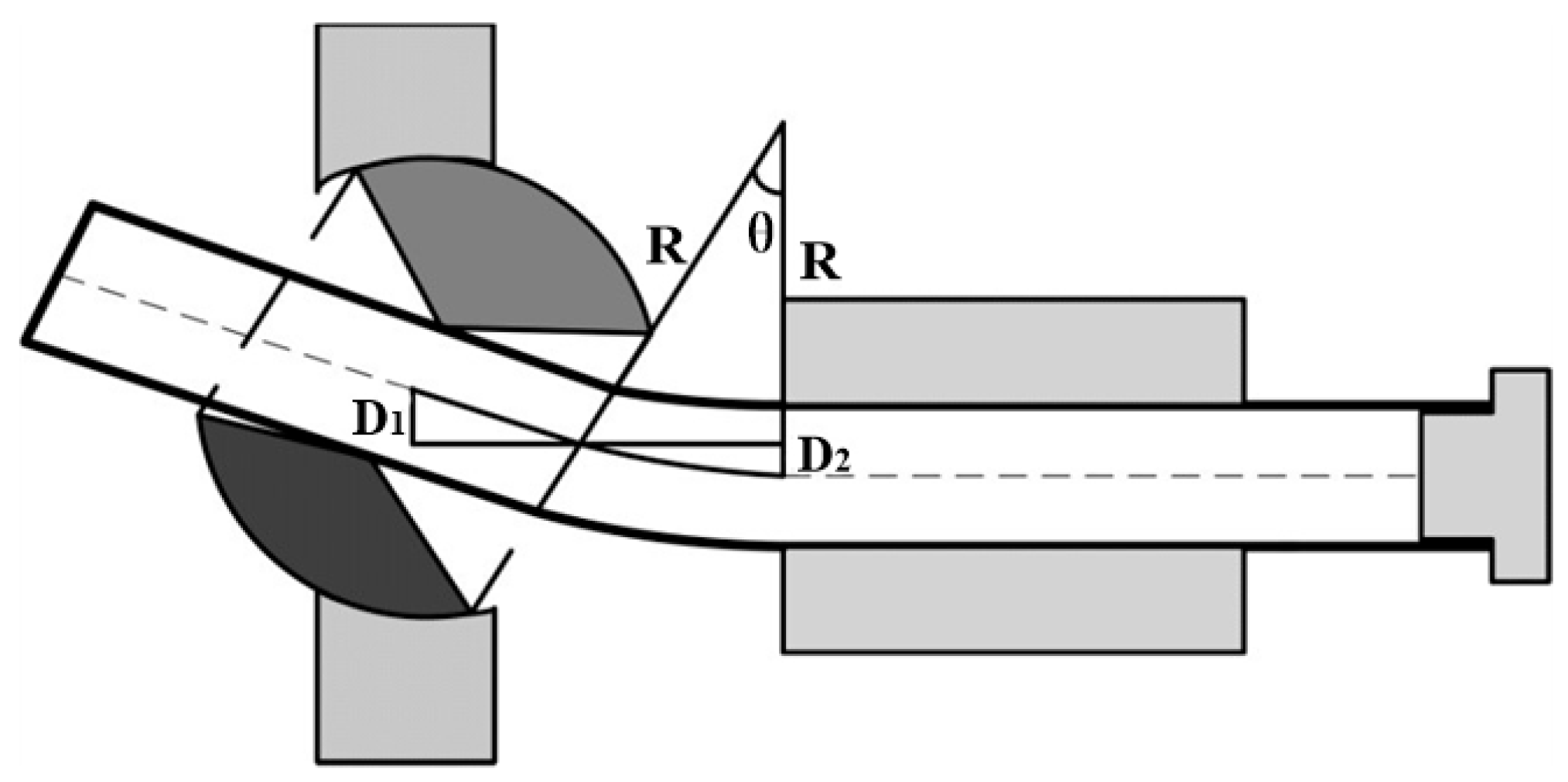
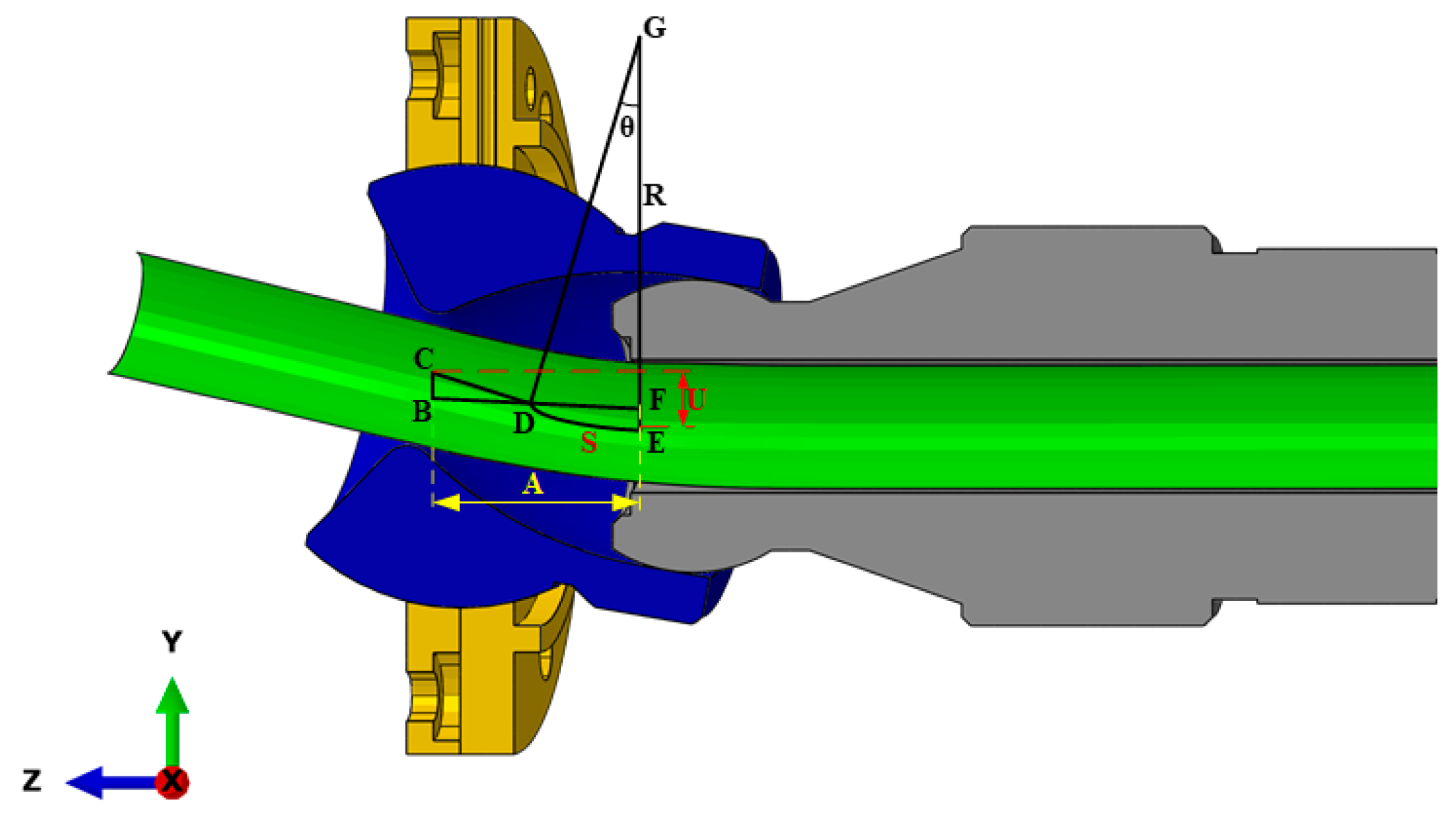
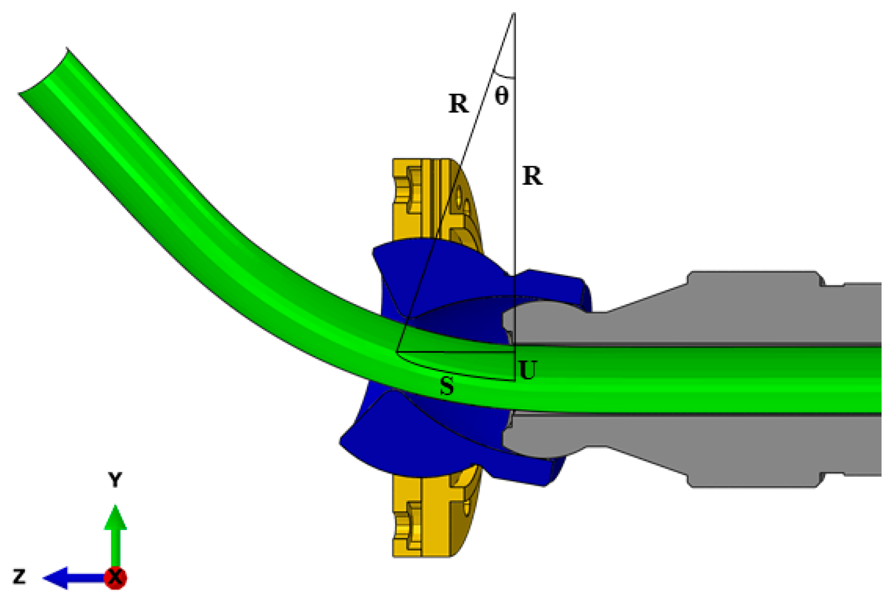
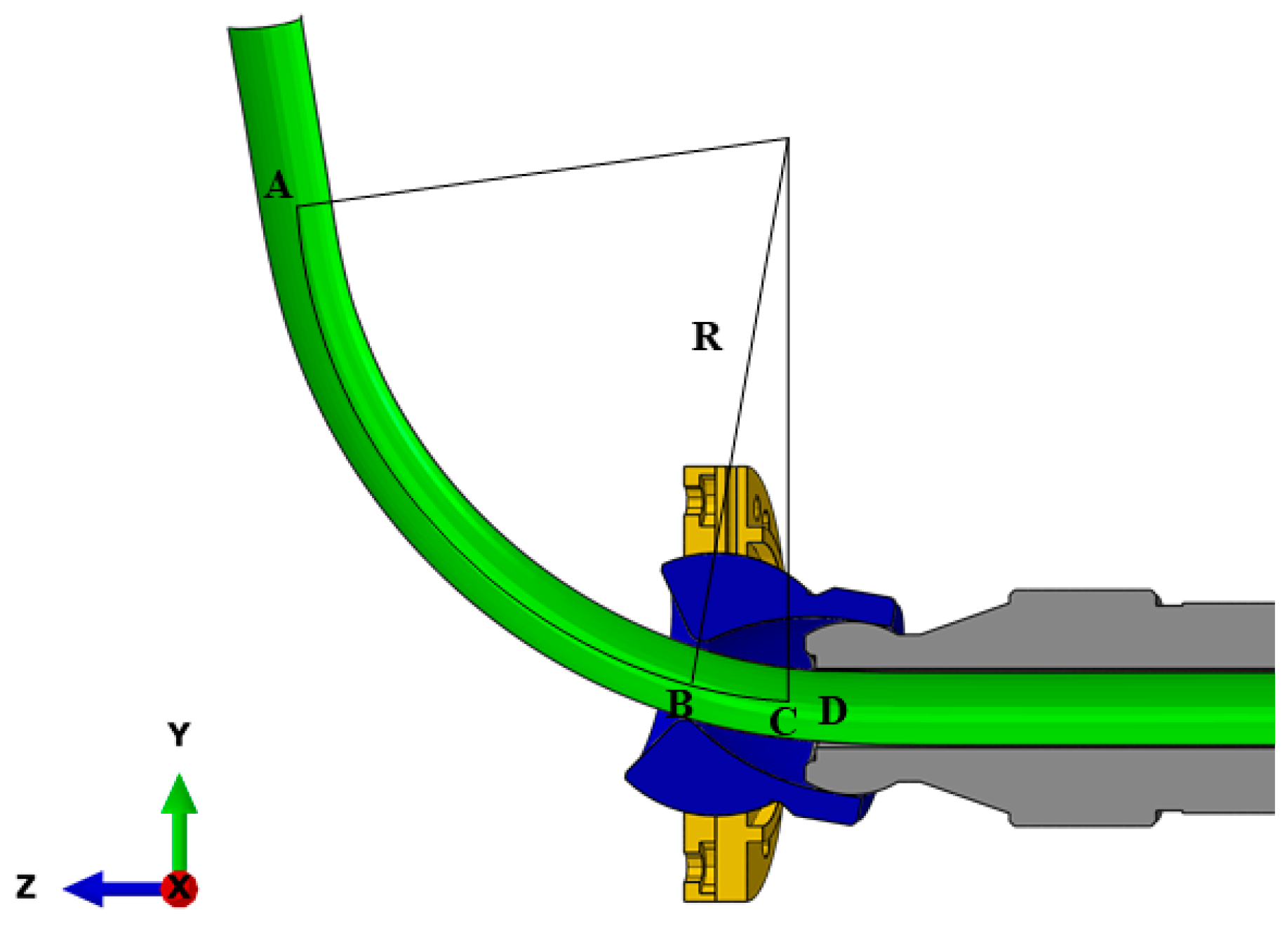
2. U-R Relationship Obtained by the FBF Process
3. Modification of the U-R Mathematical Formula
4. Verification of the Proposed U-R Relationship via FE Modeling and Experimentation
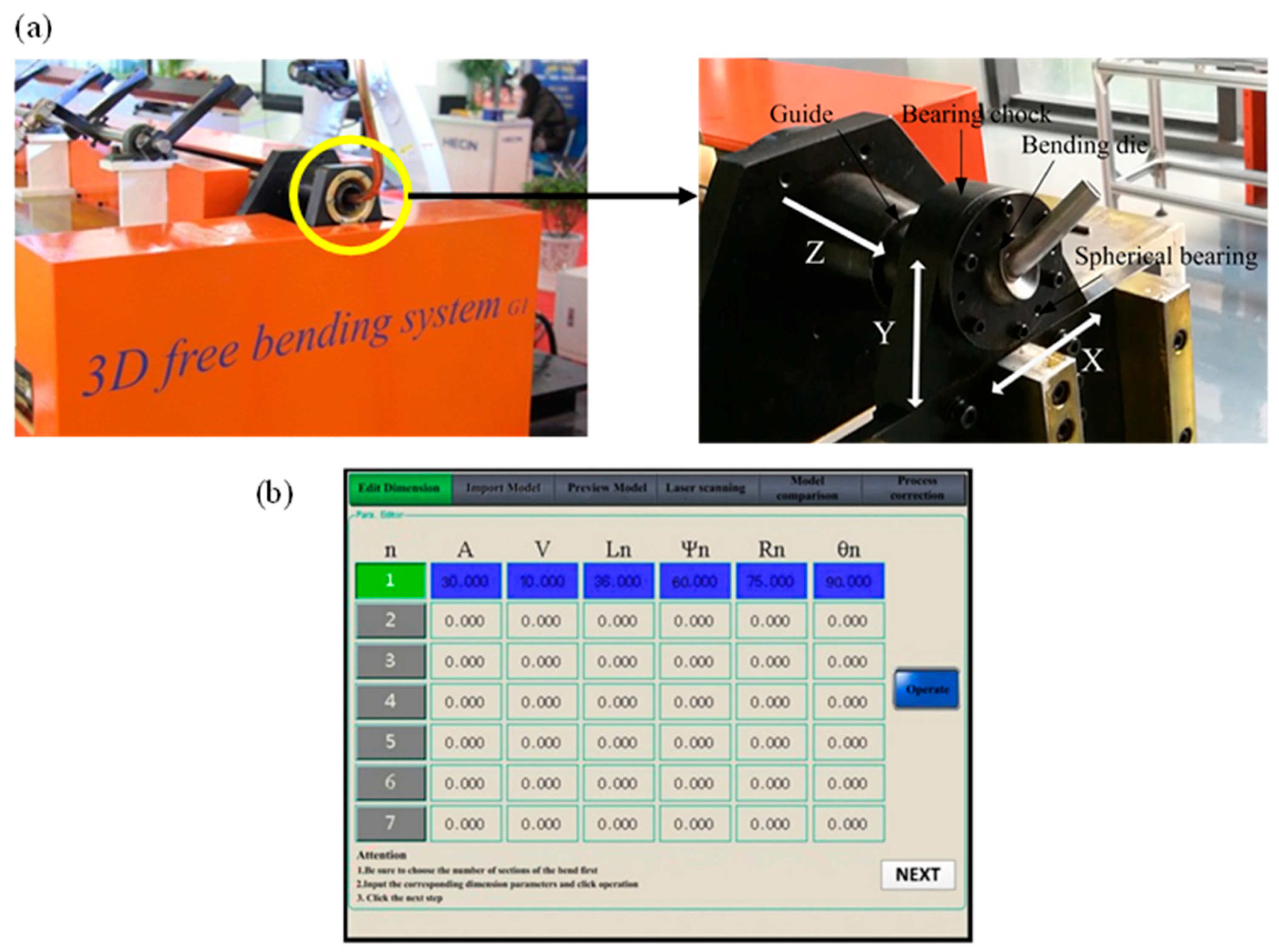
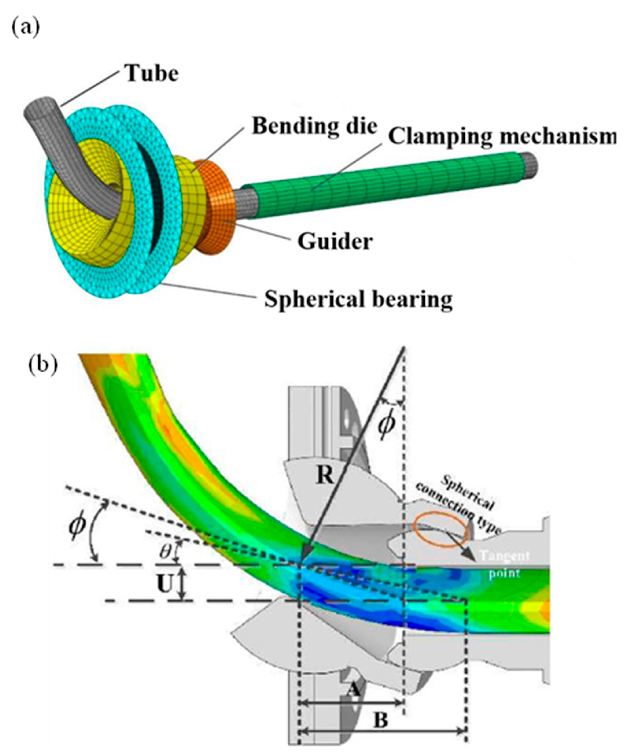
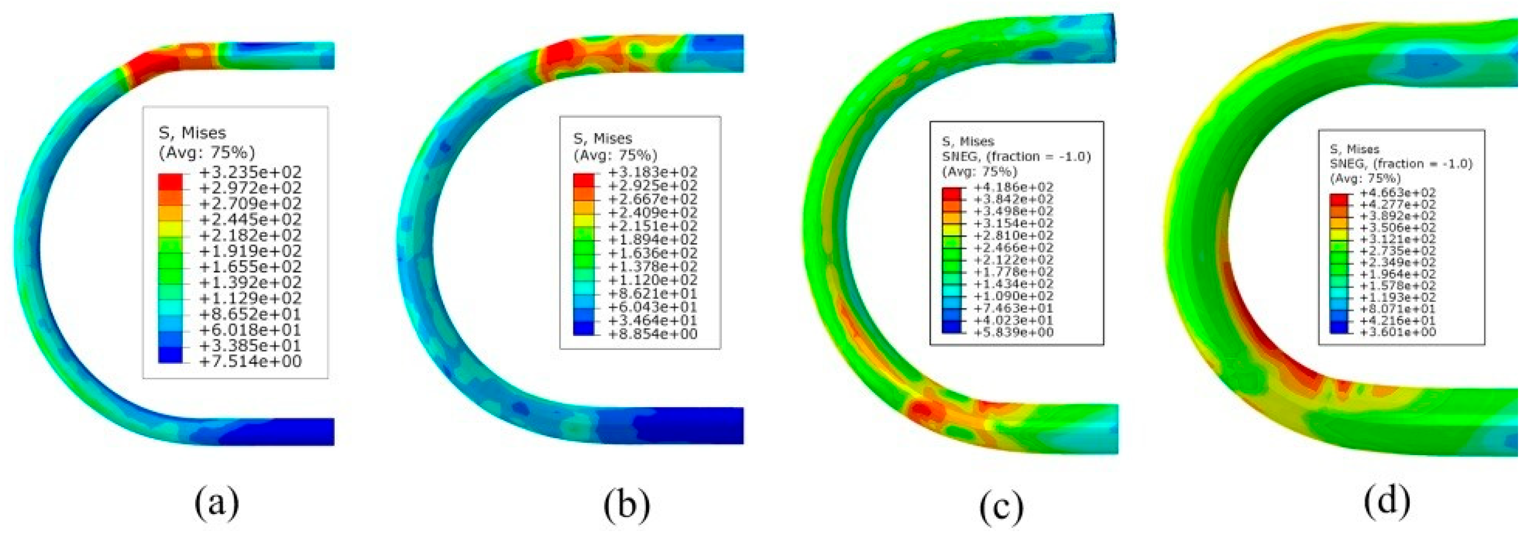
4.1. FE Modeling
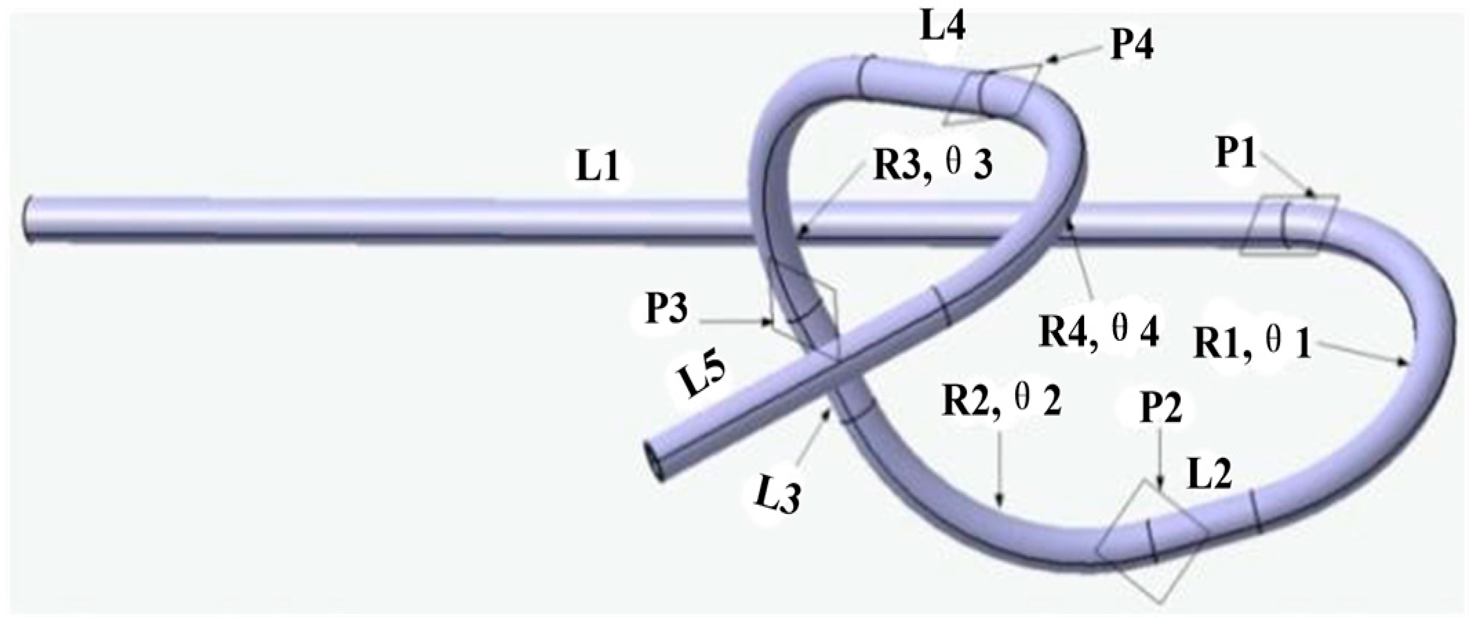
4.2. FBF Experiment of Complex Bend Components
5. Conclusions
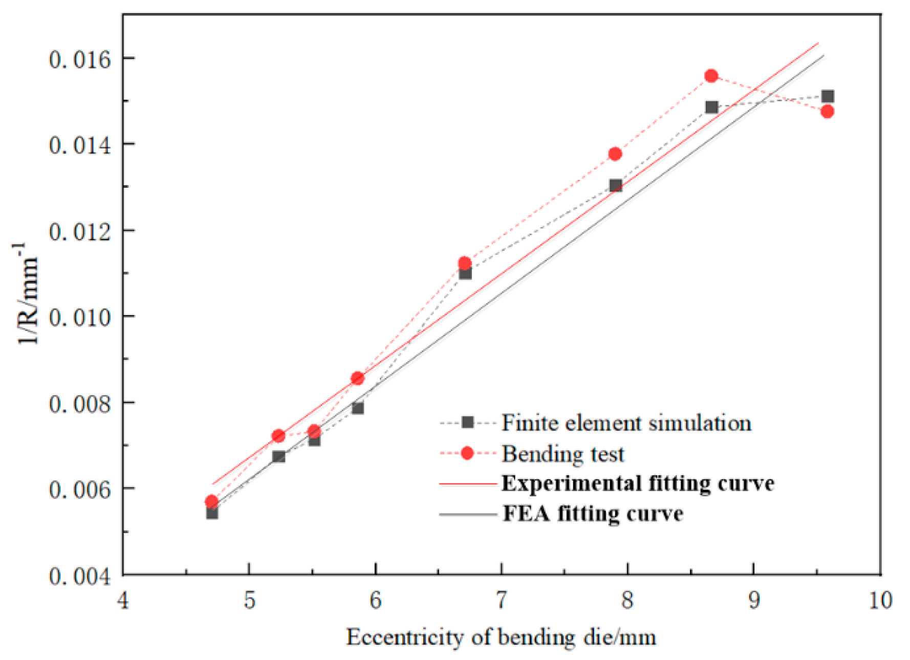
- The modified U-R mathematical formula of the AA6061-T6 Al alloy tube is through the FBF experiment under different eccentricities and certain process conditions.
- The FE simulation result of the U-R relation curve is close to the experimental result, proving that the result shows a good guide for the FBF experiment.
- The FE simulation and the bending experiment were carried out based on the modified U-R relation curve. The results show that the experimental results are in good agreement with the CAD model and the simulation results. The test tube bending radius deviation is relatively small, and the maximum deviation is not more than ±5%, indicating that the U-R relationship of the AA6061-T6 Al alloy tube is accurate and reliable.
- In the ideal forming process, the contact point between the bending die and the tube’s outer bend should remain tangential. However, due to factors such as the bending die clearance and material properties, the rotation angle can be adjusted within a certain range to still ensure smooth tube formation. Deviations from this tangential state, caused by changes in the rotation angle, can lead to overbending or underbending. Thus, it is quite important to propose a new theoretical analysis of the free bending process, taking into account the clearance to analyze the material flow and bending radius changes during nontangential contact between the bending die and the tube. This analysis is crucial to explaining why smooth tube bending is achievable despite rotation angle adjustments and examines the tube’s deformation mechanism under the combined influence of additional tangential force from the bending die and axial propulsive force.
Author Contributions
Funding
Institutional Review Board Statement
Informed Consent Statement
Data Availability Statement
Acknowledgments
Conflicts of Interest
References
- El-Aty, A.A.; Guo, X.; Lee, M.G.; Tao, J.; Hou, Y.; Hu, S.; Li, T.; Wu, C.; Yang, Q. A review on flexibility of free bending forming technology for manufacturing thin-walled complex-shaped metallic tubes. Int. J. Lightweight Mater. Manuf. 2023, 6, 165–188. [Google Scholar] [CrossRef]
- Ma, J.; Li, H.; Fu, M. Modelling of Springback in Tube Bending: A Generalized Analytical Approach. Int. J. Mech. Sci. 2021, 204, 106516. [Google Scholar] [CrossRef]
- Huang, T.; Wang, K.; Zhan, M.; Guo, J.; Chen, X.; Chen, F.; Song, K. Wall Thinning Characteristics of Ti-3Al-2.5V Tube in Numerical Control Bending Process. J. Shanghai Jiaotong Univ. 2019, 24, 647–653. [Google Scholar] [CrossRef]
- Goto, H.; Tanaka, Y.; Ichiryu, K. 3D. Tube Forming and Applications of a New Bending Machine with Hydraulic Parallel Kinematics. Int. J. Autom. Technol. 2013, 49, 92–98. [Google Scholar] [CrossRef]
- Zhao, F.; He, W.P.; Qin, Z.; Zhang, W. Knowledge-based search Algorithm for Tube Bending Interference Avoidance. Appl. Res. Comput. 2006, 11, 65–67. [Google Scholar]
- Ahn, K.; Lee, K.-H.; Lee, J.-S.; Won, C.; Yoon, J. Analytic springback prediction in cylindrical tube bending for helical tube steam generator. Nucl. Eng. Technol. 2020, 52, 2100–2106. [Google Scholar] [CrossRef]
- Hermes, M.; Staupendahl, D.; Becker, C.; Tekkaya, A.E. Innovative Machine Concepts for 3D Bending of Tubes and Profiles. Key Eng. Mater. 2011, 473, 37–42. [Google Scholar] [CrossRef]
- Tao, H.; Fangfang, Y.; Mei, Z.; Junqing, G.; Xuewen, C.; Fuxiao, C.; Kexing, S. Section Flattening in Numerical Control Bending Process of TA18 High Strength Tube. Rare Met. Mater. Eng. 2021, 47, 2347–2352. [Google Scholar] [CrossRef]
- Chiew, S.P.; Jin, Y.F.; Lee, C.K. Residual stress distribution of roller bending of steel rectangular structural hollow sections ScienceDirect. J. Constr. Steel Res. 2016, 119, 85–97. [Google Scholar] [CrossRef]
- Maier, D.; Stebner, S.; Ismail, A.; Dölz, M.; Lohmann, B.; Münstermann, S.; Volk, W. The influence of freeform bending process parameters on residual stresses for steel tubes. Adv. Ind. Manuf. Eng. 2021, 2, 100047. [Google Scholar] [CrossRef]
- Ma, J.; Welo, T.; Wan, D. The impact of thermo-mechanical processing routes on product quality in integrated aluminium tube bending process. J. Manuf. Process. 2021, 67, 503–512. [Google Scholar] [CrossRef]
- Ismail, A.; Maier, D.; Stebner, S.; Volk, W.; Münstermann, S.; Lohmann, B. A Structure for the Control of Geometry and Properties of a Freeform Bending Process. IFAC Pap. Online 2021, 54, 115–120. [Google Scholar] [CrossRef]
- Ghiotti, A.; Simonetto, E.; Bruschi, S. Insights on tube rotary draw bending with superimposed localized thermal field. CIRP J. Manuf. Sci. Technol. 2021, 33, 30–41. [Google Scholar] [CrossRef]
- Simonetto, E.; Ghiotti, A.; Bruschi, S. Dynamic detection of tubes wrinkling in three roll push bending. Procedia Eng. 2017, 207, 2316–2321. [Google Scholar] [CrossRef]
- Song, H.-W.; Xie, W.; Zhang, S.-H.; Jiang, W.; Lăzărescu, L.; Banabic, D. Granular media filler assisted push bending method of thin-walled tubes with small bending radius. Int. J. Mech. Sci. 2021, 198, 106365. [Google Scholar] [CrossRef]
- Zhan, M.; Wang, Y.; Yang, H.; Long, H. An Analytic Model for Pipe Bending Spring Back Considering Different Parameter Variations of Ti-Alloy Pipes. J. Mater. Process. Technol. 2016, 236, 123–137. [Google Scholar] [CrossRef]
- Murata, M.; Kuboki, T. CNC tube forming method for manufacturing flexibly and 3-dimensionally bent tubes. In 60 Excellent Inventions in Metal Forming; Springer: Berlin/Heidelberg, Germany, 2015; pp. 363–368. [Google Scholar] [CrossRef]
- Guo, X.; Xiong, H.; Xu, Y.; El-Aty, A.A.; Ma, Y.; Zhao, Y.; Zhang, S. U-R relationship prediction method for aluminum alloy circular tube free-bending process based on sensitivity analysis of material parameters. Int. J. Adv. Manuf. Technol. 2018, 99, 1967–1977. [Google Scholar] [CrossRef]
- Groth, S.; Frohn, P.; Engel, B. Product planning system for manufacture-oriented modeling of freeform bend tubes produced by three-roll-push-bending. Procedia Manuf. 2019, 34, 10–18. [Google Scholar] [CrossRef]
- Guo, X.; Ma, Y.; Chen, W.; Xiong, H.; Xu, Y.; El-Aty, A.A.; Jin, K. Simulation and experimental research of the free bending process of a spatial tube. J. Mater. Process. Technol. 2018, 255, 137–149. [Google Scholar] [CrossRef]
- Beulich, N.; Craighero, P.; Volk, W. FEA Simulation of Free-Bending—A Preforming Step in the Hydroforming Process Chain. J. Phys. Conf. Ser. 2017, 896, 012063. [Google Scholar] [CrossRef]
- Zhang, Z.; Wu, J.; Liang, B.; Wang, M.; Yang, J.; Muzamil, M. A new strategy for acquiring the forming parameters of a complex spatial tube product in free bending technology. J. Mater. Process. Technol. 2020, 282, 116662. [Google Scholar] [CrossRef]
- Vatter, P.H.; Plettke, R. Process Model for the Design of Bent 3-dimensional Free-form Geometries for the Three-roll-push-bending Process. Procedia CIRP 2013, 7, 240–245. [Google Scholar] [CrossRef]
- Meng, B.; Wan, M.; Zhao, R.; Zhou, Z.P.; Liu, H.X. Micromanufacturing technologies of compact heat exchangers for hypersonic precooled airbreathing propulsion: A review. Chin. J. Aeronaut. 2021, 34, 79–103. [Google Scholar] [CrossRef]
- Scandola, L.; Maier, D.; Werner, M.K.; Hartmann, C.; Volk, W. Automatic extraction and conversion of the bending line from parametric and discrete data for the free-form bending process. In Numisheet; Springer: Cham, Switzerland, 2022; pp. 813–826. [Google Scholar]
- Zhang, Z.C.; Wu, J.J.; Xu, X.L.; Yang, Z.K.; Wu, W.; Liu, L. Mechanical Modeling of Tube Bending Considering Elastoplastic Evolution of Tube Cross-Section. Materials 2022, 15, 3997. [Google Scholar] [CrossRef]
- Cheng, Z.H.; Li, S.X.; Cheng, C.; Guo, X.Z.; Shi, Y.J.; Shu, S. Investigation on variation characteristics of bent tube axis and determination of bending die motion trajectory in free bending process. Int. J. Adv. Manuf. Technol. 2022, 124, 3371–3389. [Google Scholar] [CrossRef]
- Werner, M.K.; Maier, D.; Scandola, L.; Volk, W. Motion profile calculation for freeform bending with moveable die based on tool parameters. In Proceedings of the 24th International ESFAORM Conference on Material Forming, ESAFORM 2021, Liège, Belgium, 14–16 April 2021. [Google Scholar]
- Yang, H.; Lin, Y. Wrinkling Analysis for Forming Limit of Pipe Bending Processes. J. Mater. Process. Technol. 2004, 152, 363–369. [Google Scholar] [CrossRef]
- He, Y.; Heng, L.; Zhang, Z.; Mei ZH, A.N.; Jing LI, U.; Guangjun, L. Advances and trends on tube bending forming technologies. Chin. J. Aeronaut. 2012, 25, 1–12. [Google Scholar]
- Gantner, P.; Harrison, D.K.; Silva AK, M.D.; Bauer, H. New bending technologies for the automobile manufacturing industry. In Proceedings of the 34th International MATADOR Conference, Manchester, UK, 7–9 July 2004; Springer: London, UK, 2004; pp. 211–216. [Google Scholar]
- Gantner, P.; Bauer, H.; Harrison, D.K.; Silva, A.K. Free-Bending—A new bending technique in the hydroforming process chain. J. Mater. Process. 2005, 167, 302–308. [Google Scholar] [CrossRef]
- Murata, M. Effect of die profile and aluminum circular tube thickness with MOS bending. J. Jpn. Inst. Light Met. 2016, 46, 626–631. [Google Scholar] [CrossRef]
- Murata, M.; Ohashi, N.; Suzuki, H. New flexible penetration bending of a tube: 1st report, a study of MOS bending method. Trans. Jpn. Soc. Mech. Eng. 1989, 55, 2488–2492. [Google Scholar] [CrossRef]
- Li, H.; Yang, H. A study on multi-defect constrained bendability of thin-walled tube NC bending under different clearance. Chin. J. Aeronaut. 2011, 24, 102–112. [Google Scholar] [CrossRef]
- Zhou, Y.P.; Li, P.F.; Li, M.Z.; Wang, L.Y.; Sun, S. Residual stress and springback analysis for 304 stainless steel tubes in flexible-bending process. Int. J. Adv. Manuf. Technol. 2017, 94, 1317–1325. [Google Scholar] [CrossRef]
- Murata, M. Analysis of circular tube bending by MOS bending method. In Proceedings of the 5th International Conference on Technology of Plasticity, ICTP 1996, Columbus, OH, USA, 7–10 October 1996; pp. 505–508. [Google Scholar]
- Li, P.; Wang, L.; Li, M. Flexible-bending of profiles and tubes of continuous varying radii. Int. J. Adv. Manuf. Technol. 2016, 88, 1669–1675. [Google Scholar] [CrossRef]
- Gantner, P. The Characterisation of the Free-Bending Technique. Ph.D. Thesis, Glasgow Caledonian University, Glasgow, UK, 2008. [Google Scholar]
- Wei, W.B.; Wang, H.; Xiong, H.; Cheng, X.; Tao, J.; Guo, X.Z. Research on influencing factors and laws of free-bending forming limit of tube. Int. J. Adv. Manuf. Technol. 2019, 106, 1421–1430. [Google Scholar] [CrossRef]
- Li, P.F.; Wang, L.Y.; Li, M.Z. Flexible-bending of profiles with asymmetric crosssection and elimination of side bending defect. Int. J. Adv. Manuf. Technol. 2016, 87, 2853–2859. [Google Scholar] [CrossRef]
- Hashemi, R.; Niknam, S.A. Flexible bending of rectangular profiles: Numerical and experimental investigations. J. Manuf. Process. 2020, 56, 390–399. [Google Scholar] [CrossRef]
- Kawasumi, S.; Takeda, Y.; Matsuura, D. Precise pipe-bending by 3-RPSR parallel mechanism considering springback and clearances at dies. Trans. Jpn. Soc. Mech. Eng. 2014, 80, 343. [Google Scholar]
- Gantner, P.; Harrison, D.K.; Silva, A.K.D.; Bauer, H. The development of a simulation model and the determination of the die control data for the free-bending technique. Proc. Inst. Mech. Eng. Part B J. Eng. Manuf. 2007, 221, 163–171. [Google Scholar] [CrossRef]
- Gantner, P.; Bauer, H. FEA-simulation of bending processes with LS-DYNA. In Proceedings of the 8th International LS-Dyna Users Conference, Dearborn, MI, USA, 2–4 May 2004; pp. 33–40. [Google Scholar]


| Ingredient | Si | Fe | Cu | Mn | Mg | Cr | Ti | Al |
|---|---|---|---|---|---|---|---|---|
| Content | 0.72 | 0.52 | 0.3 | 0.15 | 1.1 | 0.3 | 0.05 | Balanced |
| Density ρ (g/cm3) | Poisson’s Ratio ν | Uniform Elongation Ratio δ (%) | Young’s Modulus E (GPa) | Yield Stress σs (MPa) | Strength Coefficient k | Hardening Exponent n |
|---|---|---|---|---|---|---|
| 2.75 | 0.33 | 16.59 | 69 | 237.39 | 422.29 | 0.1616 |
| Bending Plane | Straight Length Ln (mm) | Bending Radius Rn (mm) | Bending Angle θn (°) | (°) |
|---|---|---|---|---|
| P1 | 600 | 77.5 | 137 | — |
| P2 | 40 | 71 | 106 | 45 |
| P3 | 40 | 68 | 157 | 45 |
| P4 | 50/120 | 83 | 170 | 45 |
| Bending Radius R/mm | 77.5 | 71 | 68 | 83 |
| Eccentricity of bending die U/mm | 7.89 | 8.46 | 8.76 | 7.49 |
| Actual A value/mm | 34.07 | 33.61 | 33.39 | 34.46 |
| Theoretical formula correction factor k | 1.514 | 1.494 | 1.484 | 1.532 |
| CAD Model | Finite Element Simulation Result | Forming Result |
|---|---|---|
 |  |  |
 |  |  |
| Curved Plane | Straight Length Ln (mm) | Bending Radius Rn (mm) | Bending Angle θn (°) | (°) | Maximum Wall Thickness Thinning Rate/(%) | Maximum Cross-section Distortion Rate/(%) |
|---|---|---|---|---|---|---|
| P1 | — | 81 | 120 | — | 6.57 | 4.45 |
| Deviation/(%) | — | 4.5 | −12.4 | — | — | — |
| P2 | 44 | 73 | 98 | 48 | 8.74 | 3.38 |
| Deviation/(%) | 10 | 2.8 | −7.5 | 6.7 | — | — |
| P3 | 42.5 | 70.5 | 145 | 43 | 7.65 | 4.89 |
| Deviation/(%) | 6.25 | 3.7 | −7.6 | −4.4 | — | — |
| P4 | 53 | 80 | 156 | 46 | 8.21 | 4.14 |
| Deviation/(%) | 6 | −3.6 | −8.2 | 2.2 | — | — |
Disclaimer/Publisher’s Note: The statements, opinions and data contained in all publications are solely those of the individual author(s) and contributor(s) and not of MDPI and/or the editor(s). MDPI and/or the editor(s) disclaim responsibility for any injury to people or property resulting from any ideas, methods, instructions or products referred to in the content. |
© 2023 by the authors. Licensee MDPI, Basel, Switzerland. This article is an open access article distributed under the terms and conditions of the Creative Commons Attribution (CC BY) license (https://creativecommons.org/licenses/by/4.0/).
Share and Cite
Abd El-Aty, A.; Cheng, C.; Xu, Y.; Hou, Y.; Tao, J.; Hu, S.; Alzahrani, B.; Ali, A.; Ahmed, M.M.Z.; Guo, X. Modeling and Experimental Investigation of U-R Relationship of AA6061-T6 Tubes Manufactured via Free Bending Forming Process. Materials 2023, 16, 7385. https://doi.org/10.3390/ma16237385
Abd El-Aty A, Cheng C, Xu Y, Hou Y, Tao J, Hu S, Alzahrani B, Ali A, Ahmed MMZ, Guo X. Modeling and Experimental Investigation of U-R Relationship of AA6061-T6 Tubes Manufactured via Free Bending Forming Process. Materials. 2023; 16(23):7385. https://doi.org/10.3390/ma16237385
Chicago/Turabian StyleAbd El-Aty, Ali, Cheng Cheng, Yong Xu, Yong Hou, Jie Tao, Shenghan Hu, Bandar Alzahrani, Alamry Ali, Mohamed M. Z. Ahmed, and Xunzhong Guo. 2023. "Modeling and Experimental Investigation of U-R Relationship of AA6061-T6 Tubes Manufactured via Free Bending Forming Process" Materials 16, no. 23: 7385. https://doi.org/10.3390/ma16237385