
Thermodynamic and Microstructural Analysis of Lead-Free Machining Aluminium Alloys with Indium and Bismuth Additions

1
Impol 2000, d. d., Partizanska 38, SI-2310 Slovenska Bistrica, Slovenia
2
Faculty of Natural Sciences and Engineering, University of Ljubljana, Aškerčeva Cesta 12, SI-1000 Ljubljana, Slovenia
*
Author to whom correspondence should be addressed.
Materials 2023, 16(18), 6241; https://doi.org/10.3390/ma16186241
Submission received: 23 August 2023
/
Revised: 12 September 2023
/
Accepted: 14 September 2023
/
Published: 16 September 2023
(This article belongs to the Special Issue Advanced Light Metal and Alloys: Preparation, Characterization, and Applications)
Abstract
:The present study comprises an investigation involving thermodynamic analysis, microstructural characterisation, and a comparative examination of the solidification sequence in two different aluminium alloys: EN AW 6026 and EN AW 1370. These alloys were modified through the addition of pure indium and a master alloy consisting of indium and bismuth. The aim of this experiment was to evaluate the potential suitability of indium, either alone or in combination with bismuth, as a substitute for toxic lead in free-machining aluminium alloys. Thermodynamic analysis was carried out using Thermo-Calc TCAL-6 software, supplemented by differential scanning calorimetry (DSC) experiments. The microstructure of these modified alloys was characterised using SEM–EDS analysis. The results provide valuable insights into the formation of different phases and eutectics within the alloys studied. The results represent an important contribution to the development of innovative, lead-free aluminium alloys suitable for machining processes, especially for use in automatic CNC cutting machines. One of the most important findings of this research is the promising suitability of indium as a viable alternative to lead. This potential stems from indium’s ability to avoid interactions with other alloying elements and its tendency to solidify as homogeneously distributed particles with a low melting point. In contrast, the addition of bismuth does not improve the machinability of magnesium-containing aluminium alloys. This is primarily due to their interaction, which leads to the formation of the Mg3Bi2 phase, which solidifies as a eutectic with a high melting point. Consequently, the presence of bismuth appears to have a detrimental effect on the machining properties of the alloy when magnesium is present in the composition.
1. Introduction
The 6XXX series of aluminium alloys are precipitation-hardening alloys known for their moderate strength, favourable strength-to-density ratio, good ductility, weldability, and corrosion resistance. However, machining these alloys can be challenging due to the tendency to form long, continuous strips or curls that may wrap around the workpiece or cutting tool, causing disruptions in the machining process [1,2,3,4]. To address this issue, the 6XXX series includes a specific group of alloys known as free-cutting or free-machining alloys. These alloys are exceptionally suitable for use with automatic CNC cutting machines [5]. They are characterized by containing a small amount of soft and non-abrasive microstructural constituents that facilitate chip breaking [6]. Lead was traditionally the primary alloying element employed to enhance machinability until international guidelines were implemented both in the European Union and globally, restricting the use of lead to a maximum of 0.4 wt.% due to its toxic nature [7,8]. In recent years, even more stringent regulations have come into effect, compelling manufacturers to develop new free-cutting aluminium alloys without lead content. To replace lead in free-machining aluminium alloys, the substitute element should possess similar properties. These include insolubility in the aluminium matrix and the ability to form phases with low melting points and lower hardness compared to the aluminium matrix [9]. According to these criteria, the alloying elements that can serve as lead replacements are tin, bismuth, cadmium, thallium, antimony, indium, selenium, and mercury. While various elements can enhance machinability, the most commonly used alternatives are tin or bismuth individually or combinations of tin and bismuth [10]. Other elements are typically excluded for either economic reasons (e.g., indium) or due to their toxicity (thallium, antimony, selenium, cadmium, and mercury). Due to the generation of frictional heat during machining, the machined zone can reach temperatures as high as 350 °C or even higher. Consequently, the most crucial attribute of a potential replacement element or a combination thereof is the ability to form low melting point phases or eutectics that liquefy or soften below 350 °C. This not only improves chip breaking but also prevents material buildup on the cutting edge [11,12,13]. Over the last two decades, significant research efforts have been directed towards the development of new lead-free aluminium alloys. Numerous research papers have investigated the impact of tin and bismuth additions on the microstructure and machining properties of 6XXX lead-free alloys. Initially, tin appeared to be a promising substitute for lead in the 6XXX series. Unfortunately, the tendency to hot cracking increases significantly with higher tin content [10,14,15,16,17]. Faltus et al. [18] established that the quantity and type of particles formed through the interaction of bismuth and tin are crucial factors affecting the alloy’s machinability and ductility. With a higher magnesium content and a lower Si/Mg ratio, there is more formation of Mg2Sn and Mg3Bi2 phase particles, which reduces ductility and machinability. Conversely, with a higher Si/Mg ratio and a lower magnesium content, more low melting point eutectics are formed, resulting in improved machinability. In one of our previous studies [19], we also discovered that bismuth and tin interact with magnesium to form Mg2Sn, Mg2(Si,Sn), and Mg3Bi2 phases, which decrease the ductility of the EN AW 6060 alloy. Bismuth exhibits a higher affinity to magnesium than to silicon, resulting in the formation of the intermetallic α-Mg3Bi2 phase during solidification. This phase manifests as angular or hexagonal particles within the α-Al crystal grains or as a binary eutectic (α-Al + α-Mg3Bi2) with a high melting point [20].
Some patented alloys incorporate tin, bismuth, and indium as substitutes for lead in various combinations, with the indium content not exceeding 0.4 wt.% [21,22]. In our study, however, we introduced indium into the alloys EN AW 6026 and EN AW 1370 at concentrations of 0.35 wt.% and 1 wt.%, respectively. The objective of this experiment was to assess the potential viability of indium, either alone or in combination with bismuth, as a substitute for toxic lead in free-machining aluminium alloys. This was carried out to investigate whether a low-melting-point phase formed in the microstructure of these alloys (TM < 350 °C) could potentially improve machinability. We also performed detailed thermodynamic analyses and microstructural characterizations to clarify the solidification sequence and microstructure evolution.
2. Materials and Methods
The studied free-machining alloys were made from the commercially produced alloy EN AW 6026 (Impol d.d., Slovenska Bistrica, Slovenia, chemical composition in Table 1), 99.995 wt.% pure indium (supplied by Santech Materials, Changsha, China), and 99.99 wt.% pure bismuth (supplied by Wogen, London, UK). For the alloy containing both elements, we first prepared a master alloy consisting of 65 wt.% bismuth and 35 wt.% indium. This composition was selected based on the Bi–In phase diagram, which indicates the stable formation of the BiIn phase at 109.7 °C [23]. For the comparison of the solidification sequence, a commercially available technically pure aluminium alloy EN AW 1370 (Impol d.d., chemical composition in Table 2) was alloyed with the same proportions of indium and the Bi–In master alloy. The sample designations and the respective content of added alloying elements are outlined in Table 3.
When the temperature in the furnace reached 750 °C, indium or the Bi–In master alloy was introduced. Temperature control was achieved using a K-type thermocouple, so that a constant casting temperature of about 750 °C was maintained during all casting operations. Before casting, the melt was manually stirred for about 1 min to prevent the settling of indium or BiIn phases, which possess significantly higher densities than the base alloy. The casting process itself was conducted within a steel mould. The chemical composition of the alloys was determined using an ARL 4460 OES Thermo Scientific spectrometer (Waltham, MA, USA), except for the indium content, which was analysed via X-ray fluorescence spectroscopy (XRF), utilizing the Precious Metals Database. Microstructural analysis was performed using a Thermo Scientific Quattro S field emission scanning electron microscope (FEG SEM) equipped with an EDS SSD Ultim® Max detector from Oxford Instruments. The electron beam was operated at an accelerating voltage of 15 kV and backscattered electrons were used for imaging. Thermodynamic calculations were carried out using Thermo-Calc software from Thermo-Calc in Stockholm, Sweden, while differential scanning calorimetry was performed using the Netzsch STA 449C Jupiter instrument (Mt. Juliet, TN, USA). These methods were utilized to determine phase equilibria and characteristic solidification temperatures.
3. Results and Discussion
3.1. Chemical Composition of Fabricated Alloys
The chemical composition of all synthesized alloys is listed in Table 4. An indium content of 1.04 wt.% was measured in sample EN AW 1370-In, 0.66 wt.% Bi and 0.37 wt.% In were measured in sample EN AW 1370-BiIn, 1.08 wt.% In was measured in sample EN AW 6026-In, and 0.68 wt.% Bi and 0.32 wt.% In were measured in sample EN AW 6026-BiIn.
3.2. Thermodynamic Calculations
Equilibrium isopleth diagrams and non-equilibrium Scheil–Gulliver solidification models were created using Thermo-Calc software for all synthesised alloys. However, in this article, we present the diagram only for the EN AW 6026-In alloy. These diagrams allow us to identify individual microstructural phases and compare the equilibrium and non-equilibrium states with the actual solidification sequence of the alloy. The Thermo-Calc software calculates these diagrams based on thermodynamic laws, a TCAL-6 database of experimentally determined parameters and the assumption of equilibrium solidification [24]. Table 5 shows the predicted phases for all four alloys. According to all Thermo-Calc calculations, indium is expected not to react with other elements and to be present in its elemental form in the microstructure. A similar prediction is made for bismuth in the alloy EN AW 6026-BiIn. The Thermo-Calc calculations did not predict the formation of the intermetallic phase Mg3Bi2, which formed experimentally in the alloy EN AW 6026 with bismuth addition and in the alloy EN AW 6060 with tin and bismuth addition [19,20].
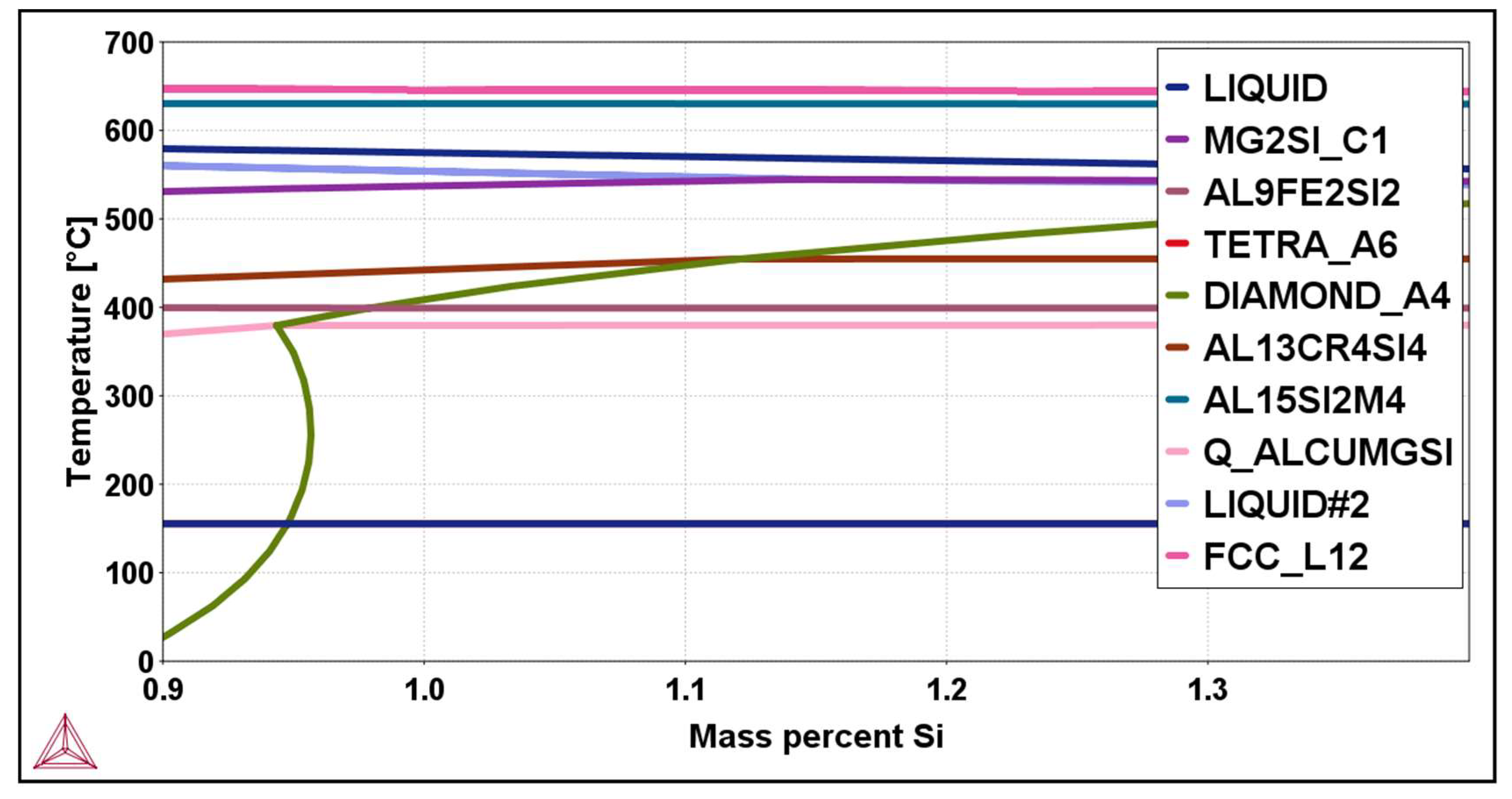
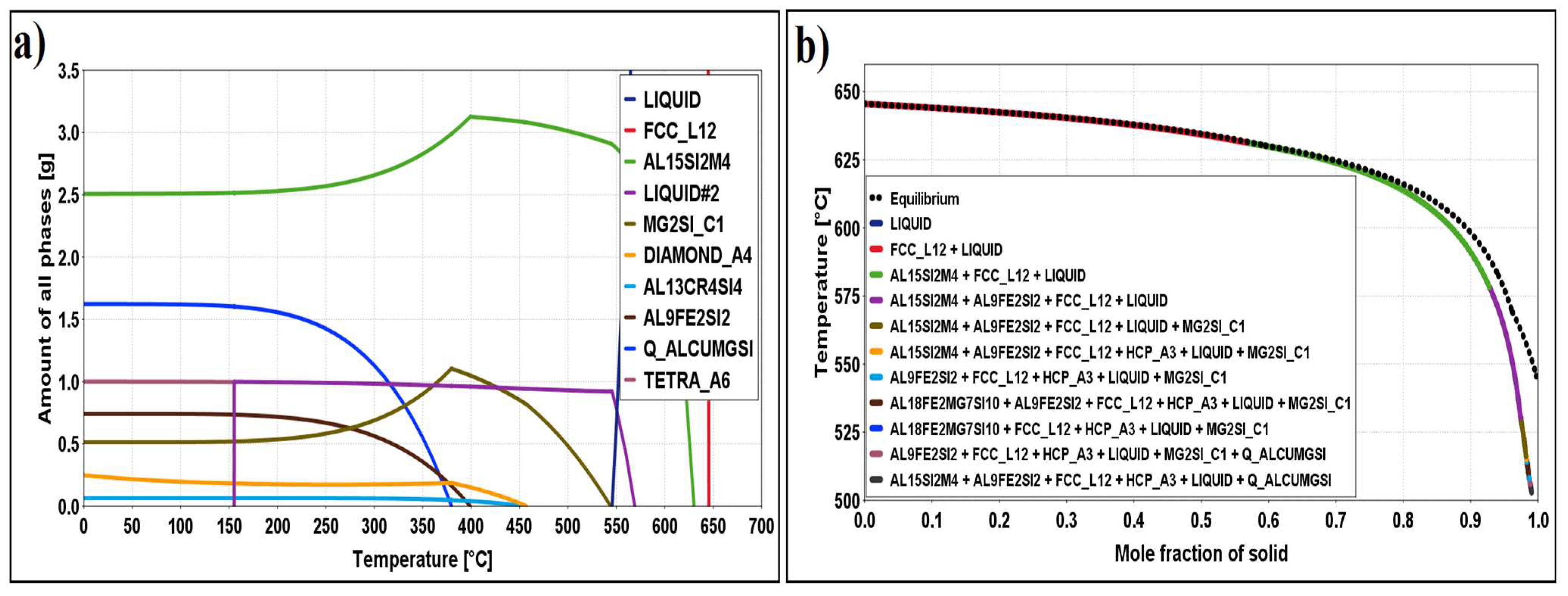
Figure 1 and Figure 2b show the isopleth diagram and the non-equilibrium Scheil–Gulliver diagram for the alloy EN AW 6026-In. The solidification of the alloy starts at a liquidus temperature of 645.4 °C with the solidification of primary α-Al crystals. In the initial phase of solidification, in addition to the primary α-Al crystals, a smaller part of the aluminium melt (LIQUID) rich in indium also appears. The solidification sequence continues with the crystallisation of the phases Al15Si2(Fe,Mn)4, Mg2Si, β-Si, and Al13Cr4Si4. Due to the altered solubility of the elements in the Al15Si2(Fe,Mn)4 and Mg2Si phases, a transformation of the phases occurs at temperatures below 400 °C (Figure 2a), leading to the formation of new phases, such as Al9Fe2Si2 from Al15Si2(Fe,Mn)4 and Al5Cu2Mg8Si6 from Mg2Si.
At a temperature of 155.4 °C, indium finally solidifies from the remaining melt in elemental form. According to the equilibrium diagram, the following phases should be present at room temperature: α-Al, Al13Cr4Si4, Al15Si2(Fe,Mn)4, Al9Fe2Si2, β-Si, Mg2Si, Al5Cu2Mg8Si6, and elemental indium particles. Scheil’s calculation predicts the formation of these phases, with the difference that HCP_A3 is present (Figure 2b). HCP_A3 stands for the interaction between indium and zinc.
3.3. Microstructural Characterization
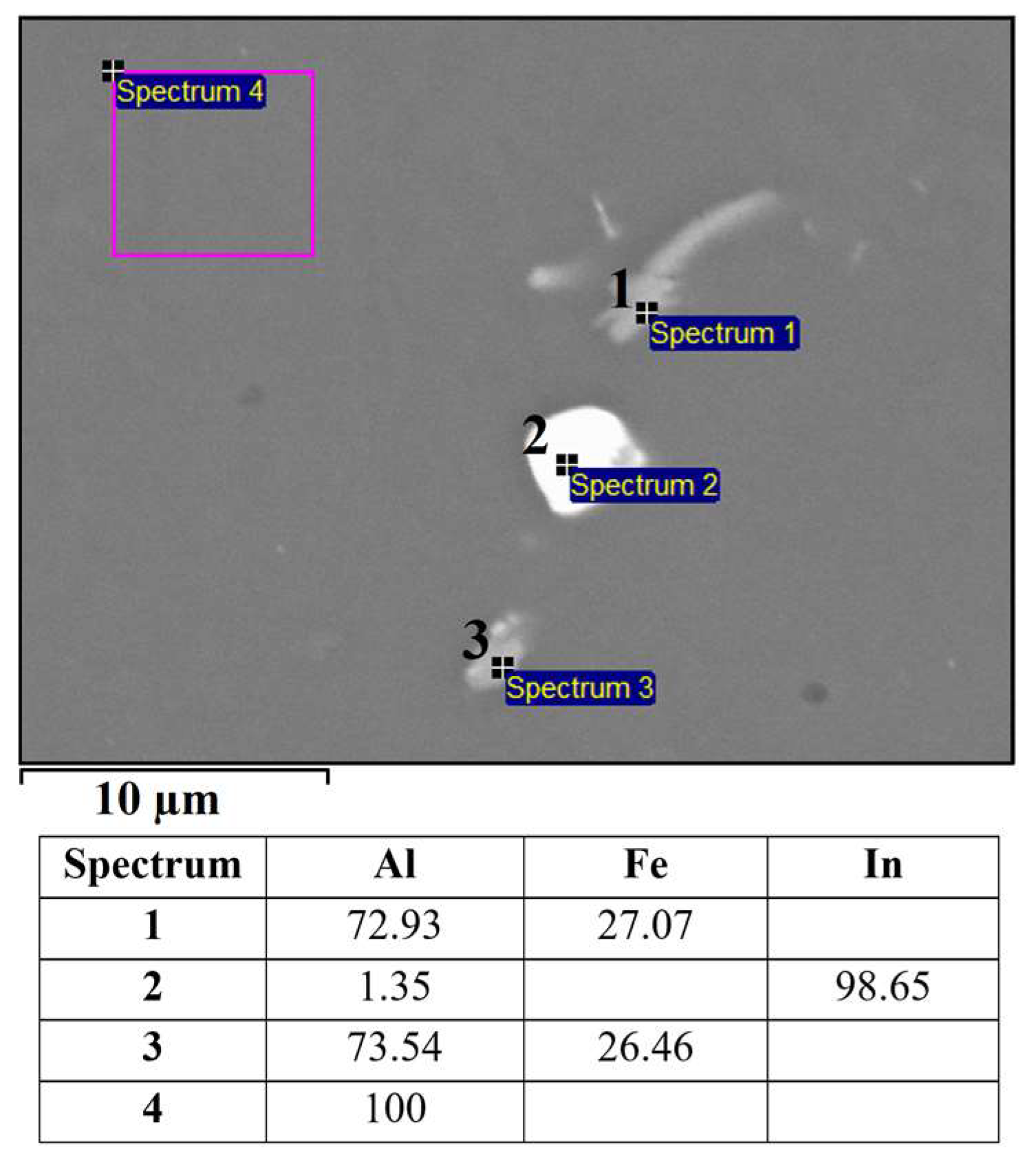
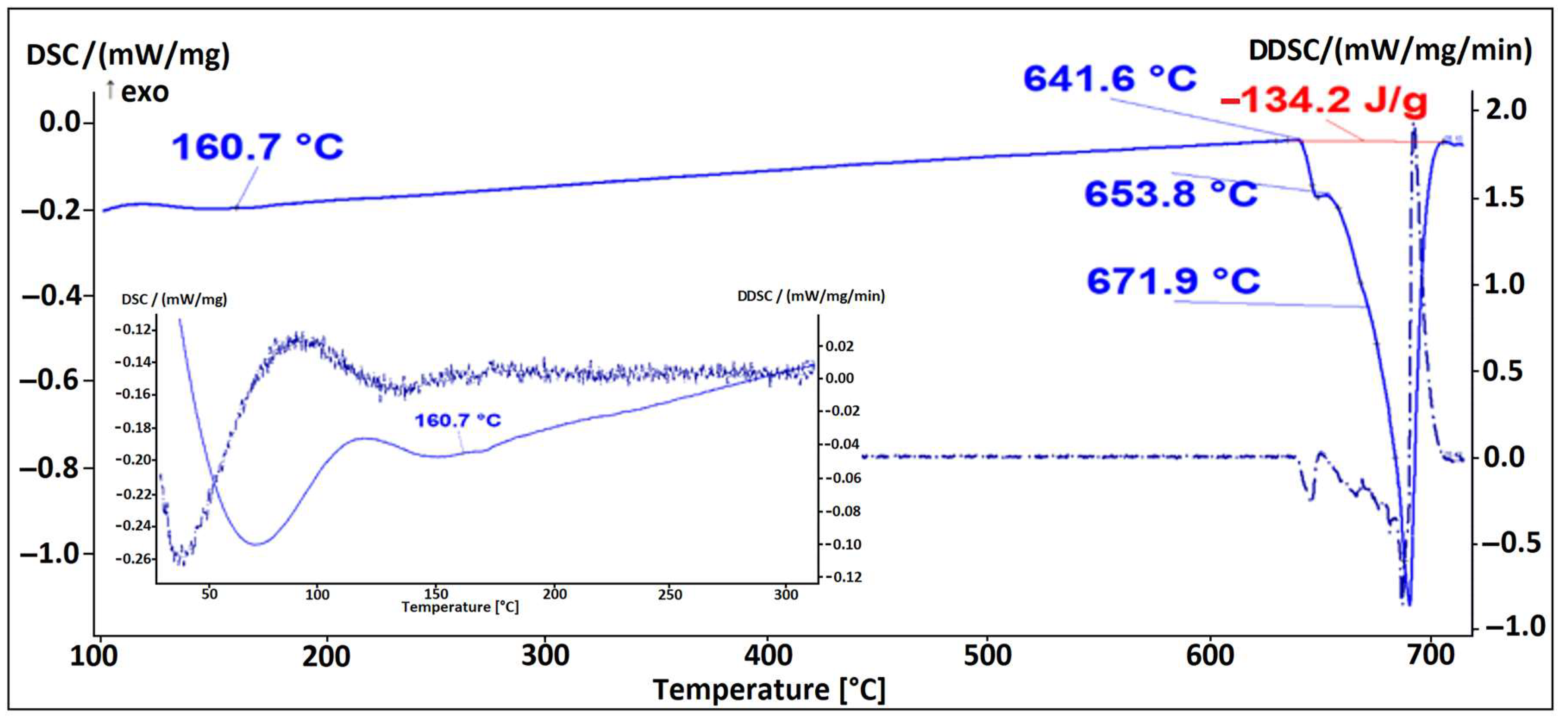
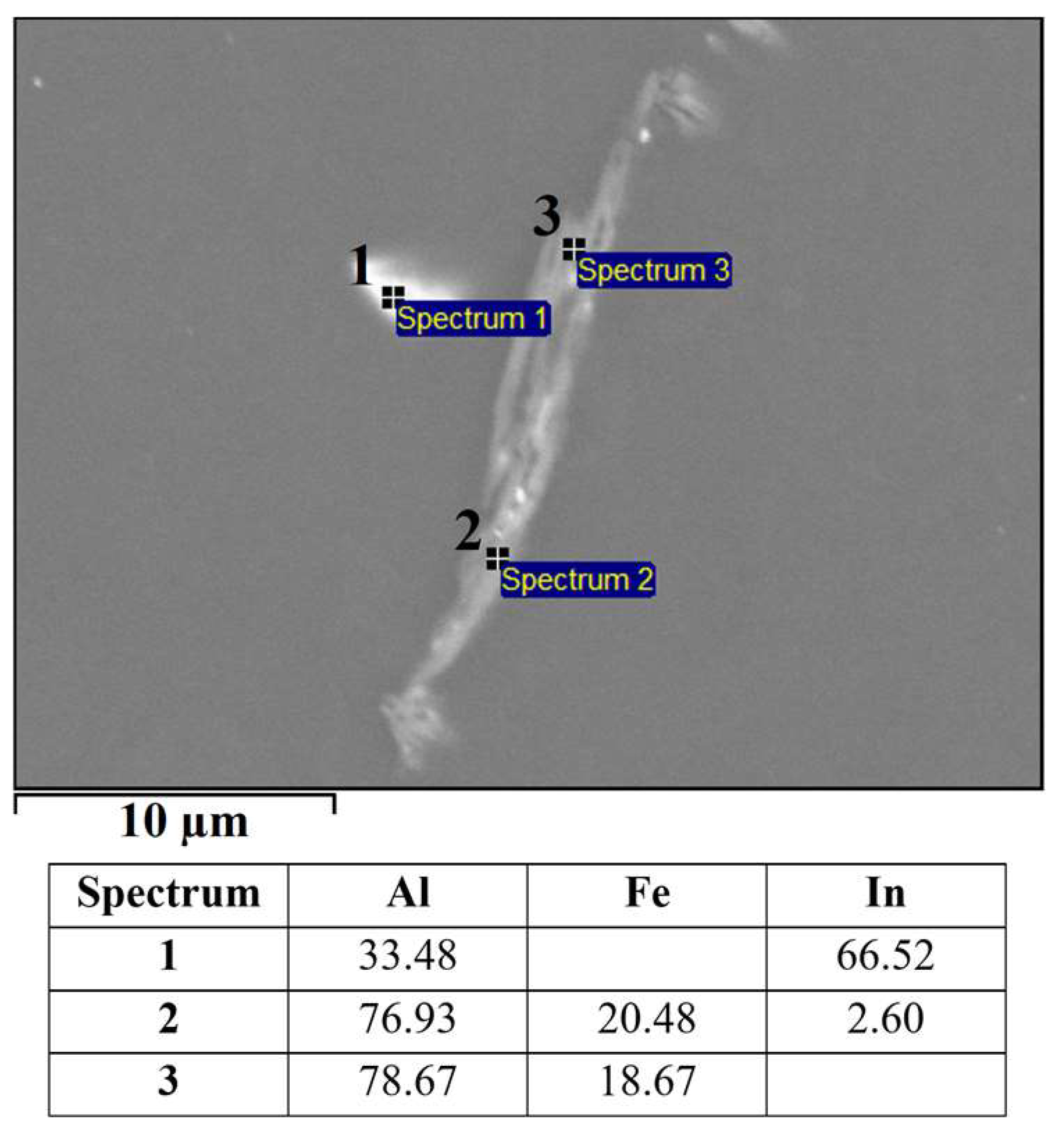
Based on the mass fractions of the individual elements (SEM–EDS, Figure 3) of constituents in the microstructure of the alloy EN AW 1370-In, the presence of α-Al, Al13Fe4 phases, and indium in elemental form (Figure 3, Spectrum 2) can be confirmed. The small amount of aluminium detected via EDS analysis in Spectrum 2 could be due to the excitation of the X-rays by the aluminium matrix due to the interaction volume or contamination of the analysed site with aluminium from the matrix during metallographic sample preparation. The presence of elemental indium particles was further validated through a DSC heating analysis, showing an endothermic peak at a temperature of 160.7 °C, which corresponds to the melting point of pure In (Figure 4). Other endothermic peaks appeared at temperatures 641.6 °C, 653.8 °C, and 671.9 °C. The peaks at 641.8 °C and 653.8 °C are attributed to the melting of the eutectics (α-Al + Al13Fe4 + (Al,In)) and (α-Al + Al13Fe4), respectively. Small indium particles were detected in some Al13Fe4 phases (Figure 5). Scheil’s calculation predicted the formation of a metastable phase BCT_A5 resulting from an interaction between Al and In. The endothermic peak at 641.6 °C observed on the DSC heating curve indicates the presence of a ternary eutectic (α-Al + Al13Fe4 + (Al,In)). The melting point of the α-Al solid solution was determined to be 671.9 °C.
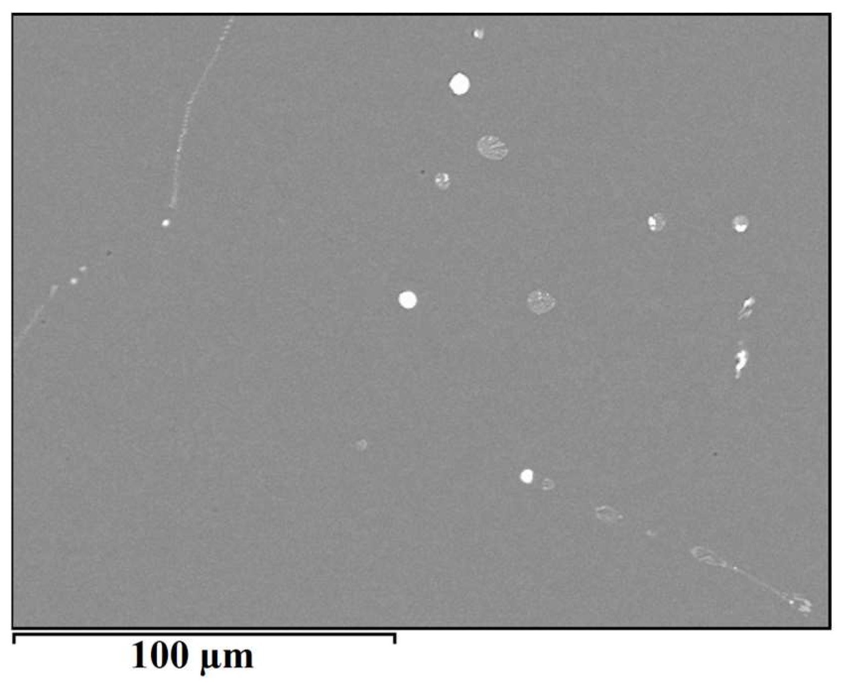
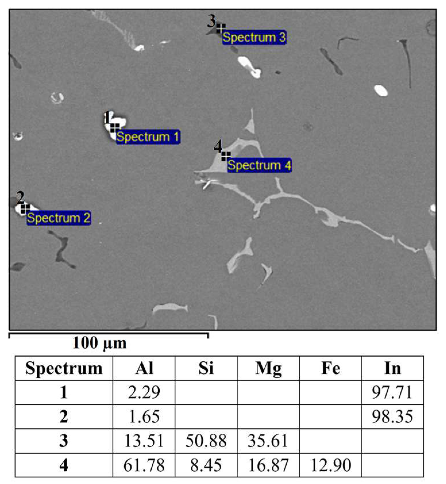
The microstructure of the alloy EN AW 1370-BiIn is shown in Figure 6. Compared to the microstructure of EN AW 1370-In, a higher proportion of spherical eutectics can be observed. From the SEM–EDS analysis, the presence of α-Al, Al13Fe4, and bright BiIn phases in the microstructure is evident (Figure 7).
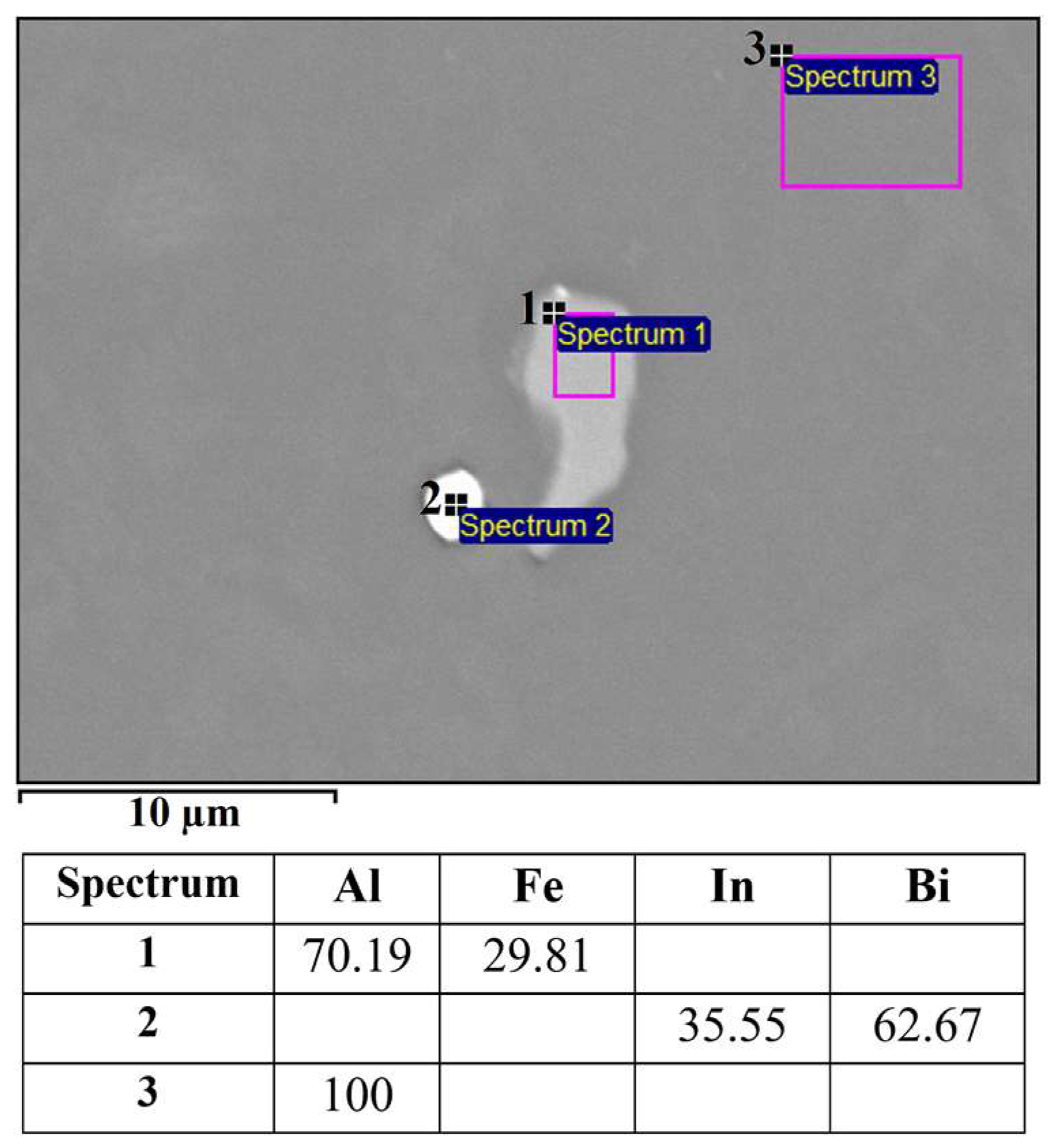
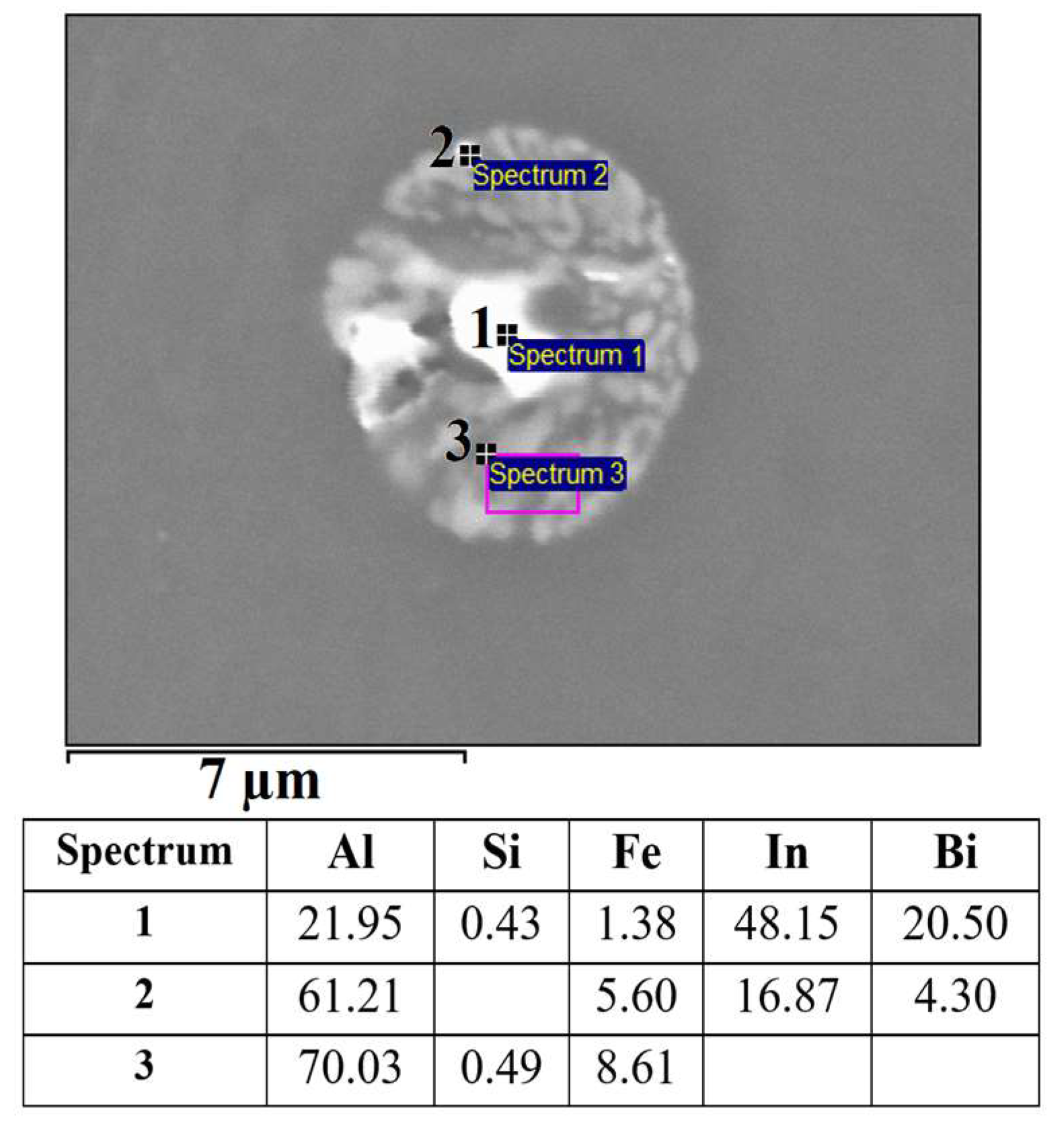
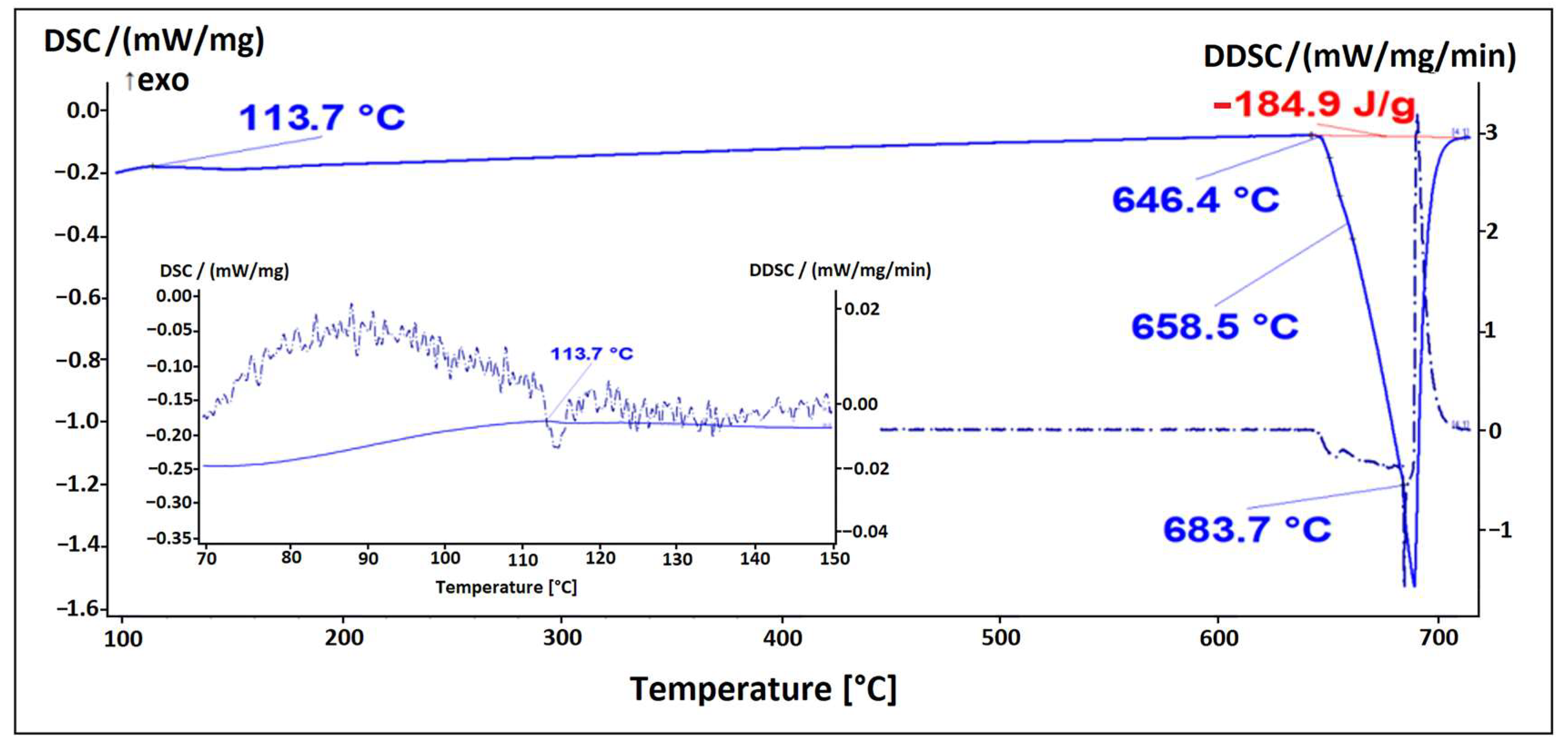
The microstructure of the alloy EN AW 1370-BiIn with marked EDS analysis sites is shown in Figure 7 and Figure 8. The results of the EDS analysis confirm the presence of the Al13Fe4 phase (Figure 7, Spectrum 1) and the BiIn phase (Figure 7, Spectrum 2). The DSC analysis (Figure 9) also detected the endothermic peak at 113.7 °C, which is very close to the BiIn phase melting point (109.7 °C) in the equilibrium Bi–In phase diagram [23]. Figure 8 shows spherical particle consisting of extremely small, bright particles based on Bi, In and Al, combined with Fe and a small amount of Si. According to thermodynamic calculations, the iron phase with Si could be either one of the metastable or stable phases Al8Fe2Si or Al8Fe2Si2 and the phase based on Bi, Al, and In could be the BCT_A5 phase. The combination of these phases with the α-Al phase could form a ternary eutectic (α-Al + Al8Fe2Si + (Al, In, Bi)). The DSC curve (Figure 9) shows clear endothermic peaks at temperatures of 646.4 °C, 658.5 °C, and 683.7 °C. These peaks correspond to the melting of the eutectics (α-Al + Al8Fe2Si + (Al, In, Bi)), (α-Al + Al13Fe4), and α-Al solid solution.
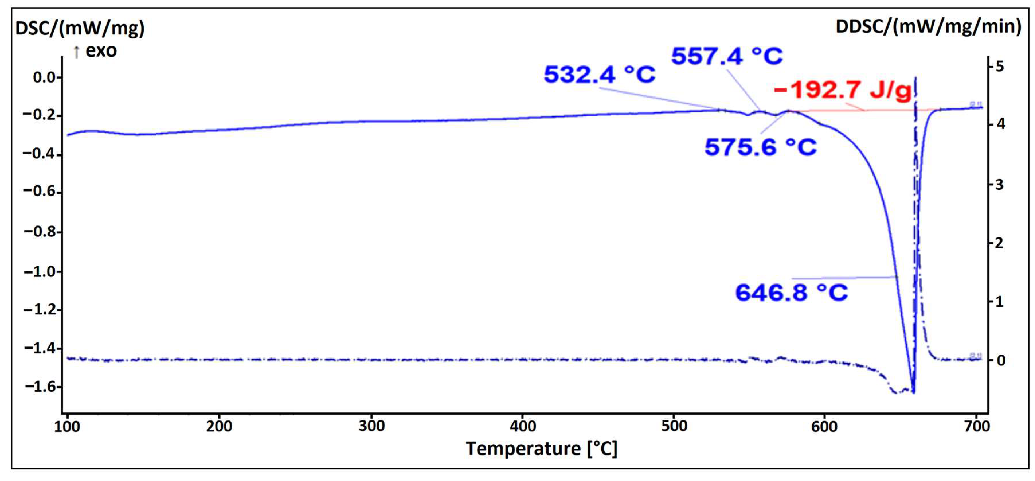
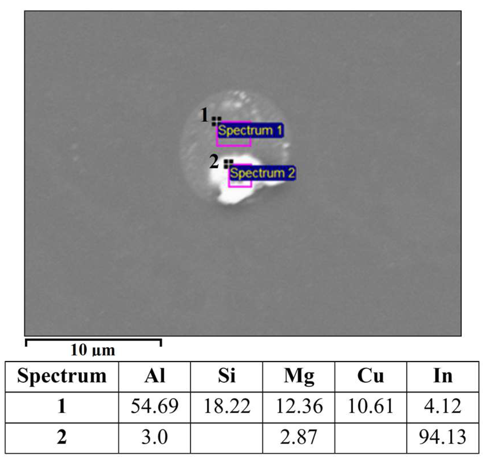
The alloy EN AW 6026 contains magnesium and silicon as the main alloying elements, together with other trace alloying elements such as Fe, Cu, Mn, Cr, Zn, and Ti. Figure 10 shows the microstructure of the alloy EN AW 6026-In. Based on the mass fractions of each element and the Thermo-Calc calculations, we identified the following microstructural constituents in the microstructure: α-Al, Al15Si2(FeMn)3, Mg2Si, Al5Cu2Mg8Si6, and In. The EDS analysis confirmed that indium solidified in elemental form (marked as Spectrum 1 and Spectrum 2 in Figure 10). The low enthalpy of indium resulted in the absence of a prominent endothermic peak on the DSC curve (Figure 11). A spherical eutectic was also observed in the microstructure of the alloy, along with smaller In particles (Figure 12). The EDS analysis detected the presence of Al, Mg, Si, and Cu in the constituents of the spherical particle. Scheil’s calculation and isopleth phase diagram for the alloy EN AW 6026-In predicted the solidification of the Al5Cu2Mg8Si6 phase. Since we detected all listed elements in the EDS spectrum, we assume that this phase is present in the microstructure. On the DSC heating curve, the first prominent endothermic peak was seen at a temperature of 532.4 °C, indicating the melting of the (α-Al + Al5Cu2Mg8Si6) eutectic. Additional endothermic peaks were observed at temperatures of 557.4 °C and 575.6 °C, corresponding to the predicted melting of the (α-Al + Mg2Si) and (α-Al + Al15Si2(FeMn)4) eutectics, respectively. The liquidus temperature of the α-Al solid solution was determined to be 646.8 °C.
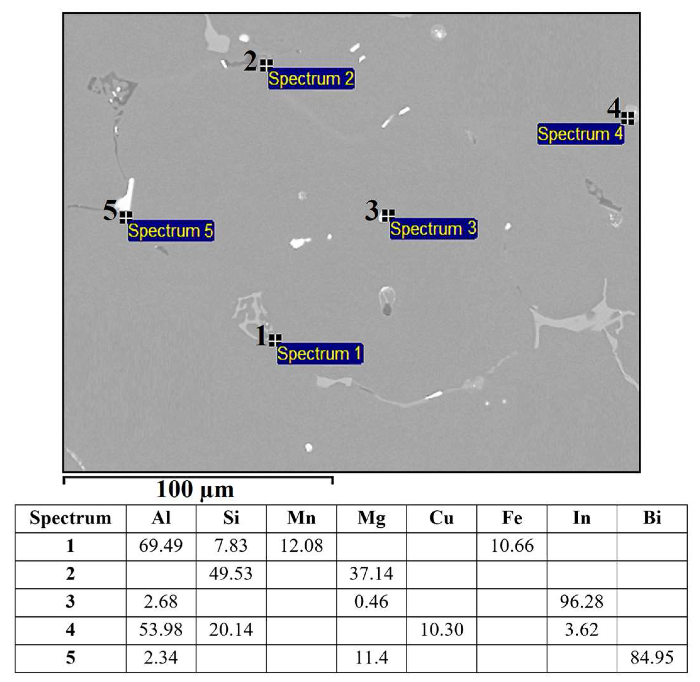
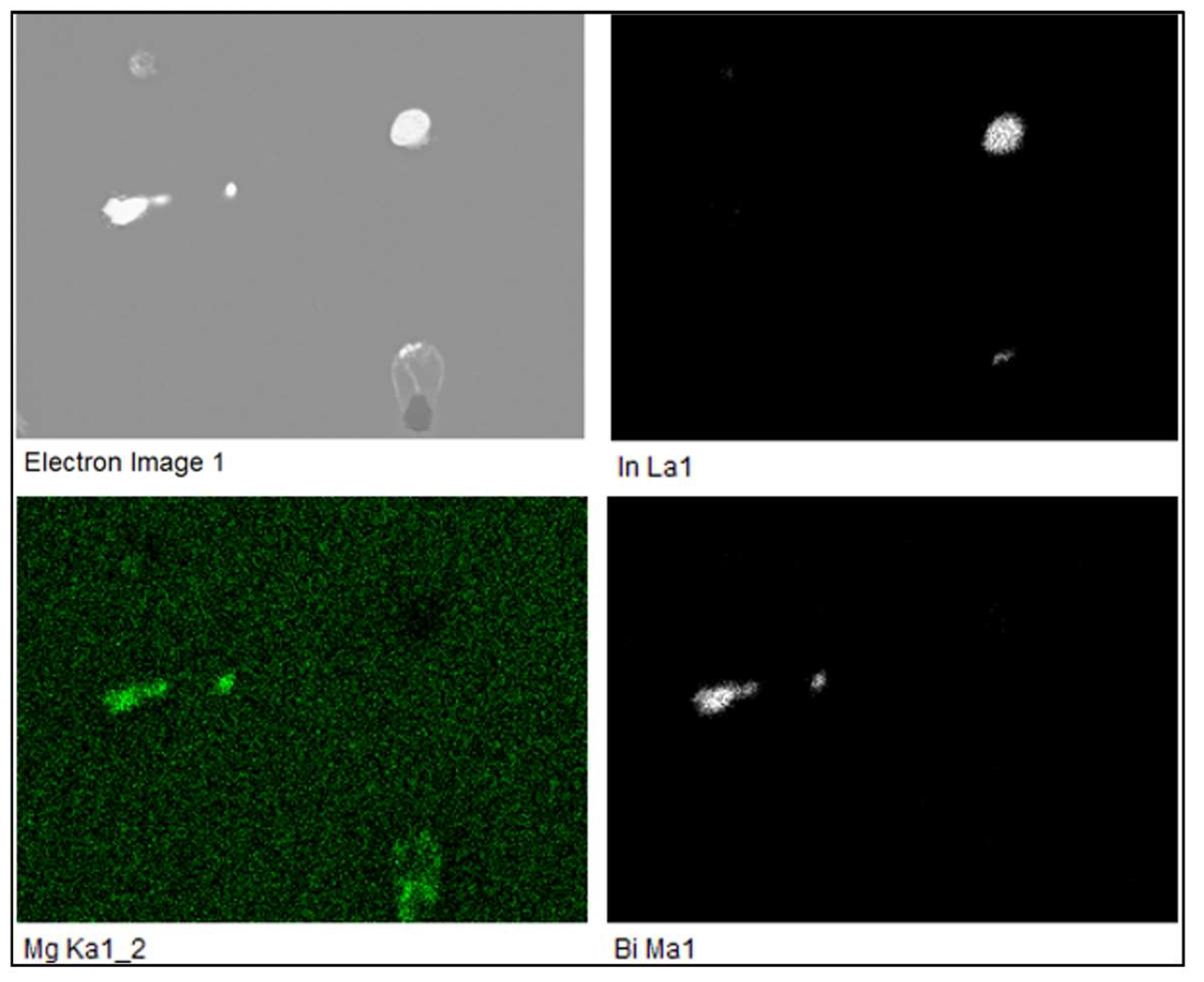
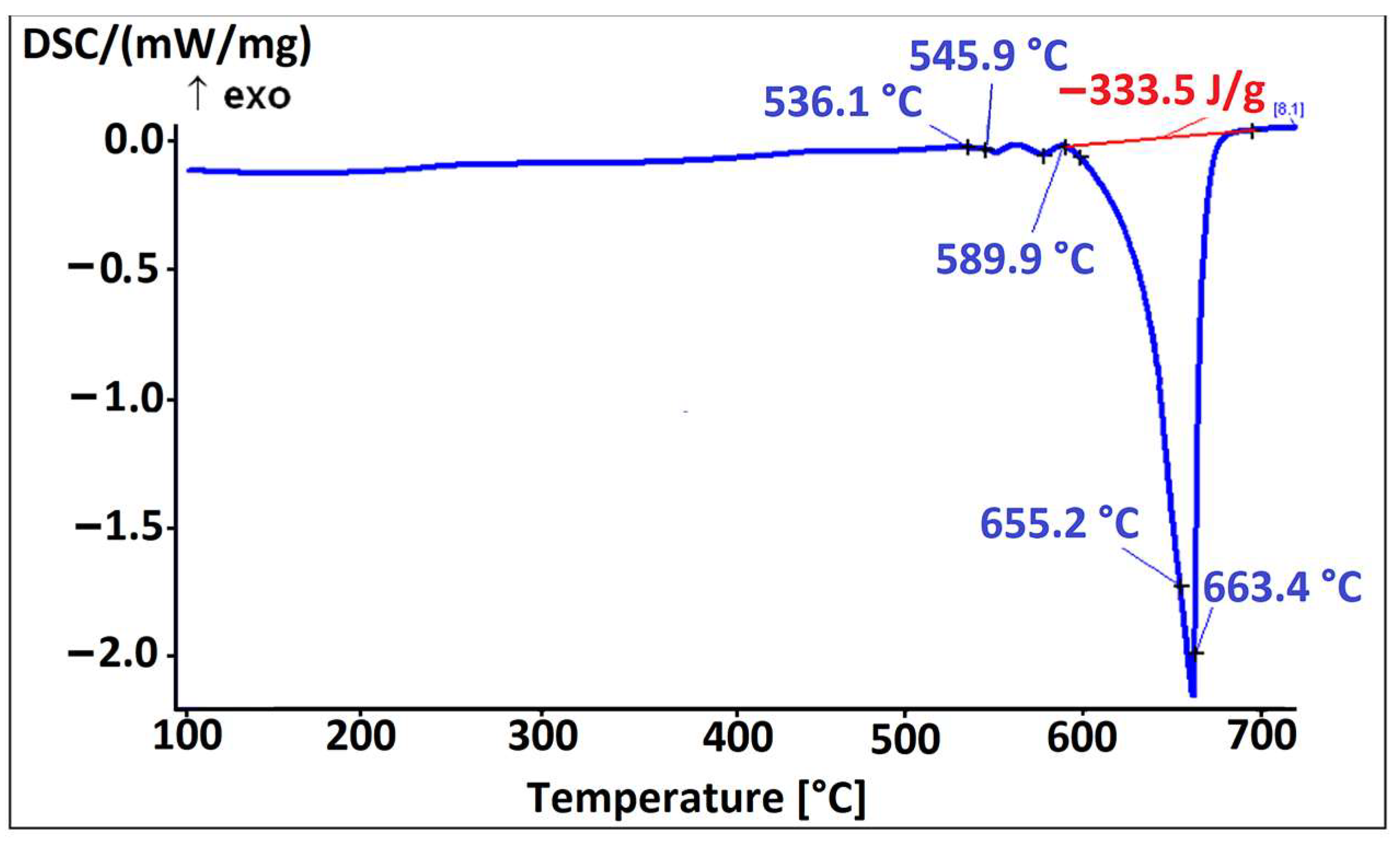
Figure 13 shows the microstructure of the alloy EN AW 6026-BiIn. Based on EDS analysis and a combination of equilibrium and non-equilibrium solidification diagrams, we identified the following microstructural phases: α-Al, Al15Si2(FeMn)4, Mg2Si, Al5Cu2Mg8Si6, Mg3Bi2, and indium particles. Morphologically, the Al5Cu2Mg8Si6 phases exhibited similar characteristics to those of the alloy EN AW 6026-In. EDS mapping was carried out to determine the specific distribution of each alloying element, focusing on Mg3Bi2 and In particles. Indium was found not to react with any of the alloying elements. However, in the case of Mg3Bi2 phase particles, an overlap between Bi and Mg was observed (Figure 14). Due to the formation of the Mg3Bi2 phase, the BiIn phase was not detected in the microstructure, unlike the alloy EN AW 1370-In. The DSC heating curve (Figure 15) did not show any endothermic peaks indicating the presence of the BiIn phase’s presence nor were there any prominent endothermic peaks in the temperature range from 150 °C to 170 °C, indicating the melting of indium. Nevertheless, Spectrum 3 in Figure 13 indicated that the identified proportion of indium was 96.28 wt.%, and the mapping analysis demonstrated that In did not interact with other elements, confirming its presence in its elemental form. The first significant endothermic peak (Figure 15) occurred within the temperature range of 536.1 °C to 545.9 °C, corresponding to the melting of the Al5Cu2Mg8Si6) and (α-Al + Mg2Si) eutectics. The most notable peaks corresponded to the melting of the (α-Al + α-Mg3Bi2) and (α-Al + Al15Si2(FeMn)4) eutectics at temperatures of 589.9 °C and 655.2 °C, and the α-Al solid solution melted at a temperature of 663.4 °C.
4. Conclusions
This article examines the microstructural and thermodynamic characterisation of laboratory-prepared aluminium alloys EN AW 1370 and EN AW 6026 with the addition of pure indium and an In–Bi master alloy, respectively. The aim of the experiments was the formation of a low-melting phase (TM < 350 °C), which was found in both alloys as indium particles.
- The microstructure of the alloy EN AW 1370-In consisted of α-Al, Al13Fe4, and pure indium particles, as confirmed via EDS analysis. Differential scanning calorimetry revealed endothermic peaks corresponding to the melting points of pure indium and two eutectics: ternary (α-Al + Al13Fe4 + (Al,In)) at 641.8 °C and binary (α-Al + Al13Fe4) at 653.8 °C, while the α-Al solid solution exhibited a melting point of 671.9 °C.
- The microstructure of the alloy EN AW 1370-BiIn consisted of α-Al, Al13Fe4, and a BiIn phase. Thermodynamic calculations suggest the possibility of a ternary eutectic (α-Al + Al8Fe2Si2+ (Al, In, Bi)). On the DSC heating curve, the melting of the BiIn phase was found to occur at 113.7 °C, which is very close to the BiIn phase melting point (109.7 °C) in the equilibrium Bi–In phase diagram. The melting points of the eutectics (α-Al + Al8Fe2Si2 + (Al, In, Bi)) and (α-Al + Al13Fe4) were detected at 646.4 °C and 658.5 °C, respectively, while the α-Al solid solution exhibited a melting point of 683.7 °C.
- The microstructure of the alloy EN AW 6026-In exhibited a higher degree of complexity and comprising an α-Al matrix, (α-Al + Al5Cu2Mg8Si6), (α-Al + Mg2Si), and (α-Al + Al15Si2(FeMn)4) binary eutectics as well as particles of elemental indium. Unfortunately, the DSC method could not reliably detect the melting or solidification of indium particles, due to their small number and the low enthalpy of indium. On the DSC heating curve, the initial prominent endothermic peak was seen at 532.4 °C, indicating melting of the (α-Al + Al5Cu2Mg8Si6) eutectic. Other endothermic peaks were observed at temperatures of 557.4 °C and 575.6 °C, indicating the melting of the (α-Al + Mg2Si) and (α-Al + Al15Si2(FeMn)4) eutectics, while the α-Al solid solution exhibited a melting point at 646.8 °C.
- The microstructure of the alloy EN AW 6026-BiIn consisted of the α-Al matrix; (α-Al + Al5Cu2Mg8Si6), (α-Al + Mg2Si), (α-Al + Mg3Bi2), and (α-Al + Al15Si2(FeMn)4) binary eutectics; and indium in elemental form. EDS mapping demonstrated that indium formed particles in elemental form and did not interact with other elements, while bismuth reacted with magnesium to form the Mg3Bi2 phase and prevent the formation of the BiIn phase. The DSC heating curve did not exhibit any endothermic peaks indicating the presence of the BiIn phase nor any prominent endothermic peaks corresponding to the melting of the indium particles. Instead, phase changes were observed at temperatures of 536.1 °C, 545.9 °C, 589.9 °C, and 655.2 °C and were attributed to the melting of the following eutectics (α-Al + Al5Cu2Mg8Si6), (α-Al + Mg2Si), (α-Al + α-Mg3Bi2), and (α-Al + Al15Si2(FeMn)4), while the α-Al solid solution melted at 663.4 °C.
Author Contributions
Conceptualization, J.M., S.R., A.N. and M.V.; methodology, S.R. and J.M.; validation, J.M., S.R., A.N. and M.V.; formal analysis, M.V. and A.N.; resources, J.M. and A.N.; data curation, S.R. and J.M.; writing—original draft preparation, S.R. and J.M.; writing—review and editing, J.M., A.N. and M.V.; supervision, J.M.; funding acquisition, J.M. and A.N. All authors have read and agreed to the published version of the manuscript.
Funding
This research was funded by Slovenian Research and Innovation Agency (ARIS) under the program Advanced Metallurgy, grant number P2-0344(B).
Institutional Review Board Statement
Not applicable.
Informed Consent Statement
Not applicable.
Data Availability Statement
Not applicable.
Conflicts of Interest
The authors declare no conflict of interest.
References
- Fujda, M.; Matvija, M.; Horňak, P. Effect of Pre-Straining and Natural Aging on the Hardening Response during Artificial Aging of EN AW 6082 and Lead Free EN AW 6023 Aluminium Alloys. Mater. Sci. Forum 2019, 952, 82–91. [Google Scholar] [CrossRef]
- Dubey, R.; Jayaganthan, R.; Ruan, D.; Gupta, N.K.; Jones, N.; Velmurugan, R. Energy absorption and dynamic behaviour of 6xxx series aluminium alloys: A review. Int. J. Impact Eng. 2023, 172, 104397. [Google Scholar] [CrossRef]
- Santos, M.C., Jr.; Machado, A.R.; Sales, W.F.; Barrozo, M.A.S.; Ezugwu, E.O. Machining of aluminum alloys: A review. Int. J. Adv. Manuf. Technol. 2016, 86, 3067–3080. [Google Scholar] [CrossRef]
- Varshney, D.; Kumar, K. Application and use of different aluminium alloys with respect to workability, strength and welding parameter optimization. Ain Shams Eng. J. 2021, 12, 1143–1152. [Google Scholar] [CrossRef]
- Karlík, M.; Faltus, J.; Nejezchlebová, J.; Haušild, P.; Harcuba, P. Characterisation of Al-Cu and Al-Mg-Si Free-Cutting Alloys. Mater. Sci. Forum 2014, 794–796, 1181–1186. [Google Scholar] [CrossRef]
- Timelli, G.; Bonollo, F. Influence of tin and bismuth on machinability of lead free 6000 series aluminium alloys. Mater. Sci. Technol. 2011, 27, 291–299. [Google Scholar] [CrossRef]
- Official Journal of the European Union. Directive 2002/95/EC of the European Parliament and of the Council of 27th January 2003 on the Restriction of the Use of Certain Hazardous Substances in Electrical and Electronic Equipment; Artesyn Technologies, Inc.: Boca Raton, FL, USA, 2005. [Google Scholar]
- Official Journal of the European Union. Directive 2000/53/EG of the European Parliament and of the Council of 18th September 2000 on End-of Life Vehicles (ELV). Off. J. Eur. Union 2020, 269, 34–43. [Google Scholar]
- Shalaby, R.M.; Abdelhakim, N.A.; Kamal, M. Effect of Rapid Solidification on Mechanical Properties of Free Machining Lead Free Aluminum Alloys for Improved Machinability. J. Adv. Phys. 2017, 13, 5155–5166. [Google Scholar]
- Smolej, A.; Breskvar, B.; Sokovic, M.; Dragojevic, V.; Slacek, E.; Smolar, T. Properties of aluminium free-cutting alloys with tin, Part I. Aluminium 2002, 78, 284–288. [Google Scholar]
- Barekar, N.S.; Skalicky, I.; Barbatti, C. Enhancement of chip breakability of aluminium alloys by controlling the solidification during direct chill casting. J. Alloys Compd. 2020, 862, 158008. [Google Scholar] [CrossRef]
- Santos, C.M.; Machado, A.R.; Barrozo, M.A.S. Temperature in Machining of Aluminum Alloys; Open access peer-reviewed chapter; IntechOpen: London, UK, 2018. [Google Scholar] [CrossRef]
- Dasch, J.M.; Ang, C.C.; Wong, C.A.; Waldo, R.A.; Chester, D.; Cheng, Y.T.; Powell, B.R.; Weiner, A.M.; Konca, E. The effect of free-machining elements on dry machining of B319 aluminum alloy. J. Mater. Process. Technol. 2009, 209, 4638–4644. [Google Scholar] [CrossRef]
- He, C.; Luo, B.; Zheng, Y.; Bai, Z.; Ren, Z. Effect of Sn on microstructure and corrosion behaviors of Al-Mg-Si alloys. Mater. Charact. 2019, 156, 109836. [Google Scholar] [CrossRef]
- Smolej, A.; Breskvar, B.; Sokovic, M.; Dragojevic, V.; Slacek, E.; Smolar, T. Properties of aluminium free-cutting alloys with tin, Part II. Aluminium 2002, 78, 388–391. [Google Scholar]
- Røyset, J.; Sæter, J.A.; Ustad, T.; Reiso, O. Effects of Sn Addition on Microstructure, Extrudability, Mechanical Properties and Machinability of a 6082 Alloy. Mater. Sci. Forum 2002, 396–402, 1205–1210. [Google Scholar] [CrossRef]
- Abdelhakim, N.A.; Shalaby, R.M.; Kamal, M. A Study of Structure, Thermal and Mechanical Properties of Free Machining Al-Zn-Sn-Bi Alloys Rapidly Solidified from Molten State. World J. Eng. Technol. 2018, 6, 637–650. [Google Scholar] [CrossRef]
- Faltus, J.; Karlík, M.; Haušild, P. Influence of the chemical composition on the structure and properties of lead-free machinable AA 6023 (Al-Mg-Si-Sn-Bi) alloy. In Proceedings of the 13th International Conference on Aluminum Alloys (ICAA13): TMS (The Minerals, Metals & Materials Society), Pittsburgh, PA, USA, 3–7 June 2012; pp. 1545–1550. [Google Scholar]
- Rečnik, S.; Medved, J.; Kevorkijan, V.M.; Žist, S. An Advanced Industrial Methodology for Optimizing the Properties and the Process of Homogenization for Extruded AA2xxx and AA6xxx. In Light Metals; Eskin, D., Ed.; The Minerals, Metals & Materials Series; Springer: Cham, Switzerland, 2022. [Google Scholar] [CrossRef]
- Rečnik, S.; Bizjak, M.; Medved, J.; Cvahte, P.; Karpe, B.; Nagode, A. Mechanism of the Mg3Bi2 Phase Formation in Pb-Free Aluminum 6xxx Alloy with Bismuth Addition. Crystals 2021, 11, 424. [Google Scholar] [CrossRef]
- Sircar, S. Free-Machining Aluminum Alloy and Method of Use. U.S. Patent 6315947, 13 November 2001. [Google Scholar]
- Sircar, S. Machineable Aluminum Alloys Containing In and Sn and Process for Producing the Same. U.S. Patent 5587029, 24 December 1996. [Google Scholar]
- Binary Phase Diagrams Database; ASM International: Novelty, OH, USA, 1996.
- Sundman, B.; Kattner, R.U.; Palumbo, M.; Fries, G.S. OpenCalphad—A free thermodynamic software. Integr. Mater. Manuf. Innov. 2015, 4, 1–15. [Google Scholar] [CrossRef]
Figure 1.
Isopleth phase diagram for EN AW 6026-In.

Figure 2.
(a) Diagram of the proportion of phases as a function of temperature for sample EN AW 6026-In; (b) Scheil’s diagram for sample EN AW 6026-In.
Figure 2.
(a) Diagram of the proportion of phases as a function of temperature for sample EN AW 6026-In; (b) Scheil’s diagram for sample EN AW 6026-In.

Figure 3.
SEM micrograph of EN AW 1370-In with EDS results [wt.%].

Figure 4.
DSC heating curve of the EN AW 1370-In alloy.

Figure 5.
SEM micrograph of ternary eutectic (α-Al + Al13Fe4 + (Al,In)) with EDS results [wt.%].

Figure 6.
SEM micrograph of EN AW 1370-BiIn alloy.

Figure 7.
SEM micrograph of EN AW 1370-BiIn with EDS results [wt.%].

Figure 8.
Spherical eutectic particle in the microstructure of the EN AW 1370-BiIn alloy with EDS results [wt.%].
Figure 8.
Spherical eutectic particle in the microstructure of the EN AW 1370-BiIn alloy with EDS results [wt.%].

Figure 9.
DSC heating curve of sample EN AW 1370-BiIn.

Figure 10.
SEM micrograph of the alloy EN AW 6026-In with EDS results [wt.%].

Figure 11.
DSC heating curve of the EN AW 6026-In alloy.

Figure 12.
Spherical eutectic in EN AW 6026-In alloy with EDS results [wt.%].

Figure 13.
SEM micrograph of the alloy EN AW 6026-BiIn with EDS results [wt.%].

Figure 14.
EDS elemental mapping of In, Mg, and Bi in the alloy EN AW 6026-BiIn.

Figure 15.
DSC heating curve of the EN AW 6026-BiIn alloy.


Table 1.
Chemical composition of the EN AW 6026 alloy.
| Element | Si | Fe | Cu | Mn | Mg | Cr | Zn | Ti | Al |
|---|---|---|---|---|---|---|---|---|---|
| wt.% | 1.134 | 0.201 | 0.332 | 0.747 | 0.825 | 0.016 | 0.028 | 0.017 | Bal. |
Table 2.
Chemical composition of the EN AW 1370 alloy.
| Element | Si | Fe | Cu | Mn | Zn | Ti | Al |
|---|---|---|---|---|---|---|---|
| wt.% | 0.051 | 0.144 | 0.047 | 0.007 | 0.014 | 0.006 | Bal. |
Table 3.
Designation of samples and content of added alloying elements.
| Designation | Basic Alloy | Content of Added Element in [wt.%] |
|---|---|---|
| EN AW 1370-In | EN AW 1370 | 1 wt.% In |
| EN AW 1370-BiIn | EN AW 1370 | 1 wt.% BiIn |
| EN AW 6026-In | EN AW 6026 | 1 wt.% In |
| EN AW 6026-BiIn | EN AW 6026 | 1 wt.% BiIn |
Table 4.
Chemical composition of synthesized alloys.
| Designation | Si | Fe | Cu | Mn | Mg | Cr | Zn | Ti | Bi | In | Al |
|---|---|---|---|---|---|---|---|---|---|---|---|
| EN AW 1370-In | 0.056 | 0.167 | / | 0.007 | 0.002 | 0.001 | 0.009 | 0.002 | / | 1.041 | Bal. |
| EN AW 1370-BiIn | 0.051 | 0.142 | / | 0.006 | 0.001 | 0.001 | 0.007 | 0.001 | 0.664 | 0.373 | Bal. |
| EN AW 6026-In | 1.145 | 0.201 | 0.319 | 0.751 | 0.822 | 0.015 | 0.024 | 0.016 | / | 1.082 | Bal. |
| EN AW 6026-BiIn | 1.113 | 0.244 | 0.324 | 0.774 | 0.832 | 0.016 | 0.021 | 0.014 | 0.684 | 0.321 | Bal. |
Table 5.
Calculated phases in equilibrium state and Scheil’s calculation with the Thermo-Calc software for all four alloys.
Table 5.
Calculated phases in equilibrium state and Scheil’s calculation with the Thermo-Calc software for all four alloys.
| LIQUID = liquid | MG2SI = Mg2Si |
| LIQUID #1 = liquid based on (Al, In, Fe, Si, Mg, ...) | DIAMOND_A4 = β-Si |
| LIQUID #2 = liquid based on (In, Al, …) | AL13CR4SI4 = Al13Cr4Si4 |
| FCC_L12 = α-Al | AL9FE2SI2 = Al9Fe2Si2 |
| FCC_L12#2 = α-Al (Bi) | Q_AlCUMGSI = Al5Cu2Mg8Si6 |
| AL15SI2M4 = Al15Si2(FeMn)4 | RHOMBO_A7 = Bi |
| AL13FE4 = Al13Fe4 | TETRA_A6 = In |
| AL8FE2SI = Al8Fe2Si | HCP_A3 = (In,Zn) |
| AL8FE2SI2 = Al8Fe2Si2 | BCT_A5 = (Al,In) |
Disclaimer/Publisher’s Note: The statements, opinions and data contained in all publications are solely those of the individual author(s) and contributor(s) and not of MDPI and/or the editor(s). MDPI and/or the editor(s) disclaim responsibility for any injury to people or property resulting from any ideas, methods, instructions or products referred to in the content. |
© 2023 by the authors. Licensee MDPI, Basel, Switzerland. This article is an open access article distributed under the terms and conditions of the Creative Commons Attribution (CC BY) license (https://creativecommons.org/licenses/by/4.0/).
Share and Cite
MDPI and ACS Style
Rečnik, S.; Vončina, M.; Nagode, A.; Medved, J. Thermodynamic and Microstructural Analysis of Lead-Free Machining Aluminium Alloys with Indium and Bismuth Additions. Materials 2023, 16, 6241. https://doi.org/10.3390/ma16186241
AMA Style
Rečnik S, Vončina M, Nagode A, Medved J. Thermodynamic and Microstructural Analysis of Lead-Free Machining Aluminium Alloys with Indium and Bismuth Additions. Materials. 2023; 16(18):6241. https://doi.org/10.3390/ma16186241
Chicago/Turabian StyleRečnik, Simon, Maja Vončina, Aleš Nagode, and Jožef Medved. 2023. "Thermodynamic and Microstructural Analysis of Lead-Free Machining Aluminium Alloys with Indium and Bismuth Additions" Materials 16, no. 18: 6241. https://doi.org/10.3390/ma16186241
Note that from the first issue of 2016, this journal uses article numbers instead of page numbers. See further details here.