
Experimental Investigation on the Influence of Crack Width of Asphalt Concrete on the Repair Effect of Microbially Induced Calcite Precipitation

Abstract
:1. Introduction
2. Material and Sample Preparation
2.1. Sample Preparation
2.2. Bacterial Culture and Cementing Solution
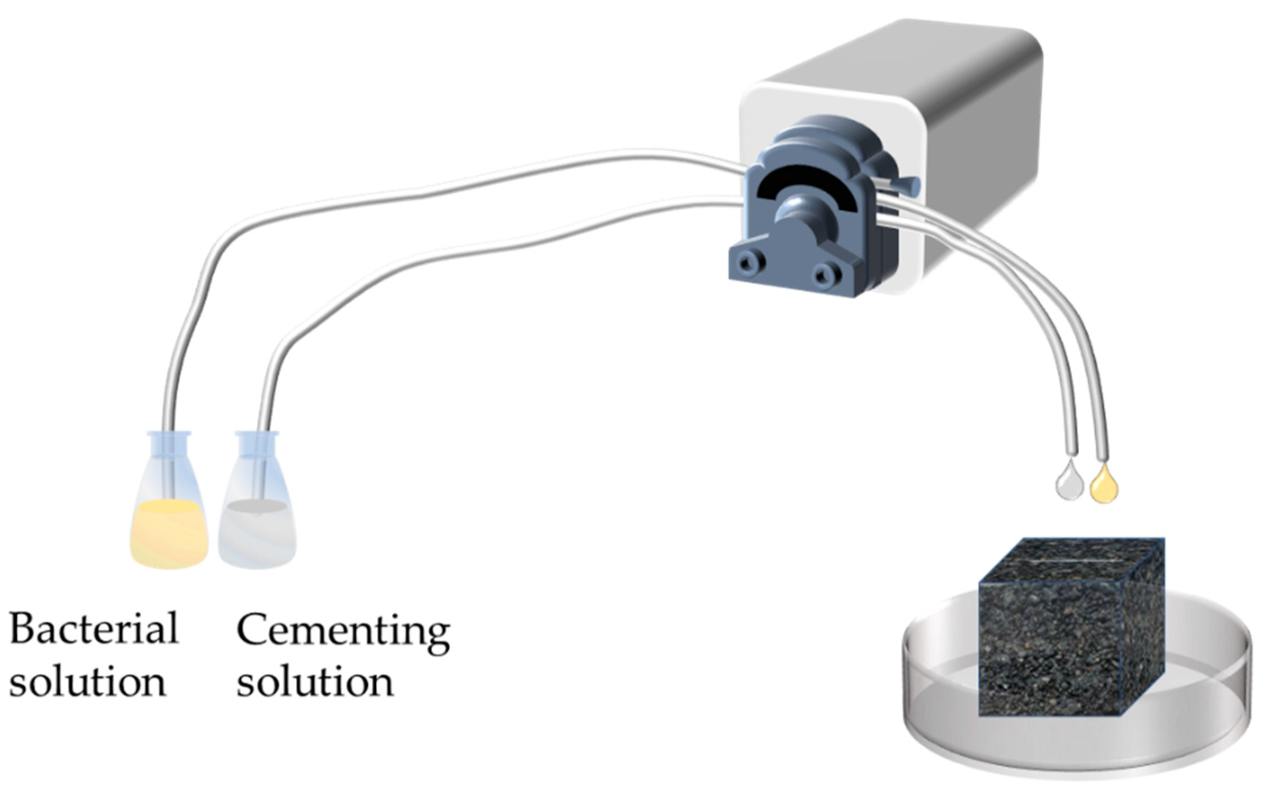
2.3. Crack Repair Methods
3. Evaluation of Repair Effect
3.1. Compressive Strength
3.2. Indirect Tensile Strength
3.3. Static Creep Test
3.4. SEM/EDS
4. Analysis and Evaluation of the Effect of Repairing the Width of Small Cracks (≤1.5 mm)
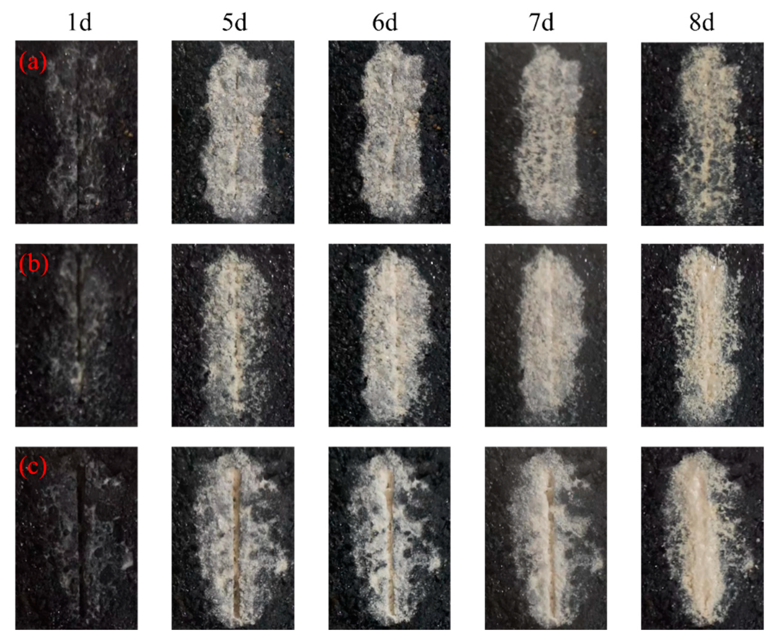
4.1. Observation of Repair Effect
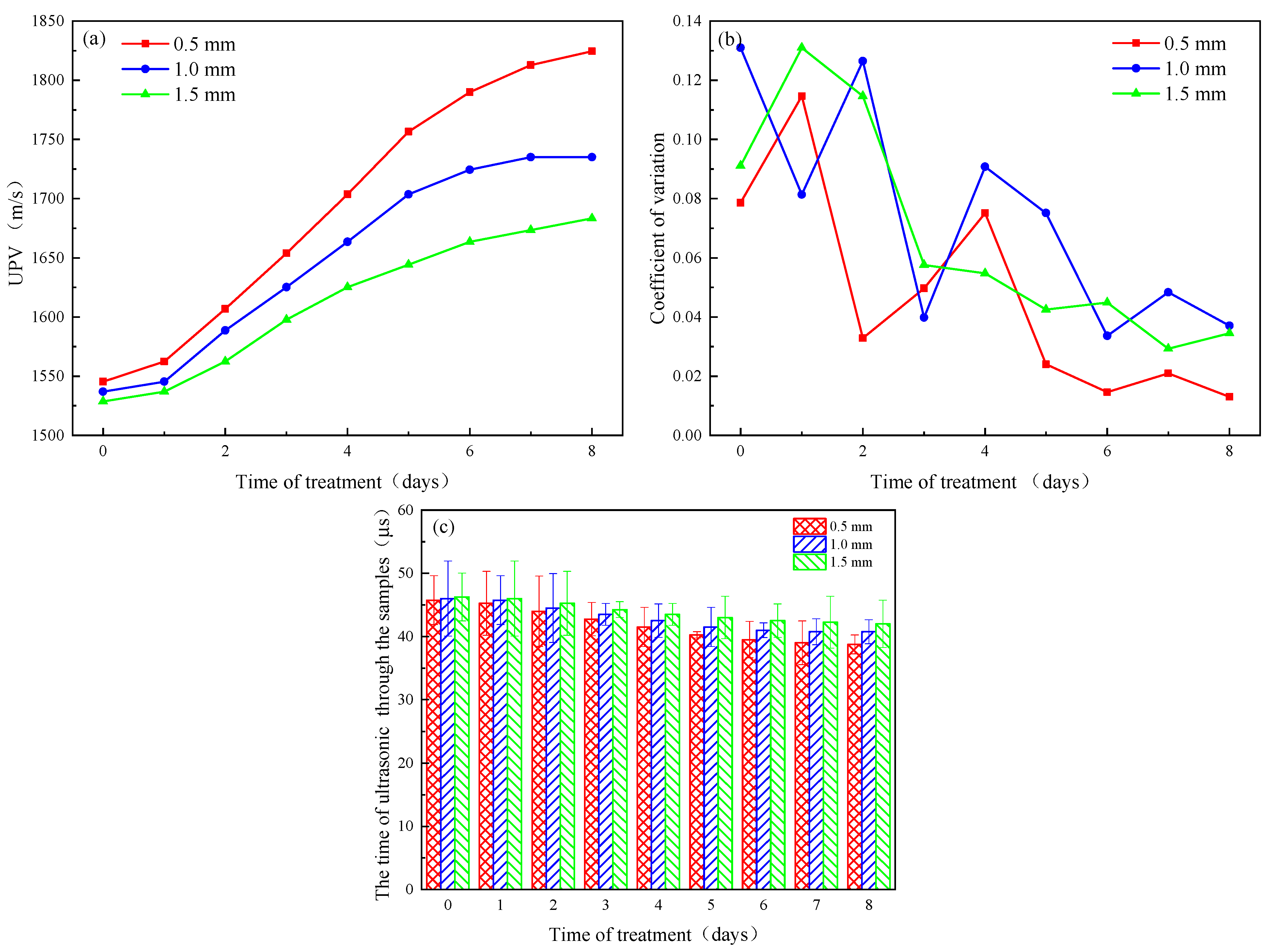
4.2. UPV
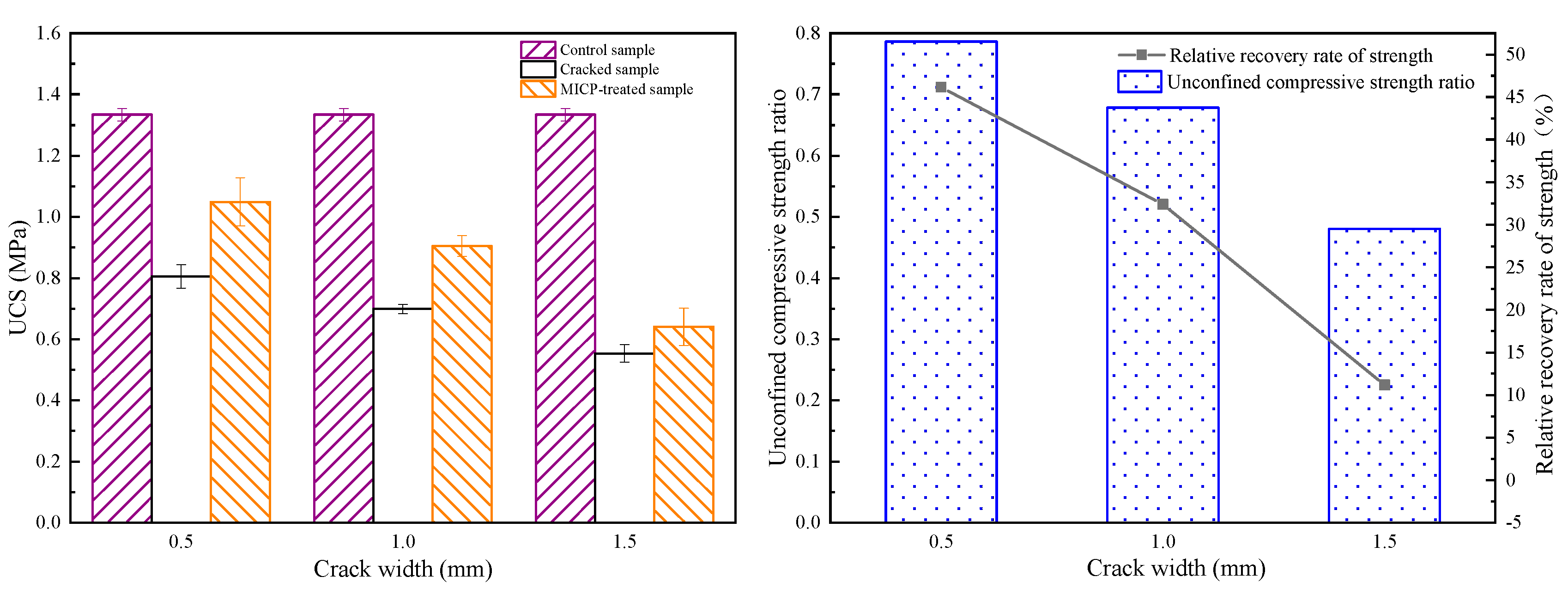
4.3. UCS
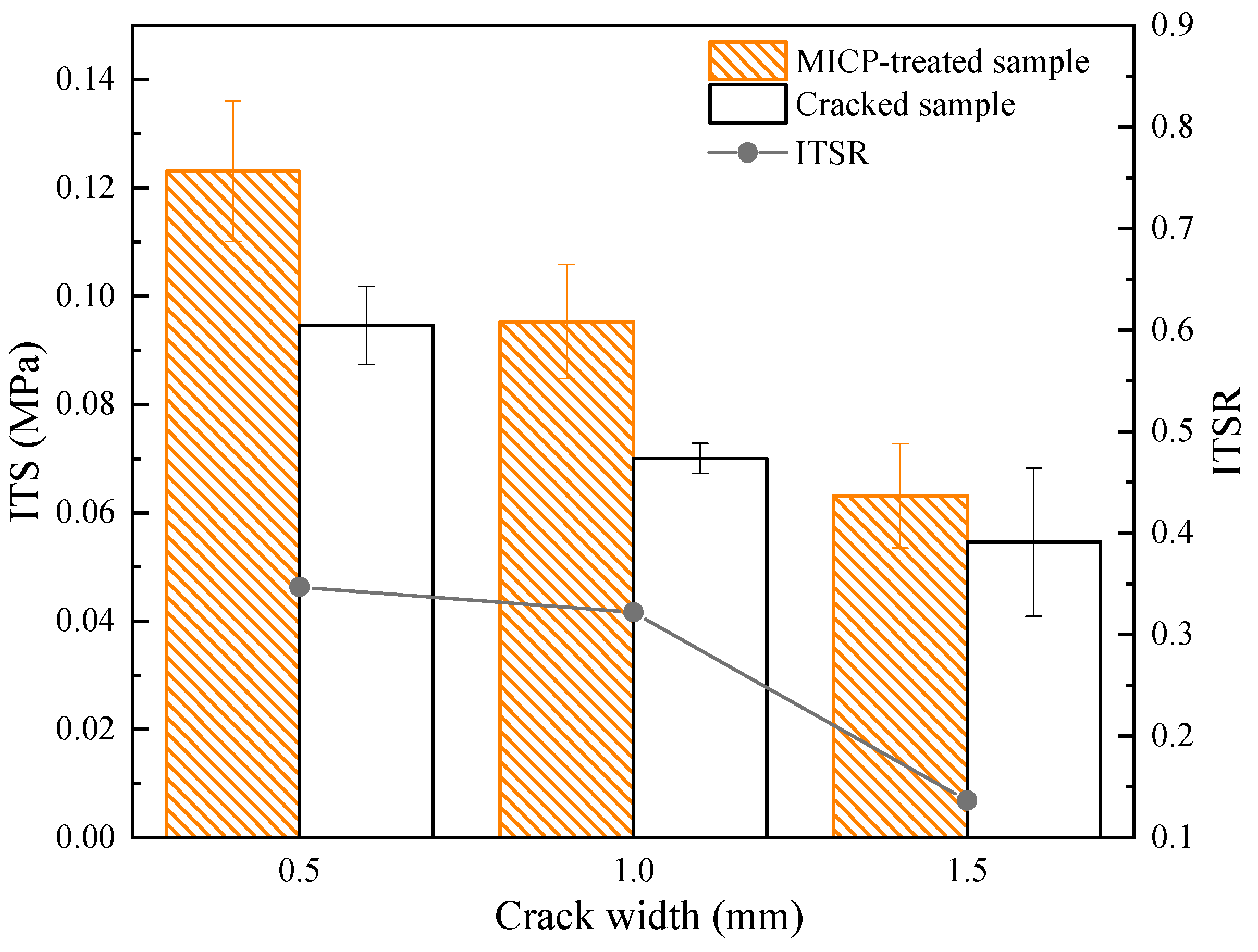
4.4. ITS
4.5. Permanent Deformation
4.6. SEM/EDS Analysis
5. Analysis and Evaluation of the Effect of Repairing Large-Width Cracks (3 mm)
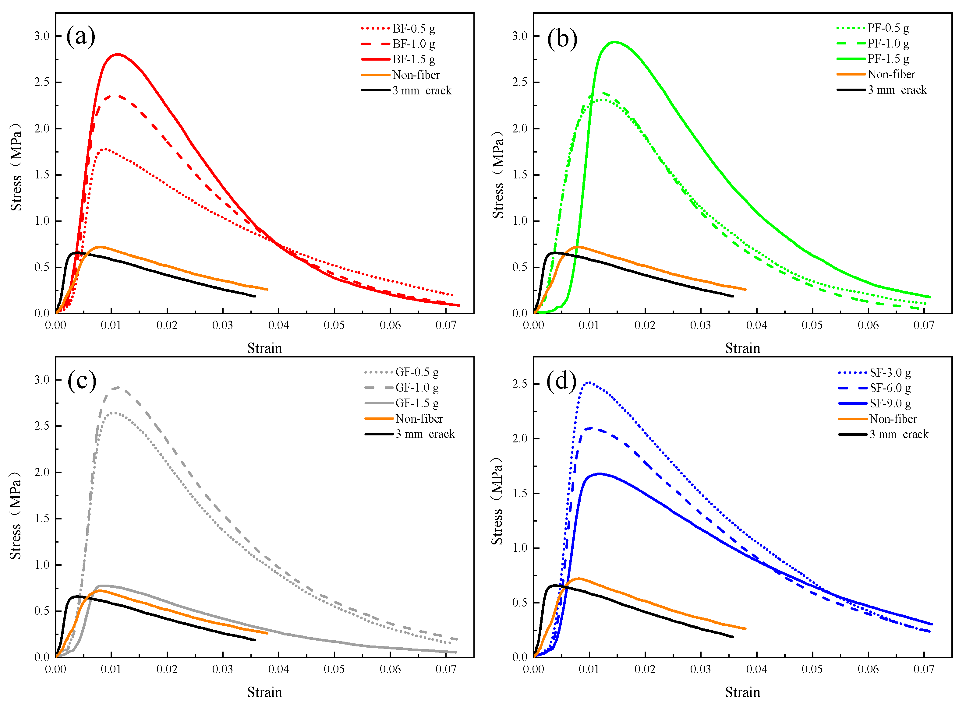
5.1. Effect of MICP Repair for Different Types of Fibers
- (1)
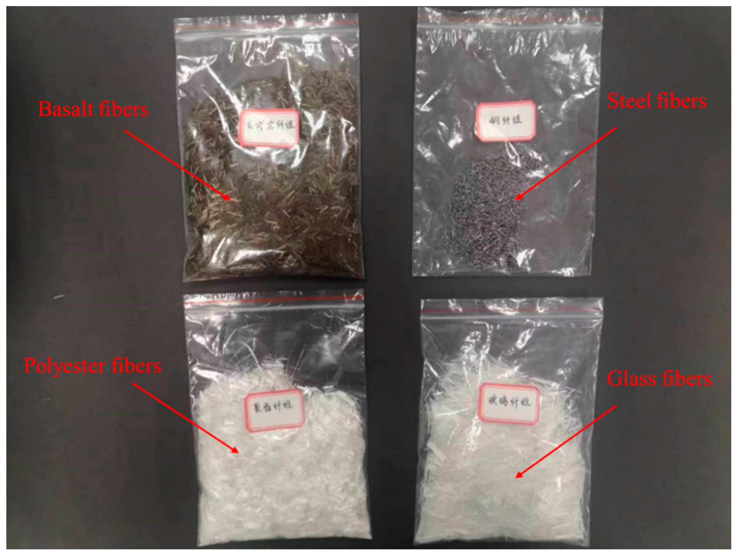
- In the MICP repair process, the different fibers added in the cracks, even though they have the same quality, show different repair effects due to their different softness and volume, resulting in different distribution patterns in the cracks and different interaction relationships with the asphalt binder, aggregates, and MICP products.
- (2)
- In the case of basalt fiber, its texture is hard, and it plays the role of strengthening the interconnection between calcium carbonate particles, and also provides the landing point for bacteria; in the case of polyester fiber, its texture is soft and it is more aggregated and distributed under the infiltration of slurry, which plays the local geotextile effect; for glass fiber, its softness and hardness are between basalt fiber and polyester fiber, and due to its longer length, it becomes entangled in the cracks. This winding effect can also strengthen the cementation between calcium carbonate particles, aggregates, and fibers to a certain extent; in the case of steel fibers, it has the hardest texture and the largest mass in the same volume, and the interlocking between fibers can also lead to the local siltation of calcium carbonate when repairing cracks via MICP due to the sinking through gravity, resulting in the effect with steel fibers where the MICP repair only occurs in a certain depth range of the cracks.
5.2. Investigation of Optimal Fiber Doping
6. Discussion
7. Conclusions
- (1)
- The wave speed increased from 1545.36, 1536.96, and 1528.65 m/s to 1824.52, 1734.97, and 1683.33 m/s for crack widths of 0.5 mm, 1.0 mm, and 1.5 mm, respectively, and the uniaxial compressive strength for the MICP-repaired samples also increased compared to the unrepaired samples by 78.94%, 67.67%, and 48.12%, respectively. In addition, the recovery rates of indirect tensile strength were 34.68%, 32.19%, and 13.64%, respectively.
- (2)
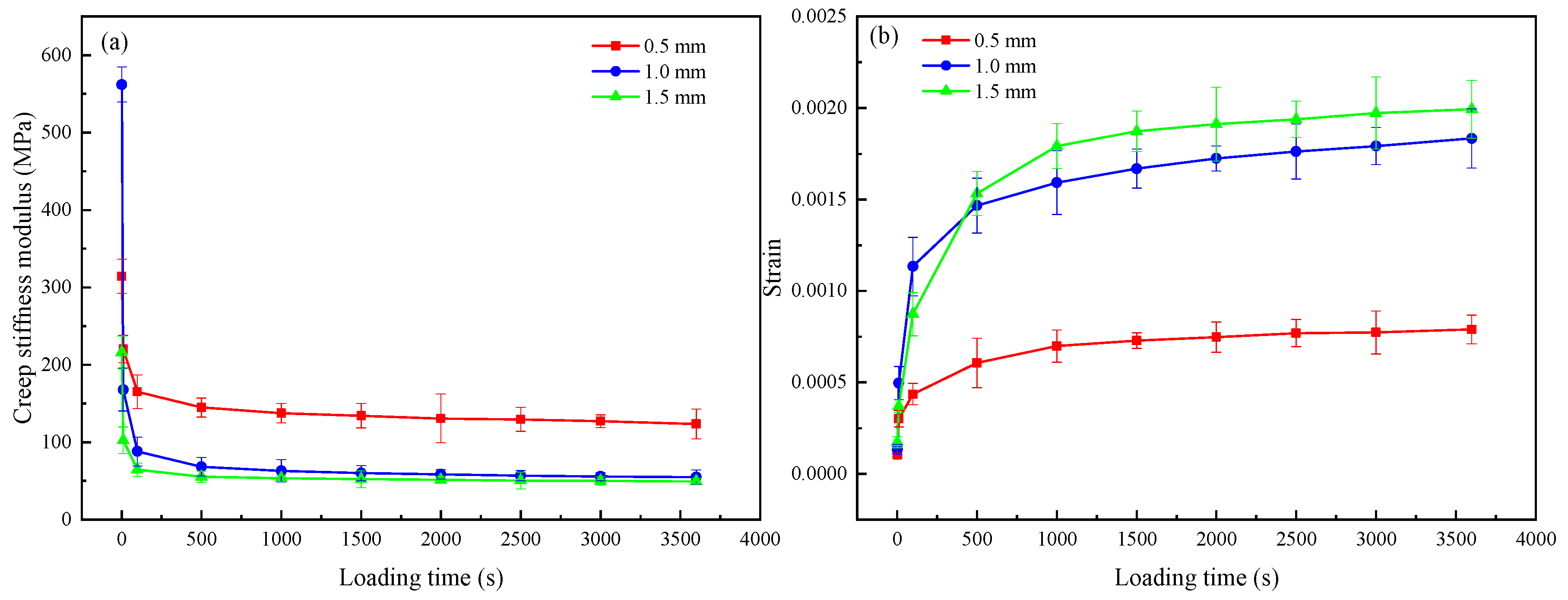
- The static creep test results showed that the creep modulus of the MICP samples was finally stabilized at 123.85 MPa, 54.83 MPa, and 49.83 MPa after 3600 s of constant pressure loading, indicating that the repaired MICP with a crack width of 0.5 mm had greater resistance to deformation.
- (3)
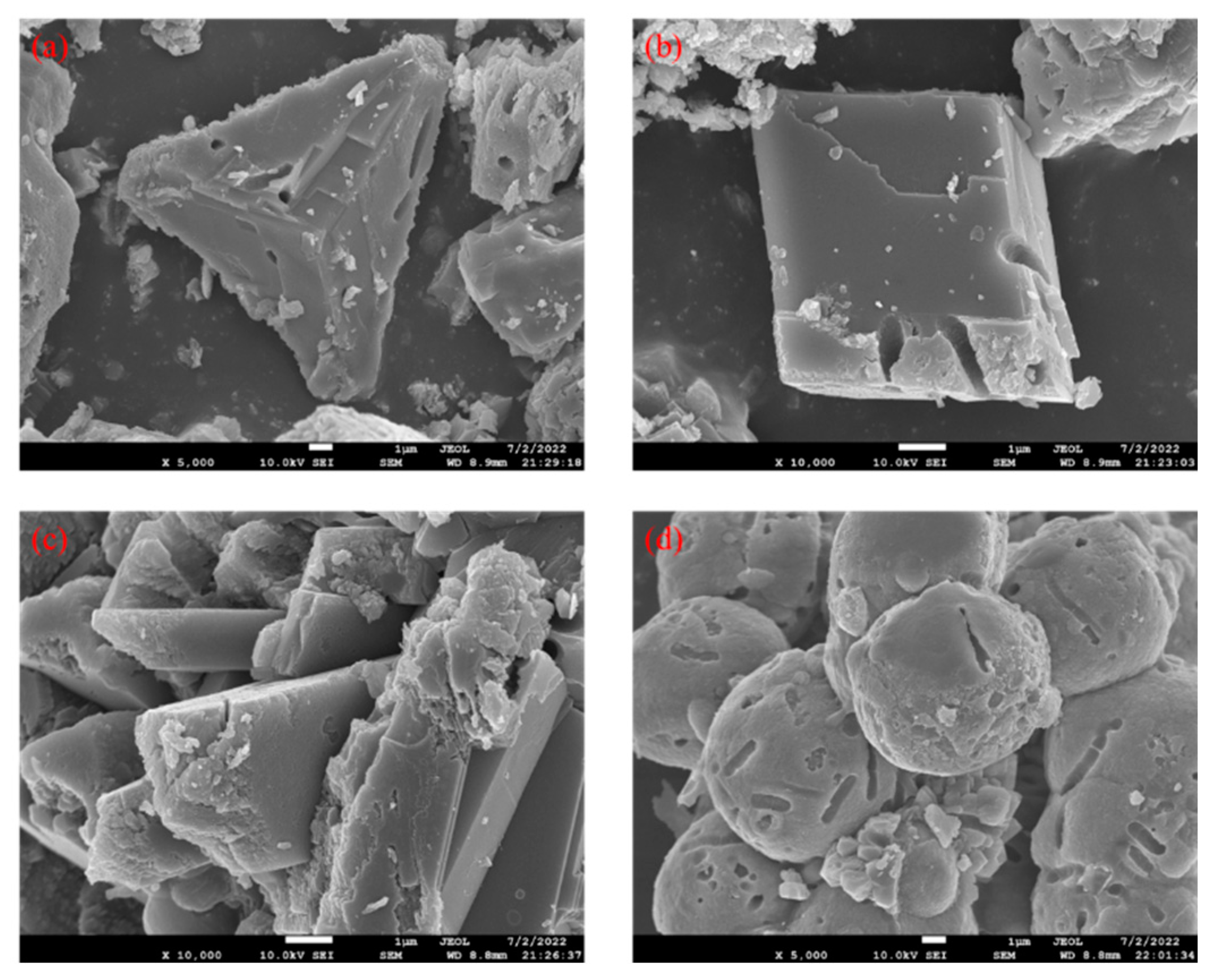
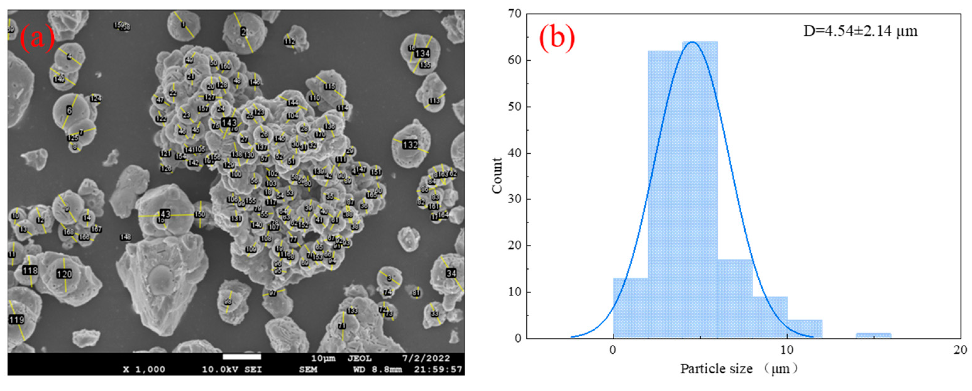
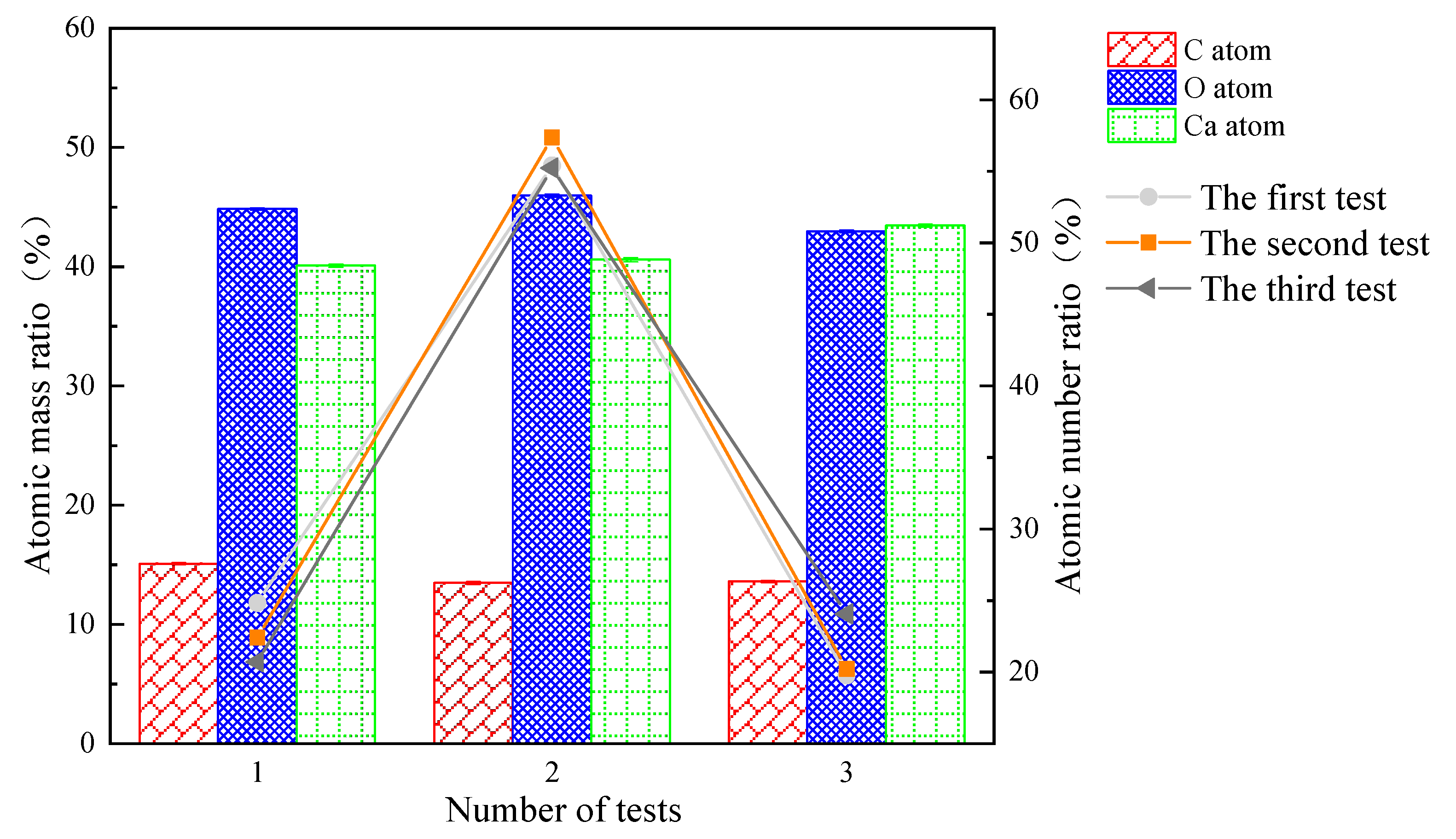
- SEM and EDS images showed that the MICP product of this study was CaCO3, which was mainly in the form of spherical calcite. the particle size of CaCO3 was mostly concentrated within 10 μm, with an average value of 4.54 μm.
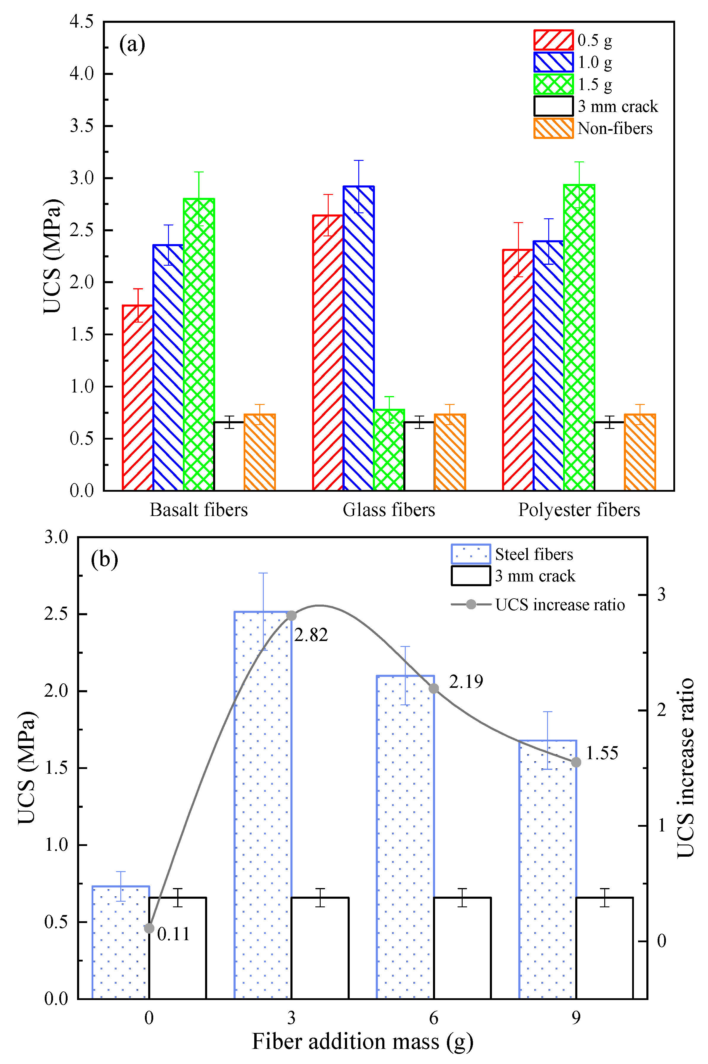
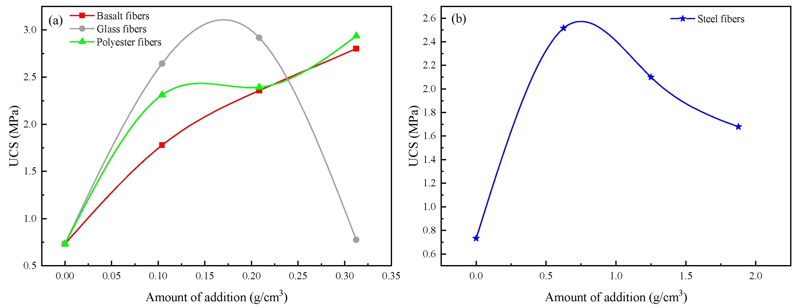
- (4)
- The results of MICP combined with different fibers to repair large-width cracks showed that the addition of fibers contributed to the filling effect of the MICP product in the cracks of the as-built concrete. the UCS results showed that the optimum dose was about 0.18 g/cm3 for glass fibers, about 0.83 g/cm3 for steel fibers, and over 0.31 g/cm3 for polyester and basalt fibers.
Author Contributions
Funding
Institutional Review Board Statement
Informed Consent Statement
Data Availability Statement
Conflicts of Interest
Abbreviations
| Abbreviation | Definition |
| MICP | microbially induced calcium precipitation |
| SEM | scanning electron microscope |
| EDS | energy dispersive spectrometer |
| CAEM | cold asphalt emulsion mixes |
| UPV | ultrasonic pulse velocity |
| UCS | uniaxial compressive strength |
| ITS | indirect tensile strength |
| BF | basalt fiber |
| PF | polyester fiber |
| GF | glass fiber |
| SF | steel fiber |
References
- Yang, Z. Study on Multi-Scale Behavioral Characteristics of Asphaltbefore and after Aging. Ph.D. Thesis, South China University of Technology, Guangzhou, China, 2018. [Google Scholar]
- Kim, H.; Wagoner, M.P.; Buttlar, W.G. Simulation of Fracture Behavior in Asphalt Concrete Using a Heterogeneous Cohesive Zone Discrete Element Model. J. Mater. Civ. Eng. 2008, 20, 552–563. [Google Scholar] [CrossRef]
- Ma, Z.; Liu, L.; Sun, L. Investigation of top-down cracking performance of in-situ asphalt mixtures based on accelerated pavement testing and laboratory tests. Constr. Build. Mater. 2018, 179, 177–184. [Google Scholar] [CrossRef]
- Cascione, A.A.; Williams, R.C.; Yu, J. Performance testing of asphalt pavements with recycled asphalt shingles from multiple field trials. Constr. Build. Mater. 2015, 101, 628–642. [Google Scholar] [CrossRef]
- Zhang, Z.; Sun, J.; Huang, Z.; Wang, F.; Jia, M.; Lv, W.; Ye, J. A laboratory study of epoxy/polyurethane modified asphalt binders and mixtures suitable for flexible bridge deck pavement. Constr. Build. Mater. 2021, 274, 122084. [Google Scholar] [CrossRef]
- Shafabakhsh, G.; Ahmadi, S. Reflective cracking reduction by a comparison between modifying asphalt overlay and sand asphalt interlayer: An experimental evaluation. Int. J. Pavement Eng. 2019, 22, 192–200. [Google Scholar] [CrossRef]
- Moreno-Navarro, F.; Sol-Sánchez, M.; Rubio-Gámez, M.C. The effect of polymer modified binders on the long-term performance of bituminous mixtures: The influence of temperature. Mater. Design 2015, 78, 5–11. [Google Scholar] [CrossRef]
- Fan, T.; Si, C.; Zhang, Y.; Zhu, Y.; Li, S. Optimization Design of Asphalt Mixture Composite Reinforced with Calcium Sulfate Anhydrous Whisker and Polyester Fiber Based on Response Surface Methodology. Materials 2023, 16, 594. [Google Scholar] [CrossRef]
- Xue, X.; Gao, J.; Wang, J.; Chen, Y. Evaluation of High-Temperature and Low-Temperature Performances of Lignin-Waste Engine Oil Modified Asphalt Binder and Its Mixture. Materials 2021, 15, 52. [Google Scholar] [CrossRef]
- Li, H.; Yu, J.; Wu, S.; Liu, Q.; Li, Y.; Wu, Y.; Xu, H. Investigation of the Effect of Induction Heating on Asphalt Binder Aging in Steel Fibers Modified Asphalt Concrete. Materials 2019, 12, 1067. [Google Scholar] [CrossRef]
- Khater, A.; Luo, D.; Abdelsalam, M.; Ma, J.; Ghazy, M. Comparative Life Cycle Assessment of Asphalt Mixtures Using Composite Admixtures of Lignin and Glass Fibers. Materials 2021, 14, 6589. [Google Scholar] [CrossRef]
- Wang, W.; Cheng, Y.; Tan, G. Design Optimization of SBS-Modified Asphalt Mixture Reinforced with Eco-Friendly Basalt Fiber Based on Response Surface Methodology. Materials 2018, 11, 1311. [Google Scholar] [CrossRef] [PubMed]
- Awuah, F.K.A.; Garcia-Hernández, A. Machine-filling of cracks in asphalt concrete. Automat. Constr. 2022, 141, 104463. [Google Scholar] [CrossRef]
- Yin, J.; Pang, Q.; Wu, H.; Song, W. Using a polymer-based sealant material to make crack repair of asphalt pavement. J. Test. Eval. 2018, 46, 20170041. [Google Scholar] [CrossRef]
- Gnatenko, R.; Tsyrkunova, K.; Zhdanyuk, V. Technological Sides of Crack Sealing in Asphalt Pavements. Transport. Res. Procedia 2016, 14, 804–810. [Google Scholar] [CrossRef]
- Wang, Y.; Kong, L.; Chen, Q.; Lau, B.; Wang, Y. Research and application of a black rapid repair concrete for municipal pavement rehabilitation around manholes. Constr. Build. Mater. 2017, 150, 204–213. [Google Scholar] [CrossRef]
- Sun, X.; Miao, L.; Wu, L.; Wang, H. Theoretical quantification for cracks repair based on microbially induced carbonate precipitation (MICP) method. Cem. Concr. Comp. 2021, 118, 103950. [Google Scholar] [CrossRef]
- Cheng, L.; Kobayashi, T.; Shahin, M.A. Microbially induced calcite precipitation for production of “bio-bricks” treated at partial saturation condition. Constr. Build. Mater. 2020, 231, 117095. [Google Scholar] [CrossRef]
- Peng, S.; Zhang, K.; Fan, L.; Kang, J.; Peng, K.; Wang, F.; Chen, Z. Permeability Reduction and Electrochemical Impedance of Fractured Rock Grouted by Microbial-Induced Calcite Precipitation. Geofluids 2020, 2020, 8876400. [Google Scholar] [CrossRef]
- Iqbal, D.M.; Wong, L.S.; Kong, S.Y. Bio-Cementation in Construction Materials: A Review. Materials 2021, 14, 2175. [Google Scholar] [CrossRef]
- Attaran Dovom, H.; Mohammadzadeh Moghaddam, A.; Karrabi, M.; Shahnavaz, B.; Attaran Dowom, S. Investigation of the mechanical and physical properties of bio-modified cold asphalt emulsion mixtures by microbial carbonate precipitation. Int. J. Pavement Eng. 2019, 22, 404–417. [Google Scholar] [CrossRef]
- Attaran Dovom, H.; Mohammadzadeh Moghaddam, A.; Karrabi, M.; Shahnavaz, B. Improving the resistance to moisture damage of cold mix asphalt modified by eco-friendly Microbial Carbonate Precipitation (MCP). Constr. Build. Mater. 2019, 213, 131–141. [Google Scholar] [CrossRef]
- Xin, J.; Pei, J.; Akiyama, M.; Li, R.; Zhang, J.; Shao, L. A Study on the Design Method for the Material Composition of Small Particle-Size Asphalt Mixture for Controlling Cracks in Asphalt Pavement. Appl. Sci. 2019, 9, 1988. [Google Scholar] [CrossRef]
- Uhlmeyer, J.S.; Willoughby, K.; Pierce, L.M. Top-Down Cracking in Washington State Asphalt Concrete Wearing Courses. Transport. Res. Rec. 2000, 1730, 110–116. [Google Scholar] [CrossRef]
- Brown, E.R. Designing stone matrix asphalt mixtures for rut-resistant pavements (no. 425–430). In Transportation Research Board; Transportation Research Board, National Research Council: Washington, DC, USA, 1999. [Google Scholar]
- Bani Baker, M.I.; Abendeh, R.M.; Khasawneh, M.A. Freeze and Thaw Effect on Asphalt Concrete Mixtures Modified with Natural Bentonite Clay. Coatings 2022, 12, 1664. [Google Scholar] [CrossRef]
- Ministry of Transport of the People’ Republic of China. Standard Test Methods of Bitumen and Bituminous Mixtures for Highway Engineering JTG E20–2011; China Communication Press: Beijing, China, 2011. [Google Scholar]
- Quintus, H.V.; Hughes, C.S.; Scherocman, J.A. NCHRP asphalt-aggregate mixture analysis system. Transport. Res. Rec. 1992, 1353, 90–99. [Google Scholar]
- Jongvivatsakul, P.; Janprasit, K.; Nuaklong, P. Investigation of the crack healing performance in mortar using microbially induced calcium carbonate precipitation (MICP) method. Constr. Build. Mater. 2019, 212, 737–744. [Google Scholar] [CrossRef]
- Wang, Z.; Ning, J.; Ren, H. Frequency characteristics of the released stress wave by propagating cracks in brittle materials. Theor. Appl. Fract. Mech. 2018, 96, 72–82. [Google Scholar] [CrossRef]
- Qian, C.; Zheng, T.; Zhang, X.; Su, Y. Application of microbial self-healing concrete: Case study. Constr. Build. Mater. 2021, 290, 123226. [Google Scholar] [CrossRef]
- Pannem, R.; Chintalapudi, K. Evaluation of Strength Properties and Crack Mitigation of Self-healing Concrete. Jordan J. Civ. Eng. 2019, 13, 386–393. [Google Scholar]
- Sun, X.H.; Miao, L.C. Application of Bio-remediation with Bacillus megaterium for Crack Repair at Low Temperature. J. Adv. Concr. Technol. 2020, 18, 307–319. [Google Scholar] [CrossRef]
- Kulkarni, P.B.; Nemade, P.D.; Wagh, M.P. Healing of Generated Cracks in Cement Mortar Using MICP. Civ. Eng. J. 2020, 6, 679–692. [Google Scholar] [CrossRef]
- Lu, C.; Ge, H.; Li, Z.; Zheng, Y. Effect evaluation of microbial mineralization for repairing load-induced crack in concrete with a cyclic injection-immersion process. Case Stud. Constr. Mater. 2022, 17, e01702. [Google Scholar] [CrossRef]
- Manfro, A.L.; Melo, J.V.S.; Carpio, J.A.V. Permanent deformation performance under moisture effect of an asphalt mixture modified by calcium carbonate nanoparti-cles. Constr. Build. Mater. 2022, 342, 128087. [Google Scholar] [CrossRef]
- Li, H.F.; Li, Z.; Liu, Y. Effect of basalt fibers on the mechanical and self-healing properties of expanded perlite solid-loaded microbial mortars. J. Build. Eng. 2022, 62, 105201. [Google Scholar] [CrossRef]
- Yang, D.F.; Xu, G.B.; Duan, Y. Self-healing cement composites based on bleaching earth immobilized bacteria. J. Clean Prod. 2022, 358, 132045. [Google Scholar] [CrossRef]
- Zhang, D.; Shahin, M.A.; Yang, Y. Effect of microbially induced calcite precipitation treatment on the bonding properties of steel fiber in ultra-high performance concrete. J. Build. Eng. 2022, 50, 104132. [Google Scholar] [CrossRef]
- Zhao, J.T.; Tong, H.W.; Shan, Y. Effects of Different Types of Fibers on the Physical and Mechanical Properties of MICP-Treated Calcareous Sand. Materials 2021, 14, 268. [Google Scholar] [CrossRef]
- Song, C.; Elsworth, D.; Zhi, S.; Wang, C. The influence of particle morphology on microbially induced CaCO3 clogging in granular media. Mar. Georesour. Geotec. 2019, 39, 74–81. [Google Scholar] [CrossRef]
- Zheng, T.; Su, Y.; Zhang, X.; Zhou, H.; Qian, C. Effect and Mechanism of Encapsulation-Based Spores on Self-Healing Concrete at Different Curing Ages. ACS. Appl. Mater. Interfaces 2020, 12, 52415–52432. [Google Scholar] [CrossRef]
- Lin, H.; Suleiman, M.T.; Brown, D.G. Investigation of pore-scale CaCO3 distributions and their effects on stiffness and permeability of sands treated by microbially induced carbonate precipitation (MICP). Soils. Found. 2020, 60, 944–961. [Google Scholar] [CrossRef]
- Choi, S.-G.; Wang, K.; Wen, Z.; Chu, J. Mortar crack repair using microbial induced calcite precipitation method. Cem. Concr. Comp. 2017, 83, 209–221. [Google Scholar] [CrossRef]


| particle size (mm) | 0–0.125 | 0.125–0.5 | 0.5–3 | 3–6 | 6–9 |
| Mass fraction (%) | 11.8 | 11.8 | 34.1 | 23.9 | 18.4 |
| Crack Widths | Whether to Add Fiber | Nondestructive Testing UPV | Destructive Testing | |||
|---|---|---|---|---|---|---|
| UCS | ITS | Creep | ||||
| Small widths | 0.5 mm | / | √ | √ | √ | √ |
| 1.0 mm | / | √ | √ | √ | √ | |
| 1.5 mm | / | √ | √ | √ | √ | |
| Large width | 3.0 mm | √ | / | √ | / | / |
| Element | The First Test | The Second Test | The Third Test | ||||||
|---|---|---|---|---|---|---|---|---|---|
| Wt % | Wt % Sigma | Atomic % | Wt % | Wt % Sigma | Atomic % | Wt % | Wt % Sigma | Atomic % | |
| C | 15.09 | 0.09 | 24.83 | 13.47 | 0.10 | 22.41 | 13.59 | 0.15 | 20.71 |
| O | 44.83 | 0.12 | 55.40 | 45.95 | 0.14 | 57.37 | 42.97 | 0.17 | 55.23 |
| Ca | 40.08 | 0.10 | 19.77 | 40.58 | 0.12 | 20.22 | 43.44 | 0.12 | 24.06 |
| Total | 100 | / | 100 | 100 | / | 100 | 100 | / | 100 |
Disclaimer/Publisher’s Note: The statements, opinions and data contained in all publications are solely those of the individual author(s) and contributor(s) and not of MDPI and/or the editor(s). MDPI and/or the editor(s) disclaim responsibility for any injury to people or property resulting from any ideas, methods, instructions or products referred to in the content. |
© 2023 by the authors. Licensee MDPI, Basel, Switzerland. This article is an open access article distributed under the terms and conditions of the Creative Commons Attribution (CC BY) license (https://creativecommons.org/licenses/by/4.0/).
Share and Cite
Fan, L.; Zheng, J.; Peng, S.; Xun, Z.; Chen, G. Experimental Investigation on the Influence of Crack Width of Asphalt Concrete on the Repair Effect of Microbially Induced Calcite Precipitation. Materials 2023, 16, 3576. https://doi.org/10.3390/ma16093576
Fan L, Zheng J, Peng S, Xun Z, Chen G. Experimental Investigation on the Influence of Crack Width of Asphalt Concrete on the Repair Effect of Microbially Induced Calcite Precipitation. Materials. 2023; 16(9):3576. https://doi.org/10.3390/ma16093576
Chicago/Turabian StyleFan, Ling, Jinghong Zheng, Shuquan Peng, Zhize Xun, and Guoliang Chen. 2023. "Experimental Investigation on the Influence of Crack Width of Asphalt Concrete on the Repair Effect of Microbially Induced Calcite Precipitation" Materials 16, no. 9: 3576. https://doi.org/10.3390/ma16093576