
Creep Properties and Analysis of Cross Arms’ Materials and Structures in Latticed Transmission Towers: Current Progress and Future Perspectives

 , ,
, ,  , , ,
, , , 
Abstract
:1. Introduction
2. Cross Arm Components in Latticed Transmission Towers
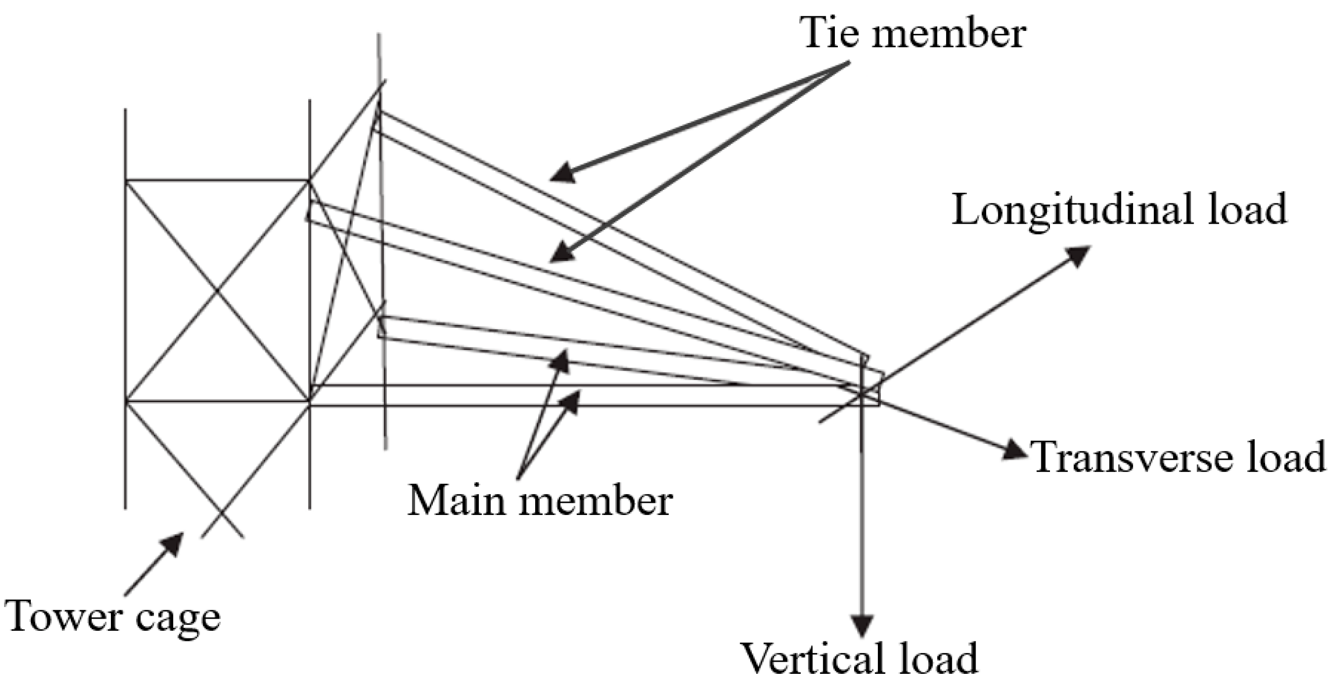
2.1. Background of Cross Arms and Latticed Transmission Towers
2.2. Materials and Design Structure
3. Creep Properties and Analyses
3.1. Creep Phenomenon in Cross Arm Structures
3.2. Creep Analysis and Properties of Cross Arms: Coupon-Scale Analysis
3.3. Creep Analysis and Properties of Cross Arms: Full-Scale Analysis
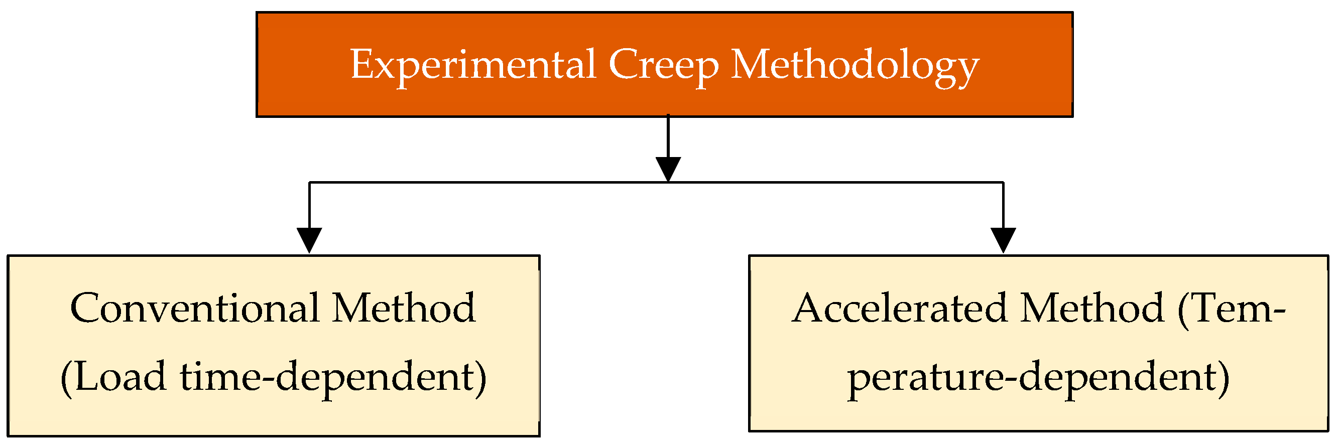
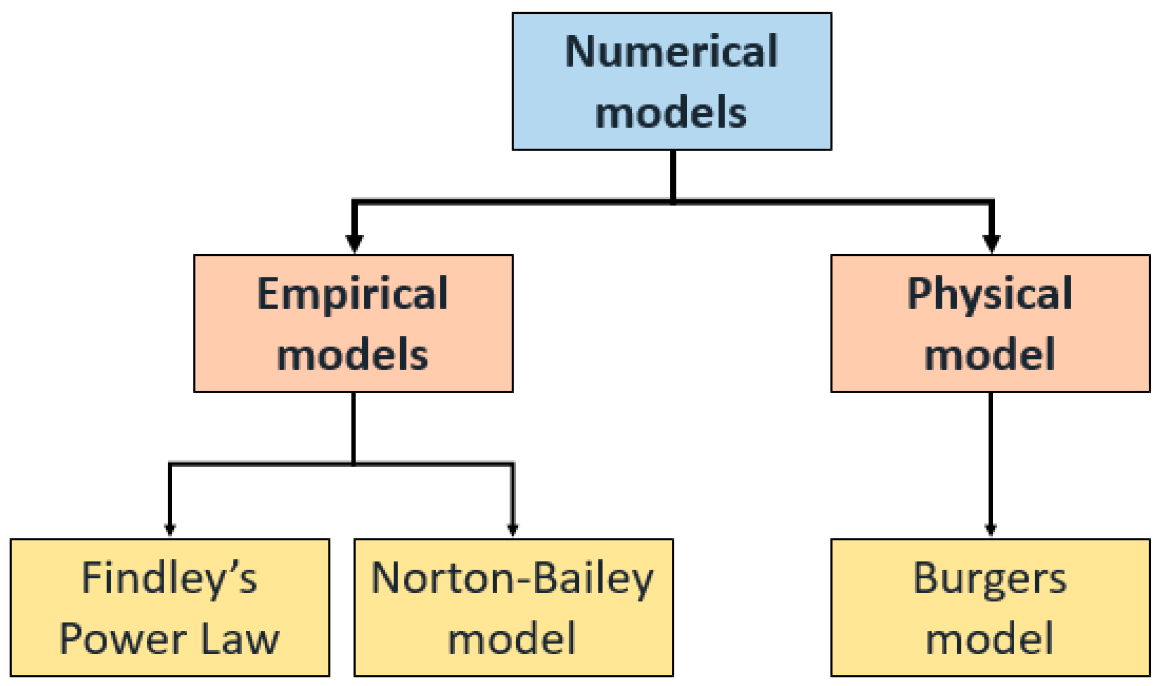
3.4. Numerical Methods of Analysing Creep Properties
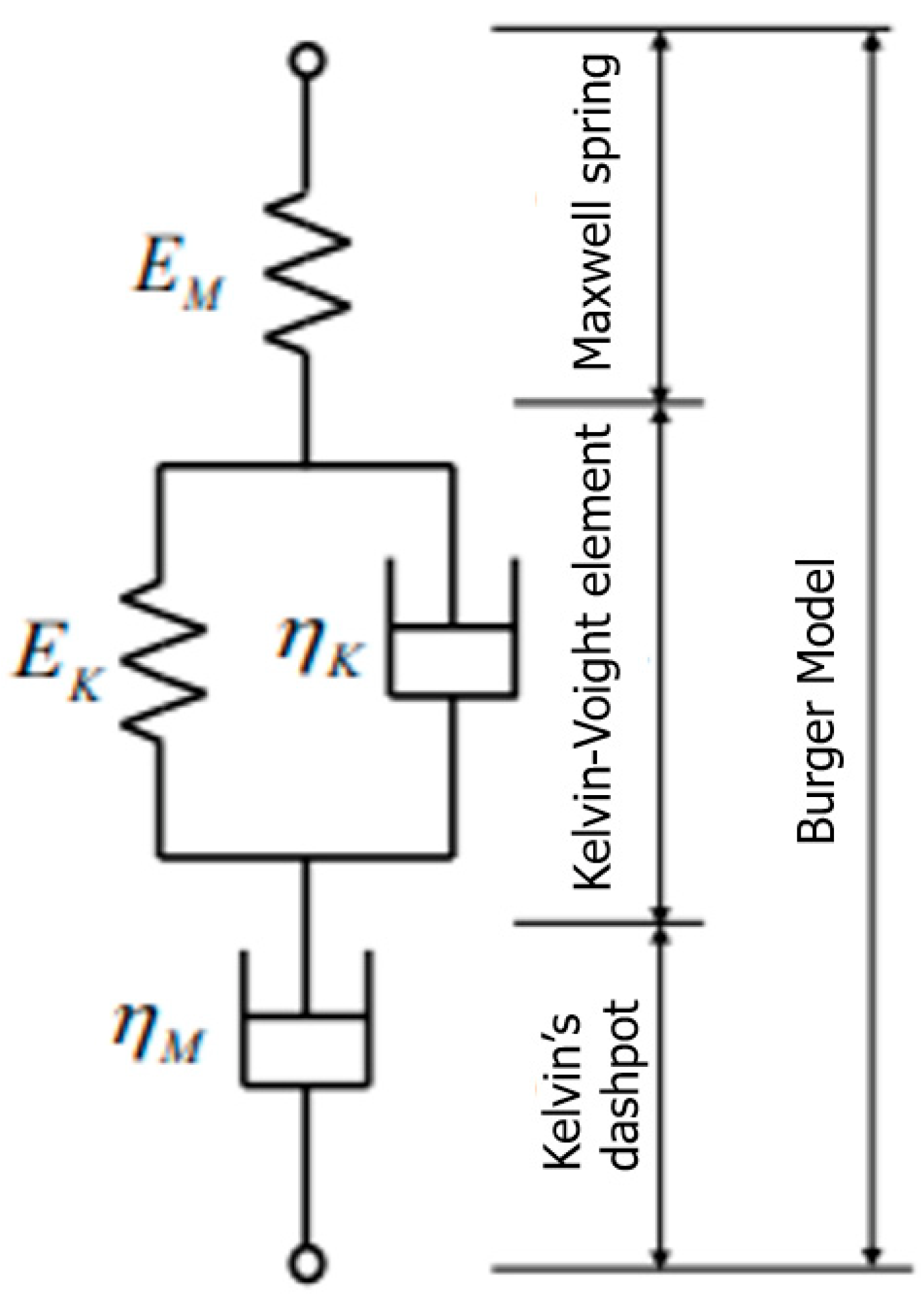
3.4.1. Burger Model
3.4.2. Findley Model
3.4.3. Norton–Bailey Model
4. Future Development of Cross Arm Structures in Latticed Transmission Towers
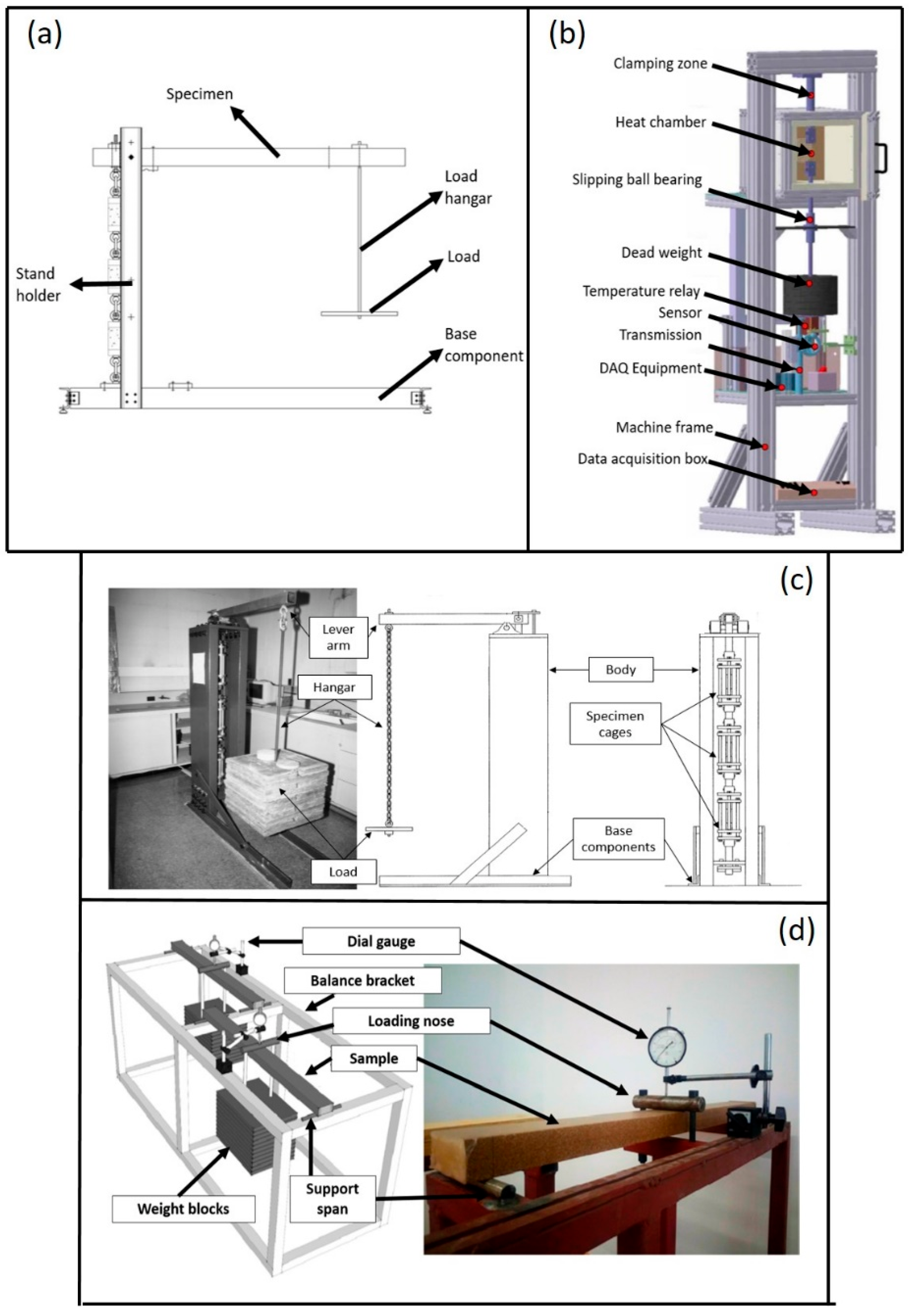
4.1. Creep Test Rigs as Testing Facilities
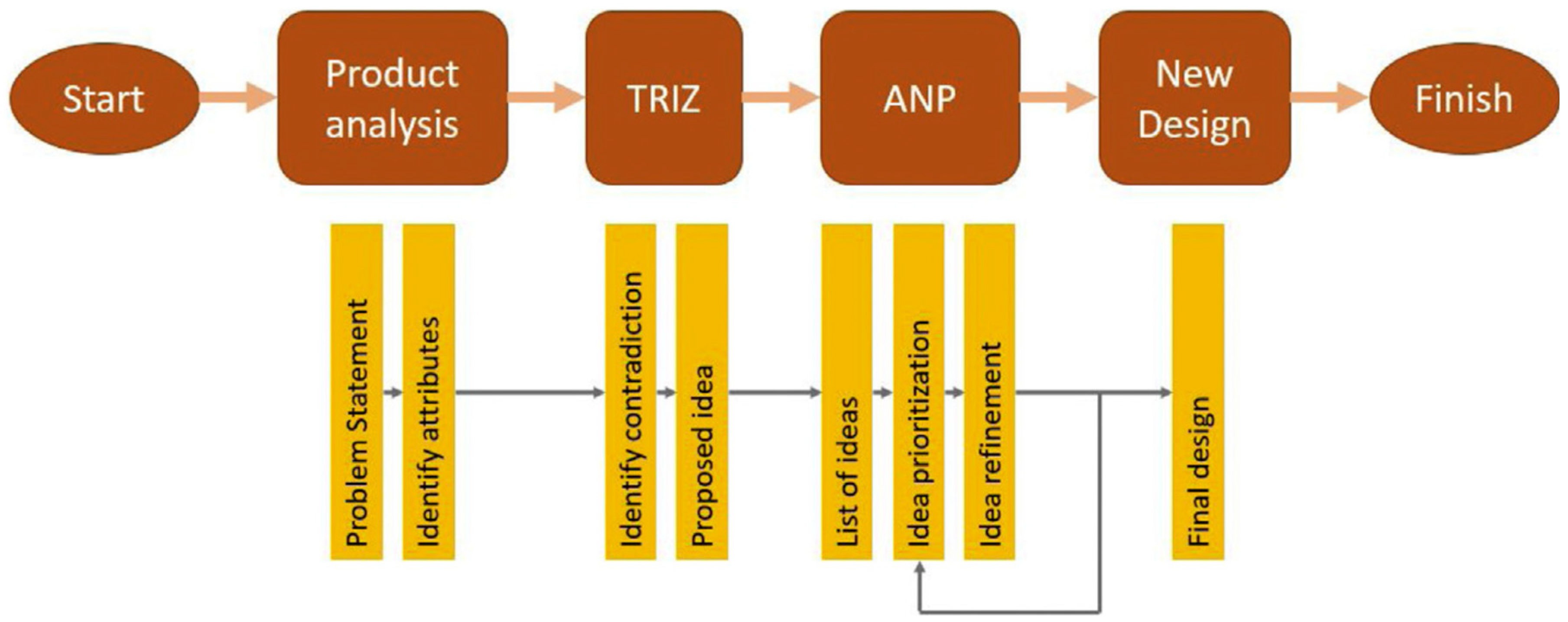
4.1.1. Theory of Inventive Problem Solving (TRIZ)
4.1.2. Morphological Chart
4.1.3. Multi-Criteria Decision Making (MCDM)
4.2. Improvements of Cross Arm Structures in Latticed Transmission Towers
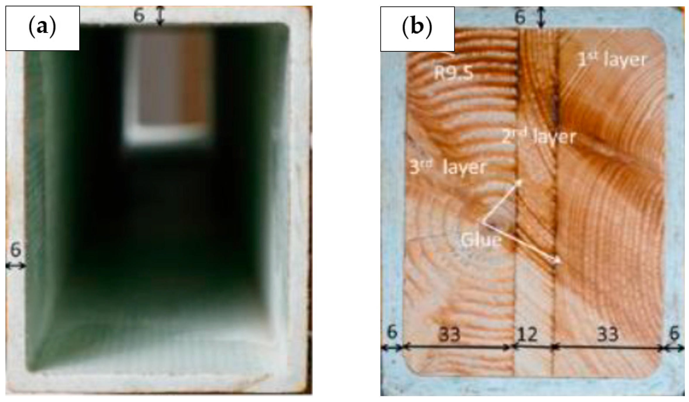
4.2.1. Sleeve Installation
4.2.2. Insertion of Core Material in the pGFRP Cross Arm Beam Profile
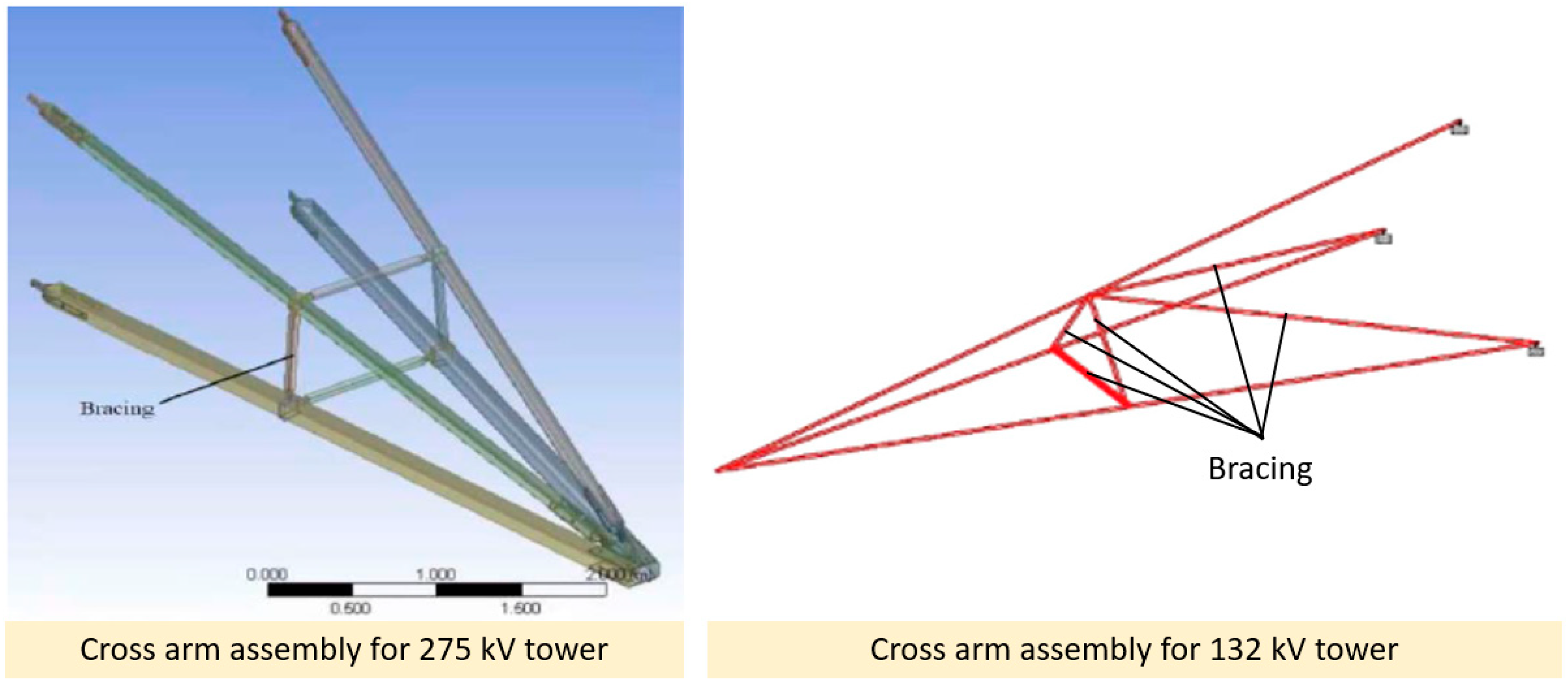
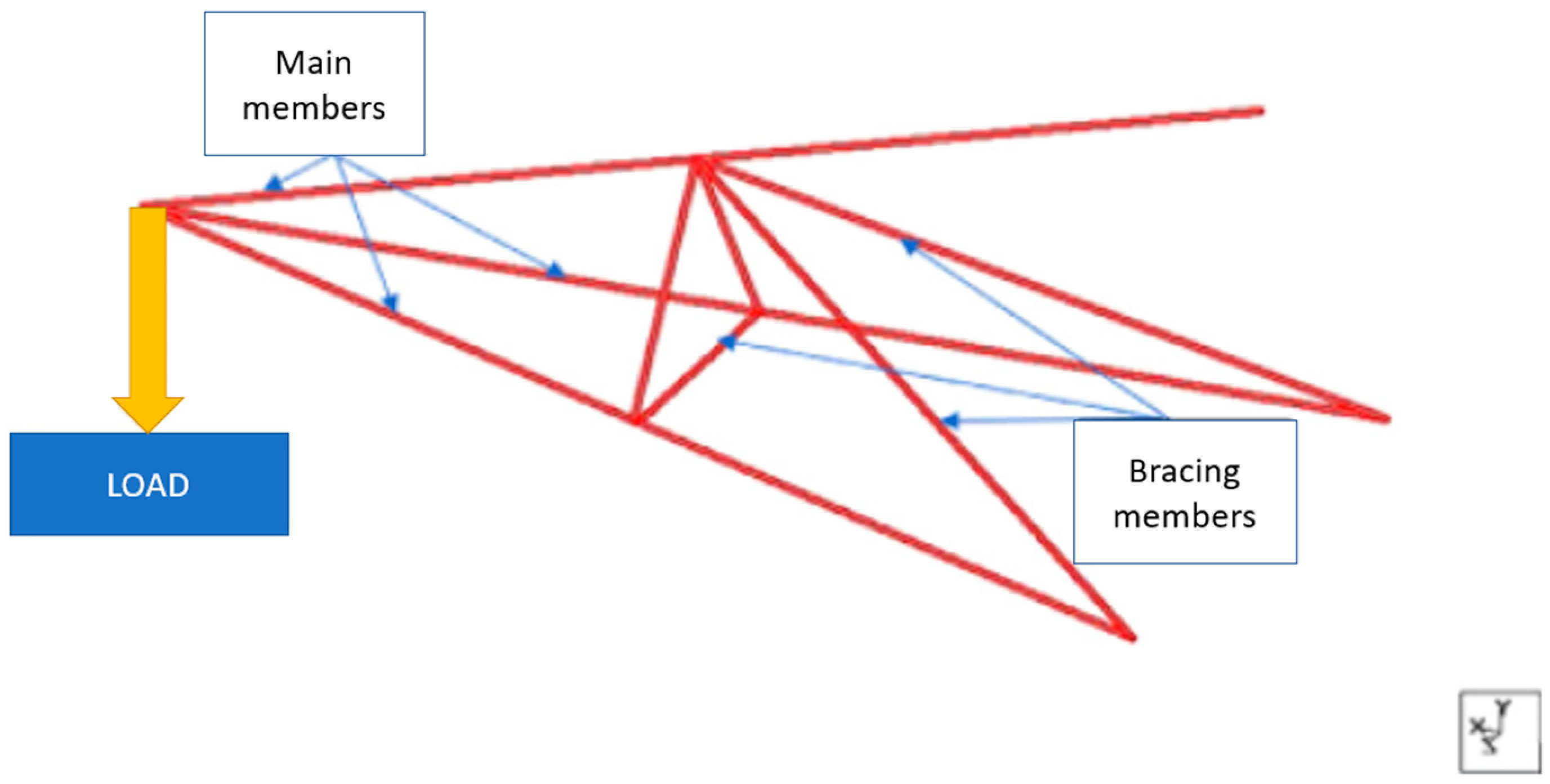
4.2.3. Retrofitting with Addition Bracing Arms
5. Conclusions
Author Contributions
Funding
Institutional Review Board Statement
Informed Consent Statement
Data Availability Statement
Acknowledgments
Conflicts of Interest
References
- Syamsir, A.; Nadhirah, A.; Mohamad, D.; Beddu, S.; Asyraf, M.R.M.; Itam, Z.; Anggraini, V. Performance Analysis of Full Assembly Glass Fiber-Reinforced Polymer Composite Cross-Arm in Transmission Tower. Polymers 2022, 14, 1563. [Google Scholar] [CrossRef]
- Mohamad, D.; Syamsir, A.; Beddu, S.; Abas, A.; Ng, F.C.; Razali, M.F.; Seman, S.A.H.A. Numerical Study of Composite Fiberglass Cross Arms under Statics Loading and Improvement with Sleeve Installation. IOP Conf. Ser. Mater. Sci. Eng. 2019, 530, 012027. [Google Scholar] [CrossRef]
- Asyraf, M.R.M.; Ishak, M.R.; Norrrahim, M.N.F.; Amir, A.L.; Nurazzi, N.M.; Ilyas, R.A.; Asrofi, M.; Rafidah, M.; Razman, M.R. Potential of Flax Fiber Reinforced Biopolymer Composites for Cross-Arm Application in Transmission Tower: A Review. Fibers Polym. 2022, 23, 853–877. [Google Scholar] [CrossRef]
- Asyraf, M.R.M.; Ishak, M.R.; Syamsir, A.; Amir, A.L.; Nurazzi, N.M.; Norrrahim, M.N.F.; Asrofi, M.; Rafidah, M.; Ilyas, R.A.; Rashid, M.Z.A.; et al. Filament-wound glass-fibre reinforced polymer composites: Potential applications for cross arm structure in transmission towers. Polym. Bull. 2022, 80, 1059–1084. [Google Scholar] [CrossRef]
- Rawi, I.M.; Rahman, M.S.A.; Ab Kadir, M.Z.A.; Izadi, M. Wood and fiberglass crossarm performance against lightning strikes on transmission towers. In Proceedings of the International Conference on Power Systems Transient (IPST), Seoul, Republic of Korea, 26–29 June 2017; pp. 1–6. [Google Scholar]
- Asyraf, M.R.M.; Ishak, M.R.; Sapuan, S.M.; Yidris, N.; Rafidah, M.; Ilyas, R.A.; Razman, M.R. Potential application of green composites for cross arm component in transmission tower: A brief review. Int. J. Polym. Sci. 2020. [Google Scholar] [CrossRef]
- Asyraf, M.R.M.; Ishak, M.R.; Razman, M.R.; Chandrasekar, M. Fundamentals of creep, testing methods and development of test rig for the full-scale crossarm: A review. J. Teknol. 2019, 81, 155–164. [Google Scholar] [CrossRef] [Green Version]
- Asyraf, M.R.M.; Ishak, M.R.; Sapuan, S.M.; Yidris, N.; Ilyas, R.A. Woods and composites cantilever beam: A comprehensive review of experimental and numerical creep methodologies. J. Mater. Res. Technol. 2020, 9, 6759–6776. [Google Scholar] [CrossRef]
- Segovia, F.; Blanchet, P.; Laghdir, A.; Cloutier, A. Mechanical behaviour of sugar maple in cantilever bending under constant and variable relative humidity conditions. Int. Wood Prod. J. 2013, 4, 225–231. [Google Scholar] [CrossRef]
- Cardoso, D.C.T.; Harries, K.A. A viscoelastic model for time-dependent behavior of pultruded GFRP. Constr. Build. Mater. 2019, 208, 63–74. [Google Scholar] [CrossRef]
- Moutee, M.; Fafard, M.; Fortin, Y.; Laghdir, A. Modeling the creep behavior of wood cantilever loaded at free end during drying. Wood Fiber Sci. 2005, 37, 521–534. [Google Scholar]
- Rafidah, M.; Asyraf, M.R.M.; Nurazzi, N.M.; Hassan, S.A.; Ilyas, R.A.; Khan, T.; Saad, W.A.A.; Rashedi, A.; Sharma, S.; Hussein, E.K. Unlocking the potential of lignocellulosic biomass in road construction: A brief review of OPF. Mater. Today Proc. 2023. [Google Scholar] [CrossRef]
- Özkılıç, Y.O.; Gemi, L.; Madenci, E.; Aksoylu, C. Effects of stirrup spacing on shear performance of hybrid composite beams produced by pultruded GFRP profile infilled with reinforced concrete. Arch. Civ. Mech. Eng. 2023, 23. [Google Scholar] [CrossRef]
- Zhang, Q.; Li, Y.; Cai, H.; Lin, X.; Yi, W.; Zhang, J. Properties comparison of high density polyethylene composites filled with three kinds of shell fibers. Results Phys. 2019, 12, 1542–1546. [Google Scholar] [CrossRef]
- Moutee, M.; Fortin, Y.; Fafard, M. A global rheological model of wood cantilever as applied to wood drying. Wood Sci. Technol. 2007, 41, 209–234. [Google Scholar] [CrossRef]
- Jiang, L.; Zhang, J.; Wolcott, M.P. Comparison of polylactide/nano-sized calcium carbonate and polylactide/montmorillonite composites: Reinforcing effects and toughening mechanisms. Polymer 2007, 48, 7632–7644. [Google Scholar] [CrossRef]
- Jorik, S.; Lion, A.; Johlitz, M. Design of the novel tensile creep experimental setup, characterisation and description of the long-term creep performance of polycarbonate. Polym. Test. 2019, 75, 151–158. [Google Scholar] [CrossRef]
- Xu, Y.; Lee, S.Y.; Wu, Q. Creep analysis of bamboo high-density polyethylene composites: Effect of interfacial treatment and fiber loading level. Polym. Compos. 2011, 32, 692–699. [Google Scholar] [CrossRef]
- Sun, N.; Frazier, C.E. Time/temperature equivalence in the dry wood creep response. Holzforschung 2007, 61, 702–706. [Google Scholar] [CrossRef]
- Fu, H.; Dun, M.; Wang, H.; Wang, W.; Ou, R.; Wang, Y.; Liu, T.; Wang, Q. Creep response of wood flour-high-density polyethylene/laminated veneer lumber coextruded composites. Constr. Build. Mater. 2020, 237, 117499. [Google Scholar] [CrossRef]
- Asyraf, M.R.M.; Ishak, M.R.; Sapuan, S.M.; Yidris, N. Conceptual design of creep testing rig for full-scale cross arm using TRIZ-Morphological chart-analytic network process technique. J. Mater. Res. Technol. 2019, 8, 5647–5658. [Google Scholar] [CrossRef]
- Sharaf, H.K.; Ishak, M.R.; Sapuan, S.M.; Yidris, N.; Fattahi, A. Experimental and numerical investigation of the mechanical behavior of full-scale wooden cross arm in the transmission towers in terms of load-deflection test. J. Mater. Res. Technol. 2020, 9, 7937–7946. [Google Scholar] [CrossRef]
- Asyraf, M.R.M.; Ishak, M.R.; Sapuan, S.M.; Yidris, N. Influence of Additional Bracing Arms as Reinforcement Members in Wooden Timber Cross-Arms on Their Long-Term Creep Responses and Properties. Appl. Sci. 2021, 11, 2061. [Google Scholar] [CrossRef]
- Asyraf, M.R.M.; Ishak, M.R.; Sapuan, S.M.; Yidris, N. Utilization of Bracing Arms as Additional Reinforcement in Pultruded Glass Fiber-Reinforced Polymer Composite Cross-Arms: Creep Experimental and Numerical Analyses. Polymers 2021, 13, 620. [Google Scholar] [CrossRef]
- Alhayek, A.; Syamsir, A.; Supian, A.B.M.; Usman, F.; Asyraf, M.R.M.; Atiqah, M.A. Flexural Creep Behaviour of Pultruded GFRP Composites Cross-Arm: A Comparative Study on the Effects of Stacking Sequence. Polymers 2022, 14, 1330. [Google Scholar] [CrossRef]
- Asyraf, M.R.M.; Ishak, M.R.; Sapuan, S.M.; Yidris, N. Comparison of Static and Long-term Creep Behaviors between Balau Wood and Glass Fiber Reinforced Polymer Composite for Cross-arm Application. Fibers Polym. 2021, 22, 793–803. [Google Scholar] [CrossRef]
- Asyraf, M.R.M.; Ishak, M.R.; Sapuan, S.M.; Yidris, N. Conceptual design of multi-operation outdoor flexural creep test rig using hybrid concurrent engineering approach. J. Mater. Res. Technol. 2020, 9, 2357–2368. [Google Scholar] [CrossRef]
- Asyraf, M.R.M.; Ishak, M.R.; Sapuan, S.M.; Yidris, N.; Ilyas, R.A.; Rafidah, M.; Razman, M.R. Evaluation of design and simulation of creep test rig for full-scale cross arm structure. Adv. Civ. Eng. 2020, 2020, 6980918. [Google Scholar] [CrossRef]
- Sharaf, H.K.; Ishak, M.R.; Sapuan, S.M.; Yidris, N. Conceptual design of the cross-arm for the application in the transmission towers by using TRIZ–morphological chart–ANP methods. J. Mater. Res. Technol. 2020, 9, 9182–9188. [Google Scholar] [CrossRef]
- Cardoso, D.C.T.; Harries, K.A.; Batista, E.D.M. Compressive strength equation for GFRP square tube columns. Compos. Part B Eng. 2014, 59, 1–11. [Google Scholar] [CrossRef]
- Selvaraj, M.; Kulkarni, S.; Babu, R.R. Analysis and experimental testing of a built-up composite cross arm in a transmission line tower for mechanical performance. Compos. Struct. 2013, 96, 1–7. [Google Scholar] [CrossRef]
- Tian, L.; Pan, H.; Ma, R.; Zhang, L.; Liu, Z. Full-scale test and numerical failure analysis of a latticed steel tubular transmission tower. Eng. Struct. 2020, 208, 109919. [Google Scholar] [CrossRef]
- Abd Halim, S.; Abu Bakar, A.H.; Illias, H.A.; Nor Hassan, N.H.; Mokhlis, H.; Terzija, V. Lightning back flashover tripping patterns on a 275/132 kV quadruple circuit transmission line in Malaysia. IET Sci. Meas. Technol. 2016, 10, 344–354. [Google Scholar] [CrossRef]
- Asyraf, M.R.M.; Ishak, M.R.; Sapuan, S.M.; Yidris, N.; Johari, A.N.; Ashraf, W.; Sharaf, H.K.; Chandrasekar, M.; Mazlan, R. Creep test rig for full-scale composite crossarm: Simulation modelling and analysis. In Proceedings of the Seminar Enau Kebangsaan, Bahau, Malaysia, 1 April 2019; pp. 34–38. [Google Scholar]
- Abd Rahman, M.S.; Ab Kadir, M.Z.A.; Ab-Rahman, M.S.; Osman, M.; Mohd Nor, S.F.; Mohd Zainuddin, N. Effects of a Crossarm Brace Application on a 275 kV Fiberglass-Reinforced Polymer Crossarm Subjected to a Lightning Impulse. Energies 2020, 13, 6248. [Google Scholar] [CrossRef]
- Nadhirah, A.; Mohamad, D.; Zainoodin, M.; Nabihah, S.; Mubin, N.; Itam, Z.; Mansor, H.; Kamal, N.M.; Muda, Z.C.; Nasional, U.T.; et al. Properties of fiberglass crossarm in transmission tower—A review. Int. J. Appl. Eng. Res. 2017, 12, 15228–15233. [Google Scholar]
- Fedor, K.; Czmoch, I. Structural Analysis of Tension Tower Subjected to Exceptional Loads during Installation of Line Conductors. Procedia Eng. 2016, 153, 136–143. [Google Scholar] [CrossRef] [Green Version]
- Jia, N.; Xia, Y.; Ma, Y.; Zhang, R. Dynamic impact load effect on suspension crossing frame at transmission tower. IOP Conf. Ser. Mater. Sci. Eng. 2020, 735, 012047. [Google Scholar] [CrossRef]
- Beddu, S.; Syamsir, A.; Arifin, Z.; Ishak, M. Creep behavior of glass fibre reinforced polymer structures in crossarms transmission line towers. AIP Conf. Proc. 2018, 020039. [Google Scholar] [CrossRef]
- Rawi, I.M.; Ab Kadir, M.Z.A. Investigation on the 132kV overhead lines lightning-related flashovers in Malaysia. In Proceedings of the International Symposium on Lightning Protection, XIII SIPDA, Balneario Camboriu, Brazil, 28 September–2 October 2015; pp. 239–243. [Google Scholar]
- Zhang, L.; Ruan, J.; Du, Z.; Zhou, W.; Li, G.; Gan, Y. Short-Term Failure Warning for Transmission Tower under Land Subsidence Condition. IEEE Access 2020, 8, 10455–10465. [Google Scholar] [CrossRef]
- Rao, N.P.; Mohan, S.J.; Lakshmanan, N. A study on failure of cross arms in transmission line towers during prototype testing. Int. J. Struct. Stab. Dyn. 2005, 5, 435–455. [Google Scholar] [CrossRef]
- Lee, S.Y.; Ng, W.L.; Hishamuddin, M.S.; Mohamed, R. The complete chloroplast genome sequence of Chengal (Neobalanocarpus heimii, Dipterocarpaceae), a durable tropical hardwood. Mitochondrial DNA Part B Resour. 2019, 4, 19–20. [Google Scholar] [CrossRef] [Green Version]
- Wong, T.M. A Dictionary of Malaysian Timbers, 2nd ed.; Forest Research Institute Malaysia: Kuala Lumpur, Malaysia, 2002. [Google Scholar]
- Chengal Wood Technical Informations. Available online: http://mtc.com.my/wizards/mtc_tud/items/report(22).php (accessed on 1 December 2022).
- Arnandha, Y.; Satyarno, I.; Awaludin, A.; Irawati, I.S.; Prasetya, Y.; Prayitno, D.A.; Winata, D.C.; Satrio, M.H.; Amalia, A. Physical and Mechanical Properties of WPC Board from Sengon Sawdust and Recycled HDPE Plastic. Procedia Eng. 2017, 171, 695–704. [Google Scholar] [CrossRef]
- Purba, C.Y.C.; Pot, G.; Viguier, J.; Ruelle, J.; Denaud, L.; Fournier, M. Mechanical properties of laminated veneer lumber (LVL) made of secondary quality oak and beech: The effect of veneer thickness. In Proceedings of the WCTE 2018—World Conference on Timber Engineering; Seoul, Republic of Korea, 20–23 August 2018. [Google Scholar]
- Ilyas, R.A.; Sapuan, S.M.; Harussani, M.M.; Hakimi, M.Y.A.Y.; Haziq, M.Z.M.; Atikah, M.S.N.; Asyraf, M.R.M.; Ishak, M.R.; Razman, M.R.; Nurazzi, N.M.; et al. Polylactic Acid (PLA) Biocomposite: Processing, Additive Manufacturing and Advanced Applications. Polymers 2021, 13, 1326. [Google Scholar] [CrossRef]
- Nurazzi, N.M.; Asyraf, M.R.M.; Khalina, A.; Abdullah, N.; Aisyah, H.A.; Rafiqah, S.A.; Sabaruddin, F.A.; Kamarudin, M.N.F.; Ilyas, R.A.; Sapuan, S.M. A Review on Natural Fiber Reinforced Polymer Composite for Bullet Proof and Ballistic Applications. Polymers 2021, 13, 646. [Google Scholar] [CrossRef]
- Nurazzi, N.M.; Asyraf, M.R.M.; Fatimah Athiyah, S.; Shazleen, S.S.; Rafiqah, S.A.; Harussani, M.M.; Kamarudin, S.H.; Razman, M.R.; Rahmah, M.; Zainudin, E.S.; et al. A Review on Mechanical Performance of Hybrid Natural Fiber Polymer Composites for Structural Applications. Polymers 2021, 13, 2170. [Google Scholar] [CrossRef]
- Asyraf, M.R.M.; Rafidah, M.; Ebadi, S.; Azrina, A.; Razman, M.R. Mechanical properties of sugar palm lignocellulosic fibre reinforced polymer composites: A review. Cellulose 2022, 29, 6493–6516. [Google Scholar] [CrossRef]
- Asyraf, M.R.M.; Syamsir, A.; Supian, A.B.M.; Usman, F.; Ilyas, R.A.; Nurazzi, N.M.; Norrrahim, M.N.F.; Razman, M.R.; Zakaria, S.Z.S.; Sharma, S.; et al. Sugar Palm Fibre-Reinforced Polymer Composites: Influence of Chemical Treatments on Its Mechanical Properties. Materials 2022, 15, 3852. [Google Scholar] [CrossRef]
- Fairuz, A.M.; Sapuan, S.M.; Zainudin, E.S.; Jaafar, C.N.A. Polymer composite manufacturing using a pultrusion process: A review. Am. J. Appl. Sci. 2014, 11, 1798–1810. [Google Scholar] [CrossRef]
- Wong, K.J.; Yousif, B.F.; Low, K.O.; Ng, Y.; Tan, S.L. Effects of fillers on the fracture behaviour of particulate polyester composites. J. Strain Anal. Eng. Des. 2010, 45, 67–78. [Google Scholar] [CrossRef] [Green Version]
- Yao, H.; Xuan, F.; Wang, Z.; Tu, S. A review of creep analysis and design under multi-axial stress states. Nucl. Eng. Des. 2007, 237, 1969–1986. [Google Scholar] [CrossRef]
- Kaboorani, A.; Blanchet, P.; Laghdir, A. A rapid method to assess viscoelastic and mechanosorptive creep in wood. Wood Fiber Sci. 2013, 45, 1–13. [Google Scholar]
- Holzer, S.M.; Loferski, J.R.; Dillard, D.A. a review of creep in wood: Concepts relevant to develop long-term behavior predictions for wood structures. Wood Fiber Sci. 1989, 1, 376–392. [Google Scholar]
- Taniguchi, Y.; Ando, K.; Yamamoto, H. Determination of three-dimensional viscoelastic compliance in wood by tensile creep test. J. Wood Sci. 2010, 56, 82–84. [Google Scholar] [CrossRef]
- Hunt, J.F.; Zhang, H.; Huang, Y. Analysis of cantilever-beam bending stress relaxation properties of thin wood composites. BioResources 2015, 10, 3131–3145. [Google Scholar] [CrossRef] [Green Version]
- Tajvidi, M.; Falk, R.H.; Hermanson, J.C. Time-temperature superposition principle applied to a kenaf-fiber/high- density polyethylene composite. J. Appl. Polym. Sci. 2005, 97, 1995–2004. [Google Scholar] [CrossRef]
- Ponsot, B.; Valentin, D.; Bunsell, A.R. The effects of time, temperature and stress on the long-term behaviour of CFRP. Compos. Sci. Technol. 1989, 35, 75–94. [Google Scholar] [CrossRef]
- Bueno, B.S.; Costanzi, M.A.; Zornberg, J.G. Conventional and accelerated creep tests on nonwoven needle-punched geotextiles. Geosynth. Int. 2005, 12, 276–287. [Google Scholar] [CrossRef]
- Hadid, M.; Guerira, B.; Bahri, M.; Zouani, K. The creep master curve construction for the polyamide 6 by the stepped isostress method. Mater. Res. Innov. 2014, 18, S6-336–S6-339. [Google Scholar] [CrossRef]
- Hao, A.; Chen, Y.; Chen, J.Y. Creep and recovery behavior of kenaf/polypropylene nonwoven composites. J. Appl. Polym. Sci. 2014, 131, 8864–8874. [Google Scholar] [CrossRef]
- Anand, A.; Banerjee, P.; Prusty, R.K.; Chandra Ray, B. Lifetime Prediction of Nano-Silica based Glass Fibre/Epoxy composite by Time Temperature Superposition Principle. IOP Conf. Ser. Mater. Sci. Eng. 2018, 338, 012020. [Google Scholar] [CrossRef] [Green Version]
- Nakai, T.; Toba, K.; Yamamoto, H. Creep and stress relaxation behavior for natural cellulose crystal of wood cell wall under uniaxial tensile stress in the fiber direction. J. Wood Sci. 2018, 64, 745–750. [Google Scholar] [CrossRef] [Green Version]
- Jirásek, M. Properties of creep compliance functions and their relation to retardation spectra. In Proceedings of the 10th International Conference on Mechanics and Physics of Creep, Shrinkage, and Durability of Concrete and Concrete Structures (CONCREEP 10), Vienna, Austria, 21–23 September 2015; American Society of Civil Engineers: Reston, VA, USA, 2015; pp. 1269–1278. [Google Scholar]
- Asyraf, M.R.M.; Nurazzi, N.M.; Norrrahim, M.N.F.; Hazrati, K.Z.; Ghani, A.; Sabaruddin, F.A.; Lee, S.H.; Shazleen, S.S.; Razman, M.R. Thermal properties of oil palm lignocellulosic fibre reinforced polymer composites: A comprehensive review on thermogravimetry analysis. Cellulose 2023. [Google Scholar] [CrossRef]
- Johari, A.N.; Ishak, M.R.; Leman, Z.; Yusoff, M.Z.M.; Asyraf, M.R.M. Influence of CaCO3 in pultruded glass fiber/unsaturated polyester resin composite on flexural creep behavior using conventional and time-temperature superposition principle methods. Polimery/Polymers 2020, 65, 792–800. [Google Scholar] [CrossRef]
- Syamsir, A.; Amat, A.H.; Usman, F.; Itam, Z.; Kamal, N.L.M.; Zahari, N.M.; Chairi, M.; Imani, R. Effect of fiber orientation on ultimate tensile strength and Young’s modulus of fabricated glass fiber reinforced polymer plates. AIP Conf. Proc. 2021, 2339, 020123. [Google Scholar] [CrossRef]
- Asyraf, M.R.M.; Syamsir, A.; Zahari, N.M.; Supian, A.B.M.; Usman, F.; Itam, Z. Effect of Stacking Sequence on Long-Term Creep Performance of Pultruded GFRP Composites. Polymers 2022, 14, 4064. [Google Scholar] [CrossRef]
- Sanyang, M.L.; Sapuan, S.M.; Jawaid, M.; Ishak, M.R.; Sahari, J. Effect of sugar palm-derived cellulose reinforcement on the mechanical and water barrier properties of sugar palm starch biocomposite films. BioResources 2016, 11, 4134–4145. [Google Scholar] [CrossRef] [Green Version]
- Gemi, L.; Madenci, E.; Özkılıç, Y.O. Experimental, analytical and numerical investigation of pultruded GFRP composite beams infilled with hybrid FRP reinforced concrete. Eng. Struct. 2021, 244. [Google Scholar] [CrossRef]
- Cho, D.; Lee, H.S.; Han, S.O. Effect of fiber surface modification on the interfacial and mechanical properties of kenaf fiber-reinforced thermoplastic and thermosetting polymer composites. Compos. Interfaces 2009, 16, 711–729. [Google Scholar] [CrossRef]
- Hoseinzadeh, F.; Zabihzadeh, S.M.; Dastoorian, F. Creep behavior of heat treated beech wood and the relation to its chemical structure. Constr. Build. Mater. 2019, 226, 220–226. [Google Scholar] [CrossRef]
- Asyraf, M.R.M.; Rafidah, M.; Ishak, M.R.; Sapuan, S.M.; Yidris, N.; Ilyas, R.A.; Razman, M.R. Integration of TRIZ, Morphological Chart and ANP method for development of FRP composite portable fire extinguisher. Polym. Compos. 2020, 41, 2917–2932. [Google Scholar] [CrossRef]
- Alias, A.H.; Norizan, M.N.; Sabaruddin, F.A.; Asyraf, M.R.M.; Norrrahim, M.N.F.; Ilyas, A.R.; Kuzmin, A.M.; Rayung, M.; Shazleen, S.S.; Nazrin, A.; et al. Hybridization of MMT/Lignocellulosic Fiber Reinforced Polymer Nanocomposites for Structural Applications: A Review. Coatings 2021, 11, 1355. [Google Scholar] [CrossRef]
- Azman, M.A.; Asyraf, M.R.M.; Khalina, A.; Petrů, M.; Ruzaidi, C.M.; Sapuan, S.M.; Wan Nik, W.B.; Ishak, M.R.; Ilyas, R.A.; Suriani, M.J. Natural Fiber Reinforced Composite Material for Product Design: A Short Review. Polymers 2021, 13, 1917. [Google Scholar] [CrossRef]
- Atiqah, A.; Maleque, M.A.; Jawaid, M.; Iqbal, M. Development of kenaf-glass reinforced unsaturated polyester hybrid composite for structural applications. Compos. Part B Eng. 2014, 56, 68–73. [Google Scholar] [CrossRef]
- Acharya, S.K. Soma Dalbehera Study on mechanical properties of natural fiber reinforced woven jute-glass hybrid epoxy composites. Adv. Polym. Sci. Technol. 2014, 4, 1–6. [Google Scholar]
- Huang, H.; Yao, Y.; Liang, C.; Ye, Y. Experimental study on cyclic performance of steel-hollow core partially encased composite spliced frame beam. Soil Dyn. Earthq. Eng. 2022, 163, 107499. [Google Scholar] [CrossRef]
- Zhang, H.; Li, L.; Ma, W.; Luo, Y.; Li, Z.; Kuai, H. Effects of welding residual stresses on fatigue reliability assessment of a PC beam bridge with corrugated steel webs under dynamic vehicle loading. Structures 2022, 45, 1561–1572. [Google Scholar] [CrossRef]
- Xiao, X.; Zhang, H.; Li, Z.; Chen, F. Effect of Temperature on the Fatigue Life Assessment of Suspension Bridge Steel Deck Welds under Dynamic Vehicle Loading. Math. Probl. Eng. 2022, 2022, 7034588. [Google Scholar] [CrossRef]
- Movahedi-Rad, A.V.; Keller, T.; Vassilopoulos, A.P. Creep effects on tension-tension fatigue behavior of angle-ply GFRP composite laminates. Int. J. Fatigue 2019, 123, 144–156. [Google Scholar] [CrossRef]
- Feng, S.H.; Zhao, Y.K. The summary of wood stress relaxation properties and its influencing factors. Wood Proc. Mach. 2010, 25, 39–40. [Google Scholar]
- Zhang, Z.; Zhang, W.; Zhai, Z.J.; Chen, Q.Y. Evaluation of various turbulence models in predicting airflow and turbulence in enclosed environments by CFD: Part 2—Comparison with experimental data from literature. HVAC R Res. 2007, 13, 871–886. [Google Scholar] [CrossRef]
- Bastami, M.; Ahmady Jazany, R. Development of Eccentrically Interconnected Braced Frame (EIC-BF) for seismic regions. Thin-Walled Struct. 2018, 131, 451–463. [Google Scholar] [CrossRef]
- Asyraf, M.R.M.; Ishak, M.R.; Sapuan, S.M.; Yidris, N.; Shahroze, R.M.; Johari, A.N.; Rafidah, M.; Ilyas, R.A. Creep test rig for cantilever beam: Fundamentals, prospects and present views. J. Mech. Eng. Sci. 2020, 14, 6869–6887. [Google Scholar] [CrossRef]
- Chandra, P.K.; Sobral, P.J.D.A. Calculation of viscoelastic properties of edible films: Application of three models. Ciência Tecnol. Aliment. 2006, 20, 250–256. [Google Scholar] [CrossRef]
- Wong, S.; Shanks, R. Creep behaviour of biopolymers and modified flax fibre composites. Compos. Interfaces 2008, 15, 131–145. [Google Scholar] [CrossRef]
- Findley, W.N.; Lai, J.S.; Onaran, K.; Christensen, R.M. Creep and Relaxation of Nonlinear Viscoelastic Materials With an Introduction to Linear Viscoelasticity. J. Appl. Mech. 2010, 44, 364. [Google Scholar] [CrossRef] [Green Version]
- Yang, Z.; Wang, H.; Ma, X.; Shang, F.; Ma, Y.; Shao, Z.; Hou, D. Flexural creep tests and long-term mechanical behavior of fiber-reinforced polymeric composite tubes. Compos. Struct. 2018, 193, 154–164. [Google Scholar] [CrossRef]
- Scott, D.W.; Zureick, A.-H. Compression creep of a pultruded E-glass/vinylester composite. Compos. Sci. Technol. 1998, 58, 1361–1369. [Google Scholar] [CrossRef]
- Findley, W.N. Creep characteristics of plastics. Symp. Plast. ASTM 1944, 118, 118–134. [Google Scholar]
- Pérez, C.J.; Alvarez, V.A.; Vázquez, A. Creep behaviour of layered silicate/starch-polycaprolactone blends nanocomposites. Mater. Sci. Eng. A 2008, 480, 259–265. [Google Scholar] [CrossRef]
- Yang, J.L.; Zhang, Z.; Schlarb, A.K.; Friedrich, K. On the characterization of tensile creep resistance of polyamide 66 nanocomposites. Part II: Modeling and prediction of long-term performance. Polymer 2006, 47, 6745–6758. [Google Scholar] [CrossRef]
- Ahmad, M.I.M.; Curiel Sosa, J.L.; Rongong, J.A. Characterisation of creep behaviour using the power law model in copper alloy. J. Mech. Eng. Sci. 2017, 11, 2503–2510. [Google Scholar] [CrossRef]
- May, D.L.; Gordon, A.P.; Segletes, D.S. The Application of the Norton-Bailey Law for Creep Prediction through Power Law Regression. In Proceedings of the ASME Turbo Expo 2013: Turbine Technical Conference and Exposition, San Antonio, TX, USA, 3–7 June 2013; p. V07AT26A005. [Google Scholar] [CrossRef] [Green Version]
- Mohammadizadeh, M.; Fidan, I.; Allen, M.; Imeri, A. Creep behavior analysis of additively manufactured fiber-reinforced components. Int. J. Adv. Manuf. Technol. 2018, 99, 1225–1234. [Google Scholar] [CrossRef]
- Li, X.; Liu, W.; Fang, H.; Huo, R.; Wu, P. Flexural creep behavior and life prediction of GFRP-balsa sandwich beams. Compos. Struct. 2019, 224, 111009. [Google Scholar] [CrossRef]
- Krauklis, A.E.; Karl, C.W.; Gagani, A.I.; Jørgensen, J.K. Composite material recycling technology—State-of-the-art and sustainable development for the 2020s. J. Compos. Sci. 2021, 5, 28. [Google Scholar] [CrossRef]
- Madenci, E.; Özkılıç, Y.O.; Aksoylu, C.; Asyraf, M.R.M.; Syamsir, A.; Supian, A.B.M.; Mamaev, N. Buckling Analysis of CNT-Reinforced Polymer Composite Beam Using Experimental and Analytical Methods. Materials 2023, 16, 614. [Google Scholar] [CrossRef]
- Rashedi, A.; Gul, N.; Hussain, M.; Hadi, R.; Khan, N.; Nadeem, S.G.; Khanam, T.; Asyraf, M.R.M.; Kumar, V. Life cycle environmental sustainability and cumulative energy assessment of biomass pellets biofuel derived from agroforest residues. PLoS ONE 2022, 17, e0275005. [Google Scholar] [CrossRef]
- Bahrain, S.H.K.; Masdek, N.R.N.; Mahmud, J.; Mohammed, M.N.; Sapuan, S.M.; Ilyas, R.A.; Mohamed, A.; Shamseldin, M.A.; Abdelrahman, A.; Asyraf, M.R.M. Morphological, Physical, and Mechanical Properties of Sugar-Palm (Arenga pinnata (Wurmb) Merr.)-Reinforced Silicone Rubber Biocomposites. Materials 2022, 15, 4062. [Google Scholar] [CrossRef]
- Ali, S.S.S.; Razman, M.R.; Awang, A.; Asyraf, M.R.M.; Ishak, M.R.; Ilyas, R.A.; Lawrence, R.J. Critical Determinants of Household Electricity Consumption in a Rapidly Growing City. Sustainability 2021, 13, 4441. [Google Scholar] [CrossRef]
- Roslan, Z.B.; Ramli, Z.; Razman, M.R.; Asyraf, M.R.M.; Ishak, M.R.; Ilyas, R.A.; Nurazzi, N.M. Reflections on Local Community Identity by Evaluating Heritage Sustainability Protection in Jugra, Selangor, Malaysia. Sustainability 2021, 13, 8705. [Google Scholar] [CrossRef]
- Asyraf, M.R.M.; Syamsir, A.; Zahari, N.M.; Supian, A.B.M.; Ishak, M.R.; Sapuan, S.M.; Sharma, S.; Rashedi, A.; Razman, M.R.; Zakaria, S.Z.S.; et al. Product Development of Natural Fibre-Composites for Various Applications: Design for Sustainability. Polymers 2022, 14, 920. [Google Scholar] [CrossRef]
- Chowdhury, T.; Hasan, S.; Chowdhury, H.; Hasnat, A.; Rashedi, A.; Asyraf, M.R.M.; Hassan, M.Z.; Sait, S.M. Sizing of an Island Standalone Hybrid System Considering Economic and Environmental Parameters: A Case Study. Energies 2022, 15, 5940. [Google Scholar] [CrossRef]
- Asyraf, M.R.M.; Ishak, M.R.; Syamsir, A.; Nurazzi, N.M.; Sabaruddin, F.A.; Shazleen, S.S.; Norrrahim, M.N.F.; Rafidah, M.; Ilyas, R.A.; Rashid, M.Z.A.; et al. Mechanical properties of oil palm fibre-reinforced polymer composites: A review. J. Mater. Res. Technol. 2022, 17, 33–65. [Google Scholar] [CrossRef]
- Asyraf, M.R.M.; Ishak, M.R.; Norrrahim, M.N.F.; Nurazzi, N.M.; Shazleen, S.S.; Ilyas, R.A.; Rafidah, M.; Razman, M.R. Recent advances of thermal properties of sugar palm lignocellulosic fibre reinforced polymer composites. Int. J. Biol. Macromol. 2021, 193, 1587–1599. [Google Scholar] [CrossRef]
- Johari, A.N.; Ishak, M.R.; Leman, Z.; Yusoff, M.Z.M.; Asyraf, M.R.M. Creep behaviour monitoring of short-term duration for fiber-glass reinforced composite cross-arms with unsaturated polyester resin samples using conventional analysis. J. Mech. Eng. Sci. 2020, 14, 7361–7368. [Google Scholar] [CrossRef]
- Ahmed, U.; Janjua, F.; Zhang, X. Applications and Design of Composite Insulated Cross Arms. In Proceedings of the 2022 IEEE/PES Transmission and Distribution Conference and Exposition (T&D), New Orleans, LA, USA, 25–28 April 2022; pp. 1–5. [Google Scholar]
- Jiang, J.; Erik Valentine, B.; Lu, J.; Niemz, P. Time dependence of the orthotropic compression Young’s moduli and Poisson’s ratios of Chinese fir wood. Holzforschung 2016, 70, 1093–1101. [Google Scholar] [CrossRef] [Green Version]
- Mazani, N.; Sapuan, S.M.; Sanyang, M.L.; Atiqah, A.; Ilyas, R.A. Design and Fabrication of a Shoe Shelf From Kenaf Fiber Reinforced Unsaturated Polyester Composites. In Lignocellulose for Future Bioeconomy; Ariffin, H., Sapuan, S.M., Hassan, M.A., Eds.; Elsevier Inc.: Amsterdam, The Netherland, 2019; pp. 315–332. ISBN 9780128163542. [Google Scholar]
- Ashby, M.F. Materials Selection in Mechanical Design, 5th ed.; Elsevier: Amsterdam, The Netherlands, 2011; Volume 86, ISBN 9781856176637. [Google Scholar]
- Azammi, A.M.N.; Sapuan, S.M.; Ishak, M.R.; Sultan, M.T.H. Conceptual design of automobile engine rubber mounting composite using TRIZ-Morphological chart-analytic network process technique. Def. Technol. 2018, 14, 268–277. [Google Scholar] [CrossRef]
- Mansor, M.R.; Sapuan, S.M.; Hambali, A. Conceptual design of kenaf polymer composites automotive spoiler using TRIZ and Morphology Chart methods. Appl. Mech. Mater. 2015, 761, 63–67. [Google Scholar] [CrossRef]
- Ghani, J.A.; Natasha, A.R.; Che Hassan, C.H.; Syarif, J. TRIZ approach for machining process innovation in cryogenic environment. Int. J. Mater. Prod. Technol. 2016, 53, 286–297. [Google Scholar] [CrossRef]
- Sapuan, S.M. Using the morphological chart technique for the design of polymeric-based composite automotive pedals. Discov. Innov. 2006, 18, 311–317. [Google Scholar] [CrossRef]
- Shaharuzaman, M.A.; Sapuan, S.M.; Mansor, M.R.; Zuhri, M.Y.M. Conceptual design of natural fiber composites as a side-door impact beam using hybrid approach. J. Renew. Mater. 2020, 8, 549–563. [Google Scholar] [CrossRef]
- Li, Y.; Beeton, R.J.S.; Sigler, T.; Halog, A. Modelling the transition toward urban sustainability: A case study of the industrial city of Jinchang, China. J. Clean. Prod. 2016, 134, 22–30. [Google Scholar] [CrossRef] [Green Version]
- San, Y.T.; Jin, Y.T.; Li, S.C. TRIZ: Systematic Innovation in Manufacturing; Firstfruit Sdn. Bhd.: Selangor, Malaysia, 2011; ISBN 9838040266. [Google Scholar]
- Cascini, G.; Rissone, P.; Rotini, F.; Russo, D. Systematic design through the integration of TRIZ and optimization tools. Procedia Eng. 2011, 9, 674–679. [Google Scholar] [CrossRef] [Green Version]
- Ullman, D. The mechanical design process. Des. Stud. 2003, 15, 448. [Google Scholar] [CrossRef]
- Ulrich, K.; Eppinger, S. Product Design and Development; McGraw Hill: New York, NY, USA, 1995. [Google Scholar]
- Salit, M.S.; Syed, M.; Molla, A.; Ali, L. Conceptual Design of an Automotive Composite Brake Pedal. Suranaree J. Sci. Technol. 2005, 12, 173–177. [Google Scholar]
- Abidin, M.Z.; Rusli, R.; Shariff, A.M. Technique for Order Performance by Similarity to Ideal Solution (TOPSIS)-entropy Methodology for Inherent Safety Design Decision Making Tool. Procedia Eng. 2016, 148, 1043–1050. [Google Scholar] [CrossRef] [Green Version]
- Hambali, A.; Amira Farhana, M.T. Development of integrated analytic network process (Anp) and theory of inventive problem solving (Triz) in the conceptual design selection. J. Eng. Sci. Technol. 2018, 13, 2716–2733. [Google Scholar]
- Tiwari, V.; Jain, P.K.; Tandon, P. Product design concept evaluation using rough sets and VIKOR method. Adv. Eng. Informatics 2016, 30, 16–25. [Google Scholar] [CrossRef]
- Syamsir, A.; Mohamad, D.; Beddu, S.; Itam, Z.; Sadon, S.N. A review on durability and degradation of glass fiber reinforced polymer structures. Int. J. Adv. Sci. Technol. 2019, 28, 218–226. [Google Scholar]
- Syamsir, A. TNB Seed Fund Report: Research and Development of Flexural Creep and Long-Term Mechanical Behavior Testing of Existing Composite Crossarm for Life Span Prediction. In AIP Conference Proceedings; AIP Publishing LLC: Melville, NY, USA, 2020. [Google Scholar]
- Qin, Q.; Wang, T.J. Low-velocity impact response of fully clamped metal foam core sandwich beam incorporating local denting effect. Compos. Struct. 2013, 96, 346–356. [Google Scholar] [CrossRef]
- Zhang, L.; Liu, W.; Wang, L.; Ling, Z. Mechanical behavior and damage monitoring of pultruded wood-cored GFRP sandwich components. Compos. Struct. 2019, 215, 502–520. [Google Scholar] [CrossRef]
- Amir, A.L.; Ishak, M.R.; Yidris, N.; Zuhri, M.Y.M.; Asyraf, M.R.M. Potential of Honeycomb-Filled Composite Structure in Composite Cross-Arm Component: A Review on Recent Progress and Its Mechanical Properties. Polymers 2021, 13, 1341. [Google Scholar] [CrossRef]
- Amir, A.L.; Ishak, M.R.; Yidris, N.; Zuhri, M.Y.M.; Asyraf, M.R.M. Advances of composite cross arms with incorporation of material core structures: Manufacturability, recent progress and views. J. Mater. Res. Technol. 2021, 13, 1115–1131. [Google Scholar] [CrossRef]
- Klasson, A.; Crocetti, R.; Hansson, E.F. Slender steel columns: How they are affected by imperfections and bracing stiffness. Structures 2016, 8, 35–43. [Google Scholar] [CrossRef]
- Patil, D.M.; Sangle, K.K. Seismic behaviour of different bracing systems in high rise 2-D steel buildings. Structures 2015, 3, 282–305. [Google Scholar] [CrossRef]
- Chang, E.; Dover, W.D. Characteristic parameters for stress distribution along the intersection of tubular Y, T, X and DT joints. J. Strain Anal. Eng. Des. 2001, 36, 323–339. [Google Scholar] [CrossRef]
- Guo, Y.L.; Fu, P.P.; Zhou, P.; Tong, J.Z. Elastic buckling and load resistance of a single cross-arm pre-tensioned cable stayed buckling-restrained brace. Eng. Struct. 2016, 126, 516–530. [Google Scholar] [CrossRef]
- Mohamad, D.; Syamsir, A.; Itam, Z.; Bakar, H.A.; Abas, A.; Ng, F.C.; Razali, M.F.; Seman, S.A.H.A. Numerical Simulation on the Statics Deformation Study of Composite Cross Arms of Different Materials and Configurations. IOP Conf. Ser. Mater. Sci. Eng. 2019, 530, 012028. [Google Scholar] [CrossRef]


| Refs. | Mode of Study | Research | Findings |
|---|---|---|---|
| [21,28] | Cross arm test rig development | Conceptual design of test rig for full-scale cross arms. |
|
| [27] | Conceptual design of flexural creep test rig. | ||
| [29] | Design of GFRP cross arms | Conceptual design of bracing for composite cross arms. |
|
| [30] | Experiments | Compressive test for GFRP square-tube columns. |
|
| [31] | Mechanical tests on pGFRP composite cross arms. |
|
| Material | Density kg/m3 | Elastic Modulus (GPa) | Rupture Modulus (MPa) | Compression (MPa) | Shear Strength (MPa) | Refs. | |
|---|---|---|---|---|---|---|---|
| Parallel to Grain | Perpendicular to Grain | ||||||
| Chengal | 915–980 | 19.60 | 149.0 | 75.0 | 12.0 | 14.0 | [45] |
| Recycled HDPE/Wood flour composites | 900 | 32.63 | 40.9 | 44.97 | 43.91 | 27.36 | [46] |
| Laminated veneer lumber | 590 | 6.06 | 55.0 | - | - | 14.14 | [47] |
| pGFRP Composite Cross Arm Fabric Orientation (°) | Ultimate Flexural Strength (MPa) | Refs. |
|---|---|---|
| 45°/0°/45° | 267.88 | [13] |
| 45°/−45°/90°/0°/45° | 175.21 | |
| 45°/−45°/0°/90°/0°/90°/0° | 355.96 | |
| 0°/45°/0°/−45°/0°/−45°/0°/45°/0° | 436.29 | |
| 45°/−45°/0°/0°/0°/0°/0°/0°/−45°/45° | 289.07 | |
| ±45°/90°/0°/±45° | 242.60 | [14] |
| ±45°/0°/90°/0°/90°/0° | 399.05 | |
| 45°/−45°/90°/0°/45° | 421.35 | [27] |
| Materials | Density (kg/m3) | Texture | Tensile Strength (MPa) | Young’s Modulus (GPa) | Rupture Modulus (MPa) | Refs. |
|---|---|---|---|---|---|---|
| Chengal Wood | 915–980 | Fine and even with deeply interlocked grain | 149.00 | 19.6 | 149.0 | [54] |
| pGFRP Composites | 850–1155 | Fine, homogenous, and unidirectional fibre along the matrix | 429 | 34.0 | 858.0 | [1] |
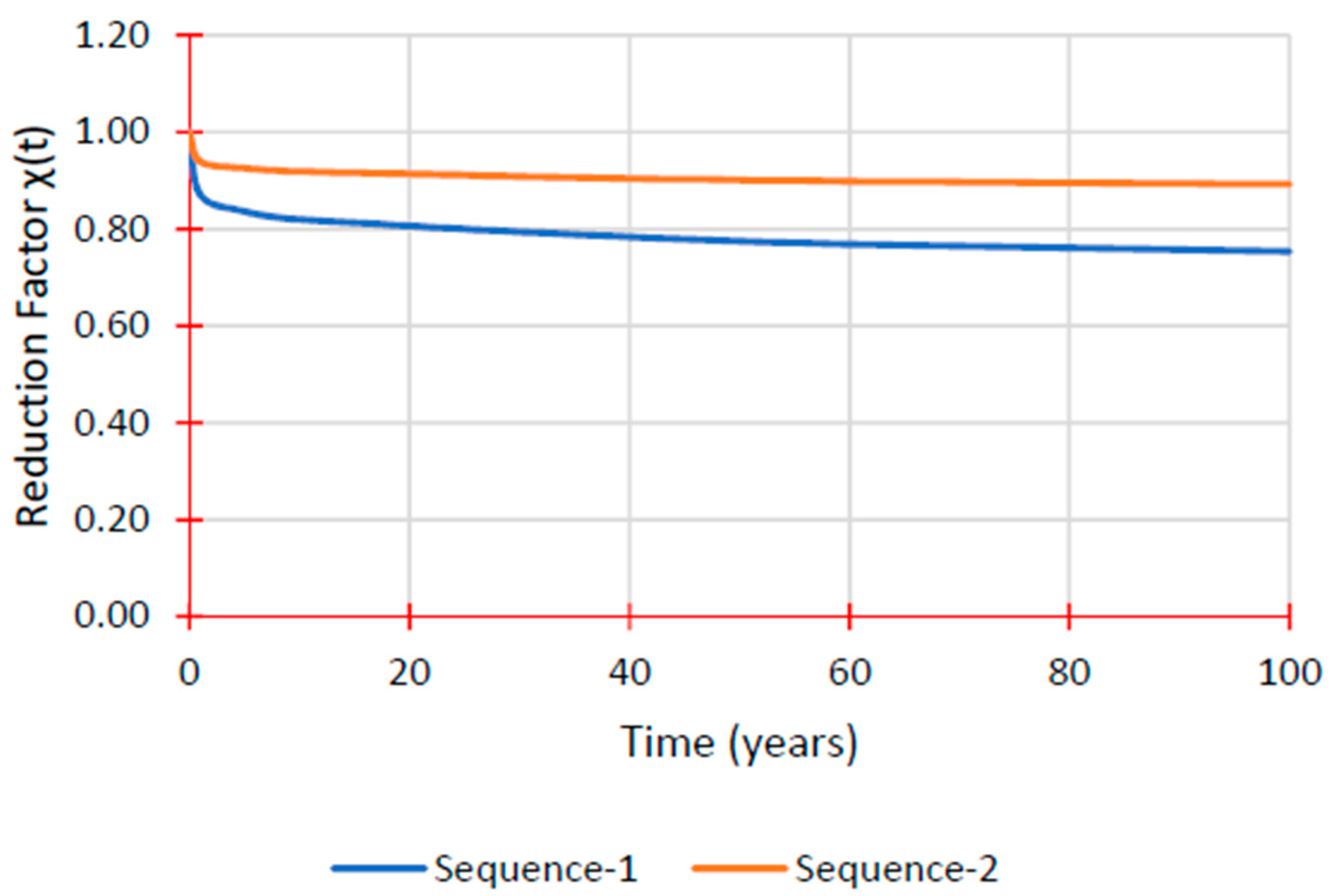
| Time (Years) | Sequence 1 | Sequence 2 | ||
|---|---|---|---|---|
| χ(t) | E(t) (MPa) | χ(t) | E(t) (MPa) | |
| 1 | 0.87 | 15,619.1 | 0.94 | 20,624.1 |
| 5 | 0.84 | 15,000.3 | 0.93 | 20,323.7 |
| 10 | 0.82 | 14,695.2 | 0.92 | 20,176.0 |
| 50 | 0.77 | 13,893.2 | 0.90 | 19,785.4 |
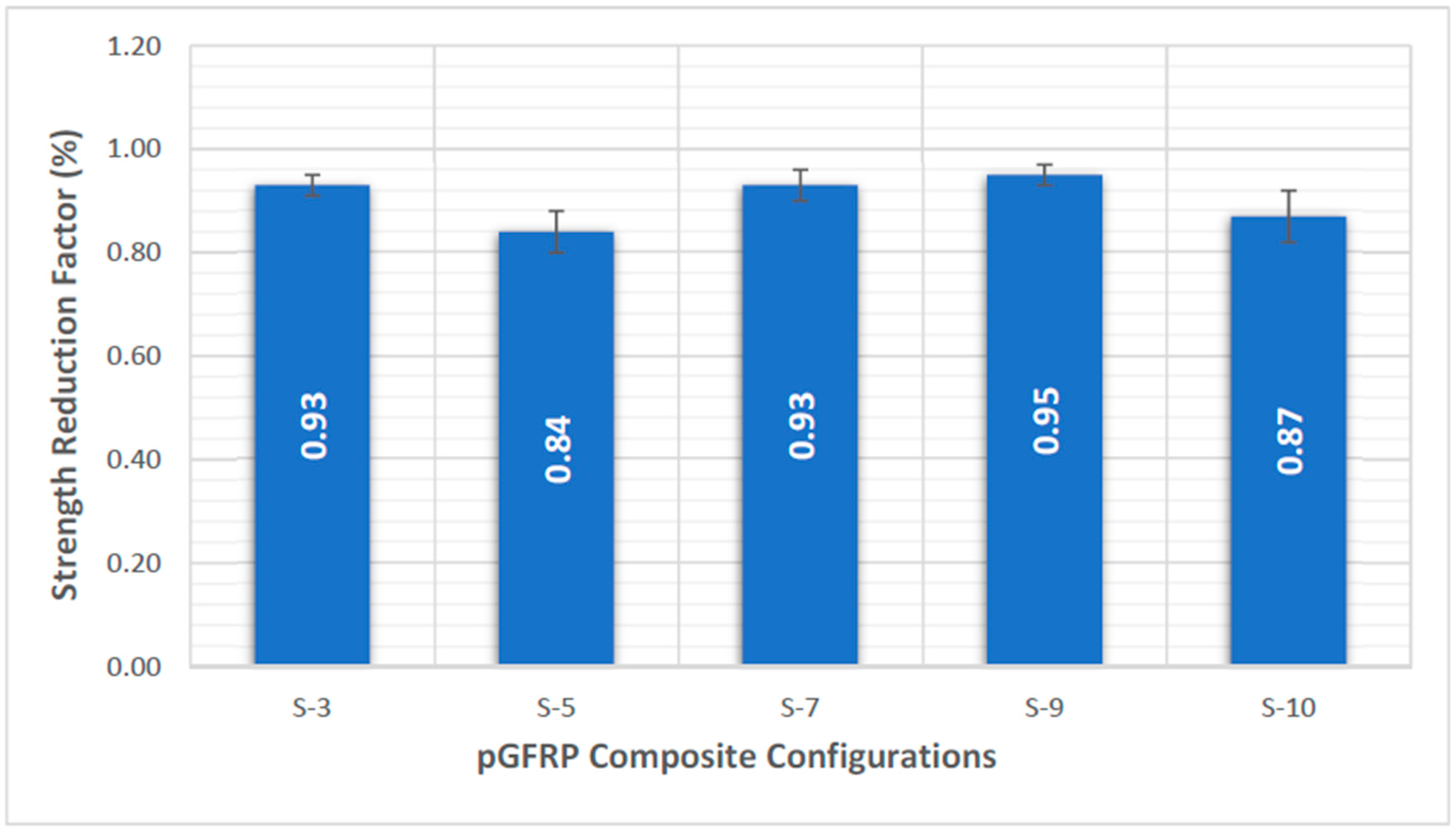
| No. | Configuration | Number of Layers | Layering Sequence |
|---|---|---|---|
| 1. | S-3 | 3 | 45°/0°/45° |
| 2. | S-5 | 5 | 45°/−45°/90°/0°/45° |
| 3. | S-7 | 7 | 45°/−45°/0°/90°/0°/90°/0° |
| 4. | S-9 | 9 | 0°/45°/0°/−45°/0°/−45°/0°/45°/0° |
| 5. | S-10 | 10 | 45°/−45°/0°/0°/0°/0°/0°/0°/−45°/45° |
| Material | Cross Arm Design | Main Arm | Experimental | Findley Model | Percentage Error (%) | Burger Model | Percentage Error (%) | Elastic Modulus, Ee (1010 Pa) | Viscoelastic Modulus, ηk (1014 Pa) | Refs |
|---|---|---|---|---|---|---|---|---|---|---|
| Wooden Cross Arm | Current | Right | 1.006 | 1.010 | 0.398 | 1.010 | 0.398 | 6.54 | 6.15 | |
| Left | 0.988 | 0.994 | 0.604 | 0.986 | 0.202 | 6.70 | 3.86 | [23] | ||
| Braced | Right | 0.806 | 0.798 | 0.993 | 0.806 | 0.000 | 8.20 | 5.37 | ||
| Left | 0.731 | 0.722 | 1.231 | 0.756 | 3.420 | 8.74 | 3.50 | |||
| Composite Cross Arm | Current | Right | 1.262 | 1.190 | 6.050 | 1.310 | 3.664 | 18.09 | 14.10 | |
| Left | 0.996 | 0.963 | 3.427 | 1.010 | 1.386 | 23.47 | 28.06 | [24] | ||
| Braced | Right | 0.990 | 0.987 | 0.304 | 0.993 | 0.304 | 23.87 | 192.10 | ||
| Left | 1.053 | 1.050 | 0.286 | 1.050 | 0.286 | 22.58 | 155.40 |
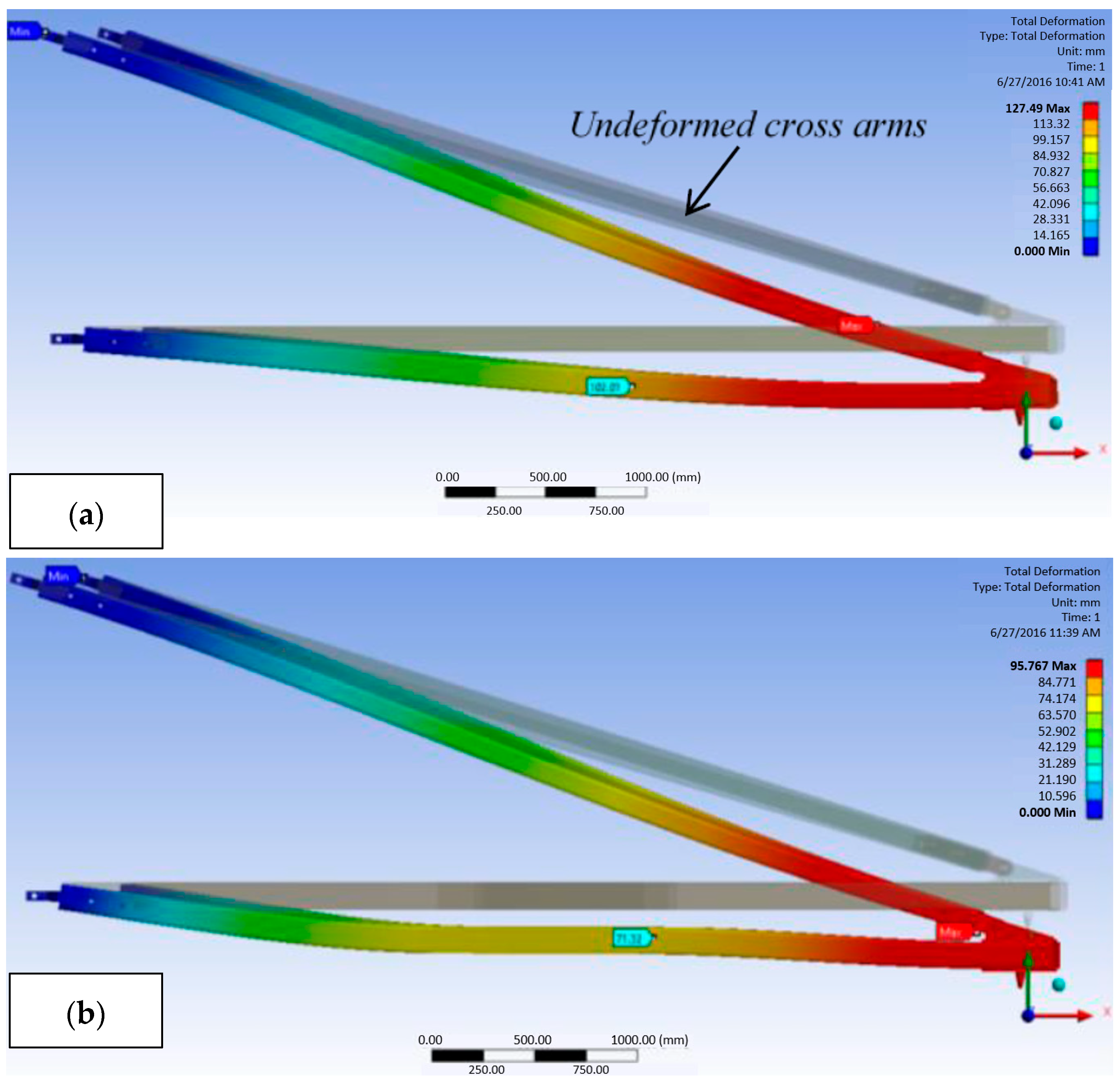
| Configuration | Mid-Span Deformation (Mm) | Peak Deformation (Mm) |
|---|---|---|
| Current design | 102.01 | 127.49 |
| Sleeve-enhanced design | 71.32 | 95.37 |
| Percentage reduction with sleeve installation | 30.09% | 25.19% |
Disclaimer/Publisher’s Note: The statements, opinions and data contained in all publications are solely those of the individual author(s) and contributor(s) and not of MDPI and/or the editor(s). MDPI and/or the editor(s) disclaim responsibility for any injury to people or property resulting from any ideas, methods, instructions or products referred to in the content. |
© 2023 by the authors. Licensee MDPI, Basel, Switzerland. This article is an open access article distributed under the terms and conditions of the Creative Commons Attribution (CC BY) license (https://creativecommons.org/licenses/by/4.0/).
Share and Cite
Asyraf, M.R.M.; Rafidah, M.; Madenci, E.; Özkılıç, Y.O.; Aksoylu, C.; Razman, M.R.; Ramli, Z.; Zakaria, S.Z.S.; Khan, T. Creep Properties and Analysis of Cross Arms’ Materials and Structures in Latticed Transmission Towers: Current Progress and Future Perspectives. Materials 2023, 16, 1747. https://doi.org/10.3390/ma16041747
Asyraf MRM, Rafidah M, Madenci E, Özkılıç YO, Aksoylu C, Razman MR, Ramli Z, Zakaria SZS, Khan T. Creep Properties and Analysis of Cross Arms’ Materials and Structures in Latticed Transmission Towers: Current Progress and Future Perspectives. Materials. 2023; 16(4):1747. https://doi.org/10.3390/ma16041747
Chicago/Turabian StyleAsyraf, Muhammad Rizal Muhammad, Mazlan Rafidah, Emrah Madenci, Yasin Onuralp Özkılıç, Ceyhun Aksoylu, Muhammad Rizal Razman, Zuliskandar Ramli, Sharifah Zarina Syed Zakaria, and Tabrej Khan. 2023. "Creep Properties and Analysis of Cross Arms’ Materials and Structures in Latticed Transmission Towers: Current Progress and Future Perspectives" Materials 16, no. 4: 1747. https://doi.org/10.3390/ma16041747