1. Introduction
Iron aluminide-based intermetallic alloys, due to their physicochemical and mechanical properties, as well as their stable structure and resistance to high-temperature corrosion, are promising materials for heat exchangers, nuclear reactor components, automotive exhaust systems, etc. [
1,
2,
3,
4,
5]. The main advantage of iron aluminides over heat-resistant nickel alloys and stainless steels is the availability and low cost of the base iron component, as well as their ease of processing.
Iron aluminides have found a wide practical application as protective coatings obtained by thermal spraying, especially HVOF, plasma (PS), and Arc and D-gun spraying [
2,
5,
6,
7,
8,
9,
10,
11]. Unlike in D-gun spraying [
10], during the PS process, powder particles falling into the high-temperature plasma jet (PJ) are melted and transferred to the substrate as droplets. In high-temperature flight, phenomena such as dispersion, coagulation, and changes in microstructure and phase composition occur in particles [
12,
13]. When the molten drop impacts the surface of the substrate, it spreads, solidifies, and forms a surface layer in the form of a splat. The structure and properties of coatings depend on the powder particles’ state during PS spraying. Completely molten particles contribute to the formation of dense layers and lead to reduced porosity. The degree of particle melting depends on the characteristics of the PJ (velocity and temperature, viscosity and thermal conductivity of the gas environment, degree of dissociation and ionisation of the gas molecules) and the material properties of the atomised particles (density, heat capacity, thermal conductivity, heat of fusion) [
14].
At present, one of the ways to obtain composite intermetallic powders of the Fe-Al system for thermal spraying is the mechanochemical synthesis method (MCS) [
15,
16,
17].
It should be noted, however, that unlike the D-gun process [
9,
10], the literature needs a comprehensive approach to studying the formation of plasma coatings using intermetallic powders of the Fe-Al system, including those obtained by the MCS method. Therefore, this study aimed to investigate the effect of changing the current intensity on the physicochemical processes occurring during forming Fe
3Al-based intermetallic coatings by plasma spraying.
2. Materials and Methods
Iron aluminide powders obtained by mechanochemical synthesis were used as research material, while iron, aluminium, aluminium alloy (Al5Mg), and Ti37.5Al intermetallic powders were applied as starting materials. Using Ti as an alloying element allows for realising several mechanisms of iron intermetallic strengthening, namely structure ordering, strengthening with dispersed inclusions, and the formation of coherent microstructures. Titanium differs by significant solubility in a solid state in Fe–Al phases that result in Fe
3Al structure stabilising around the FeAl structure at high temperatures. Strengthening with dispersed precipitations of hexagonal Laves phase (Fe, Al)
2Ti can take place in addition to strengthening due to structure ordering in the Fe–Al–Ti system. Furthermore, there is a specific range of composition in the Fe–Al–Ti system, where coherent structures [
18] are formed. If an element such as Mg is used for alloying powders based on the Fe
3Al intermetallic compound, it is possible to expect strengthening by incoherent compounds. Commercially available powders of the alloys Al5Mg and Ti37.5Al were used instead of the pure elements of aluminium, magnesium, and titanium to reduce the degree of oxidation of the MCS products.
The MCS process was performed in a planetary-type mill «Aktivator 2SL» for 5 h. The relation of the mass of balls to the mass of powder was 10:1. The central axis of the mill triboreactor was rotated at a 100 rpm rate; drums rotated around their axis at a 1500 rpm rate. Parts of the jar and milling agents were manufactured of 100Cr6 steel. The MCS process was performed in the air. Surface-active substances (SAS), namely oleic acid, were added to the mixture to prevent pickup of processed charge on the milling agents and jar wall, and to intensify the process of new synthesis phases.
The amount of aluminium alloy powder introduced in the mixture with iron powder was selected for formation in MCS of Fe3(Al, Mg) intermetallics in the case of AlMg that corresponded to 14 wt.% of Al-alloy and (Fe, Ti)3Al in the case of TiAl intermetallics. In the latter, the variant amount of introduced TiAl was 39.2 wt.%.
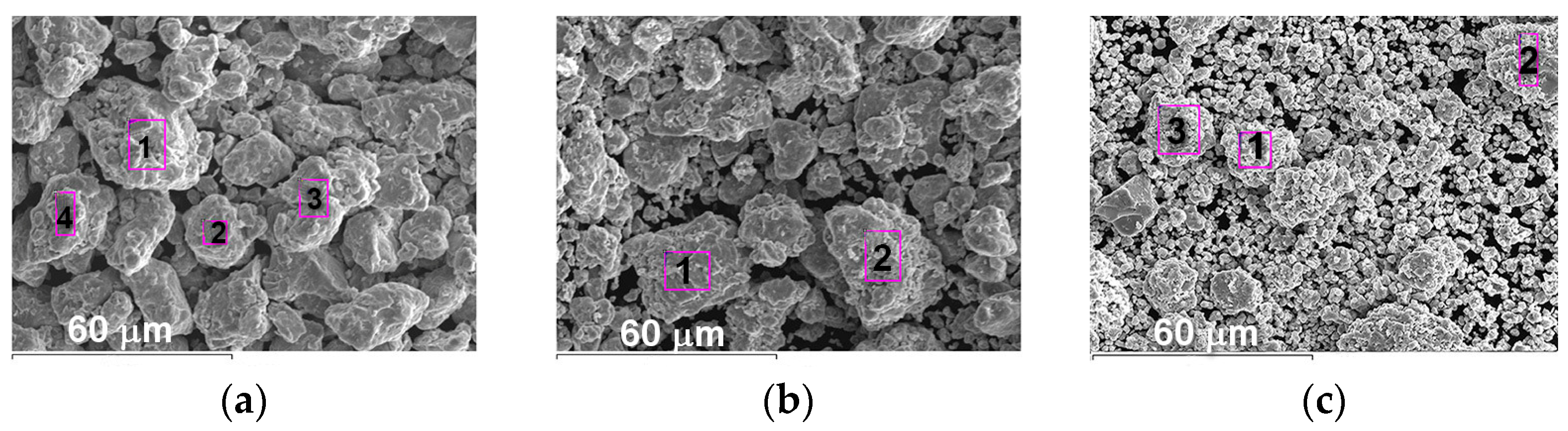
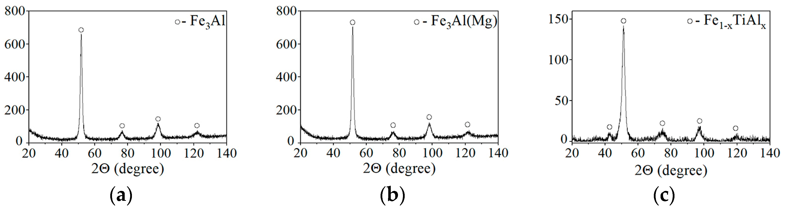
The microstructure, chemical, and phase composition of the MCS powder products (as an intermetallic compound based on Fe3Al iron aluminide) were confirmed, respectively, by SEM/EDS and XRD analysis using a JEOL 5310 microscope (Japan) operating at 20 kV, and a XRD Simens D-500 diffractometer (Germany) with CoKα radiation (λ= 0.178897 nm). An angular step size of 0.02°/min and a step time of 5 s per point were used, respectively.
The appearance and X-ray patterns of MCS powders of Fe
3Al, Fe-AlMg, and Fe-TiAl systems are shown in
Figure 1 and
Figure 2. The chemical composition of MCS powders is presented in
Table 1.
The characteristics of the MCS powders used in work for investigating the coating formation process during plasma spraying are shown in
Table 2 [
15,
16].
The crystallite size was estimated using the Scherrer equation:
where k is the Scherrer constant (≈0.94), λ is the wavelength of the radiation used (for Co λ = 1.78897 Ǻ), θ is the reflection angle, β is the true broadening of the X-ray line.
Based on the crystallite size calculations, it can be noted that the powders obtained by the MCS method are nanocrystalline.
The absence of fluidity in MCS products is related to the high specific surface area of the particles, and the challenge is to uniformly feed these powders into the stream during PS [
19]. To uniformly feed MCS products into PJ, they were conglomerated with a 5% polyvinyl alcohol solution in water, dried, and sifted for 40–80 µm particles.
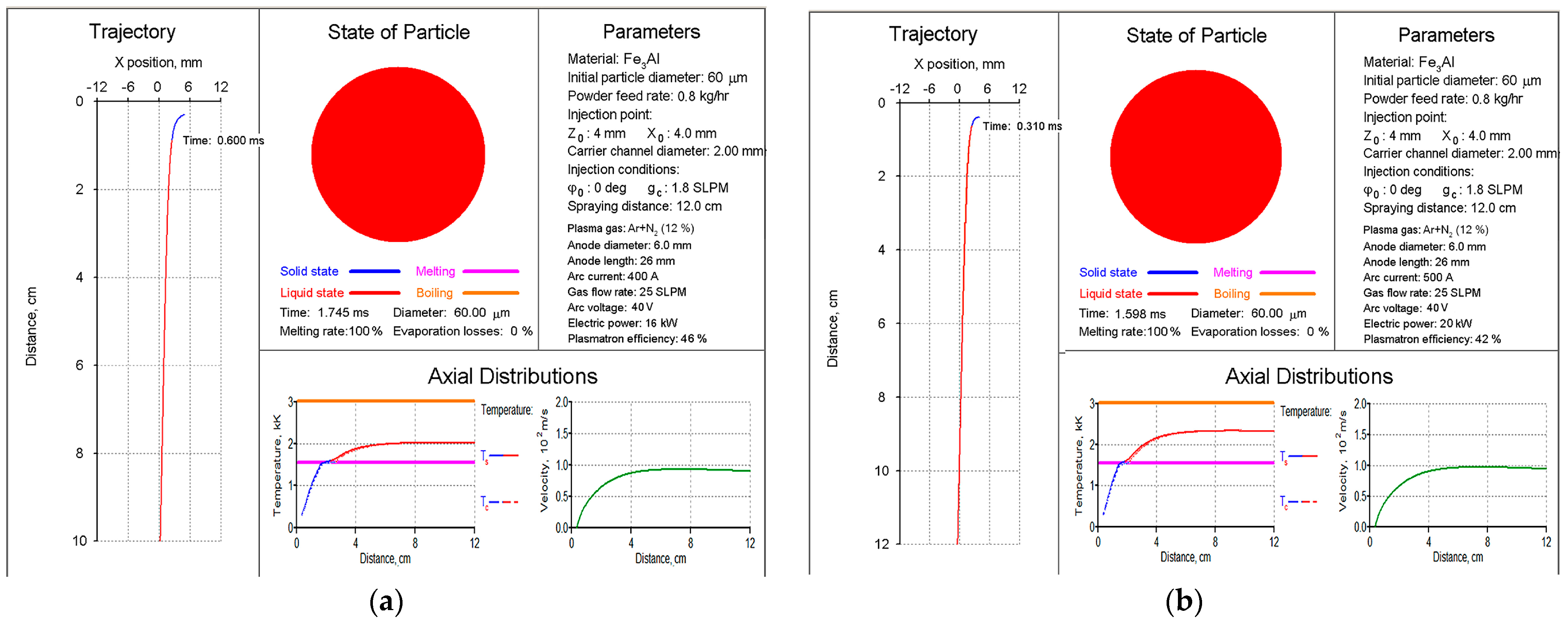
The choice of PS modes for Fe
3Al–based intermetallic materials was carried out using the CASPSP software version 3.1 [
20]. This software is designed for the computer simulation of turbulent plasma jets used in coating spraying and for modelling the heating and transport of atomised particles in such jets. Based on the analysis of the heating and transport of Fe
3Al particles in the range of 40–80 μm in PJ, it was found that, in terms of total melting and the lack of evaporation of the particles, the most reasonable parameters are a current of 400–500 A and a plasma gas (PG) Ar+N
2 flow rate of 25 SLPM (
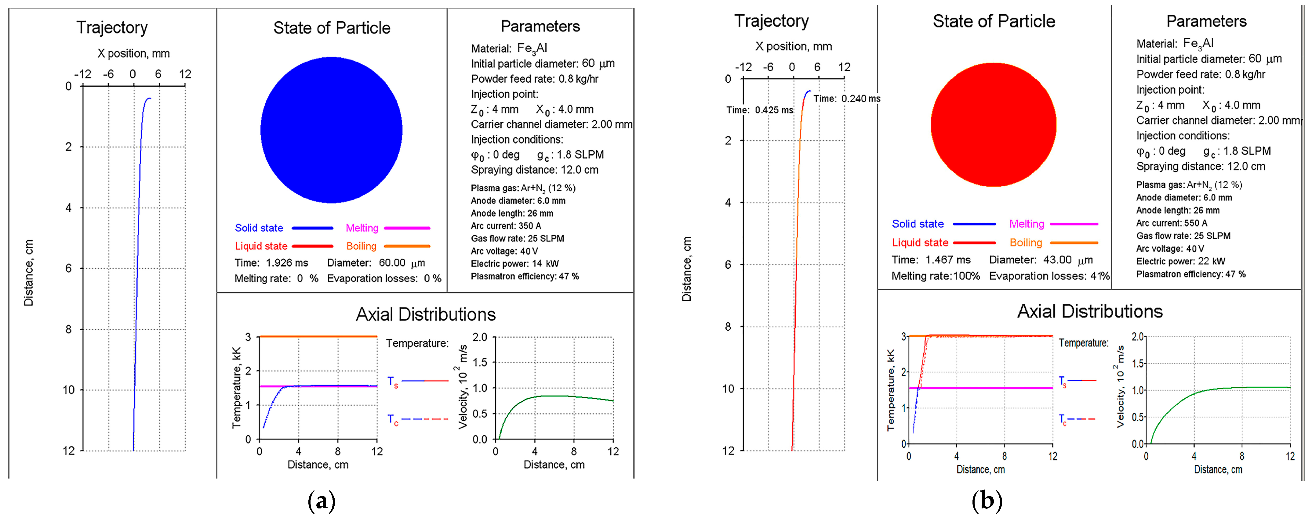
Figure 3). The use of other modes for spraying Fe
3Al-based powders is irrational due to the absence of the complete melting of particles at a current of less than 400 A (
Figure 4a) and the possibility of the material evaporation at a current of more than 500 A (
Figure 4b).
Powder spraying was carried out using the UPU–8M atmospheric plasma spraying device at different arc current (I) parameters. Changing the current significantly affects the temperature and velocity of PJ, which determines the heating and velocity of the particles during transport in the stream [
21]. The voltage, plasma gas (mixture Ar+N
2) flow rate, and powder feed rate were constant in all experiments. The Ar/N
2 ratio (7.3/1) and the flow rate of the plasma gas mixture (25 SLPM) made it possible to ensure the stable operation of the plasmatron at a voltage of 40 V. The modes of PS operation are presented in
Table 3.
Studies of the PS processes occurring in the powder during spraying were carried out by collecting particles transferred through the plasma jet into the water at a distance of 120 mm from the end of the plasma torch to the water’s surface. The analysis of the size and microstructure of the particles of sprayed powders collected in the water bath will determine the processes taking place with the powder particles in a plasma jet, on which the further formation of the coating structure depends.
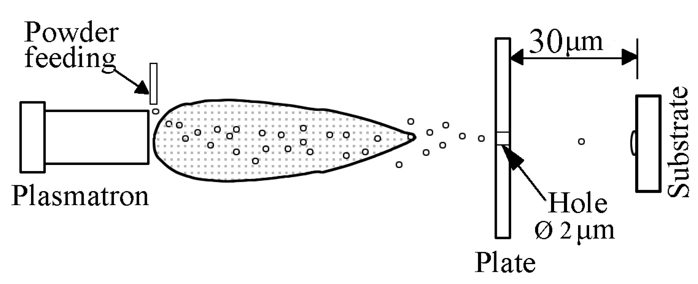
The state of the sprayed particle material after impact on the substrate was studied using the splat test. Spraying was carried out by moving polished stainless steel plates of 50 × 30 × 0.5 mm in a plane perpendicular to the jet axis (
Figure 5). As a result, single particles of sprayed material deformed upon contact with the substrate surface (splats) were fixed on the samples.
To investigate powders sprayed into the water and evaluate the degree of deformation of particles after their impact on the substrate, a complex technique was used, including the analysis of particle size distribution–ASOD-300 laser analyser (Novatek-Electro, Odesa, Ukraine); metallographic examinations–optical microscope “Neofot-32” with an attachment for digital photography; measurement of splats diameters (D) and classification of splats by appearance–optical microscope Jenavert; scanning electron microscopy (SEM)–scanning electron microscope JSM-6390LV (JEOL, Warsaw, Poland) with an attachment for energy dispersive analysis INCA in the secondary electron mode, in low vacuum (10–4 Pa), with an accelerating voltage of 20 kV.
Chemical etching of metallographic cross-sections was used to reveal the structure of powders sprayed into water. For Fe3Al and Fe-AlMg powders, a 10% alcoholic solution of nitric acid was used for 4–5 min; the Fe-TiAl powder was etched with a solution of HF+HCl+HNO3+water for 2–3 min. Etching was carried out for the powders sprayed in Mode 3.
The microhardness of the powders and coatings was determined in a microhardness tester PMT-3. To quantitatively analyse the content of pores in the coatings, an optical technique (image analysis method) was used, which consists of determining the area per detected pores relative to the entire area of the coating cross-section (ASTM E2109-01). Image-Pro Plus 7 software processed the digital image of the microstructure of the coatings.
3. Results and Discussion
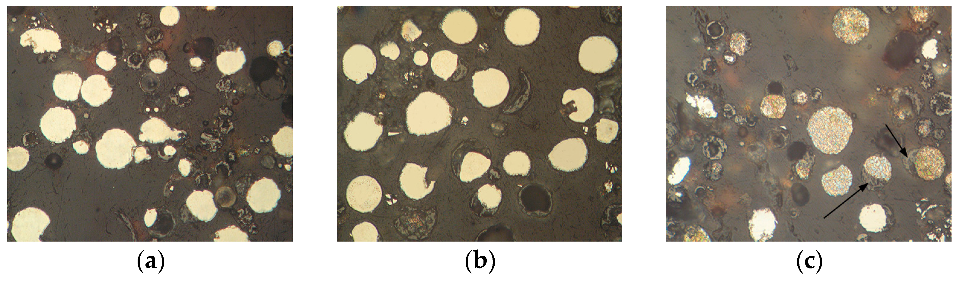
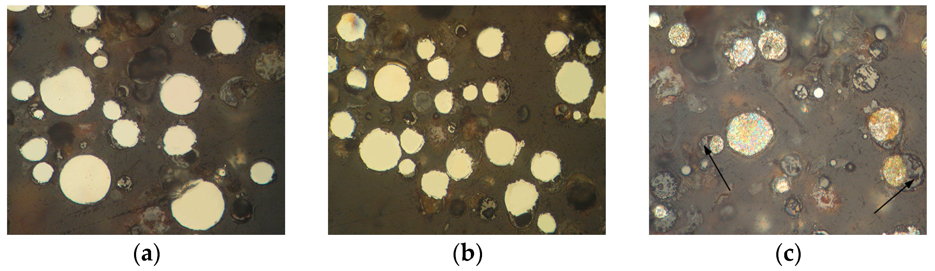
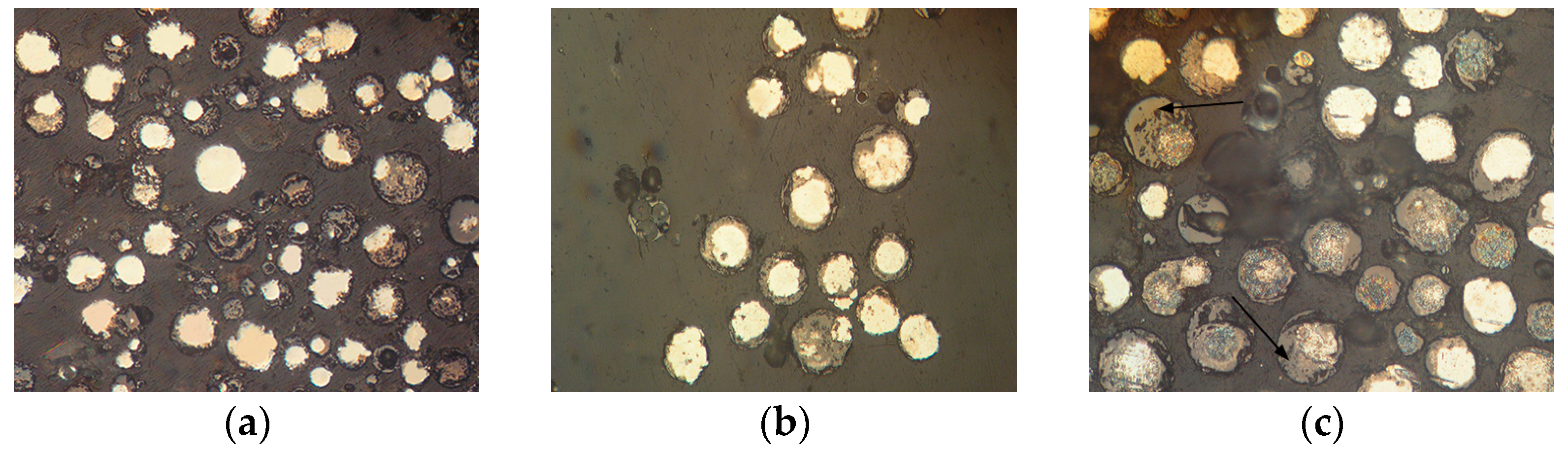
The appearance of powders of Fe
3Al, Fe-AlMg, and Fe-TiAl systems sprayed into the water at different currents is shown in
Figure 6,
Figure 7 and
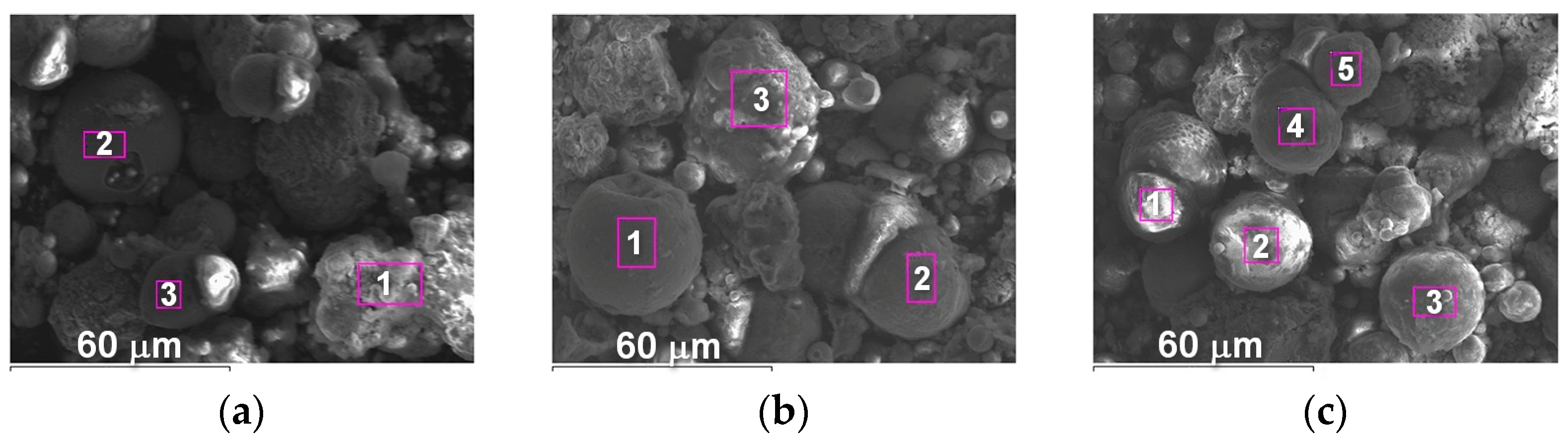
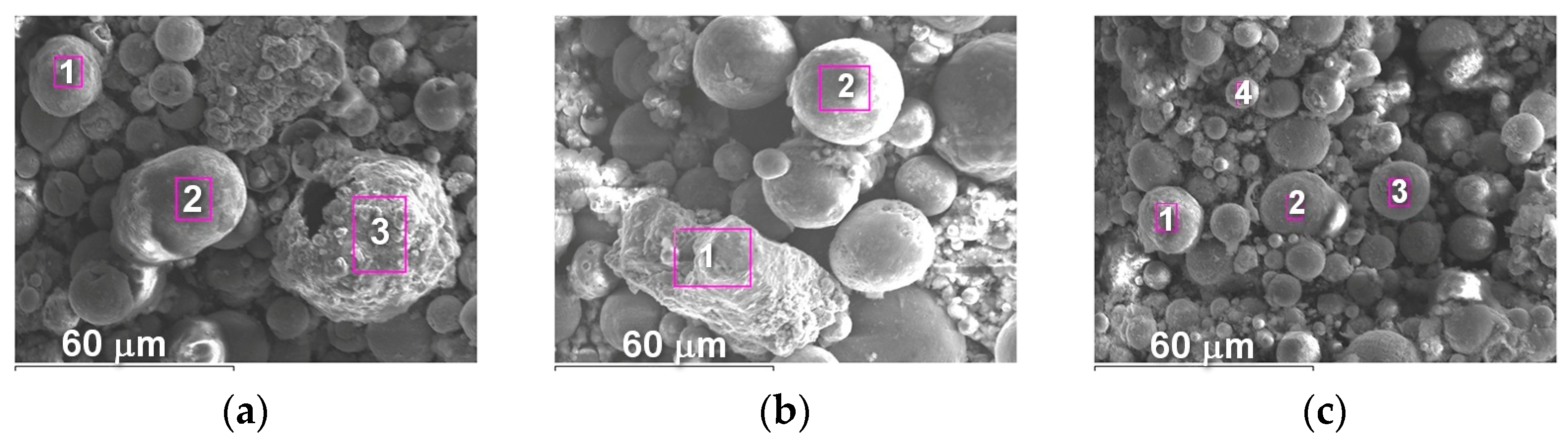
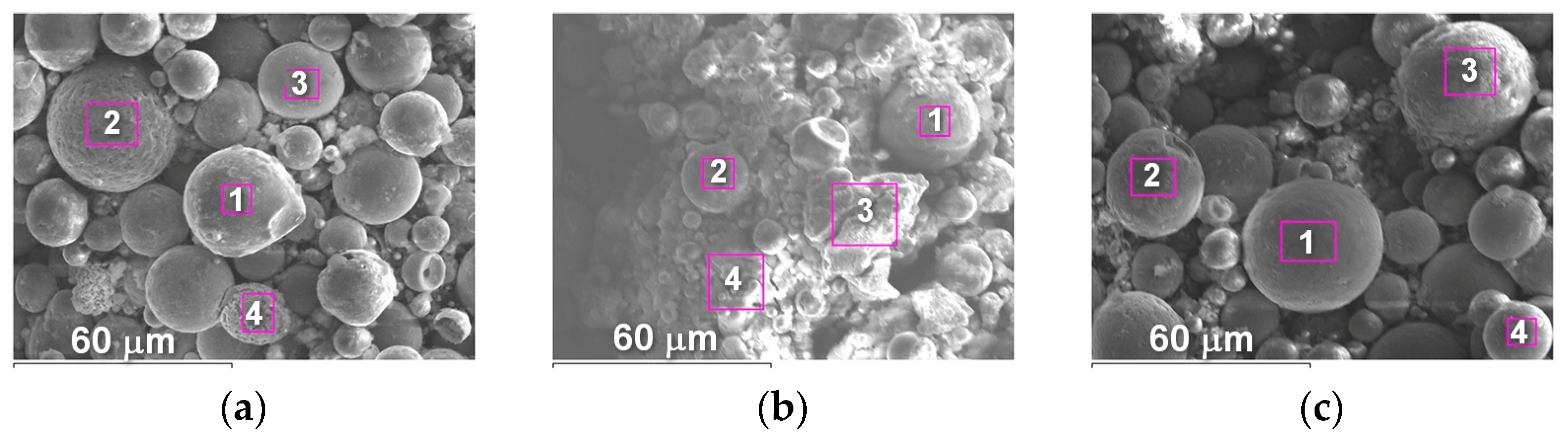
Figure 8. Analysis of the appearance of the powders showed that most of the particles (~95%) are spherical, indicating their complete melting during transferring through the plasma jet.
It is known [
22] that when a particle containing aluminium enters the oxygen-containing zones in a plasma stream, the process of aluminium oxidation develops with the appearance of an aluminium oxide film on the particle surface. By analysing the chemical composition of the powders, the presence of oxygen on the particle surfaces can be noted (
Table 4,
Table 5 and
Table 6), which indicates the formation of oxides (in particular, aluminium oxide–
Figure 6c,
Table 4, Spectrum 1;
Figure 7b,
Table 5, Spectrum 1).
The oxygen content in powders of the Fe-TiAl system is, on average, two times higher than the oxygen content in Fe3Al and Fe-AlMg powders. This is explained by the tendency of Ti and Al powder components to oxidize and their higher content in the initial powder mixtures. The reduced iron content in powders of the Fe-TiAl system also indicates the formation of an oxide film on the particle surface.
The microstructure of powders (
Figure 9,
Figure 10 and
Figure 11) shows that oxides on the surface of the particles are arranged in the form of thin films or obtain a domed shape as a result of the movement of particles in the turbulent plasma stream (indicated by arrows at
Figure 9,
Figure 10 and
Figure 11c).
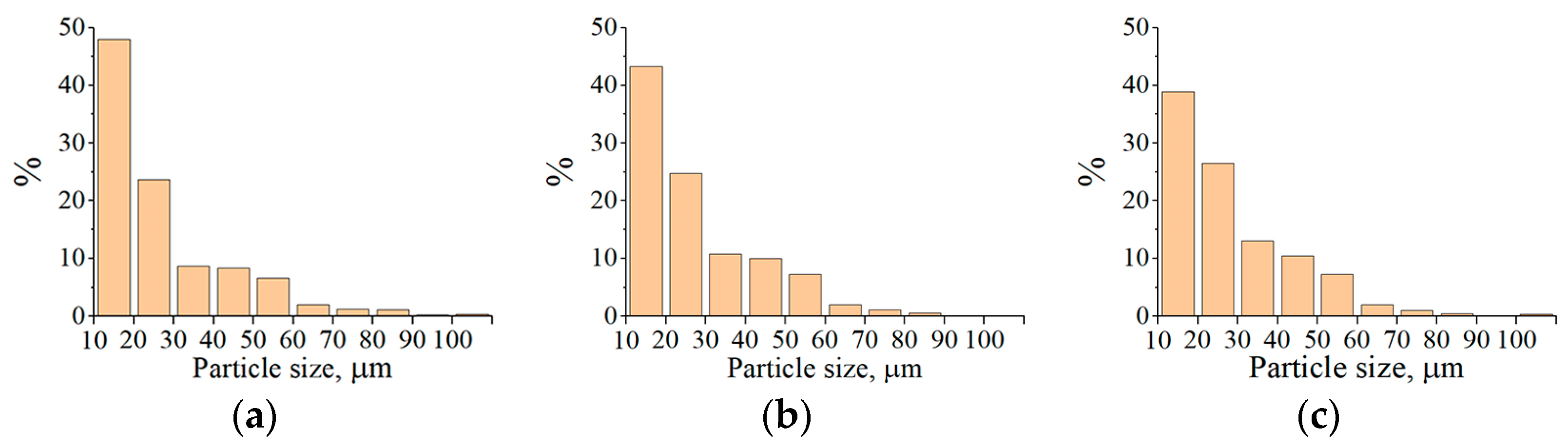
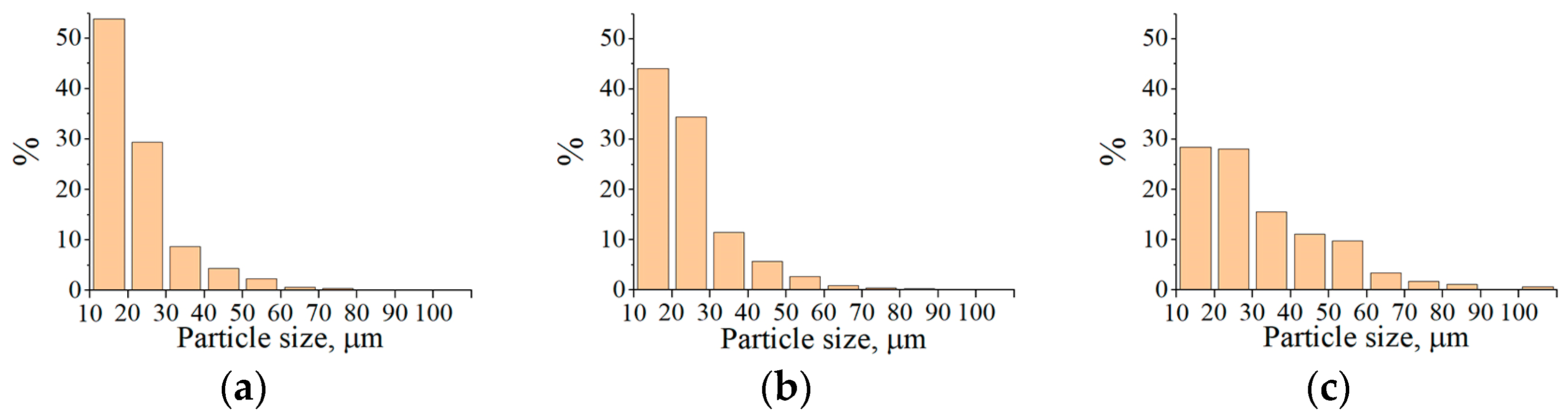
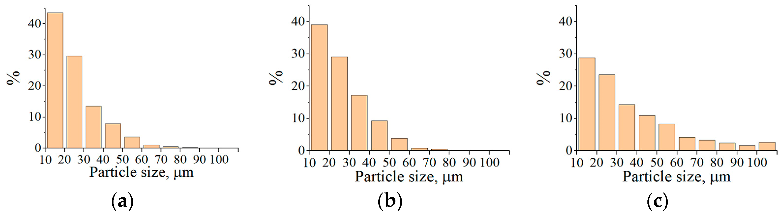
Histograms of the particle size distribution of Fe
3Al, Fe-AlMg, and Fe-TiAl powders after the conglomerates transferred through the plasma stream at different currents are shown in
Figure 12,
Figure 13 and
Figure 14. It can be seen that most of the powder particles (>55%) are in the size range of 10…30 µm. The reduction in particle size compared to the conglomerates fed into the plasma stream is related to the binder burnout during the interaction of the high-temperature plasma stream with the conglomerates.
MCS products also simultaneously fuse with the destruction of conglomerates in the plasma stream. As a result, the average particle size increases 2–3 times relative to the initial MCS products (
Table 7).
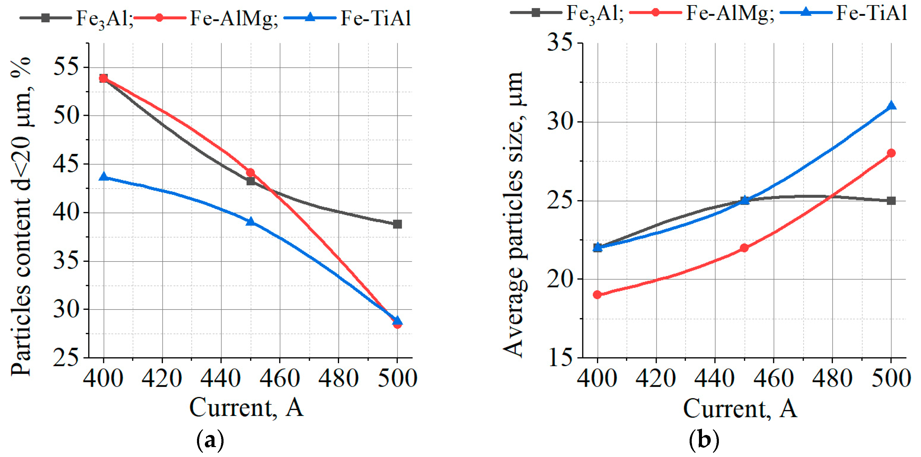
The increase in current leads to a 38–57% decrease in the number of particles within the size range of 10...20 μm and a 14–47% increase in the average particle size (
Figure 15). This may be due to the partial evaporation of small particles with increased heating.
Analysis of the shape of individual splats on substrates is one of the factors in optimizing plasma spraying methods. The degree of particle deformation D/d on impact with the sprayed surface determines the particle’s surface contact area. The larger deformed particle size D compared to the initial particle size d in the gas stream in front of the sprayed surface, the greater probability of strong adhesion of the contacting materials, with all other conditions being equal.
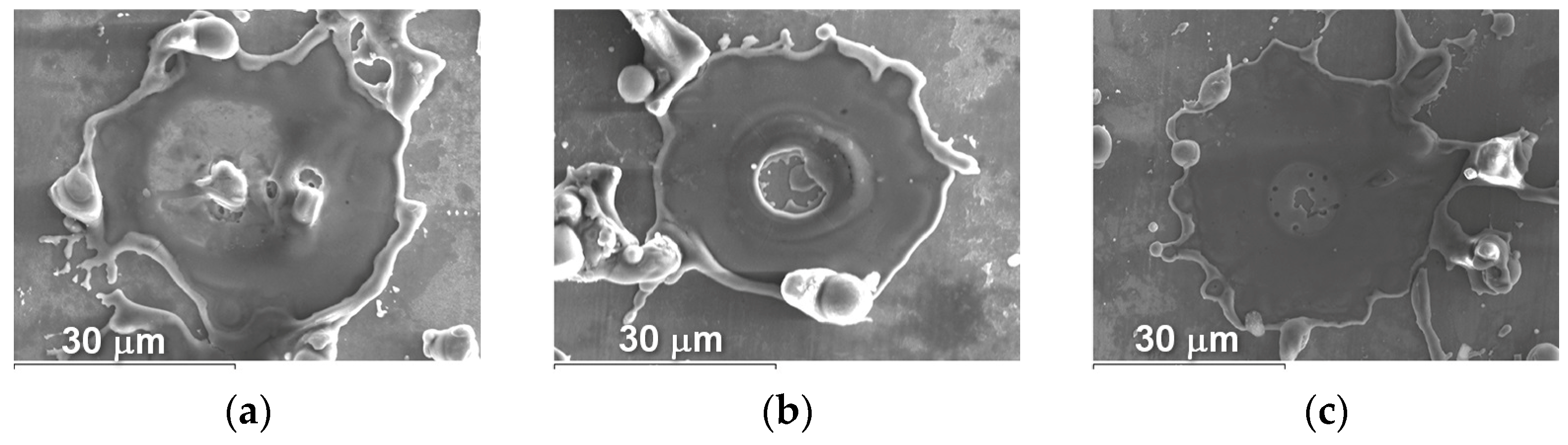
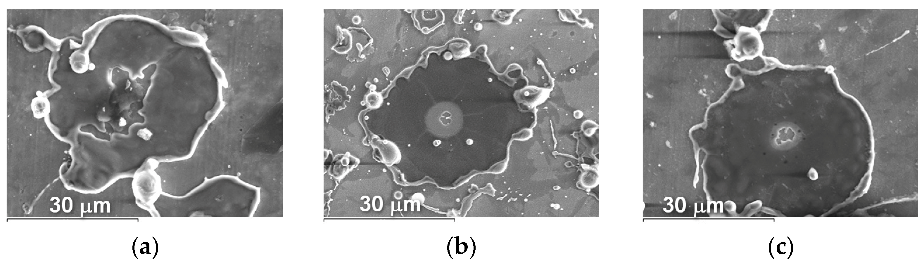
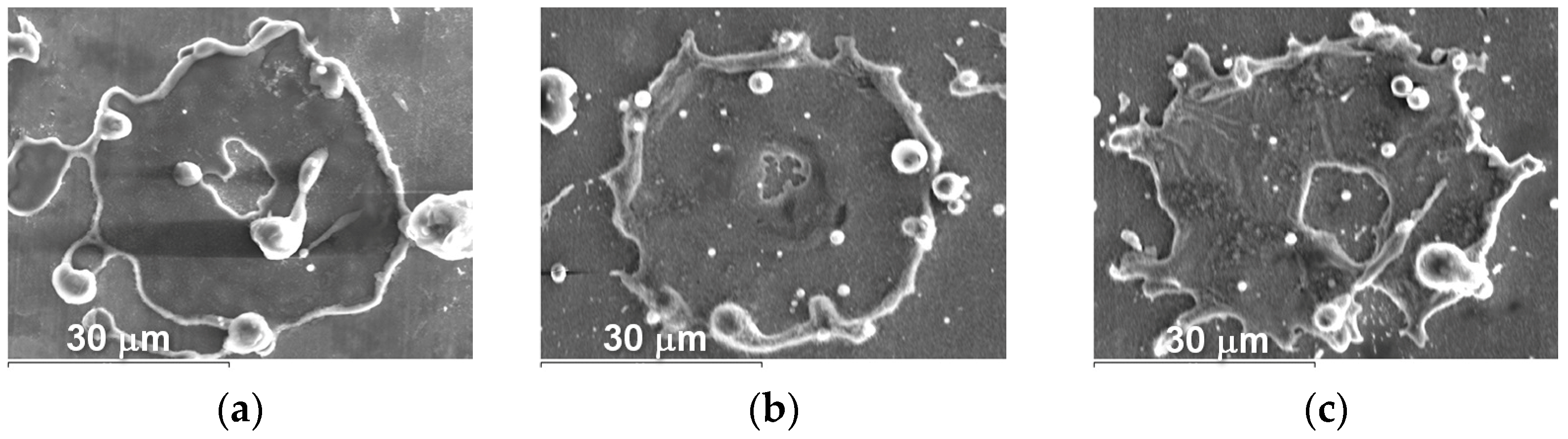
The appearance of splashes obtained by spraying Fe
3Al, Fe-AlMg, and Fe-TiAl powders as a function of current intensity is shown in
Figure 16,
Figure 17 and
Figure 18.
From the splats obtained during the interaction of powder particles with the substrate in all three modes, it can be concluded that the particles are in a fully molten state at the moment of impact with the substrate and have a disk shape. After the impact of the particles on the substrate and spread across the surface, the central part of the splats turns out to be unfilled by the material. This is explained by the fact that, inside the droplet, cavitation processes occur when it hits the surface of a solid; i.e., bubbles form and grow as the pressure drops to the saturation vapour pressure. The bubbles break through the liquid coating of the droplet and form crater-like holes in the deformed powder particle [
23].
The results of estimating the degree of deformation of D/d particles after impact on the ground are shown in
Table 8.
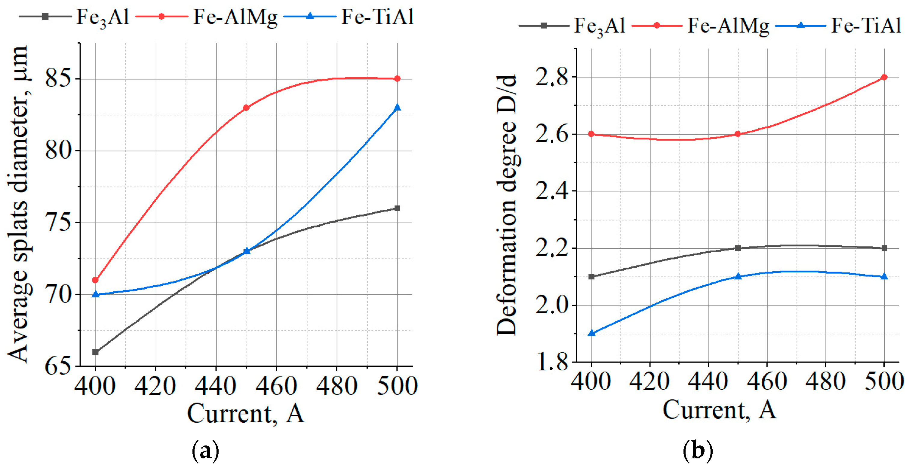
The dependence of the average splat diameter and the degree of particle deformation on the current is shown in
Figure 19. As can be seen, as the current increases, the average diameter of the splats and the degree of deformation of the particles also increase. This is due to the increase in the temperature and PJ velocity, which leads to a decrease in the surface tension and viscosity of the molten particle, and an increase in the impulse and pressure that act on the particle when it impacts the substrate.
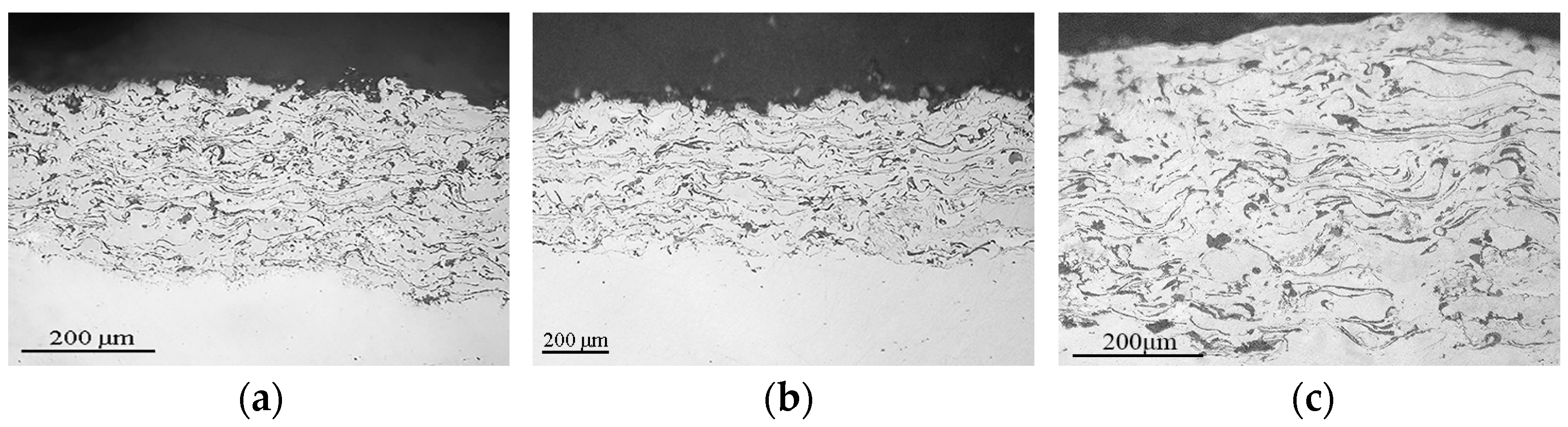
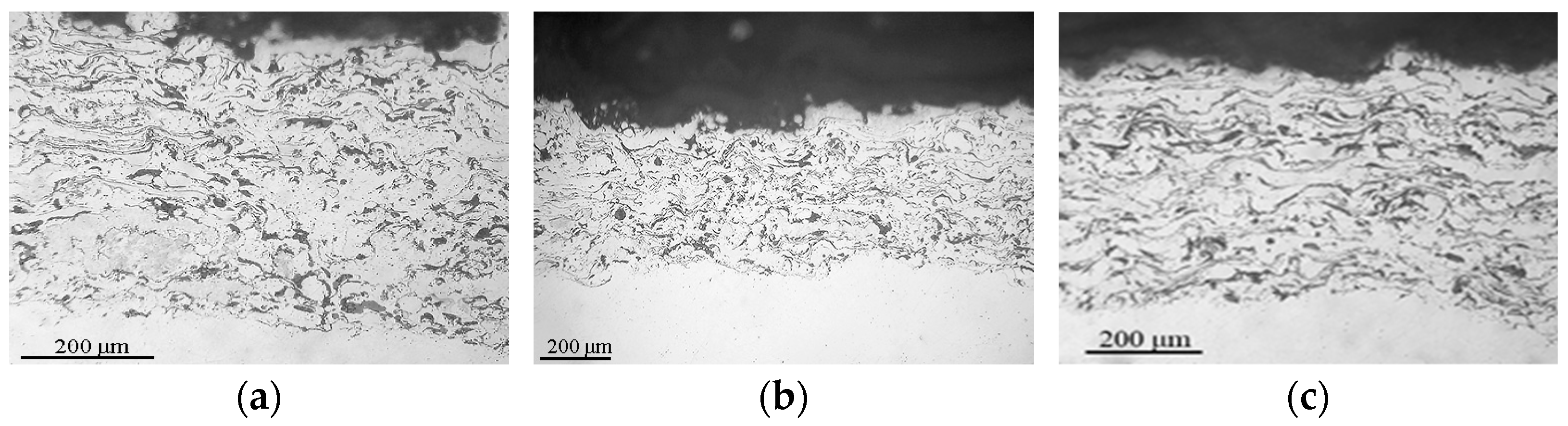
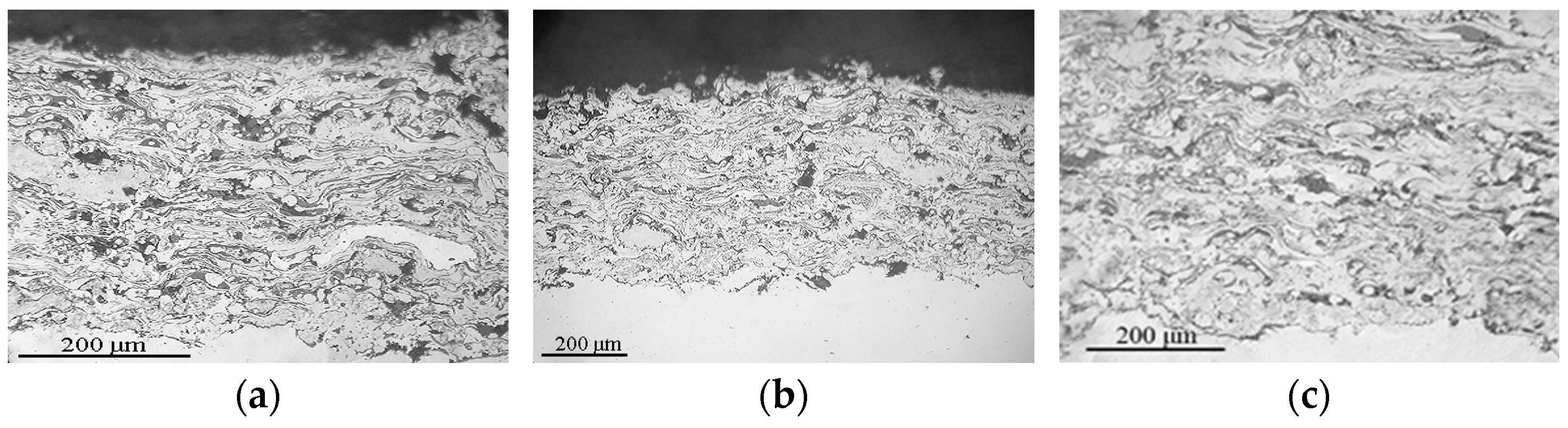
As a result of the plasma spraying of these powders, the coating layers are formed from completely melted and deformed particles, so the coatings have a dense thin-lamellar structure with a small number of oxide films at the lamella boundaries (
Figure 20,
Figure 21 and
Figure 22). The coatings have dense adherence to the steel substrate, and no delamination defects are observed.
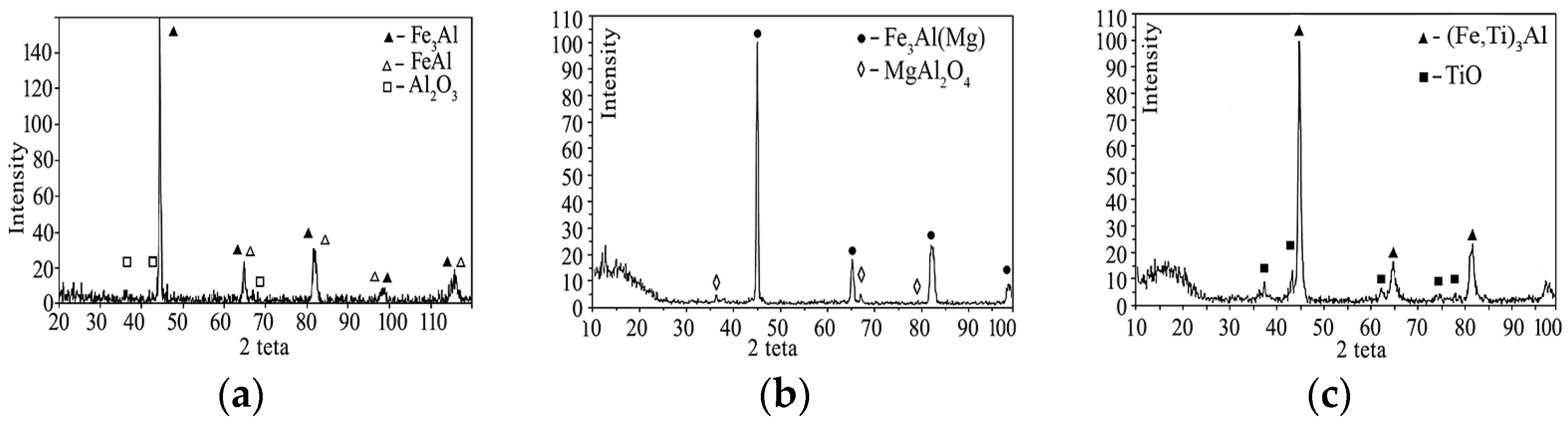
During the spraying of coatings of intermetallic powders, their phase composition does not completely coincide with the composition of the initial powders, which is associated with the active development of the process of particle oxidation during their flight. Oxides are present in all coatings. In the Fe
3Al coating, Al
2O
3 aluminium oxide is present; in the Fe-AlMg coating, complex oxide MgAl
2O
4 and in the Fe-TiAl coating, titanium oxide TiO are present (
Figure 23). In the Fe-AlMg coating, as in the original MCS powder, a solid solution of Mg in the Fe
3Al intermetallic compound is retained. In the Fe
3Al coating, the FeAl intermetallic phase is noted in addition to the base phase. During the spraying of the Fe-TiAl powder, the solid solution (Fe
1−xTiAl
x) was transformed into the intermetallic phase (Fe, Ti)
3Al.
Changes in the phase composition of the coatings do not occur when the spraying mode changes.
The characteristics of coatings obtained under different modes of plasma spraying are given in
Table 9.
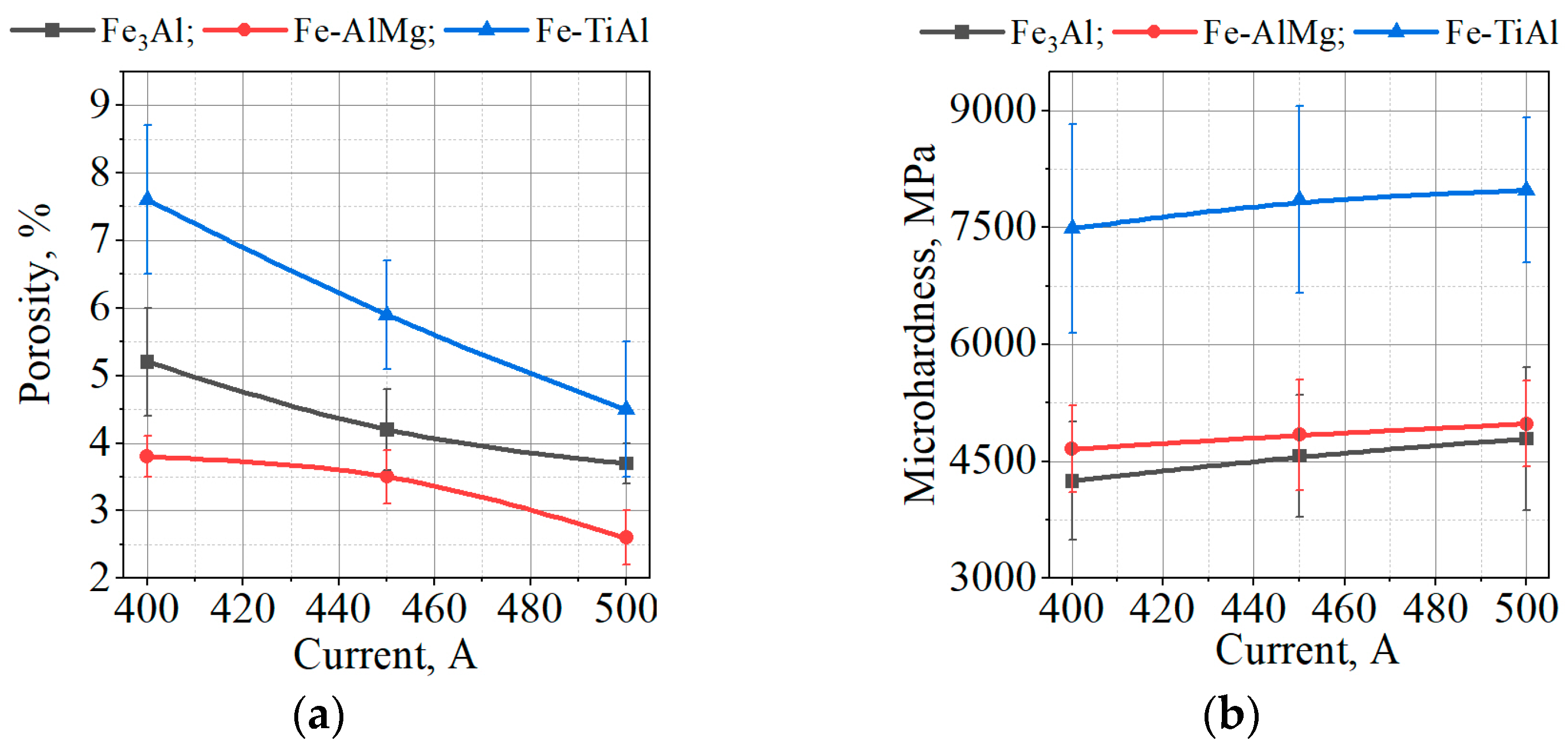
As expected, the porosity of the coatings decreases (on average by 2%) with an increase in current from 400 to 500 A (
Figure 24a), which is associated with a higher kinetic energy of particles upon impact with the substrate and a greater degree of their deformation with increasing current.
The results of measuring the microhardness of Fe3Al and Fe-AlMg coatings show a slight increase in microhardness relative to the initial MCS powders. This is most likely due to the formation of oxides in the coatings during spraying. In the case of sputtering of the Fe-TiAl powder, an increase in the microhardness of the coating relative to the microhardness of the initial MCS powder by ~2.3 times is noted. This is due to the formation of an intermetallic phase (Fe, Ti)3Al in the coating with additional hardening of the coating by the TiO oxide phase.
From
Figure 24b, the increasing current slightly increases the hardness values for all types of coatings related to the content of pores in the coatings. Increasing currents decrease the coatings’ porosity, which lead to an increase in microhardness values.
Thus, to obtain plasma coatings with a dense lamellar structure and high adhesion and cohesion strength from Fe3Al-based iron aluminide powders obtained by the MCS method, it is advisable to carry out the spraying process at the following spraying parameters: voltage of 40 V, current of 500 A, plasma–Ar/N2 gas mixture in the ratio of 7.3:1.

 ,
, 


