

Integrated Numerical Simulations and Experimental Measurements for the Sintering Process of Injection-Molded Ti-6Al-4V Alloy
 ,
,
Abstract
:1. Introduction
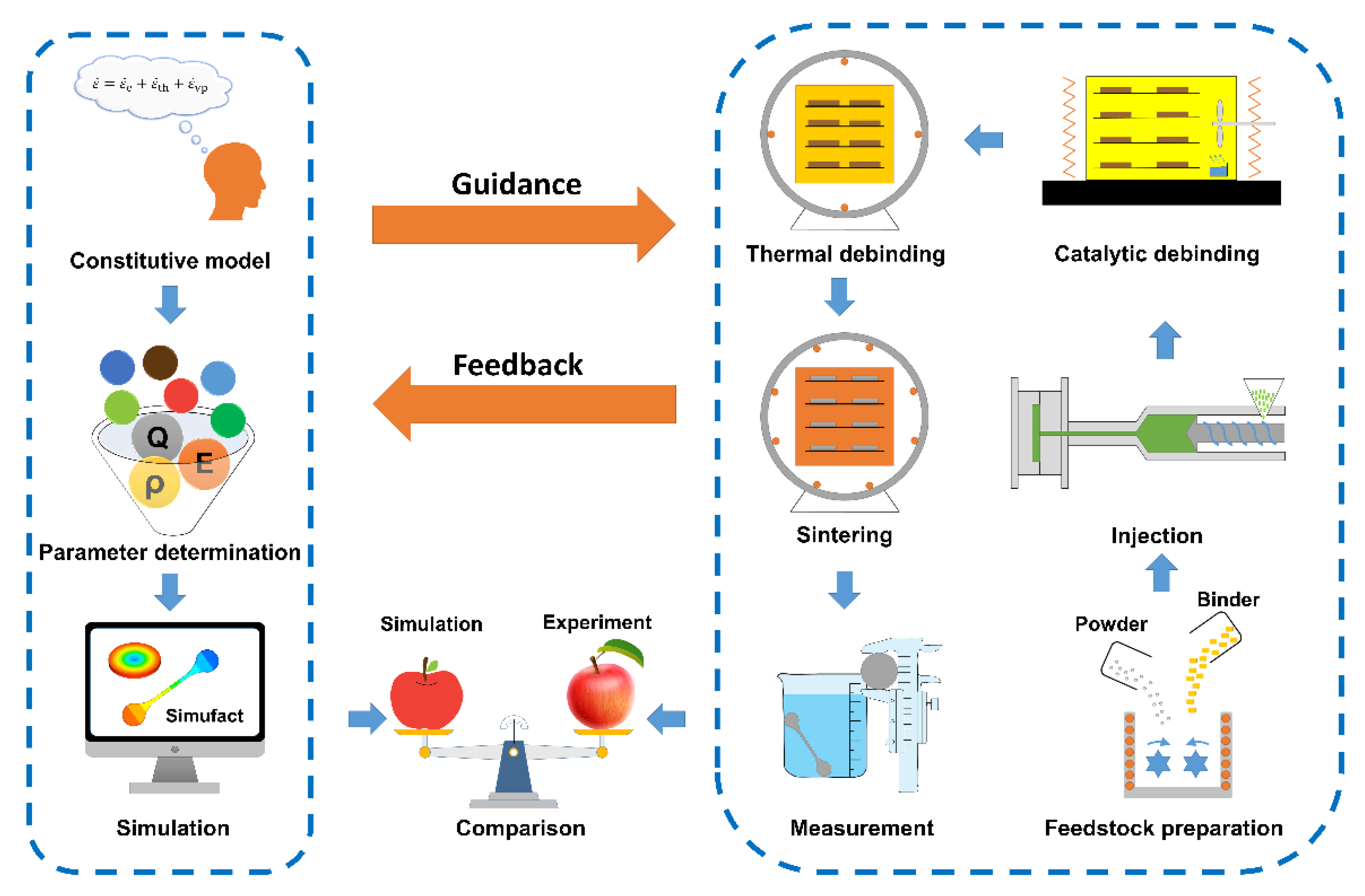
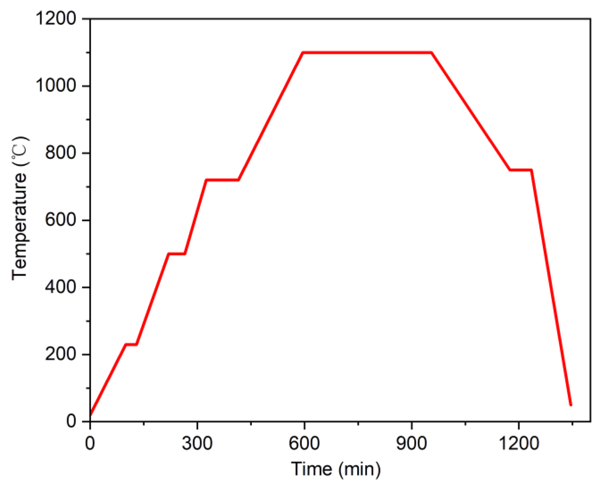
2. Methods
3. Constitutive Model of Sintering Process
3.1. Principle
3.2. Thermo-Elasto-Viscoplastic Constitutive Law
3.3. Steady Creep Law
3.4. Relative Density
3.5. Friction
4. Simulation
4.1. Parameter
4.2. Round Specimen Simulation
4.3. Elongated Specimen Simulation
5. Conclusions
Author Contributions
Funding
Institutional Review Board Statement
Informed Consent Statement
Data Availability Statement
Acknowledgments
Conflicts of Interest
References
- Tong, J.; Bowen, C.; Persson, J.; Plummer, A. Mechanical properties of titanium-based Ti-6Al-4V alloys manufactured by powder bed additive manufacture. Mater. Sci. Technol. 2016, 33, 138–148. [Google Scholar] [CrossRef] [Green Version]
- Moghadam, M.S.; Fayyaz, A.; Ardestani, M. Fabrication of titanium components by low-pressure powder injection moulding using hydride-dehydride titanium powder. Powder Technol. 2021, 377, 70–79. [Google Scholar] [CrossRef]
- Ghanmi, O.; Demers, V. Molding properties of titanium-based feedstock used in low-pressure powder injection molding. Powder Technol. 2021, 379, 515–525. [Google Scholar] [CrossRef]
- Suwanpreecha, C.; Alabort, E.; Tang, Y.B.; Panwisawas, C.; Reed, R.C.; Manonukul, A. A novel low-modulus titanium alloy for biomedical applications: A comparison between selective laser melting and metal injection moulding. Mater. Sci. Eng. A 2021, 812, 141081. [Google Scholar] [CrossRef]
- Sales, W.F.; Schoop, J.; Jawahir, I.S. Tribological behavior of PCD tools during superfinishing turning of the Ti6Al4V alloy using cryogenic, hybrid and flood as lubri-coolant environments. Tribol. Int. 2017, 114, 109–120. [Google Scholar] [CrossRef]
- Liang, X.L.; Liu, Z.Q. Tool wear behaviors and corresponding machined surface topography during high-speed machining of Ti-6Al-4V with fine grain tools. Tribol. Int. 2018, 121, 321–332. [Google Scholar] [CrossRef]
- Liang, X.L.; Liu, Z.Q.; Liu, W.T.; Wang, B.; Yao, G.H. Surface integrity analysis for high-pressure jet assisted machined Ti-6Al-4V considering cooling pressures and injection positions. J. Manuf. Process. 2019, 40, 149–159. [Google Scholar] [CrossRef]
- Dehghan-Manshadi, A.; Bermingham, M.J.; Dargusch, M.S.; StJohn, D.H.; Qian, M. Metal injection moulding of titanium and titanium alloys: Challenges and recent development. Powder Technol. 2017, 319, 289–301. [Google Scholar] [CrossRef] [Green Version]
- Xu, P.; Pyczak, F.; Limberg, W.; Willumeit-Römer, R.; Ebel, T. Superior fatigue endurance exempt from high processing cleanliness of metal-injection-molded β Ti-Nb-Zr for bio-tolerant applications. Mater. Des. 2021, 211, 110141. [Google Scholar] [CrossRef]
- Mahmud, N.N.; Azam, F.‘A.A.; Ramli, M.I.; Foudzi, F.M.; Ameyama, K.; Sulong, A.B. Rheological properties of irregular-shaped titanium-hydroxyapatite bimodal powder composite moulded by powder injection moulding. J. Mater. Res. Technol. 2021, 11, 2255–2264. [Google Scholar] [CrossRef]
- Hamidi, M.F.F.A.; Harun, W.S.W.; Samykano, M.; Ghani, S.A.C.; Ghazalli, Z.; Ahmad, F.; Sulong, A.B. A review of biocompatible metal injection moulding process parameters for biomedical applications. Mater. Sci. Eng. C 2017, 78, 1263–1276. [Google Scholar] [CrossRef] [PubMed] [Green Version]
- Bootchai, S.; Taweejun, N.; Manonukul, A.; Kanchanomai, C. Metal injection molded titanium: Mechanical properties of debinded powder and sintered metal. J. Mater. Eng. Perform. 2020, 29, 4559–4568. [Google Scholar] [CrossRef]
- Subaşıa, M.; Safarianb, A.; Karataş, Ç. An investigation on characteristics and rheological behaviour of titanium injection moulding feedstocks with thermoplastic-based binders. Powder Metall. 2019, 62, 229–239. [Google Scholar] [CrossRef]
- Subaşi, M.; Safarian, A.; Karataş, Ç. The investigation of production parameters of Ti-6Al-4V component by powder injection molding. Int. J. Adv. Manuf. Technol. 2019, 105, 4747–4760. [Google Scholar] [CrossRef]
- Meng, J.H.; Loh, N.H.; Fu, G.; Tay, B.Y.; Tor, S.B. Micro powder injection moulding of alumina micro-channel part. J. Eur. Ceram. Soc. 2011, 31, 1049–1056. [Google Scholar] [CrossRef]
- Kwon, Y.S.; Wu, Y.X.; Suri, P.; German, R.M. Simulation of the sintering densification and shrinkage behavior of powder-injection-molded 17-4 PH stainless steel. Metall. Mater. Trans. A 2004, 35, 257–263. [Google Scholar] [CrossRef]
- Kong, X.; Quinard, C.; Barriere, T.; Gelin, J.C. Micro powder injection moulding of 316L stainless steel feedstock and numerical simulation of the sintering stage. In Proceedings of the 10th International Conference on Numerical Methods in Industrial Forming Processes, Pohang, Republic of Korea, 13–17 June 2010. [Google Scholar]
- Mohsin, I.U.; Lager, D.; Hohenauer, W.; Gierl, C.; Danninger, H. Finite element sintering analysis of metal injection molded copper brown body using thermo-physical data and kinetics. Comput. Mater. Sci. 2012, 53, 6–11. [Google Scholar] [CrossRef]
- German, R.M. Thermodynamics of sintering. In Sintering of Advanced Materials, 1st ed.; Fang, Z.Z., Ed.; Woodhead Publishing: Sawston, UK, 2010; Volume 1, pp. 3–32. [Google Scholar]
- Choi, J.-P.; Lee, G.-Y.; Song, J.-I.; Lee, W.-S.; Lee, J.-S. Sintering behavior of 316L stainless steel micro-nanopowder compact fabricated by powder injection molding. Powder Technol. 2015, 279, 196–202. [Google Scholar] [CrossRef]
- Sahli, M.; Djoudi, H.; Gelin, J.C.; Barriere, T.; Assoul, M. Numerical simulation and experimental analysis of the sintered micro-parts using the powder injection molding process. Microsyst. Technol. 2018, 24, 1495–1508. [Google Scholar] [CrossRef]
- Mamen, B. Experimental Investigation and Numerical Simulation of Thermal Debinding and Sintering Processes in Powder Injection Moulding. Ph.D. Thesis, University of Franche-Comté, Besançon, France, 2013. [Google Scholar]
- Węglewski, W.; Basista, M.; Chmielewski, M.; Pietrzak, K. Modelling of thermally induced damage in the processing of Cr-Al2O3 composites. Compos. Part B-Eng. 2012, 43, 255–264. [Google Scholar] [CrossRef]
- Braginsky, M.; Tikare, V.; Olevsky, E. Numerical simulation of solid state sintering. Int. J. Solids Struct. 2005, 42, 621–636. [Google Scholar] [CrossRef]
- Oyama, K. Diplas, S.; M’hamdi, M.; Gunnæs, A.E.; Azar, A.S. Heat source management in wire-arc additive manufacturing process for Al-Mg and Al-Si alloys. Addit. Manuf. 2019, 26, 180–192. [Google Scholar]
- Kang, T.G.; Ahn, S.; Chung, S.H.; Chung, S.T.; Kwon, Y.S.; Park, S.J.; German, R.M. Modeling and simulation of metal injection molding (MIM). In Handbook of Metal Injection Molding, 2nd ed.; Heaney, D.F., Ed.; Woodhead Publishing: Sawston, UK, 2019; Volume 2, pp. 219–252. [Google Scholar]
- Martin, S.; Guessasma, M.; Léchelle, J.; Fortin, J.; Saleh, K.; Adenot, F. Simulation of sintering using a Non Smooth Discrete Element Method. Application to the study of rearrangement. Comput. Mater. Sci. 2014, 84, 31–39. [Google Scholar] [CrossRef]
- Song, J.; Barriere, T.; Liu, B.; Gelin, J.C. Numerical simulation of sintering process in ceramic powder injection moulded components. In Proceedings of the 9th International Conference on Numerical Methods in Industrial Forming Processes, Porto, Portugal, 17–21 June 2007. [Google Scholar]
- Behrensa, B.-A.; Chugreeva, A.; Chugreev, A. FE-simulation of hot forging with an integrated heat treatment with the objective of residual stress prediction. In Proceedings of the 21st International ESAFORM Conference on Material Forming, Palermo, Italy, 23–25 April 2018. [Google Scholar]
- Bauer, A.; Manurung, Y.H.P.; Sprungk, J.; Graf, M.; Awiszus, B.; Prajadhiana, K. Investigation on forming–welding process chain for DC04 tube manufacturing using experiment and FEM simulation. Int. J. Adv. Manuf. Technol. 2019, 102, 2399–2408. [Google Scholar] [CrossRef]
- Nosewicz, S.; Rojek, J.; Pietrzak, K.; Chmielewski, M. Viscoelastic discrete element model of powder sintering. Powder Technol. 2013, 246, 157–168. [Google Scholar] [CrossRef]
- Jeong, M.-S.; Yoo, J.-H.; Rhim, S.-H.; Lee, S.-K.; Oh, S.-I. A unified model for compaction and sintering behavior of powder processing. Finite Elem. Anal. Des. 2012, 53, 56–62. [Google Scholar] [CrossRef]
- Pagáč, M.; Hajnyš, J.; Halama, R.; Aldabash, T.; Měsíček, J.; Jancar, L.; Jansa, J. Prediction of model distortion by FEM in 3D printing via the selective laser melting of stainless steel AISI 316L. Appl. Sci. 2021, 11, 1656. [Google Scholar] [CrossRef]
- Shi, J.; Cheng, Z.; Barriere, T.; Liu, B.; Gelin, J.C. Multiphysic coupling and full cycle simulation of microwave sintering applied to a ceramic compact obtained by ceramic injection moulding. Powder Metall. 2017, 60, 404–414. [Google Scholar] [CrossRef]
- Song, J.; Gelin, J.C.; Barriere, T.; Liu, B. Experiments and numerical modelling of solid state sintering for 316L stainless steel components. J. Mater. Process. Technol. 2006, 177, 352–355. [Google Scholar] [CrossRef]
- Sahli, M.; Lebied, A.; Gelin, J.C.; Barriere, T.; Necib, B. Numerical simulation and experimental analysis of solid-state sintering response of 316 L stainless steel micro-parts manufactured by metal injection molding. Int. J. Adv. Manuf. Technol. 2015, 79, 2079–2092. [Google Scholar] [CrossRef] [Green Version]
- Aryanpour, G.; Mashl, S.; Warke, V. Elastoplastic–viscoplastic modelling of metal powder compaction: Application to hot isostatic pressing. Powder Metall. 2013, 56, 14–23. [Google Scholar] [CrossRef]
- Gu, Y.; Zeng, F.H.; Qi, Y.L.; Xia, C.Q.; Xiong, X. Tensile creep behavior of heat-treated TC11 titanium alloy at 450–550 °C. Mater. Sci. Eng. A 2013, 575, 74–85. [Google Scholar] [CrossRef]
- Villa, M. Metallurgical and Mechanical Modelling of Ti-6Al-4V for Welding Applications. Ph.D. Thesis, University of Birmingham, Birmingham, UK, 2016. [Google Scholar]
- Sahli, M.; Gelin, J.C.; Barriere, T. Simulation and modelling of sintering process for 316L stainless steel metal injection molding parts. Adv. Mater. Process. Technol. 2015, 1, 577–585. [Google Scholar] [CrossRef]


| Menu | Parameter | Value | Unit |
|---|---|---|---|
| General properties | Gravitational acceleration | 9.8 | m/s2 |
| Initial relative density | 60.1 | % | |
| Friction coefficient | 0.3 | - | |
| Pre-exponential constant | 2.36 × 10−36 | 1/(Pa·s) | |
| Creep activation energy | 277 | kJ/mol | |
| Gas constant | 8.31 | J/(mol·K) | |
| Thermal properties | Specific heat capacity | 540 | J/(kg·K) |
| Melting temperature | 1640 | °C | |
| Latent heat for melting | 419 | J/g | |
| Thermal expansion coefficient | 8.84 × 10⁻⁶ | 1/K | |
| Mechanical properties | Ultimate strain | 12 | % |
| Stress exponent | 5.64 | - | |
| Poisson’s ratio | 0.34 | - | |
| Yield strength | 941 | MPa | |
| Tensile strength | 1000 | MPa |
| Parameter | Before Sintering | Experiment after Sintering | Simulation after Sintering | Error |
|---|---|---|---|---|
| Diameter (mm) | 34.80 | 29.78 | 29.90 | 0.4% |
| Thickness (mm) | 2.91 | 2.48 | 2.49 | 0.4% |
| Relative density (%) | 60.10 | 97.80 | 95.26 | −2.6% |
Publisher’s Note: MDPI stays neutral with regard to jurisdictional claims in published maps and institutional affiliations. |
© 2022 by the authors. Licensee MDPI, Basel, Switzerland. This article is an open access article distributed under the terms and conditions of the Creative Commons Attribution (CC BY) license (https://creativecommons.org/licenses/by/4.0/).
Share and Cite
Su, S.; Hong, Z.; Huang, Y.; Wang, P.; Li, X.; Wu, J.; Wu, Y. Integrated Numerical Simulations and Experimental Measurements for the Sintering Process of Injection-Molded Ti-6Al-4V Alloy. Materials 2022, 15, 8109. https://doi.org/10.3390/ma15228109
Su S, Hong Z, Huang Y, Wang P, Li X, Wu J, Wu Y. Integrated Numerical Simulations and Experimental Measurements for the Sintering Process of Injection-Molded Ti-6Al-4V Alloy. Materials. 2022; 15(22):8109. https://doi.org/10.3390/ma15228109
Chicago/Turabian StyleSu, Shaohua, Zijian Hong, Yuhui Huang, Peng Wang, Xiaobao Li, Junwen Wu, and Yongjun Wu. 2022. "Integrated Numerical Simulations and Experimental Measurements for the Sintering Process of Injection-Molded Ti-6Al-4V Alloy" Materials 15, no. 22: 8109. https://doi.org/10.3390/ma15228109