
The Joining of Copper to Stainless Steel by Solid-State Welding Processes: A Review

 , ,
, ,  , ,
, ,
Abstract
:1. Introduction—Joining of Copper to Stainless Steel Bimetallic System
2. Solid-State Welding of Copper/Stainless Steel Bimetallic Joint
2.1. Hot Isostatic Pressing of Copper/Stainless Steel Bimetallic Joint
2.2. Diffusion Bonding for Copper/Stainless Steel Bimetallic Joint
2.3. Explosive Welding for Copper/Stainless Steel Bimetallic Joint
2.4. Friction Welding for Copper/Stainless Steel Bimetallic Joint
2.5. Friction Stir Welding for Copper/Stainless Steel Bimetallic Joint
2.6. Another Solid-State Welding for Copper/Stainless Steel Bimetallic Joint
3. Conclusions and Future Work
- Despite obtaining strong weld joints, both DB and HIP face limitation due to part geometry, longer joint formation time, repetitive heating and cooling cycles, and heavy equipment involvement. However, the DB is cost-effective compared to those of HIP. While DB further increases the quantity and length of material diffusion (copper and stainless steel), the electric current application improves in tensile properties. However, work needs to be done to identify the interlayer material and its thickness while adopting DB and HIP processes to synthesize the dissimilar joints of Cu/SS.
- The ratio of explosive material weight to flyer plate weight and standoff distance are key parameters during EW of Cu/SS. The mechanical properties of the joint increase with the increase in the above-mentioned factors. The microstructural heterogeneity and the extent of diffusion across the joint interface are considered as limitations. The joint interface experiences plastic deformation due to impact energy. The heterogeneity across the length of the joint and within the molten pocket are the main challenges, along with the risk involved in the explosion. Furthermore, diversified dissimilar joint geometries must be explored to increase the application of EW process to join Cu/SS system.
- The thin layer of intermetallic compounds along the interface during FSW of Cu/SS, present due to limited diffusion compared to DB and HIP, is the essential characteristic of FSW. The tool pin offset on either side of the joint line is the critical factor in deciding the soundness of the Cu/SS joint in FSW. However, offsetting towards the copper side is recommended. The effects of tool pin geometry and shoulder features are not explored during FSW of Cu/SS. Thermal assistance under FSW decreases the load on tool and enhances the joint’s plastic deformation; however, future researchers must establish optimal heat assistance and methods. The material transport mechanism in correlation with the tool interaction with both copper and stainless-steel base materials is of great interest to obtain better joint properties and higher tool life during the FSW of a Cu/SS bimetallic system. While tensile testing, the strain rate has a significant effect on the strength of the joints; hence, strength of the dissimilar joints has to be compared in relation with strain rate of the test.
- In general, EW, FSW, and UW processes were less explored to join the Cu/SS bimetallic system compared to DB and HIP.
- Understanding the effect of the geometries (form factor) on the deformation behaviour of both copper and SS are essential to find the optimal operating window for effective and efficient joints of Cu/SS during DB, EW, FSW, HIP, and UW processing routes; hence, a thorough study is targeted on this aspect.
Author Contributions
Funding
Institutional Review Board Statement
Informed Consent Statement
Data Availability Statement
Acknowledgments
Conflicts of Interest
References
- Paul, H.; Chulist, R.; Mania, I. Structural Properties of Interfacial Layers in Tantalum to Stainless Steel Clad with Copper Interlayer Produced by Explosive Welding. Metals 2020, 10, 969. [Google Scholar] [CrossRef]
- Lavrishchev, A.V.; Prokopev, S.V.; Tynchenko, V.S.; Myrugin, A.V.; Kukartsev, V.V.; Bashmur, K.A.; Sergienko, R.B.; Tynchenko, V.V.; Lysyannikov, A.V. Investigation of the Solid-Phase Joint of VT-14 Titanium Alloy with 12KH18N10T Stainless Steel Obtained by Diffusion Welding through Intermediate Layers. Metals 2021, 11, 1325. [Google Scholar] [CrossRef]
- Gu, X.; Cui, Z.; Gu, X.; Shao, J. Wire-Feeding Laser Welding of Copper/Stainless Steel Using Different Filler Metals. Materials 2021, 14, 2122. [Google Scholar] [CrossRef] [PubMed]
- Carvalho, G.H.S.F.L.; Galvão, I.; Mendes, R.; Leal, R.M.; Loureiro, A. Aluminum-to-Steel Cladding by Explosive Welding. Metals 2020, 10, 1062. [Google Scholar] [CrossRef]
- Ahmed, M.M.Z.; Ataya, S.; Seleman, M.M.E.-S.; Allam, T.; Alsaleh, N.A.; Ahmed, E. Grain Structure, Crystallographic Texture, and Hardening Behavior of Dissimilar Friction Stir Welded AA5083-O and AA5754-H14. Metals 2021, 11, 181. [Google Scholar] [CrossRef]
- Jairaja, R.; Naik, G.N. Fabrication of Single and Dual Adhesive Bonded Lap Joints Between Dissimilar Composite Adherends. In Industry 4.0 and Advanced Manufacturing; Chakrabarti, A., Arora, M., Eds.; Springer: Singapore, 2021; pp. 185–195. [Google Scholar]
- Kobayashi, T.; Shohji, I. Fabrication of Three-Dimensional Microstructure Film by Ni-Cu Alloy Electrodeposition for Joining Dissimilar Materials. Mater. Sci. Forum 2021, 1016, 738–743. [Google Scholar] [CrossRef]
- Jambhale, S.; Kumar, S.; Kumar, S. Characterization and Optimization of Flat Friction Stir Spot Welding of Triple Sheet Dissimilar Aluminium Alloy Joints. Silicon 2021, 14, 815–830. [Google Scholar] [CrossRef]
- Beygi, R.; Zarezadeh Mehrizi, M.; Akhavan-Safar, A.; Safaei, S.; Loureiro, A.; da Silva, L.F.M. Design of Friction Stir Welding for Butt Joining of Aluminum to Steel of Dissimilar Thickness: Heat Treatment and Fracture Behavior. Int. J. Adv. Manuf. Technol. 2021, 112, 1951–1964. [Google Scholar] [CrossRef]
- Norwood, D.S.; Schneberger, B.M.; Fuller, K.M.; Brown, K. Prediction of Airframe Thermal Stresses for Hybrid Composite-Metallic Structure. In AIAA Scitech 2021 Forum; AIAA SciTech Forum; American Institute of Aeronautics and Astronautics: Reston, Virginia, 2021. [Google Scholar] [CrossRef]
- Huang, J.; Zeng, J.; Bai, Y.; Cheng, Z.; Wang, Y.; Zhao, Q.; Liang, D. Effect of Adhesive Layer Properties on the Shear Strength of Single-Lap Structures of Dissimilar Materials Based on the Cohesive Zone Model. J. Mech. Sci. Technol. 2021, 35, 133–143. [Google Scholar] [CrossRef]
- Zhou, H.; Lee, J.; Kang, M.; Kim, H.; Lee, H.; In, J. Bin. All Laser-Based Fabrication of Microchannel Heat Sink. Mater. Des. 2022, 221, 110968. [Google Scholar] [CrossRef]
- Guo, Z.; Pan, Y.; Guo, R.; Fang, Z. Fabrication of Fullerene Decorated by Iron Compound and Its Effect on the Thermal Stability and Flammability for High-Density Polyethylene. Fire Mater. 2020, 44, 506–515. [Google Scholar] [CrossRef]
- Wang, D.; Liu, L.; Deng, G.; Deng, C.; Bai, Y.; Yang, Y.; Wu, W.; Chen, J.; Liu, Y.; Wang, Y.; et al. Recent Progress on Additive Manufacturing of Multi-Material Structures with Laser Powder Bed Fusion. Virtual Phys. Prototyp. 2022, 17, 329–365. [Google Scholar] [CrossRef]
- Rodrigues, T.A.; Bairrão, N.; Farias, F.W.C.; Shamsolhodaei, A.; Shen, J.; Zhou, N.; Maawad, E.; Schell, N.; Santos, T.G.; Oliveira, J.P. Steel-Copper Functionally Graded Material Produced by Twin-Wire and Arc Additive Manufacturing (T-WAAM). Mater. Des. 2022, 213, 110270. [Google Scholar] [CrossRef]
- Selema, A.; Ibrahim, M.N.; Sergeant, P. Metal Additive Manufacturing for Electrical Machines: Technology Review and Latest Advancements. Energies 2022, 15, 1076. [Google Scholar] [CrossRef]
- Sadeghian, A.; Iqbal, N. A Review on Dissimilar Laser Welding of Steel-Copper, Steel-Aluminum, Aluminum-Copper, and Steel-Nickel for Electric Vehicle Battery Manufacturing. Opt. Laser Technol. 2022, 146, 107595. [Google Scholar] [CrossRef]
- Vyas, H.; Mehta, K.P. Effect of Multi Pass Friction Stir Processing on Surface Modification and Properties of Aluminum Alloy 6061. Key Eng. Mater. 2019, 813, 404–410. [Google Scholar] [CrossRef]
- Pravin Tamil Selvan, C.; Kalaiselvan, K.; Dinaharan, I.; Palanivel, R. Assessment of Microstructure and Tensile Behavior of Hot Wire Gas Tungsten Arc Welded Pure Nickel Tubes. Trans. Indian Inst. Met. 2021, 74, 355–368. [Google Scholar] [CrossRef]
- Furuya, H.S.; Yabu, S.; Sato, Y.S.; Kokawa, H.; Pereira, B. Metals Microstructural Control of the Interface Layer for Strength Enhancement of Dissimilar Al/Cu Joints via Ni Addition during TIG Arc Brazing. Metals 2021, 11, 491. [Google Scholar] [CrossRef]
- Dai, J.; Yu, B.; Ruan, Q.; Chu, P.K. Improvement of the Laser-Welded Lap Joint of Dissimilar Mg Alloy and Cu by Incorporation of a Zn Interlayer. Materials 2020, 13, 2053. [Google Scholar] [CrossRef]
- Fukumoto, S.; Inuki, T.; Tsubakino, H.; Okita, K.; Aritoshi, M.; Tomita, T. Evaluation of Friction Weld Interface of Aluminium to Austenitic Stainless Steel Joint. Mater. Sci. Technol. 1997, 13, 679–686. [Google Scholar] [CrossRef]
- AlHazaa, A.; Haneklaus, N. Diffusion Bonding and Transient Liquid Phase (TLP) Bonding of Type 304 and 316 Austenitic Stainless Steel—A Review of Similar and Dissimilar Material Joints. Metals 2020, 10, 613. [Google Scholar] [CrossRef]
- Nam, H.; Park, S.; Chun, E.-J.; Kim, H.; Na, Y.; Kang, N. Laser Dissimilar Weldability of Cast and Rolled CoCrFeMnNi High-Entropy Alloys for Cryogenic Applications. Sci. Technol. Weld. Join. 2020, 25, 127–134. [Google Scholar] [CrossRef]
- Graber, L.; Saeedifard, M.; Mauger, M.J.; Yang, Q.; Park, C.; Niebur, T.; Pamidi, S.V.; Steinhoff, S. Cryogenic Power Electronics at Megawatt-Scale Using a New Type of Press-Pack IGBT. IOP Conf. Ser. Mater. Sci. Eng. 2017, 279, 012011. [Google Scholar] [CrossRef] [Green Version]
- Karthikeyan, M. Effect of Tool Travel Speed on Tensile Strength of Friction Stir Welded Dissimilar Joint of Aluminium AA6061 T6 Alloy and Maraging M250 Steel. Mater. Res. Express 2021, 8, 026502. [Google Scholar] [CrossRef]
- Park, S.; Nam, H.; Na, Y.; Kim, H.; Moon, Y.; Kang, N. Effect of Initial Grain Size on Friction Stir Weldability for Rolled and Cast CoCrFeMnNi High-Entropy Alloys. Met. Mater. Int. 2020, 26, 641–649. [Google Scholar] [CrossRef]
- Joshi, G.R.; Badheka, V.J. Processing of Bimetallic Steel-Copper Joint by Laser Beam Welding. Mater. Manuf. Process. 2019, 34, 1232–1242. [Google Scholar] [CrossRef]
- Joshi, G.R.; Badheka, V.J. Metallographic and Microstructure Analysis of Gas Tungsten Arc-Welded Bimetallic Copper-to-Stainless Steel Joints. Met. Microstruct. Anal. 2020, 9, 180–193. [Google Scholar] [CrossRef]
- Bhogendro Meitei, R.K.; Maji, P.; Samadhiya, A.; Karmakar, R.; Ghosh, S.K.; Saha, S.C. An Experimental Investigation on Joining of Copper and Stainless Steel by Induction Welding Technique. Int. J. Precis. Eng. Manuf. 2020, 21, 613–621. [Google Scholar] [CrossRef]
- Nakao, H.; Nishimoto, A. Pulsed-Electric-Current Bonding of Oxygen-Free Copper and Austenitic Stainless Steel. Mater. Trans. 2021, 62, 448–452. [Google Scholar] [CrossRef]
- Pérez Zapico, E.; Ascari, A.; Dimatteo, V.; Fortunato, A. Laser Dissimilar Welding of Copper and Steel Thin Sheets for Battery Production. J. Laser Appl. 2021, 33, 012016. [Google Scholar] [CrossRef]
- Zheng, C.; Pan, C.; Wang, J.; Zhao, G.; Ji, Z. Mechanical Joining Behavior of Cu–Fe Dissimilar Metallic Foils in Laser Shock Clinching. Int. J. Adv. Manuf. Technol. 2020, 110, 1001–1014. [Google Scholar] [CrossRef]
- Tamang, S.; Aravindan, S. Joining of cu to ss304 by microwave hybrid heating with ni an interlayer. In Proceedings of the 17th International Conference on Microwave and High Frequency Heating, Valencia, Spain, 9–12 September 2019; Universitat Politècnica de València: Valencia, Spain, 2019; pp. 98–104. [Google Scholar] [CrossRef] [Green Version]
- Osipovich, K.S.; Astafurova, E.G.; Chumaevskii, A.V.; Kalashnikov, K.N.; Astafurov, S.V.; Maier, G.G.; Melnikov, E.V.; Moskvina, V.A.; Panchenko, M.Y.; Tarasov, S.Y.; et al. Gradient Transition Zone Structure in “Steel–Copper” Sample Produced by Double Wire-Feed Electron Beam Additive Manufacturing. J. Mater. Sci. 2020, 55, 9258–9272. [Google Scholar] [CrossRef]
- Niknamian, S. Investigation of Microstructure and Corrosion Resistance of Dissimilar Welded Joint between 304 Stainless Steel and Pure Copper. Bp. Int. Res. Exact Sci. J. 2019, 1, 76–82. [Google Scholar] [CrossRef]
- Huang, Y.; Zha, Y.; Zhou, X.; Li, X.; Li, W.; Guo, Q.; Chen, W.; Peng, D. Evolution of Interfacial Structure of the Joints between a Tungsten-Copper Composite and Austenitic Stainless Steel. Mater. Res. Express 2021, 8, 16514. [Google Scholar] [CrossRef]
- Singh, G.; Saxena, R.K.; Pandey, S. A Three-Dimensional Thermal Finite Element Analysis of AISI 304 Stainless Steel and Copper Dissimilar Weldment. AIP Conf. Proc. 2018, 1943, 020032. [Google Scholar] [CrossRef]
- Singh, G.; Saxena, R.K.; Pandey, S. Investigating the Effect of Arc Offsetting in AISI 304 Stainless Steel and Copper Welding Using Gas Tungsten Arc Welding. J. Braz. Soc. Mech. Sci. Eng. 2021, 43, 174. [Google Scholar] [CrossRef]
- Phanikumar, G.; Manjini, S.; Dutta, P.; Chattopadhyay, K.; Mazumder, J. Characterization of a Continuous CO2 Laser-Welded Fe-Cu Dissimilar Couple. Met. Mater. Trans. A 2005, 36, 2137–2147. [Google Scholar] [CrossRef] [Green Version]
- Tosto, S.; Nenci, F.; Jiandong, H.; Corniani, G.; Pierdominici, F. Microstructure of Copper–AISI Type 304L Electron Beam Welded Alloy. Mater. Sci. Technol. 2003, 19, 519–522. [Google Scholar] [CrossRef]
- Turna, M.; Sahul, M.; Ondruska, J.; Lokaj, J. Electron Beam Welding of Copper to Stainless Steel. In Annals of DAAAM and Proceedings of the International DAAAM Symposium; Katalinic, B., Ed.; DAAAM International: Vienna, Austria, 2011; Volume 22, pp. 833–834. [Google Scholar]
- Liu, H.W.; Huang, L.; Guo, X.; Lv, Y.L. Residual Stress Analysis of TIG Welding Process of Thin-Walled Stainless Steel and Red Copper. Adv. Mater. Res. 2013, 834–836, 1553–1556. [Google Scholar] [CrossRef]
- Chang, C.C.; Wu, L.H.; Shueh, C.; Chan, C.K.; Shen, I.C.; Kuan, C.K. Evaluation of Microstructure and Mechanical Properties of Dissimilar Welding of Copper Alloy and Stainless Steel. Int. J. Adv. Manuf. Technol. 2017, 91, 2217–2224. [Google Scholar] [CrossRef]
- Rafiei, M.; Mostaan, H. The Effect of Filler Metal and Butter Layer on Microstructural and Mechanical Properties of Pure Cu to AISI304 Stainless Steel Dissimilar Joint. Proc. Inst. Mech. Eng. Part L J. Mater. Des. Appl. 2018, 233, 1894–1905. [Google Scholar] [CrossRef]
- Sahul, M.; Sahul, M.; Turňa, M.; Zacková, P. Disk Laser Welding of Copper to Stainless Steel. Adv. Mater. Res. 2014, 1077, 76–81. [Google Scholar] [CrossRef]
- Chen, S.; Huang, J.; Xia, J.; Zhang, H.; Zhao, X. Microstructural Characteristics of a Stainless Steel/Copper Dissimilar Joint Made by Laser Welding. Met. Mater. Trans. A Phys. Met. Mater. Sci. 2013, 44, 3690–3696. [Google Scholar] [CrossRef]
- Nam, S.; Kim, C.; Kim, Y.-M. Hot Cracking of Ni-Cr-Fe Alloys: Test Methods and Metallurgical Effect. J. Weld. Join. 2017, 35, 7–15. [Google Scholar] [CrossRef] [Green Version]
- Kobatake, H.; Brillo, J. Density and Viscosity of Ternary Cr–Fe–Ni Liquid Alloys. J. Mater. Sci. 2013, 48, 6818–6824. [Google Scholar] [CrossRef]
- Brooks, R.; Egry, I.; Seetharaman, S.; Grant, D. Reliable Data for High-Temperature Viscosity and Surface Tension: Results from a European Project. High Temp. Press. 2001, 33, 631–637. [Google Scholar] [CrossRef]
- Ao, S.S.; Zhang, W.; Li, C.J.; Oliveira, J.P.; Zeng, Z.; Luo, Z. Variable-Parameter NiTi Ultrasonic Spot Welding with Cu Interlayer. Mater. Manuf. Process. 2020, 36, 599–607. [Google Scholar] [CrossRef]
- Sanga, B.; Wattal, R.; Nagesh, D.S. Mechanism of Joint Formation and Characteristics of Interface in Ultrasonic Welding: Literature Review. Period. Eng. Nat. Sci. 2018, 6, 107. [Google Scholar] [CrossRef]
- Shahid, M.B.; Han, S.-C.; Jun, T.-S.; Park, D.-S. Effect of Process Parameters on the Joint Strength in Ultrasonic Welding of Cu and Ni Foils. Mater. Manuf. Process. 2019, 34, 1217–1224. [Google Scholar] [CrossRef]
- Iqbal, N.; Nath, S.; Coleman, A.E.; Lawrence, J. Parametric Study of Pulse Arc Welding (PAW) and Laser Beam Welding (LBW) Techniques for Electrical Vehicle Battery Cells. Mater. Sci. Forum 2021, 1016, 611–617. [Google Scholar] [CrossRef]
- Shi, R.P.; Wang, C.P.; Wheeler, D.; Liu, X.J.; Wang, Y. Formation Mechanisms of Self-Organized Core/Shell and Core/Shell/Corona Microstructures in Liquid Droplets of Immiscible Alloys. Acta Mater. 2013, 61, 1229–1243. [Google Scholar] [CrossRef]
- Ma, C.; Chen, B.; Tan, C.; Song, X.; Feng, J. Characteristics of Droplet Transfer, Molten Pool Formation, and Weld Bead Formation of Oscillating Laser Hot-Wire Tungsten Inert Gas Hybrid Welding. J. Laser Appl. 2021, 33, 012027. [Google Scholar] [CrossRef]
- Anbarasan, N.; Narein, N.; Jerome, S. Influence of Mechanical Arc Oscillation on the Microstructural and Mechanical Properties of Inconel 718 Welds. Trans. Indian Inst. Met. 2019, 72, 1541–1544. [Google Scholar] [CrossRef]
- Wang, J.; Sun, Q.; Feng, J.; Wang, S.; Zhao, H. Characteristics of Welding and Arc Pressure in TIG Narrow Gap Welding Using Novel Magnetic Arc Oscillation. Int. J. Adv. Manuf. Technol. 2017, 90, 413–420. [Google Scholar] [CrossRef]
- Dinda, S.K.; Das, D.; Mohan, A.; Srirangam, P.; Roy, G.G. Effect of Beam Oscillation on Electron Beam Butt Welded Dual-Phase (DP600) Steel to 5754 Aluminum Alloy Joints. Metall. Mater. Trans. A 2021, 52, 1723–1731. [Google Scholar] [CrossRef]
- Lara, M.; Díaz, V.V.; Camus, M.; Da Cunha, T.V. Effect of Transverse Arc Oscillation on Morphology, Dilution and Microstructural Aspects of Weld Beads Produced with Short-Circuiting Transfer in GMAW. J. Braz. Soc. Mech. Sci. Eng. 2020, 42, 449. [Google Scholar] [CrossRef]
- Karthikeyan, R. Establishing Relationship between Optimised Friction Stir Spot Welding Process Parameters and Strength of Aluminium Alloys. Adv. Mater. Process. Technol. 2021, 1–23. [Google Scholar] [CrossRef]
- Zhang, S.; Lueg-Althoff, J.; Hahn, M.; Tekkaya, A.E.; Kinsey, B. Effect of Process Parameters on Wavy Interfacial Morphology During Magnetic Pulse Welding. J. Manuf. Sci. Eng. 2021, 143, 011010. [Google Scholar] [CrossRef]
- Das, H.; Upadhyay, P.; Wang, T.; Gwalani, B.; Ma, X. Interfacial Reaction during Friction Stir Assisted Scribe Welding of Immiscible Fe and Mg Alloy System. Sci. Rep. 2021, 11, 1588. [Google Scholar] [CrossRef] [PubMed]
- Patel, N.P.; Parlikar, P.; Singh Dhari, R.; Mehta, K.; Pandya, M. Numerical Modelling on Cooling Assisted Friction Stir Welding of Dissimilar Al-Cu Joint. J. Manuf. Process. 2019, 47, 98–109. [Google Scholar] [CrossRef]
- Zhang, W.; Ao, S.S.; Oliveira, J.P.; Zeng, Z.; Luo, Z.; Hao, Z.Z. Effect of Ultrasonic Spot Welding on the Mechanical Behaviour of NiTi Shape Memory Alloys. Smart Mater. Struct. 2018, 27, 085020. [Google Scholar] [CrossRef]
- Zens, A.; Zaeh, M.F.; Marstatt, R.; Haider, F. Friction Stir Welding of Dissimilar Metal Joints. Materwiss. Werksttech. 2019, 50, 949–957. [Google Scholar] [CrossRef]
- Bevilacqua, M.; Ciarapica, F.; Forcellese, A.; Simoncini, M. Comparison among the Environmental Impact of Solid State and Fusion Welding Processes in Joining an Aluminium Alloy. Proc. Inst. Mech. Eng. Part B J. Eng. Manuf. 2020, 234, 140–156. [Google Scholar] [CrossRef]
- Kumar, N.; Yuan, W.; Mishra, R.S. Introduction. In Friction Stir Welding of Dissimilar Alloys and Materials; Elsevier: Amsterdam, The Netherlands, 2015; pp. 1–13. [Google Scholar] [CrossRef]
- Bertinelli, F.; Favre, G.; Ferreira, L.M.A.; Mathot, S.; Rossi, L.; Savary, F.; Boter, E. Design and Fabrication of Superfluid Helium Heat Exchnager Tubes for the LHC Superconducter Magnets. In Proceedings of the EPAC, Lucerne, Switzerland, 5–9 July 2004; pp. 1837–1839. [Google Scholar]
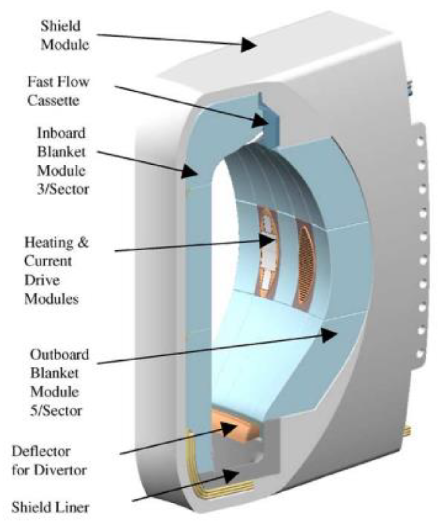
- Elio, F.; Ioki, K.; Yamada, M.; Strebkov, Y.; Daenner, W.; Akiba, M. Design and R&D Progress of Blanket Attachments. Fusion Eng. Des. 2003, 69, 321–326. [Google Scholar] [CrossRef]
- Stubbins, J.F.; Kurath, P.; Drockelman, D.; Morgan, G.D.; McAfee, J.; Li, G.; Thomas, B.G. Analysis of Copper Alloy to Stainless Steel Bonded Panels for ITER First Wall Applications. In Proceedings of the 16th International Symposium on Fusion Engineering, 6 August 2002; IEEE: Piscataway, NJ, USA, 2002; Volume 1, pp. 174–177. [Google Scholar] [CrossRef]
- Sato, S.; Kuroda, T.; Hatano, T.; Furuya, K.; Tokami, I.; Takatsu, H. Development of First Wall/Blanket Structure by Hot Isostatic Pressing (HIP) in the JAERI. Fusion Eng. Des. 1998, 39–40, 609–614. [Google Scholar] [CrossRef]
- Fabritsiev, S.A.; Pokrovsky, A.S.; Edwards, D.J.; Zinkle, S.J.; Rowcliffe, A.F. Effect of Neutron Irradiation on the Mechanical Properties and Fracture Mode of Cu/Ss Joints. Plasma Devices Oper. 2001, 8, 225–239. [Google Scholar] [CrossRef]
- Le Marois, G.; Burlet, H.; Solomon, R.; Marini, B.; Gentzbittel, J.; Briottet, L. Structural Materials Joints for ITER In-Vessel Components. Fusion Eng. Des. 1998, 39–40, 253–261. [Google Scholar] [CrossRef]
- Le Marois, G.; Dellis, C.; Gentzbittel, J.M.; Moret, F. HIP’ing of Copper Alloys to Stainless Steel. J. Nucl. Mater. 1996, 233–237, 927–931. [Google Scholar] [CrossRef]
- Xu, Q.; Yoshiie, T.; Muroga, T.; Yoshida, N.; Iwai, T.; Edwards, D. Microstructural Evolution and Hardness Changes in the Interface of Cu/316L Joint Materials under Aging and Ion Irradiation. J. Nucl. Mater. 2004, 329–333, 1558–1562. [Google Scholar] [CrossRef]
- Park, J.-Y.; Choi, B.-K.; Kim, H.-G.; Kim, J.-H.; Lee, M.-H.; Park, S.-Y.; Hong, B.G.; Jeong, Y.H. Optimization of Joining Condition for ITER First Wall Fabrication. J. Korean Phys. Soc. 2006, 49 (Suppl. 1), 442–446. [Google Scholar]
- Park, J.-Y.; Choi, B.-K.; Lee, J.-S.; Lee, D.W.; Hong, B.G.; Jeong, Y.H. Fabrication of Be/CuCrZr/SS Mock-Ups for ITER First Wall. Fusion Eng. Des. 2009, 84, 1468–1471. [Google Scholar] [CrossRef]
- Tähtinen, S.; Laukkanen, A.; Singh, B. Investigations of Copper to Stainless Steel Joints. Fusion Eng. Des. 2001, 56–57, 391–396. [Google Scholar] [CrossRef]
- Daenner, W.; Merola, M.; Lorenzetto, P.; Peacock, A.; Bobin-Vastra, I.; Briottet, L.; Bucci, P.; Conchon, D.; Erskine, A.; Escourbiac, F.; et al. Status of Fabrication Development for Plasma Facing Components in the EU. Fusion Eng. Des. 2002, 61–62, 61–70. [Google Scholar] [CrossRef]
- Elio, F.; Ioki, K.; Barabaschi, P.; Bruno, L.; Cardella, A.; Hechler, M.; Kodama, T.; Lodato, A.; Loesser, D.; Lousteau, D.; et al. Engineering Design of the ITER Blanket and Relevant Research and Development Results. Fusion Eng. Des. 1999, 46, 159–175. [Google Scholar] [CrossRef]
- Elangovan, K.; Balasubramanian, V. Influences of Tool Pin Profile and Welding Speed on the Formation of Friction Stir Processing Zone in AA2219 Aluminium Alloy. J. Mater. Process. Technol. 2008, 200, 163–175. [Google Scholar] [CrossRef]
- Leedy, K.; Stubbins, J. Copper Alloy–Stainless Steel Bonded Laminates for Fusion Reactor Applications: Tensile Strength and Microstructure. Mater. Sci. Eng. A 2001, 297, 10–18. [Google Scholar] [CrossRef]
- Spence, P.J.; Hall, F.R.; Emekwuru, N. Preliminary Study of Improving the Speed and Cost of Diffusion Bonding of Metal Sheets. Proc. Inst. Mech. Eng. Part B J. Eng. Manuf. 2014, 228, 95–110. [Google Scholar] [CrossRef]
- Testani, C.; Ferraro, F.; Deodati, P.; Donnini, R.; Montanari, R.; Kaciulis, S.; Mezzi, A. Comparison between Roll Diffusion Bonding and Hot Isostatic Pressing Production Processes of Ti6Al4V-SiCf Metal Matrix Composites. Mater. Sci. Forum 2011, 678, 145–154. [Google Scholar] [CrossRef]
- Yilmaz, O.; Çelik, H. Electrical and Thermal Properties of the Interface at Diffusion-Bonded and Soldered 304 Stainless Steel and Copper Bimetal. J. Mater. Process. Technol. 2003, 141, 67–76. [Google Scholar] [CrossRef]
- Yuan, X.; Tang, K.; Deng, Y.; Luo, J.; Sheng, G. Impulse Pressuring Diffusion Bonding of a Copper Alloy to a Stainless Steel with/without a Pure Nickel Interlayer. Mater. Des. 2013, 52, 359–366. [Google Scholar] [CrossRef]
- Nishi, H.; Kikuchi, K. Influence of Brazing Conditions on the Strength of Brazed Joints of Alumina Dispersion-Strengthened Copper to 316 Stainless Steel. J. Nucl. Mater. 1998, 258–263, 281–288. [Google Scholar] [CrossRef]
- Kaya, Y.; Kahraman, N.; Durgutlu, A.; Gülenç, B. A Novel Approach to Diffusion Bonding of Copper to Stainless Steel. Proc. Inst. Mech. Eng. Part B J. Eng. Manuf. 2012, 226, 478–484. [Google Scholar] [CrossRef]
- Sabetghadam, H.; Zarei Hanzaki, A.; Araee, A.; Hadian, A. Microstructural Evaluation of 410 SS/Cu Diffusion-Bonded Joint. J. Mater. Sci. Technol. 2010, 26, 163–169. [Google Scholar] [CrossRef]
- Lorenzetto, P.; Peacock, A.; Bobin-Vastra, I.; Briottet, L.; Bucci, P.; Dell’Orco, G.; Ioki, K.; Roedig, M.; Sherlock, P. EU R&D on the ITER First Wall. Fusion Eng. Des. 2006, 81 A, 355–360. [Google Scholar] [CrossRef]
- Yilmaz, O.; Aksoy, M. Investigation of Micro-Crack Occurrence Conditions in Diffusion Bonded Cu-304 Stainless Steel Couple. J. Mater. Process. Technol. 2002, 121, 136–142. [Google Scholar] [CrossRef]
- Xiong, J.T.; Xie, Q.; Li, J.L.; Zhang, F.S.; Huang, W.D. Diffusion Bonding of Stainless Steel to Copper with Tin Bronze and Gold Interlayers. J. Mater. Eng. Perform. 2012, 21, 33–37. [Google Scholar] [CrossRef]
- Nishi, H.; Araki, T. Low Cycle Fatigue Strength of Diffusion Bonded Joints of Alumina Dispersion-Strengthened Copper to Stainless Steel. J. Nucl. Mater. 2000, 283–287, 1234–1237. [Google Scholar] [CrossRef]
- Nishi, H. Notch Toughness Evaluation of Diffusion-Bonded Joint of Alumina Dispersion-Strengthened Copper to Stainless Steel. Fusion Eng. Des. 2006, 81 A, 269–274. [Google Scholar] [CrossRef]
- Findik, F. Recent Developments in Explosive Welding. Mater. Des. 2011, 32, 1081–1093. [Google Scholar] [CrossRef]
- Durgutlu, A.; Gülenç, B.; Findik, F. Examination of Copper/Stainless Steel Joints Formed by Explosive Welding. Mater. Des. 2005, 26, 497–507. [Google Scholar] [CrossRef]
- Honarpisheh, M.; Haddadi, A.A.; Mansouri, H. The Effect of Annealing Heat Treatment on the Bond of Explosive—Welded Copper/Steel after the ECAR Process. J. Mod. Process. Manuf. Prod. 2018, 6, 77–86. [Google Scholar]
- Ma, R.; Wang, Y.; Wu, J.; Duan, M. Explosive Welding Method for Manufacturing ITER-Grade 316L(N)/CuCrZr Hollow Structural Member. Fusion Eng. Des. 2014, 89, 3117–3124. [Google Scholar] [CrossRef]
- Durgutlu, A.; Okuyucu, H.; Gulenc, B. Investigation of Effect of the Stand-off Distance on Interface Characteristics of Explosively Welded Copper and Stainless Steel. Mater. Des. 2008, 29, 1480–1484. [Google Scholar] [CrossRef]
- Yang, M.; Ma, H.; Shen, Z.; Sun, Y. Study on Explosive Welding for Manufacturing Meshing Bonding Interface of CuCrZr to 316L Stainless Steel. Fusion Eng. Des. 2019, 143, 106–114. [Google Scholar] [CrossRef]
- Lorenzetto, P.; Boireau, B.; Boudot, C.; Bucci, P.; Furmanek, A.; Ioki, K.; Liimatainen, J.; Peacock, A.; Sherlock, P.; Tähtinen, S. Manufacture of Blanket Shield Modules for ITER. Fusion Eng. Des. 2005, 75–79, 291–296. [Google Scholar] [CrossRef]
- Wang, P.; Chen, J.; Li, Q.; Liu, D.; Huang, P.; Jin, F.; Zhou, Y.; Yang, B. Study on the Microstructure and Properties Evolution of CuCrZr/316LN-IG Explosion Bonding for ITER First Wall Components. Fusion Eng. Des. 2017, 124, 1135–1139. [Google Scholar] [CrossRef]
- Livne, Z.; Munitz, A. Characterization of Explosively Bonded Iron and Copper Plates. J. Mater. Sci. 1987, 22, 1495–1500. [Google Scholar] [CrossRef]
- Sahin, A.Z.; Yibaş, B.S.; Ahmed, M.; Nickel, J. Analysis of the Friction Welding Process in Relation to the Welding of Copper and Steel Bars. J. Mater. Process. Technol. 1998, 82, 127–136. [Google Scholar] [CrossRef]
- Sahin, M. Joining of Stainless Steel and Copper Materials with Friction Welding. Ind. Lubr. Tribol. 2009, 61, 319–324. [Google Scholar] [CrossRef]
- Chinnakannan, S. Friction Welding of Austenitic Stainless Steel with Copper Material. In Austenitic Stainless Steels—New Aspects; InTech: London, UK, 2017. [Google Scholar] [CrossRef] [Green Version]
- Shanjeevi, C.; Arputhabalan, J.J.; Dutta, R. Pradeep. Investigation on the Effect of Friction Welding Parameters on Impact Strength in Dissimilar Joints. IOP Conf. Ser. Mater. Sci. Eng. 2017, 197, 012069. [Google Scholar] [CrossRef] [Green Version]
- Tsuchiya, K.; Kawamura, H. Mechanical Properties of CuCrZr Alloy and SS316 Joints Fabricated by Friction Welding Method. J. Nucl. Mater. 1996, 233–237, 913–917. [Google Scholar] [CrossRef]
- Shokri, V.; Sadeghi, A.; Sadeghi, M.H. Thermomechanical Modeling of Friction Stir Welding in a Cu-DSS Dissimilar Joint. J. Manuf. Process. 2018, 31, 46–55. [Google Scholar] [CrossRef]
- Shokri, V.; Sadeghi, A.; Sadeghi, M.H. Effect of Friction Stir Welding Parameters on Microstructure and Mechanical Properties of DSS–Cu Joints. Mater. Sci. Eng. A 2017, 693, 111–120. [Google Scholar] [CrossRef] [Green Version]
- Ramirez, A.J.; Benati, D.M.; Fals, H.C. Effect of Tool Offset On Dissimilar Cu-AISI 316 Stainless Steel Friction Stir Welding. In Proceedings of the 21st International Offshore and Polar Engineering Conference, Maui, Hawaii, USA, 19–24 June 2011; Volume 8, pp. 548–551. [Google Scholar]
- Akella, M.S.; Harinadh, M.V.; Krishna, M.Y.; Buddu, M.R.K. A Welding Simulation of Dissimilar Materials SS304 and Copper. Procedia Mater. Sci. 2014, 5, 2440–2449. [Google Scholar] [CrossRef] [Green Version]
- Najafkhani, A.; Zangeneh-Madar, K.; Abbaszadeh, H. Evaluation of Microstructure and Mechanical Properties of Friction Stir Welded Copper/316L Stainless Steel Dissimilar Metals. Int. J. ISSI 2010, 7, 21–25. [Google Scholar]
- Imani, Y.; Givi, M.K.B.; Guillot, M. Improving Friction Stir Welding between Copper and 304L Stainless Steel. Adv. Mater. Res. 2011, 409, 263–268. [Google Scholar] [CrossRef]
- Aval, H.J. Microstructural Evolution and Mechanical Properties of Friction Stir-Welded C71000 Copper–Nickel Alloy and 304 Austenitic Stainless Steel. Int. J. Miner. Metall. Mater. 2018, 25, 1294–1303. [Google Scholar] [CrossRef]
- Jafari, M.; Abbasi, M.; Poursina, D.; Gheysarian, A.; Bagheri, B. Microstructures and Mechanical Properties of Friction Stir Welded Dissimilar Steel-Copper Joints. J. Mech. Sci. Technol. 2017, 31, 1135–1142. [Google Scholar] [CrossRef]
- Sahlot, P.; Nene, S.S.; Frank, M.; Mishra, R.S.; Arora, A. Towards Attaining Dissimilar Lap Joint of CuCrZr Alloy and 316L Stainless Steel Using Friction Stir Welding. Sci. Technol. Weld. Join. 2018, 23, 715–720. [Google Scholar] [CrossRef]
- Wang, T.; Shukla, S.; Nene, S.S.; Frank, M.; Wheeler, R.W.; Mishra, R.S. Towards Obtaining Sound Butt Joint Between Metallurgically Immiscible Pure Cu and Stainless Steel Through Friction Stir Welding. Metall. Mater. Trans. A 2018, 49, 2578–2582. [Google Scholar] [CrossRef]
- Joshi, G.R.; Badheka, V.J. Studies on Tool Shoulder Diameter of Dissimilar Friction Stir Welding Copper to Stainless Steel. Metallogr. Microstruct. Anal. 2019, 8, 263–274. [Google Scholar] [CrossRef]
- Joshi, G.R.; Badheka, V.J. Microstructures and Properties of Copper to Stainless Steel Joints by Hybrid FSW. Metallogr. Microstruct. Anal. 2017, 6, 470–480. [Google Scholar] [CrossRef]
- Wei, R.; Li, Q.; Wang, W.J.; Wang, J.C.; Wang, X.L.; Xie, C.Y.; Luo, G.-N. Microstructure and Properties of W-Cu/CuCrZr/316L Joint Bonded by One-Step HIP Technique. Fusion Eng. Des. 2018, 128, 47–52. [Google Scholar] [CrossRef]
- Lee, D.W.; Bae, Y.D.; Kim, S.K.; Hong, B.G.; Jung, H.K.; Park, J.Y.; Jeong, Y.H.; Choi, B.K. High Heat Flux Test with Hip Bonded 50×50 Be/Cu Mock-Ups for the Iter First Wall. Fusion Sci. Technol. 2009, 56, 48–51. [Google Scholar] [CrossRef]
- Ivanov, A.D.; Sato, S.; Le Marois, G. Evaluation of Hot Isostatic Pressing for Joining of Fusion Reactor Structural Components. J. Nucl. Mater. 2000, 283–287, 35–42. [Google Scholar] [CrossRef]
- Orsag, M.; Bogdan, S. Hybrid Control of Quadrotor. In Proceedings of the 2009 17th Mediterranean Conference on Control and Automation, Thessaloniki, Greece, 24–26 June 2009; IEEE: Piscataway, NJ, USA; Volume 1, pp. 1239–1244. [Google Scholar] [CrossRef]
- Madhusudhan Reddy, G.; Mohandas, T.; Sambasiva Rao, A.; Satyanarayana, V.V. Influence of welding processes on microstructure and mechanical properties of dissimilar austenitic-ferritic stainless steel welds. Mater. Manuf. Process. 2005, 20, 147–173. [Google Scholar] [CrossRef]
- Senthilkumar, G.; Ramakrishnan, R. Design of Optimal Parameter for Solid-State Welding of EN 10028-P355 GH Steel Using Gray Incidence Reinforced Response Surface Methodology. Arab. J. Sci. Eng. 2021, 46, 2613–2628. [Google Scholar] [CrossRef]
- Carlone, P.; Astarita, A.; Palazzo, G.S.; Paradiso, V.; Squillace, A. Microstructural Aspects in Al–Cu Dissimilar Joining by FSW. Int. J. Adv. Manuf. Technol. 2015, 79, 1109–1116. [Google Scholar] [CrossRef]
- Parikh, V.K.; Badgujar, A.D.; Ghetiya, N.D. Joining of Metal Matrix Composites Using Friction Stir Welding: A Review. Mater. Manuf. Process. 2019, 34, 123–146. [Google Scholar] [CrossRef]
- Marques, E.S.V.; Silva, F.J.G.; Pereira, A.B. Comparison of Finite Element Methods in Fusion Welding Processes—A Review. Metals 2020, 10, 75. [Google Scholar] [CrossRef] [Green Version]
- Annamalai, A.; Babu, T.R.K.; Karthikeyan, S.; Siddharth, N.; Muralidharan, S. Study of Friction Stir Welding on Aerospace Grade ZE41AMg Alloy and Its Comparison with Laser Beam Welding on ZE41AMg Alloy; Springer: Singapore, 2021. [Google Scholar] [CrossRef]
- DebRoy, T.; Bhadeshia, H.K.D.H. Stirring Solid Metals to Form Sound Welds. In Innovations in Everyday Engineering Materials; Springer International Publishing: Cham, Switzerland, 2021. [Google Scholar] [CrossRef]
- Aminzadeh, A.; Parvizi, A.; Safdarian, R.; Rahmatabadi, D. Comparison between Laser Beam and Gas Tungsten Arc Tailored Welded Blanks via Deep Drawing. Proc. Inst. Mech. Eng. Part B J. Eng. Manuf. 2021, 235, 673–688. [Google Scholar] [CrossRef]
- Abdou, M.; Sze, D.; Wong, C.; Sawan, M.; Ying, A.; Morley, N.B.; Malang, S.U.S. Plans and Strategy for ITER Blanket Testing. Fusion Sci. Technol. 2005, 47, 475–487. [Google Scholar] [CrossRef]
- Zinkle, S.J.; Möslang, A.; Muroga, T.; Tanigawa, H. Multimodal Options for Materials Research to Advance the Basis for Fusion Energy in the ITER Era. Nucl. Fusion 2013, 53, 104024. [Google Scholar] [CrossRef]
- Nygren, R.E.; Rognlien, T.D.; Rensink, M.E.; Smolentsev, S.S.; Youssef, M.Z.; Sawan, M.E.; Merrill, B.J.; Eberle, C.; Fogarty, P.J.; Nelson, B.E.; et al. A Fusion Reactor Design with a Liquid First Wall and Divertor. Fusion Eng. Des. 2004, 72, 181–221. [Google Scholar] [CrossRef] [Green Version]
- Chai, K.-B.; Kwon, D.-H. Heat and Particle Load Test Facility Using an Applied-Field MPD Thruster for Studying Fusion Divertor Technology. Plasma Phys. Control. Fusion 2020, 62, 035007. [Google Scholar] [CrossRef]
- Mercy Latha, A.; Ghosh, S.K. A Comprehensive Review of Depressed Collectors of Slow-Wave Devices. J. Electromagn. Waves Appl. 2021, 35, 95–137. [Google Scholar] [CrossRef]
- Kato, I. Status of the T2K Experiment. J. Phys. Conf. Ser. 2008, 136, 022018. [Google Scholar] [CrossRef]
- Chu, D.; Jiang, H.; Deng, H.; Yang, J.; Wang, W. Preliminary Experimental Study on Hypervapotron Heat Transfer for High Heat Flux Components. IEEE Trans. Plasma Sci. 2018, 46, 1372–1376. [Google Scholar] [CrossRef]
- Tao, L.; Hu, C.; Xie, Y. Enhanced Heat Transfer Structure Design for Ion Dump of EAST-NBI System Based on Hypervapotron. In Volume 2: Plant Systems, Structures, Components and Materials; American Society of Mechanical Engineers: New York, NY, USA, 2017. [Google Scholar] [CrossRef]
- Ghule, K.; Yadav, S.S. Investigation of Boiling inside a Hypervapotron with Different Fin Geometries. In Proceeding of the 24th National and 2nd International ISHMT-ASTFE Heat and Mass Transfer Conference (IHMTC-2017), Hyderabad, India, 27–30 December 2017; Begellhouse: Danbury, CT, USA, 2018; pp. 467–474. [Google Scholar] [CrossRef]
- Rensing, C.; Grass, G. Escherichia Coli Mechanisms of Copper Homeostasis in a Changing Environment. FEMS Microbiol. Rev. 2003, 27, 197–213. [Google Scholar] [CrossRef] [Green Version]
- Cava, R.J. Structural Chemistry and the Local Charge Picture of Copper Oxide Superconductors. Science 1990, 247, 656–662. [Google Scholar] [CrossRef]
- Cava, R.J.; Batlogg, B.; Krajewski, J.J.; Rupp, L.W.; Schneemeyer, L.F.; Siegrist, T.; VanDover, R.B.; Marsh, P.; Peck, W.F.; Gallagher, P.K.; et al. Superconductivity near 70 K in a New Family of Layered Copper Oxides. Nature 1988, 336, 211–214. [Google Scholar] [CrossRef]
- Richardson, C.; Steel, P.J. Benzotriazole as a Structural Component in Chelating and Bridging Heterocyclic Ligands; Ruthenium, Palladium, Copper and Silver Complexes. Dalt. Trans. 2003, 5, 992–1000. [Google Scholar] [CrossRef]
- Ye, X.B.; He, Z.H.; Pan, B.C. The Thermal Conductivity of Defected Copper at Finite Temperatures. J. Mater. Sci. 2020, 55, 4453–4463. [Google Scholar] [CrossRef]
- Muroga, T.; Noto, H.; Hishinuma, Y.; Huang, B. Technical Advancement in Fabricating Dispersion Strengthened Copper Alloys by Mechanical Alloying and Hot Isostatic Pressing for Application to Divertors of Fusion Reactors. Mater. Sci. Forum 2018, 941, 778–783. [Google Scholar] [CrossRef]
- Ye, C. Experimental Investigation of Copper/Stainless Steel Joints Formed by Vacuum Brazing. In Proceedings of the 18th International Conference on Nuclear Engineering: Volume 5, ASMEDC, Xi’an, China, 17–21 May 2010; pp. 47–55. [Google Scholar] [CrossRef]
- Swami, H.L.; Danani, C.; Shaw, A.K. Activation Characteristics of Candidate Structural Materials for a Near-Term Indian Fusion Reactor and the Impact of Their Impurities on Design Considerations. Plasma Sci. Technol. 2018, 20, 065602. [Google Scholar] [CrossRef] [Green Version]
- Ali, N.M.; Saeed, A.; El Shazly, R.M.; Al-Fiki, S.A.; Eissa, M.M.; El-kameesy, S.U. Attenuation Effectiveness of Double Phase Stainless Steel Alloys for Fusion Reactor System. IOP Conf. Ser. Mater. Sci. Eng. 2020, 956, 012008. [Google Scholar] [CrossRef]
- Tamura, H.; Yanagi, N.; Goto, T.; Miyazawa, J.; Tanaka, T.; Sagara, A.; Ito, S.; Hashizume, H. Mechanical Design Concept of Superconducting Magnet System for Helical Fusion Reactor. Fusion Sci. Technol. 2019, 75, 384–390. [Google Scholar] [CrossRef]
- Şahin, S.; Şahin, H.M.; Şahiner, H.; Tunç, G. Study on the Fusion Reactor Performance with Different Materials and Nuclear Waste Actinides. Int. J. Energy Res. 2020, 45, 11759–11774. [Google Scholar] [CrossRef]
- Lee, D.W.; Bae, Y.D.; Hong, B.G.; Wang, S.J.; Park, J.Y.; Jeong, Y.H.; Jeong, H.K.; Lee, J.H. Development of Fabrication and Qualification Methods for the First Wall of the International Thermonuclear Experimental Reactor. J. Korean Phys. Soc. 2007, 51, 1210. [Google Scholar] [CrossRef]
- Nishi, H.; Araki, T.; Eto, M. Diffusion Bonding of Alumina Dispersion-Strengthened Copper to 316 Stainless Steel with Interlayer Metals. Fusion Eng. Des. 1998, 39–40, 505–511. [Google Scholar] [CrossRef]
- Sabetghadam, H.; Hanzaki, A.Z.; Araee, A. Diffusion Bonding of 410 Stainless Steel to Copper Using a Nickel Interlayer. Mater. Charact. 2010, 61, 626–634. [Google Scholar] [CrossRef]
- Goods, S.H.; Puskar, J.D. Solid State Bonding of CuCrZr to 316L Stainless Steel for ITER Applications. Fusion Eng. Des. 2011, 86, 1634–1638. [Google Scholar] [CrossRef]
- CUI, Y.; XU, C.; HAN, Q. Effect of Ultrasonic Vibration on Unmixed Zone Formation. Scr. Mater. 2006, 55, 975–978. [Google Scholar] [CrossRef]
- Desai, N.B.; Kedare, S.B.; Bandyopadhyay, S. Optimization of Design Radiation for Concentrating Solar Thermal Power Plants without Storage. Sol. Energy 2014, 107, 98–112. [Google Scholar] [CrossRef]
- Vairis, A.; Frost, M. Design and Commissioning of a Friction Welding Machine. Mater. Manuf. Process. 2006, 21, 766–773. [Google Scholar] [CrossRef]
- Bayindir, R.; Ates, H. Comparison of the Constructed Control Methods for a Friction-Welding Machine. Mater. Manuf. Process. 2005, 20, 131–146. [Google Scholar] [CrossRef]
- Msomi, V.; Moni, V. The Influence of Materials Positioning on Microstructure and Mechanical Properties of Friction Stir Welded AA5083/AA6082 Dissimilar Joint. Adv. Mater. Process. Technol. 2021, 1–15. [Google Scholar] [CrossRef]
- Das, D.; Jaypuria, S.; Pratihar, D.K.; Roy, G.G. Weld Optimisation. Sci. Technol. Weld. Join. 2021, 26, 181–195. [Google Scholar] [CrossRef]
- Rehman, A.U.; Babu, N.K.; Talari, M.K.; Usmani, Y.S.; Al-Khalefah, H. Microstructure and Mechanical Properties of Dissimilar Friction Welding Ti-6Al-4V Alloy to Nitinol. Metals 2021, 11, 109. [Google Scholar] [CrossRef]
- Srinivas, K.; Saranarayanan, R.; Lakshminarayanan, A.K.; Srinivasan, N.; Venkatraman, B. Zone Wise Properties of Friction Stir Welded Copper—Stainless Steel Joints Using Digital Image Correlation. Appl. Mech. Mater. 2015, 787, 485–489. [Google Scholar] [CrossRef]
- Murr, L.E. A Review of FSW Research on Dissimilar Metal and Alloy Systems. J. Mater. Eng. Perform. 2010, 19, 1071–1089. [Google Scholar] [CrossRef]
- Wan, L.; Huang, Y. Friction Stir Welding of Dissimilar Aluminum Alloys and Steels: A Review. Int. J. Adv. Manuf. Technol. 2018, 99, 1781–1811. [Google Scholar] [CrossRef]
- Mehta, K.P.; Badheka, V.J. Effects of Tilt Angle on the Properties of Dissimilar Friction Stir Welding Copper to Aluminum. Mater. Manuf. Process. 2016, 31, 255–263. [Google Scholar] [CrossRef]
- Mehta, K.P.; Badheka, V.J. Influence of Tool Design and Process Parameters on Dissimilar Friction Stir Welding of Copper to AA6061-T651 Joints. Int. J. Adv. Manuf. Technol. 2015, 80, 2073–2082. [Google Scholar] [CrossRef]
- Windows, M.; Os, M.; When, C.P.; Wei, Y.; Yildirim, P.; den Bulte, C.; Dellarocas, C.; Weekly, T.; Weekly, I.C.T.I.; Henley, W.E.; et al. Advances in Friction Stir Welding and Proccessing; Woodhead Publishing: Sawston, UK, 2014; Volume XXXIII. [Google Scholar] [CrossRef]
- Mehta, K.P.; Badheka, V.J. A Review on Dissimilar Friction Stir Welding of Copper to Aluminum: Process, Properties, and Variants. Mater. Manuf. Process. 2016, 31, 233–254. [Google Scholar] [CrossRef]
- Ahmad Shah, L.H.; Midawi, A.; Walbridge, S.; Gerlich, A. Influence of Tool Offsetting and Base Metal Positioning on the Material Flow of AA5052-AA6061 Dissimilar Friction Stir Welding. J. Mech. Eng. Sci. 2020, 14, 6393–6402. [Google Scholar] [CrossRef] [Green Version]
- Mallieswaran, K.; Padmanabhan, R. Effect of Sheet Thickness on the FSW Parameters for Dissimilar Aluminium Grades Tailor Welded Blanks. Adv. Mater. Process. Technol. 2020, 7, 1–16. [Google Scholar] [CrossRef]
- Kasman, S. The Effects of Pin Offset for FSW of Dissimilar Materials: A Study for AA 7075—AA 6013. Matéria 2020, 25, 1–14. [Google Scholar] [CrossRef]
- Ghiasvand, A.; Kazemi, M.; Mahdipour Jalilian, M.; Ahmadi Rashid, H. Effects of Tool Offset, Pin Offset, and Alloys Position on Maximum Temperature in Dissimilar FSW of AA6061 and AA5086. Int. J. Mech. Mater. Eng. 2020, 15, 6. [Google Scholar] [CrossRef]
- Thomas, W.M.; Threadgill, P.L.; Nicholas, E.D. Feasibility of Friction Stir Welding Steel. Sci. Technol. Weld. Join. 1999, 4, 365–372. [Google Scholar] [CrossRef]
- Zhang, Y.N.; Cao, X.; Larose, S.; Wanjara, P. Review of Tools for Friction Stir Welding and Processing. Can. Metall. Q. 2012, 51, 250–261. [Google Scholar] [CrossRef]
- Prater, T. Solid-State Joining of Metal Matrix Composites: A Survey of Challenges and Potential Solutions. Mater. Manuf. Process. 2011, 26, 636–648. [Google Scholar] [CrossRef]
- Chandrashekar, A.; Kumar, B.S.A.; Reddappa, H.N. Friction Stir Welding: Tool Material and Geometry. AKGEC Int. J. Technol. 2015, 6, 16–20. [Google Scholar]
- Shindo, D.J.; Rivera, A.R.; Murr, L.E. Shape Optimization for Tool Wear in the Friction-Stir Welding of Cast Al359-20% SiC MMC. J. Mater. Sci. 2002, 37, 4999–5005. [Google Scholar] [CrossRef]
- Eff, M. The Effects of Tool Texture on Tool Wear in Friction Stir Welding of X-70 Steel; The Ohio State University: Columbus, OH, USA, 2012. [Google Scholar]
- Tiwari, A.; Pankaj, P.; Suman, S.; Singh, P.; Biswas, P.; Pal, S.; Rao, A.G. Effect of Plasma Preheating on Weld Quality and Tool Life during Friction Stir Welding of DH36 Steel. Proc. Inst. Mech. Eng. Part B J. Eng. Manuf. 2021, 235, 1458–1472. [Google Scholar] [CrossRef]
- Lauterbach, D.; Keil, D.; Harms, A.; Leupold, C.; Dilger, K. Tool Wear Behaviour and the Influence of Wear-Resistant Coatings during Refill Friction Stir Spot Welding of Aluminium Alloys. Weld. World 2021, 65, 243–250. [Google Scholar] [CrossRef]
- Vicharapu, B.; Lemos, G.V.B.; Bergmann, L.; dos Santos, J.F.; De, A.; Clarke, T. Probing Underlying Mechanisms for PCBN Tool Decay during Friction Stir Welding of Nickel-Based Alloys. Tecnol. em Metal. Mater. Min. 2021, 18, e2455. [Google Scholar] [CrossRef]
- Stewart, H.A. Cryogenic Treatment of Tungsten Carbide Reduces Tool Wear When Machining Medium Density Fiberboard. For. Prod. J. 2004, 54, 53–56. [Google Scholar]
- Gill, S.S.; Singh, J.; Singh, H.; Singh, R. Metallurgical and Mechanical Characteristics of Cryogenically Treated Tungsten Carbide (WC–Co). Int. J. Adv. Manuf. Technol. 2012, 58, 119–131. [Google Scholar] [CrossRef]
- Gill, S.S.; Singh, J.; Singh, R.; Singh, H. Metallurgical Principles of Cryogenically Treated Tool Steels—A Review on the Current State of Science. Int. J. Adv. Manuf. Technol. 2011, 54, 59–82. [Google Scholar] [CrossRef]
- Akıncıoğlu, G. Investigation of the Effect of Cryogenic Treatment Cubic Boron Nitride Turning Insert Tools. J. Mater. Eng. Perform. 2021, 30, 1280–1288. [Google Scholar] [CrossRef]
- Yooliengpun, C.; Bandasak, N.; Tuchinda, K.; Diewwanit, O. Effect of Cryogenic Treatment of Cemented Tungsten Carbide Tools for Die Application. IOP Conf. Ser. Mater. Sci. Eng. 2021, 1048, 012002. [Google Scholar] [CrossRef]
- Parida, B.; Vishwakarma, S.D.; Pal, S. Design and Development of Fixture and Force Measuring System for Friction Stir Welding Process Using Strain Gauges. J. Mech. Sci. Technol. 2015, 29, 739–749. [Google Scholar] [CrossRef]
- Yaduwanshi, D.K.; Bag, S.; Pal, S. Hybrid Friction Stir Welding of Similar and Dissimilar Materials. In Proceedings of the 5th international and 26th all India Manufacturing Technology, Delhi, India, 12–14 December 2014; pp. 323–347. [Google Scholar]
- Yaduwanshi, D.K.; Bag, S.; Pal, S. On the Effect of Tool Offset in Hybrid-FSW of Copper-Aluminium Alloy. Mater. Manuf. Process. 2018, 33, 277–287. [Google Scholar] [CrossRef]
- Sinclair, P.C.; Longhurst, W.R.; Cox, C.D.; Lammlein, D.H.; Strauss, A.M.; Cook, G.E. Heated Friction Stir Welding: An Experimental and Theoretical Investigation into How Preheating Influences Process Forces. Mater. Manuf. Process. 2010, 25, 1283–1291. [Google Scholar] [CrossRef]
- Kim, K.-H.; Bang, H.-S.; Ro, C.-S.; Bang, H.-S. Influence of Preheating Source on Mechanical Properties and Welding Residual Stress Characteristics in Ultra Thin Ferritic Stainless Steel Hybrid Friction Stir Welded Joints. Int. J. Precis. Eng. Manuf. Technol. 2017, 4, 393–400. [Google Scholar] [CrossRef]
- Joo, S. Joining of Dissimilar AZ31B Magnesium Alloy and SS400 Mild Steel by Hybrid Gas Tungsten Arc Friction Stir Welding. Met. Mater. Int. 2013, 19, 1251–1257. [Google Scholar] [CrossRef]
- Liu, H.J.; Zhang, H.J. Study of Hybrid Welding Repair Process of Friction Stir Welding Grove Defect. Sci. Technol. Weld. Join. 2012, 17, 169–173. [Google Scholar] [CrossRef]
- Li, X.; Chen, S.; Yuan, T.; Jiang, X.; Han, Y. Improving the Properties of Friction Stir Welded 2219-T87 Aluminum Alloy with GTA Offset Preheating. J. Manuf. Process. 2020, 51, 10–18. [Google Scholar] [CrossRef]
- Satpathy, M.P.; Kumar, A.; Sahoo, S.K. Effect of Brass Interlayer Sheet on Microstructure and Joint Performance of Ultrasonic Spot-Welded Copper-Steel Joints. J. Mater. Eng. Perform. 2017, 26, 3254–3262. [Google Scholar] [CrossRef]
- Kore, S.D.; Date, P.P.; Kulkarni, S.V.; Kumar, S.; Rani, D.; Kulkarni, M.R.; Desai, S.V.; Rajawat, R.K.; Nagesh, K.V.; Chakravarty, D.P. Application of Electromagnetic Impact Technique for Welding Copper-to-Stainless Steel Sheets. Int. J. Adv. Manuf. Technol. 2011, 54, 949–955. [Google Scholar] [CrossRef]


| Substrate | Thickness (mm) | Joint Design | Parameters | Testing Method | Maximum Obtained Properties of the Joint | Reference |
|---|---|---|---|---|---|---|
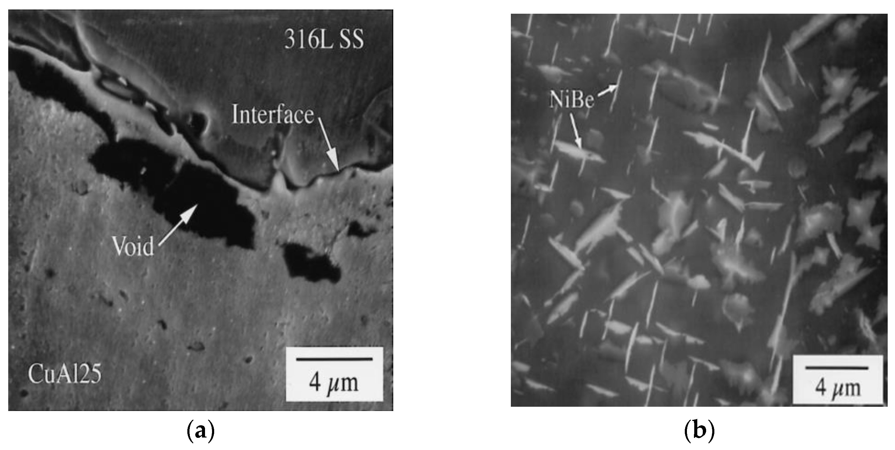
| Joint 1 CuAl15/316 SS Joint 2 CuNiBe/316 SS Joint 3 CuAl25/316 SS | 6/6, 15/10, 15/10 | Not reported | Joint 1 & 3 Temperature; 982 °C Pressure: 102 MPa Holding time: 2 h Joint 2 Temperature; 927 °C Pressure: 102 MPa Holding time: 2 h Aged at 500 °C for six h | Tensile test Shear strength test Microstructure SEM EDX AES TEM | UTS (MPa): 290 for joint 1 Shear strength (MPa): 120–125 for joint 2 | [89] |
| DSCu (GlidCop® AL-15 and AL-25)/SS | 1.5 | Tube-plate joint | Temperature; 980 °C, 1030 °C, 1050 °C Pressure: 150 MPa Holding time: 2 h | Tensile test, SEM Microstructure Charpy impact test Fatigue strength test Fracture toughness test Crack propagation test EPMA analysis Microhardness, Heat flux test | Optimum process temperature: 1050 °C | [153] |
| Joint 1 GlidCop A125/316 LN SS Joint 2 Cu-Cr-Zr/316 LN SS Joint 3 GlidCop A125/316 SS | Joint 1 25/40 | Not reported | Joint 1 Temperature (°C); 920, 1000 Pressure (MPa): 100, 140 Holding time (min) 70, 180 Joint 2 Temperature: 1000 °C Pressure: 140 MPa Holding time: 70 min Joint 3 Temperature (°C); 1050 Pressure (MPa): 150 Holding time (h): 2 | Tensile test Microstructure | UTS: 415 MPa Optimum condition Joint 3 | [80] |
| Joint 1 DSCu/316LN SS Joint 2 DSCu/316L SS Joint 3 CuCrZr/316LN SS | Not reported | Not reported | Joint 1 Temperature (°C); 920–1040 Pressure (MPa): 120–140 Holding time (h): 2–4 Joint 2 Temperature (°C); 1050 Pressure (MPa): 150 Holding time (h): 2 Joint 3 Temperature (°C): 920, 1000 Pressure (MPa): 120, 130 Holding time (h): 3, 1 Interlayer: Fe−42%Ni, Ni | Tensile test Microstructure SEM EPMA Impact toughness Fatigue test Fracture toughness | UTS (MPa): 400 % EL: 16 Fracture toughness (J/m2): 12.2 | [76] |
| DSCu/316 SS | Not reported | Not reported | Temperature (°C); 800–1000 Pressure (MPa): 100, 120 Holding time (h): 2–4 | Tensile test Microstructure Fatigue test EDX | UTS (MPa): 408 JE (%): >100 % EL: 16 Optimum condition Temperature (°C); 980 Pressure (MPa): 100 Holding time (h): 2 | [82] |
| Joint 1 CuNiBe/316L Joint 2 CuAl25/316L | Not reported | Not reported | Fixed parameter Pressure (MPa): 101 Holding time (h): 2 Joint 1 Temperature (K); 1245 Joint 2 Temperature (K); 1255 | SEM EDX Microhardness | The significant change in hardness reported | [83] |
| CuCrZr/316 L SS | 7.2/12 | Over lap | Temperature (°C); 900 Pressure (MPa): 130 Holding time (h): 2 | Tensile test, SEM Charpy impact test Microstructure, EDX | UTS (MPa): 321 Impact toughness (J/cm2): 104 | [74] |
| Substrate | Thickness (mm) | Joint Design | Parameters | Testing Method | Maximum Obtained Properties of the Joint | Reference |
|---|---|---|---|---|---|---|
| Cu/SS | 10 | P e joint | Fixed parameter Shielding gas: Ar Temperature (°C): 875 Heating & cooling rate (°C/min);- 20 Pressure (MPa): 3 Holding time (h): 2 Bonding time (min): 30 Type 1 Electrical current (A): 5 Type 2 No electrical current was used | Tensile test Microhardness SEM EDS | UTS (MPa): 170 VHN: 240 Hv Optimum condition Type 1 | [95] |
| Cu/410 SS | 3/10 | Butt | Temperature (°C); 800, 850, 900, 950 Pressure (MPa): 12 Holding time (h): 1 Heating (°C/min): 30 Ni interlayer: 100 µm | Share strength test Microstructure SEM EDS XRD Microhardness | Share strength (MPa): 145 VHN: 432 Hv Optimum temperature 900 °C | [72,96] |
| DS Cu/316 SS | 20 | Butt | Joint type 1 Temperature (K); 1123Interlayer material: Au Interlayer thickness (µm); 20, 60 Bonding pressure (MPa): 4.8, 9.8 Pressed time (h) 1, 2, 3 Holding time (h): 1, 2, 3, 4 Joint type 2 Temperature (K); 1223Interlayer material: Cu Interlayer thickness (µm); 20 Bonding pressure (MPa): 4.8, 9.8 Pressed time (ks) 0.2, 1.4 Holding time (h): 1 Joint type 3 Temperature (K): 1223Interlayer material: Ni Interlayer thickness (µm); 20 Bonding pressure (MPa): 4.8, 9.8 Pressed time (ks) 0.3, 1, 1.1 Holding time (ks): 3.6, 7.2 | Microstructure Tensile test Charpy impact test | UTS (MPa): 420 Charpy absorbed energy (J): 25 Optimum condition Temperature (K); 1123Interlayer material: Au Interlayer thickness (µm); 20 Bonding pressure (MPa): 4.8 Pressed time (ks) 3.6 Holding time (ks): 3.6 | [154] |
| Cu/SS | 100 | Butt | Interlayer: Au (5 µm) + Tin-bronze (500 µm), Tin-bronze (100 µm), Au (100 µm) Temperature (°C); 830, 850, 920, 950 Bonding pressure (MPa): 3 Pressed time (min): 60 | Tensile test Microstructure SEM EDS | UTS (MPa): 228 at 0.5 mm/min strain rate Optimum condition Interlayer: Au (5 µm) + Tin-bronze (500 µm) Temperature (°C); 850 | [98] |
| ETP Cu/AIAI 304 SS | 20 | Butt | Temperature (°C); 700–925 Bonding pressure (MPa): up to 12 Pressed time (min): up to 30 Shielding gas: Ar at 3 bar | Microstructure SEMEDS XRD | Optimum condition Temperature (°C); 800–850 Bonding pressure (MPa): 4–6.5 Pressed time (min): 15–20 | [92] |
| Cu/304 L SS | 12 | Butt | Interlayer: Ni (0, 12.5, 50 µm) Temperature (°C); 825, 850, 875 Bonding pressure (MPa): 5–20 Pressed time (min): 5, 10, 20 | Tensile test Microstructure SEM EDS | UTS: (Mpa): 217 Optimum condition Temperature (°C); 850 Bonding pressure (MPa): 5–20 Pressed time (min): 20 Interlayer thickness (µm): 15 | [93] |
| ETP Cu/ AISI 304 SS | 20 | Butt | Temperature (°C); 700, 800, 900 Bonding pressure (MPa): 0.2, 0.65, 1.2 Pressed time (min): 5, 15, 30 Shielding gas; Ar | Tensile test SEM EDS | Specific strength or Joint efficiency (µ): 0.8–1 Optimum condition Temperature (°C); 800–850 Bonding pressure (MPa): 10 Pressed time (min): 20–30 | [99] |
| Substrate | Thickness (mm) | Joint Design | Parameters | Testing Method | Properties of the Joint | Reference |
|---|---|---|---|---|---|---|
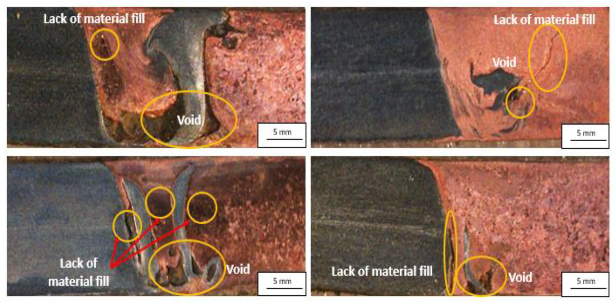
| Cu/316L SS | 5 | Butt | RPM: 720 Weld speed (mm/min): 16 Tool material: tool shoulder of Mo and pin of WC SD (mm): 22 Shielding gas: Ar Tool pin type: Cylindrical Pin Length (mm): 4.9 Pin diameter(mm): 5 | Tensile test Microstructure SEM Microhardness | UTS (MPa): 225.6 JE (%): 85 VHN: 290 Hv | [117] |
| Cu/316L SS | 2 | Butt | RPM: 1000, 1500 Weld speed (mm/min): 100, 200, 300, 350, 450, 550 Tool pin penetration (SS side) (mm): 0, 0.6, 1.6 Tool material: WC-14 Co Shoulder (convex) (mm): 25 Pin length (mm): 1.35 Maximum pin diameter(mm): 5.5 Tool pin type: taper | Tensile test Microstructure Micro hardness | UTS (MPa): 267 JE((%): 87 VHN: 60–100 Hv Optimum condition RPM: 1000 Welding speed (mm/min): 300 Tool pin penetration (SS side) (mm): 0 | [116] |
| Cu/304L SS | 3 | Butt | RPM: 1000 Tool pin offset (mm): −0.6 (steel side), 0, 0.6, 0.9 Welding speed (mm/min) 14–112 Tool tilt angle: 1.5° Tool material: WC Tool pin length: NR Tool shoulder diameter (mm): 18 Tool pin diameter (mm): root is 5 and t is 3 Tool pin type: taper | Tensile test Microstructure Micro hardness | UTS (MPa): 171.3 at 1.5 mm/min strain rate JE (%): 69 % EL: 6.8 VHN: 300 Hv Optimum condition Welding speed (mm/min): 40 Tool pin offset (mm): 0.9 towards Cu side | [118] |
| Cu/304L SS | 2 | Butt | RPM: 1000 Tool pin offset (mm): 3 (Cu side) Welding speed (mm/min) 40 Tool tilt angle: NR Tool material: WC Tool pin length: NR Tool shoulder diameter (mm): 10 Tool pin diameter (mm): root is 4 and the t is 2 | Tensile test Microstructure Microhardness | UTS (MPa); 216 at 2 mm/min strain rate VHN: 250 Hv | [164] |
| Cu/304L SS | 3 | Butt | RPM: 700, 760, 950, 1170, 1450 Tool pin offset (mm): 1 (SS side) Welding speed (mm/min) 25,31.5,40,50,60 Tool tilt angle (°): 1, 1.3, 1.8, 2.3, 2.6 Tool material: Shoulder is of M2 tool steel and pin is of WC Tool pin length: 2.5 Tool shoulder diameter (mm): 22 Tool pin shape: trapezoidal Tool pin diameter (mm): root is 22 and t is 17 | Tensile test Microstructure Micro-hardness SEM-EDS | UTS (MPa): 217.2 at 1 mm/min strain rate JE (%): 79 % EL: 20.7 VHN: 250 Optimum condition RPM: 950 Welding speed (mm/min): 40 Tool tilt angle(°): 1.8 | [120] |
| Cu/DSS | 4 | Butt | RPM: 1000,1200,1400 Tool pin offset (mm) (Cu side): 0,0.5,1 Tool plunge depth (mm): 0.1 Welding speed (mm/min) 20,30 Tool tilt angle (°): 3 Tool material: WC Tool pin length (mm): 4 Tool shoulder diameter (mm): 20 Tool pin diameter (mm): root is 5 and t is 3 | Tensile test Microstructure Micro-hardness SEM-EDS XRD | UTS (MPa): 279 at 1 × 10⁻³ s−1 strain rate JE (%): 96 VHN: 280 Optimum condition RPM: 1200 Weld speed (mm/min): 30 Tool pin offset (Cu side) (mm): 0.5 | [114,115] |
| CuCrZr/316LSS | 6/3 | Lap | RPM: 850 Tool plunge depth (mm): 0.5 Welding speed (mm/min) 50 Tool tilt angle (°): 2.5 Tool material: WC-25 Re Tool pin length (mm): 4 Tool shoulder diameter (mm): 16 Tool pin shape: taper spiral Tool pin diameter (mm): root is 7.5, and the t is 6 | Tensile test Lap shear testing Microstructure Micro-hardness SEM-EDS XRD | UTS (MPa): 305 %El: 50 Shear test peak load: 19 KN Shear extension (mm): 1.2 | [121] |
| 110 Cu/316 SS | 6 | Butt | RPM: 400, 500 Weld speed (mm/min): 25, 50 Tool pin offset (mm): 2 (Cu side) Tool tilt angle (°): 2.5 Tool material: W-Re Tool shoulder diameter (mm): 16 Tool pin diameter (mm): root is 7 and t is 5 Pin length (mm): 4 | Tensile test Microstructure SEM EDX | UTS (MPa): 225 JE (%): 100 VHN: around 375 Optimum condition RPM: 400 Weld speed (mm/min); 50 | [122] |
| C71000/304 SS | 2 | Butt | RPM: 800, 1000 Weld speed (mm/min): 40, 60, 80 Tool pin offset (mm): 0.75 (Cu side) Tool tilt angle (°): 2.5 Tool material: WC Tool shoulder diameter (mm): 18 Tool pin diameter (mm): 6 Tool pin type: Cylindrical Pin length (mm): 1.8 | Tensile test Microstructure SEM EDX XRD | UTS (MPa): 285 %El; 21 JE (%): 84 VHN: around 173 | [119] |
Publisher’s Note: MDPI stays neutral with regard to jurisdictional claims in published maps and institutional affiliations. |
© 2022 by the authors. Licensee MDPI, Basel, Switzerland. This article is an open access article distributed under the terms and conditions of the Creative Commons Attribution (CC BY) license (https://creativecommons.org/licenses/by/4.0/).
Share and Cite
Joshi, G.R.; Badheka, V.J.; Darji, R.S.; Oza, A.D.; Pathak, V.J.; Burduhos-Nergis, D.D.; Burduhos-Nergis, D.P.; Narwade, G.; Thirunavukarasu, G. The Joining of Copper to Stainless Steel by Solid-State Welding Processes: A Review. Materials 2022, 15, 7234. https://doi.org/10.3390/ma15207234
Joshi GR, Badheka VJ, Darji RS, Oza AD, Pathak VJ, Burduhos-Nergis DD, Burduhos-Nergis DP, Narwade G, Thirunavukarasu G. The Joining of Copper to Stainless Steel by Solid-State Welding Processes: A Review. Materials. 2022; 15(20):7234. https://doi.org/10.3390/ma15207234
Chicago/Turabian StyleJoshi, Gaurang R., Vishvesh J. Badheka, Raghavendra S. Darji, Ankit D. Oza, Vivek J. Pathak, Dumitru Doru Burduhos-Nergis, Diana Petronela Burduhos-Nergis, Gautam Narwade, and Gopinath Thirunavukarasu. 2022. "The Joining of Copper to Stainless Steel by Solid-State Welding Processes: A Review" Materials 15, no. 20: 7234. https://doi.org/10.3390/ma15207234