
Microstructure and Mechanical Properties of AZ91 Rein-Forced with High Volume Fraction of Oriented Short Carbon Fibers

 ,
,  ,
, 
 ,
, 
Abstract
:1. Introduction
2. Methodology
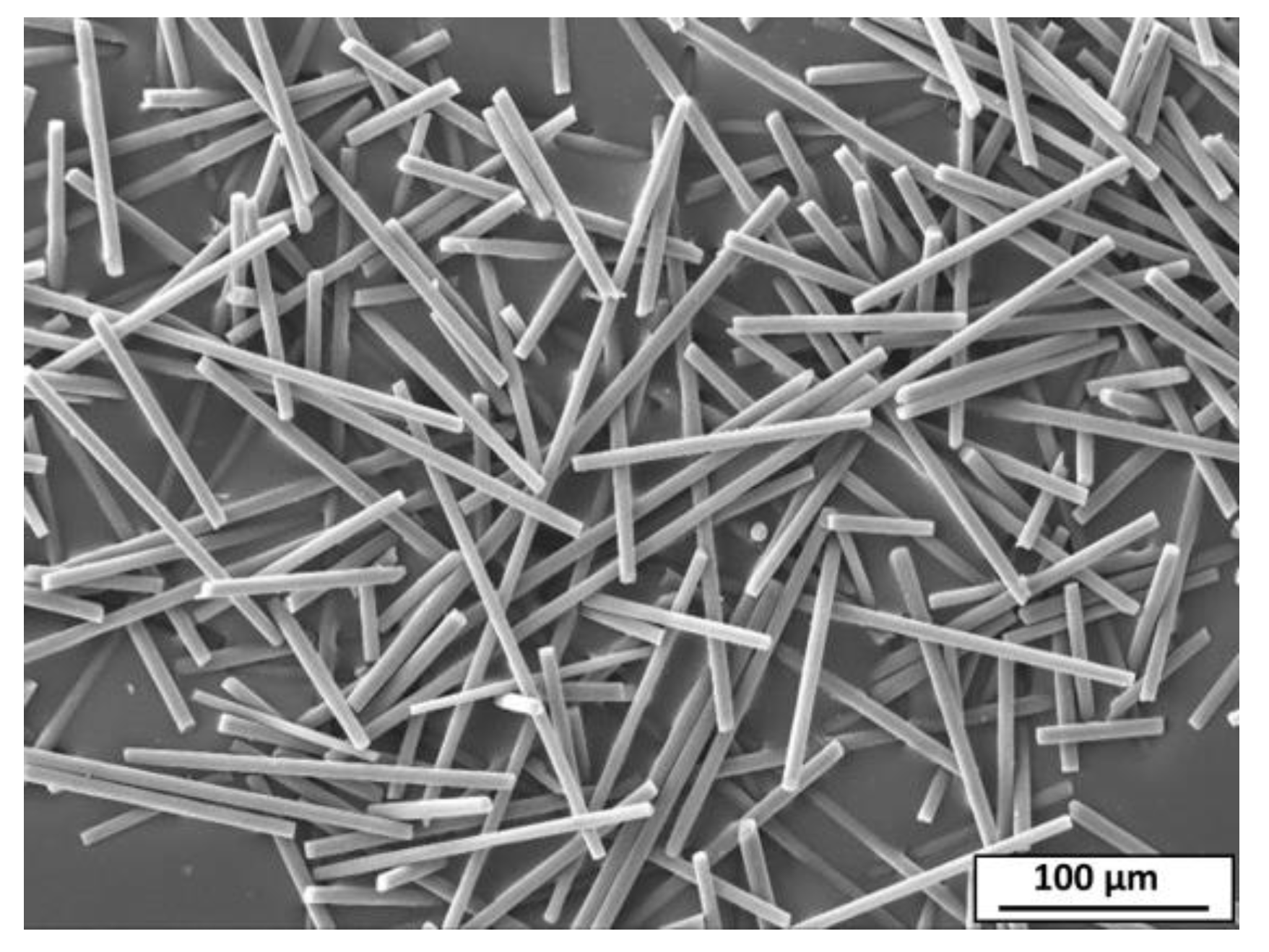
2.1. Materials
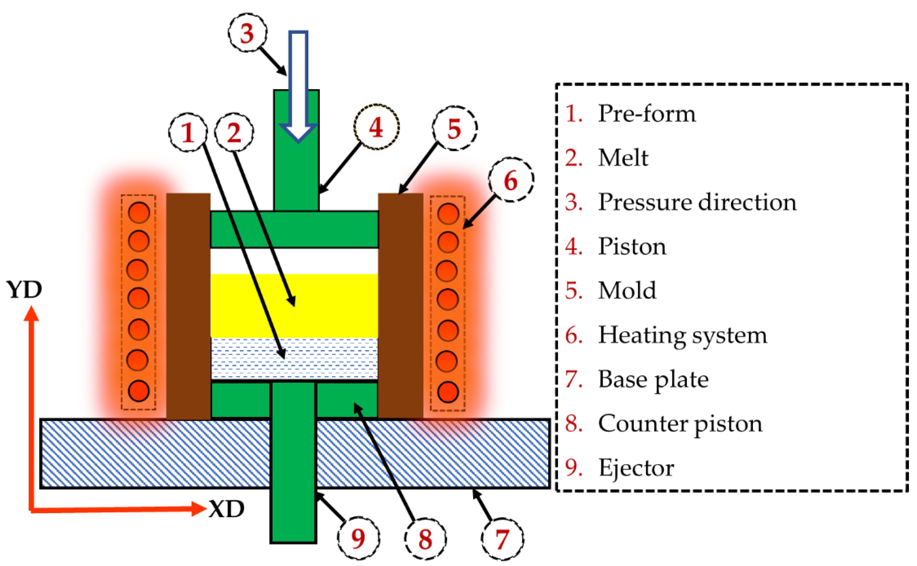
2.2. Production of AZ91/Carbon Fiber Composite
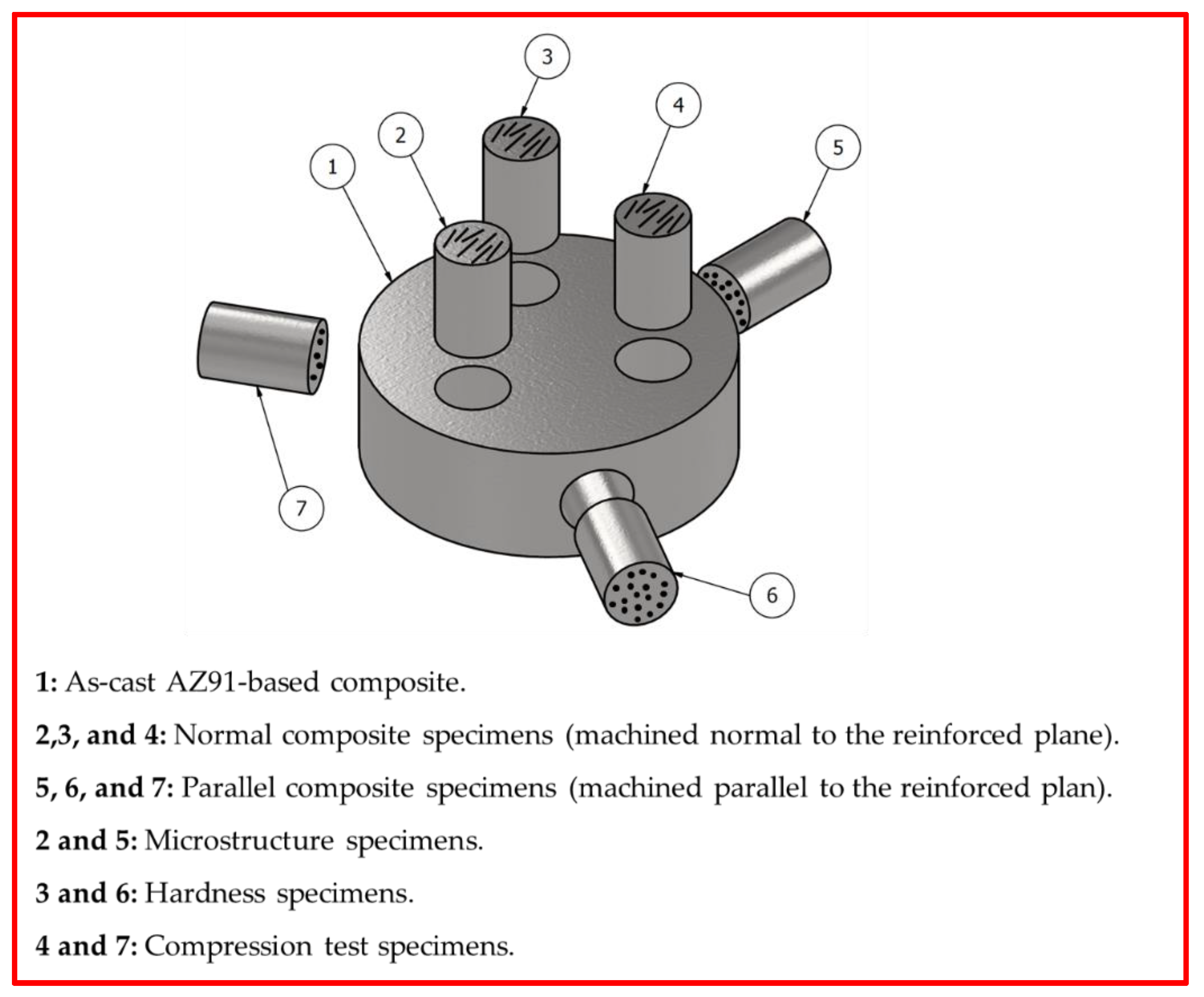
2.3. Characterization of the Produced Composite
3. Results and Discussion
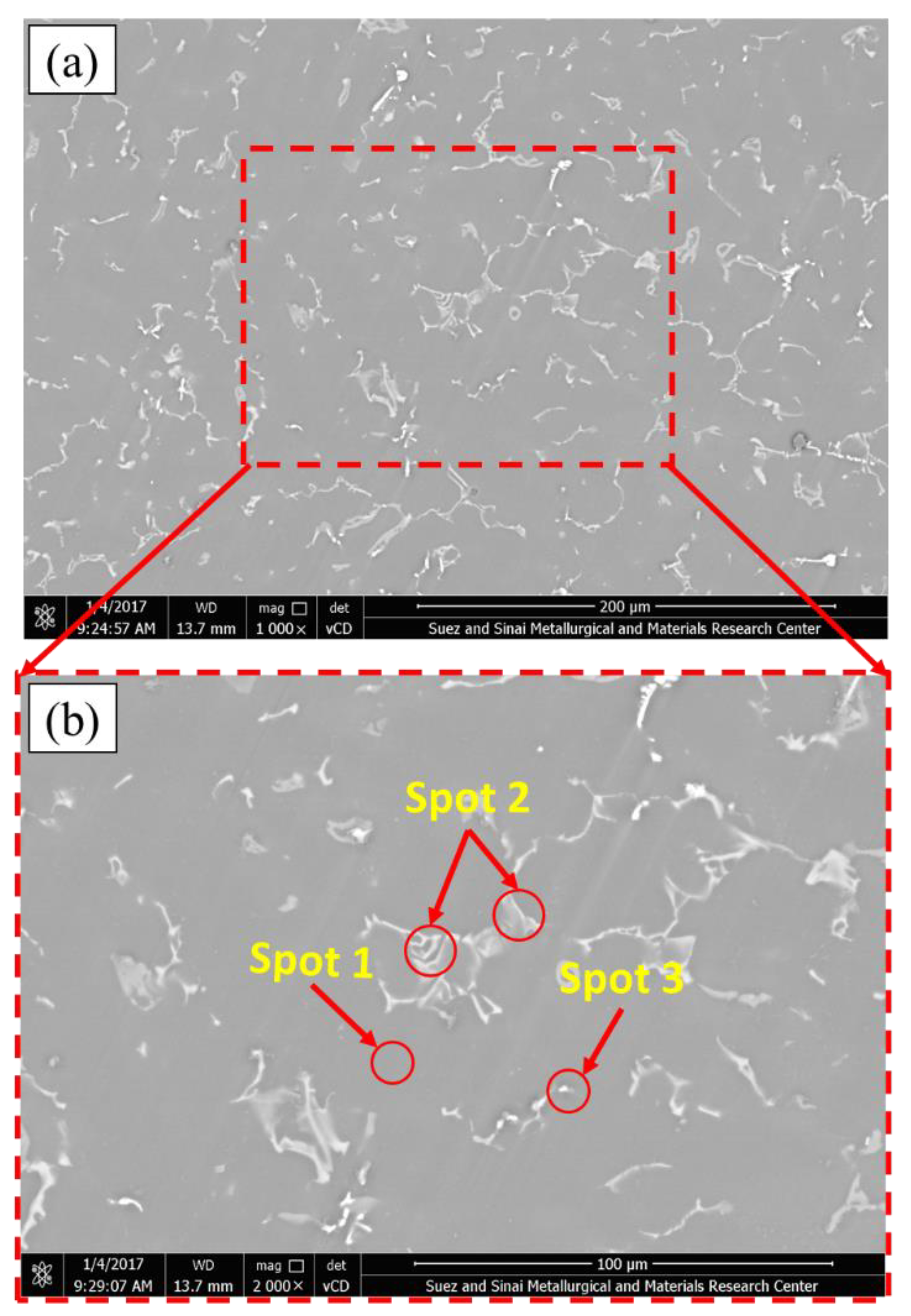
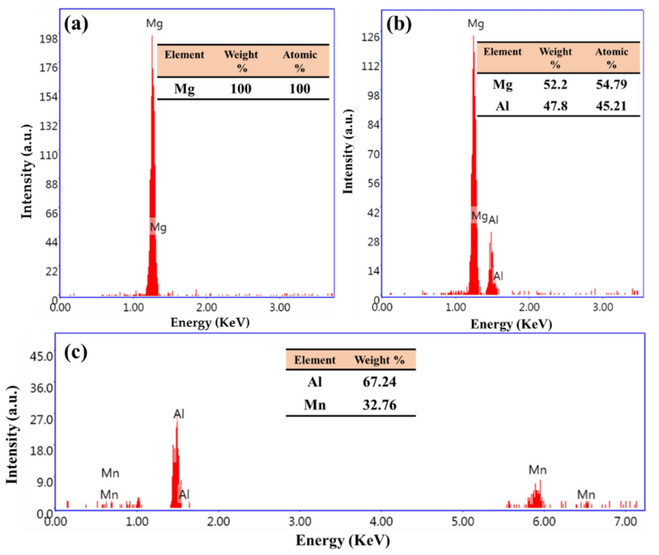
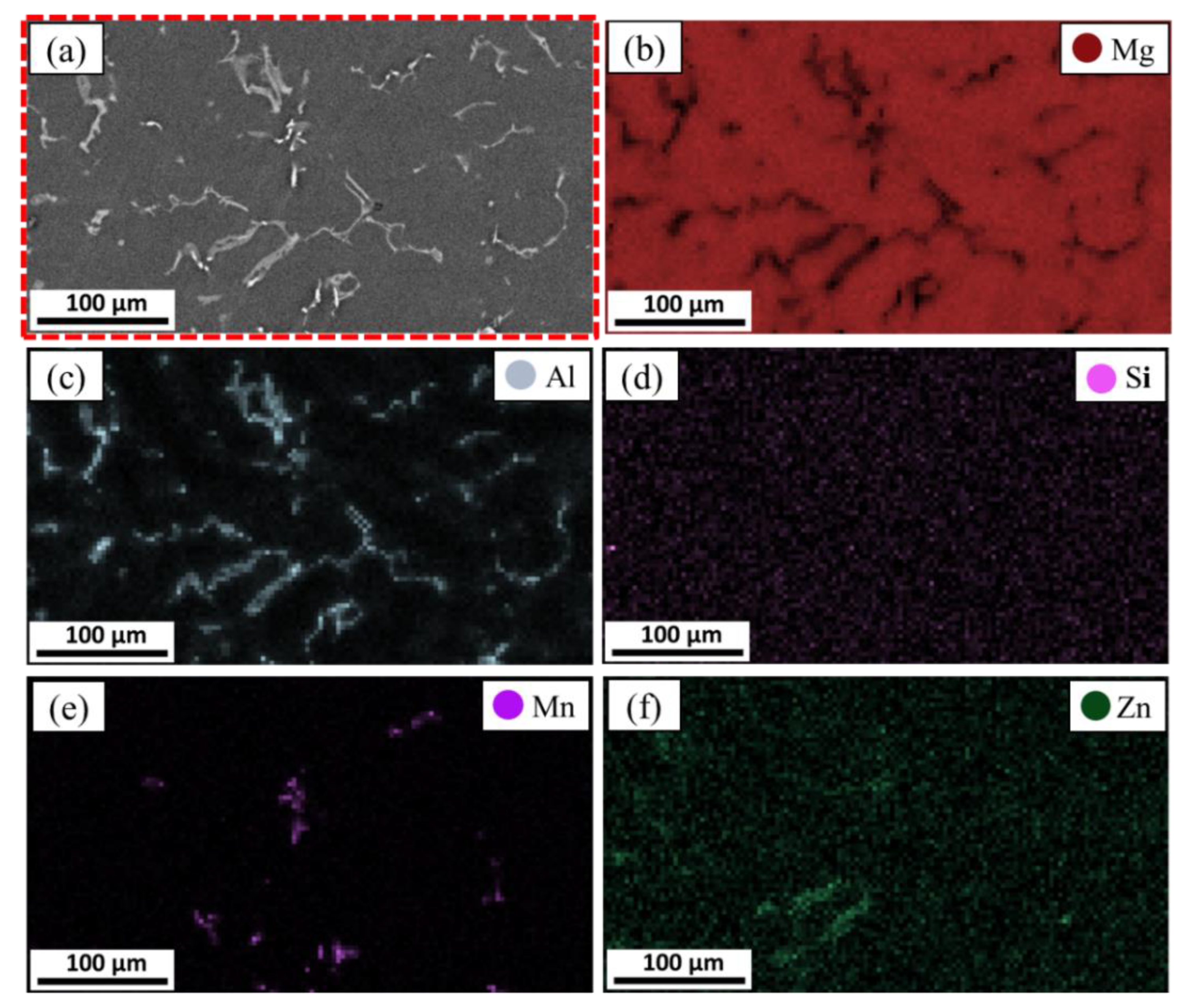
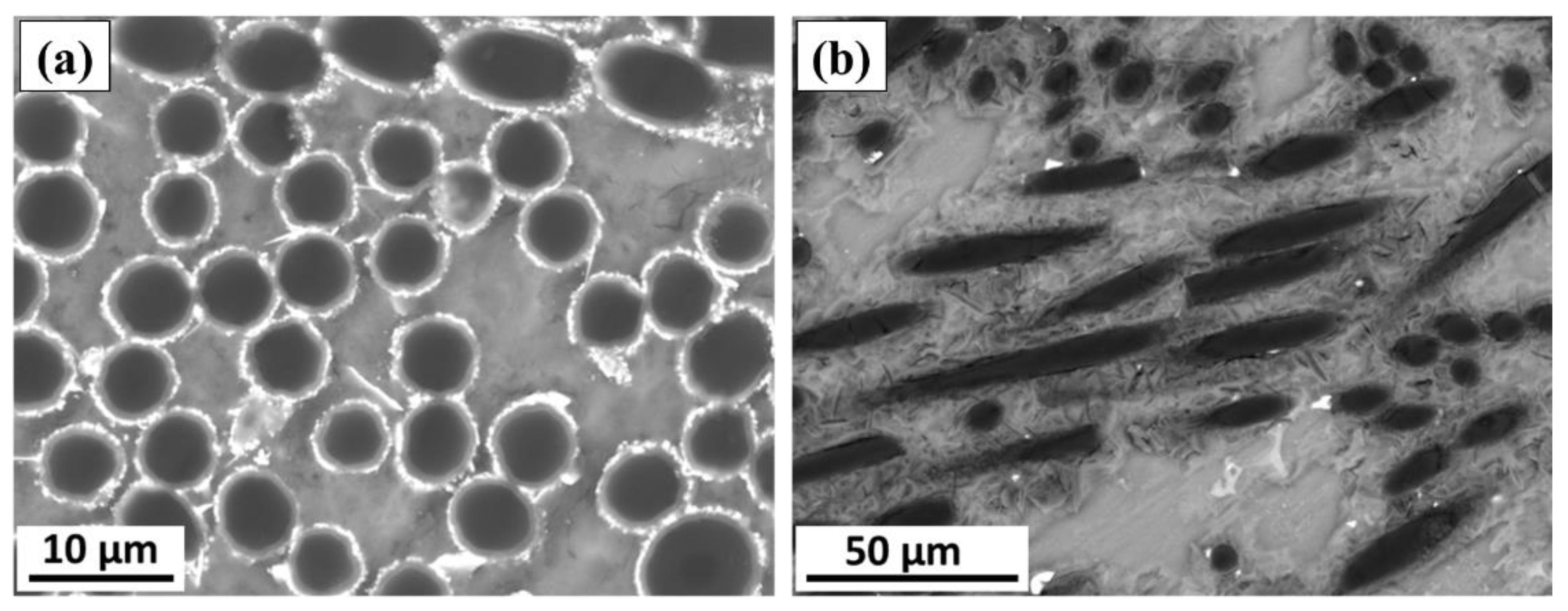
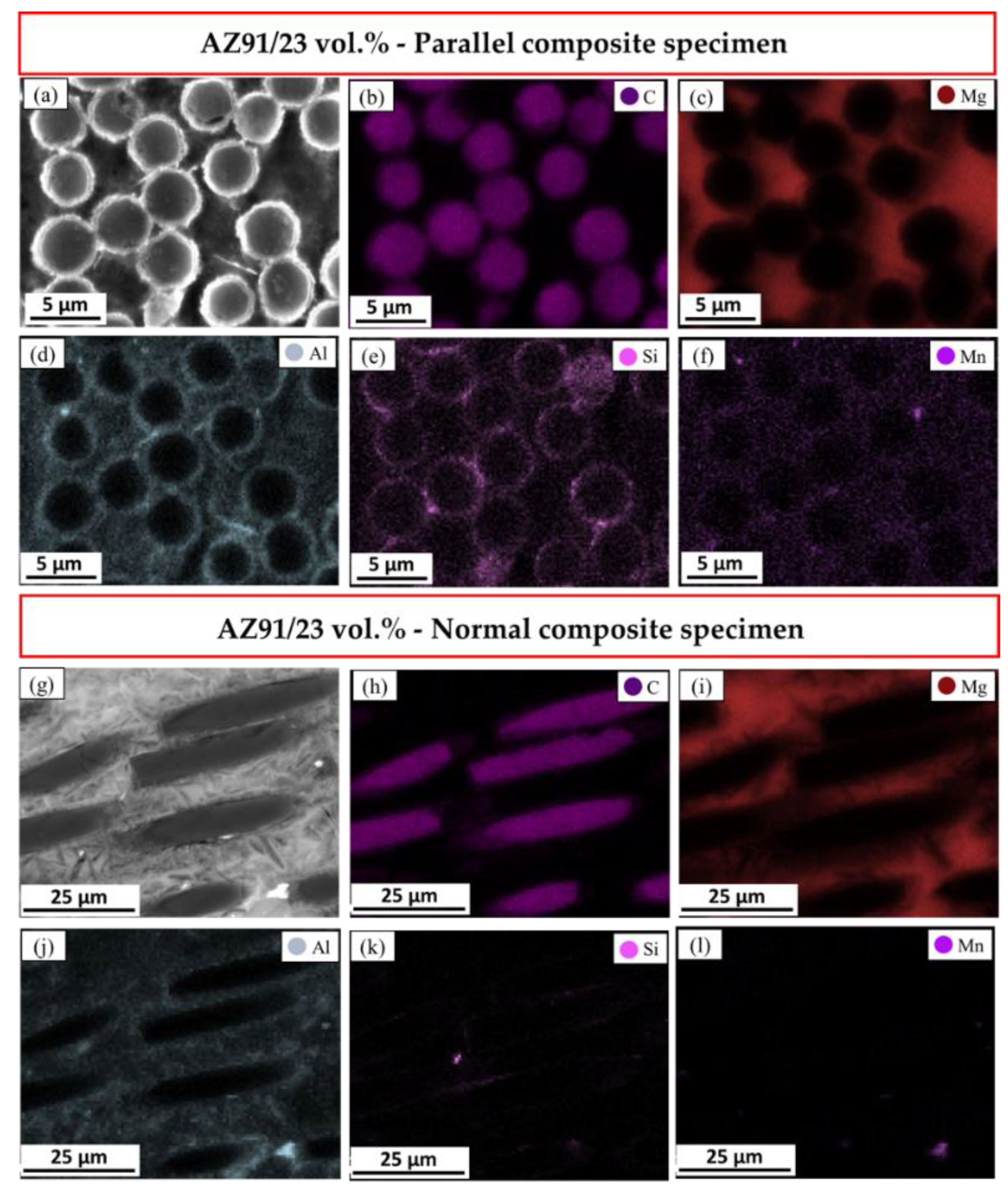
3.1. Microstructure Analysis
3.2. Physical and Mechanical Properties
4. Conclusions
- The squeeze casting process successfully produced a highly dense AZ91-based composite containing a high-volume fraction of carbon short fibers (23%), which bonded well with the matrix and highly distributed in the normal and parallel direction to the reinforcing plane.
- Reinforcing AZ91 with 23 vol.% short carbon fibers increases the hardness of the AZ91 matrix by not less than 51% for the parallel and normal composite specimens.
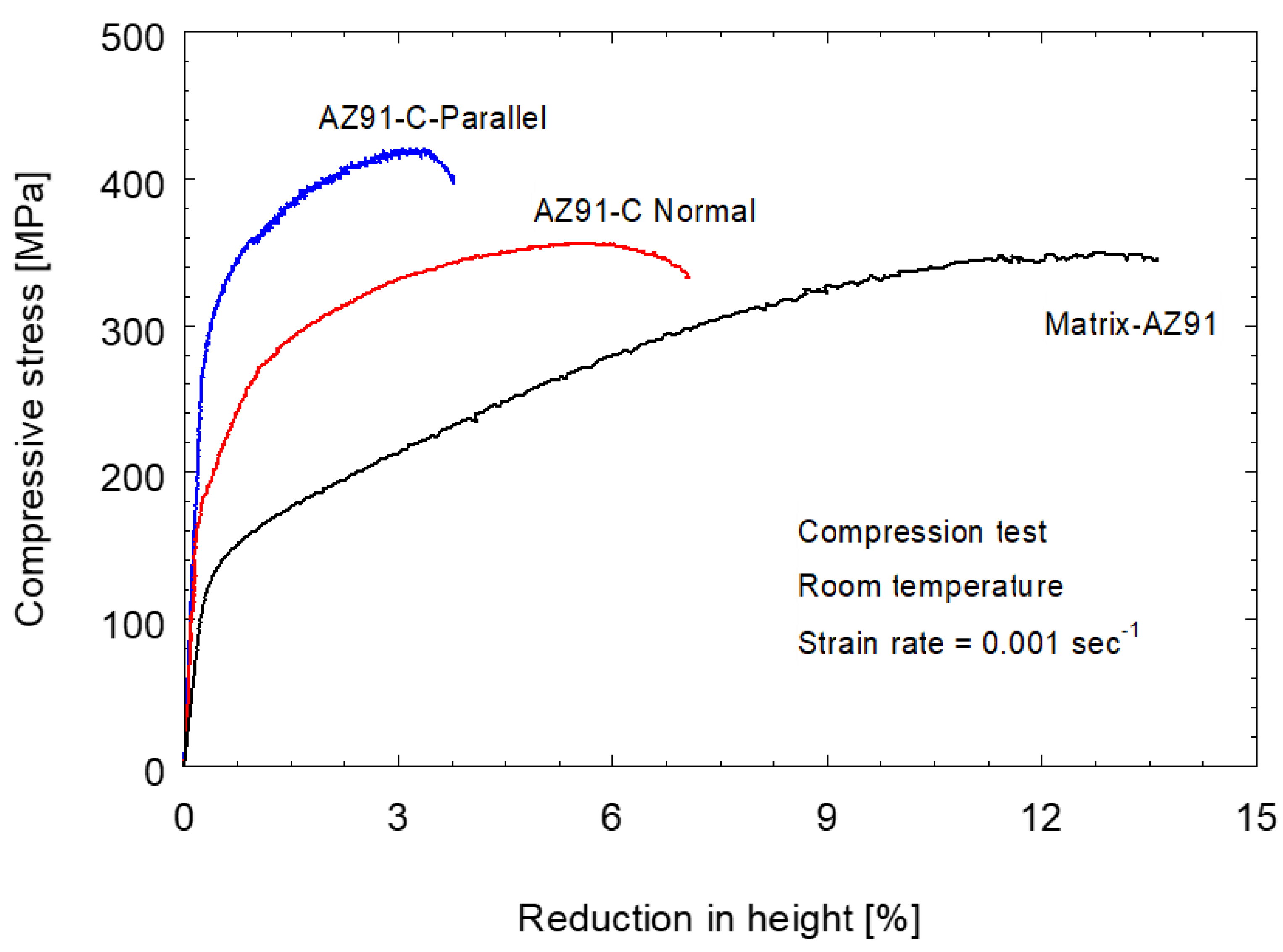
- The yield compressive strength and the ultimate compressive strength of the composite are higher than those recorded for the AZ91 matrix. Moreover, the parallel fiber composite specimen gives the highest yield compressive strength (311 MPa) and ultimate compressive strength (419 MPa), compared to the normal fiber composite specimen and the AZ91 matrix alloy.
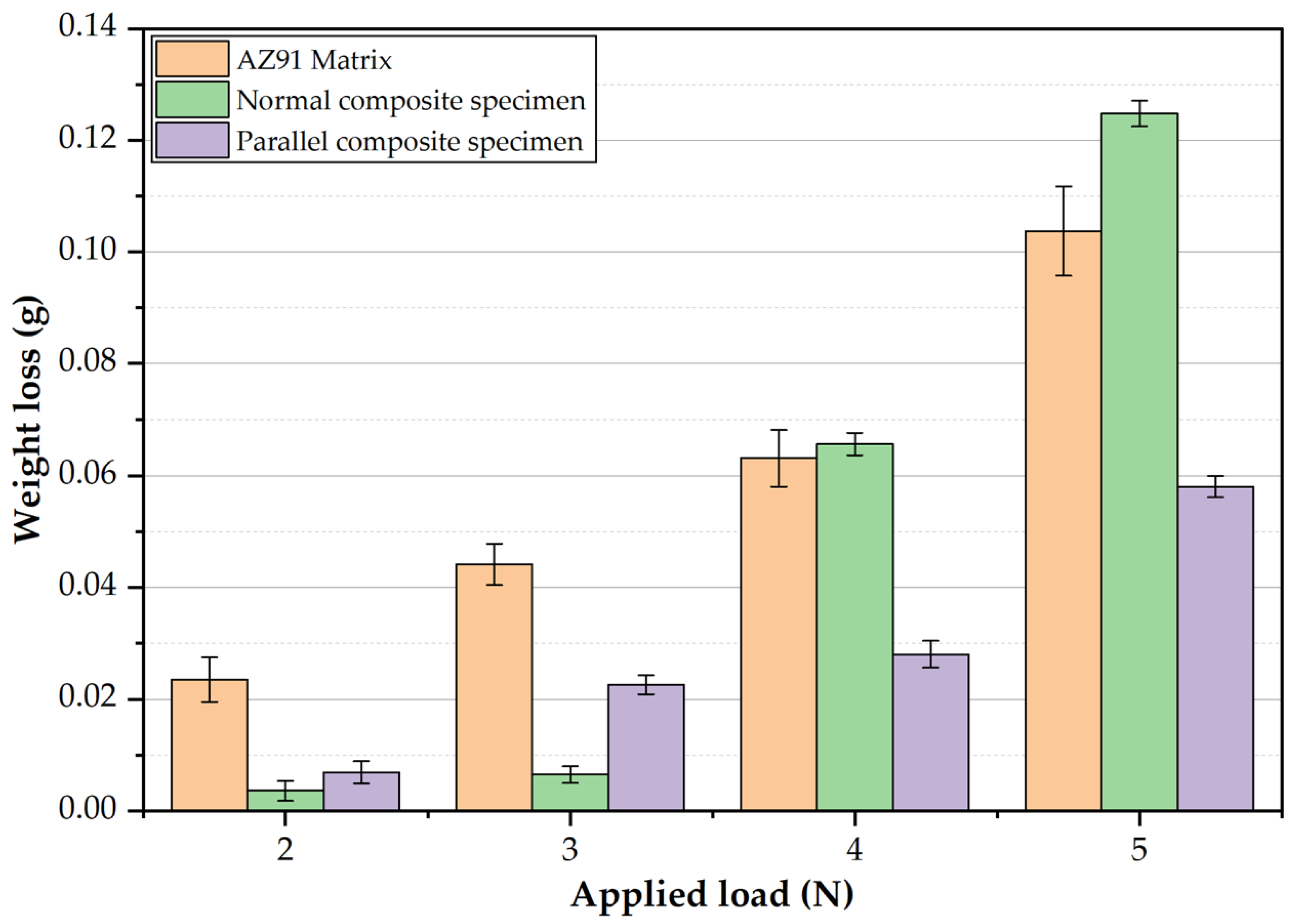
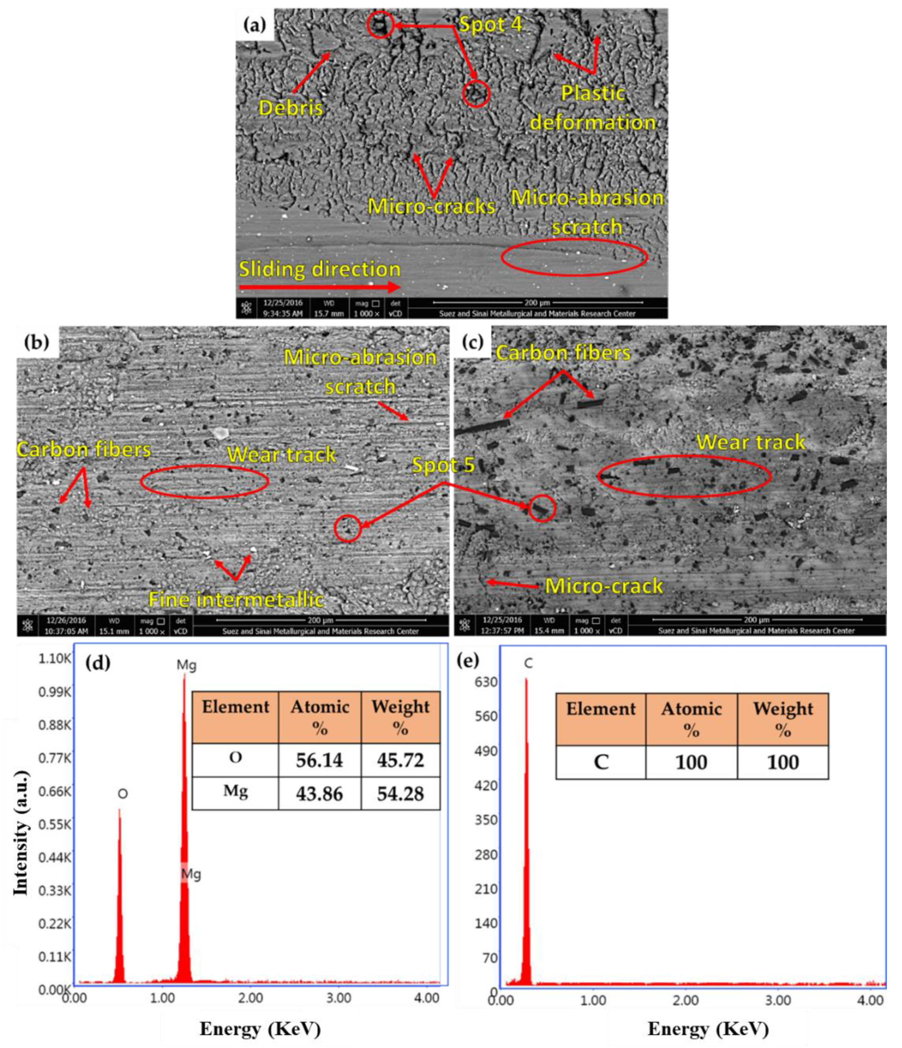
- At the constant sliding distance of 2.3 × 106 cm and applied wear loads of 2 and 3 N, the composite specimens (parallel and normal specimens) show a significant improvement in wear resistance over the AZ91 matrix alloy. Additionally, at the wear loads of 4 and 5 N, the parallel composite specimen shows a remarked enhancement in wear resistance compared to the AZ91 matrix and the normal composite specimen.
Author Contributions
Funding
Institutional Review Board Statement
Informed Consent Statement
Data Availability Statement
Acknowledgments
Conflicts of Interest
References
- Nie, K.B.; Wang, X.J.; Deng, K.K.; Hu, X.S.; Wu, K. Magnesium matrix composite reinforced by nanoparticles—A review. J. Magnes. Alloy. 2021, 9, 57–77. [Google Scholar] [CrossRef]
- Ataya, S.; Alsaleh, N.A.; El-Sayed Seleman, M.M. Strength and wear behavior of Mg Alloy AE42 reinforced with carbon short fibers. Acta Metall. Sin. (Engl. Lett.) 2019, 32, 31–40. [Google Scholar] [CrossRef] [Green Version]
- Mohanavel, V.; Vijay, K.; Vigneswaran, A.; Srinath, S.; Gokulnath, S. Mechanical and tribological behaviour of AZ91/ZrSiO4 composites. Mater. Today Proc. 2020, 37, 1529–1534. [Google Scholar] [CrossRef]
- Ataya, S.; Mielke, S.; El-Magd, E. Creep behavior of Mg-Alloys AE42 and AZ91 reinforced with carbon short fibers. In Magnesium: Proceedings of the 6th International Conference Magnesium Alloys and Their Applications; John Wiley & Sons: Hoboken, NJ, USA, 2005; pp. 384–389. [Google Scholar] [CrossRef]
- Ataya, S.; El-Magd, E. Quasi-static behavior of Mg-alloys with and without short-fiber reinforcement. Theor. Appl. Fract. Mech. 2007, 47, 102–112. [Google Scholar] [CrossRef]
- Seleman, M.M.E.; Ataya, S.; Ahmed, M.M.Z.; Hassan, A.M.M.; Latief, F.H.; Hajlaoui, K.; El-Nikhaily, A.E.; Habba, M.I.A. The additive manufacturing of aluminum matrix nano Al2O3 composites produced via friction stir deposition using different initial material conditions. Materials 2022, 15, 2926. [Google Scholar] [CrossRef] [PubMed]
- Hoziefa, W.; Toschi, S.; Ahmed, M.M.Z.; Morri, A.; Mahdy, A.A.; El-Sayed Seleman, M.M.; El-Mahallawi, I.; Ceschini, L.; Atlam, A. Influence of friction stir processing on the microstructure and mechanical properties of a compocast AA2024-Al2O3 nanocomposite. Mater. Des. 2016, 106, 273–284. [Google Scholar] [CrossRef]
- Bakkar, A.; Ahmed, M.M.Z.; Alsaleh, N.A.; Seleman, M.M.E.S.; Ataya, S. Microstructure, wear, and corrosion characterization of high TiC content inconel 625 matrix composites. J. Mater. Res. Technol. 2019, 8, 1102–1110. [Google Scholar] [CrossRef]
- Aydin, F.; Sun, Y.; Emre Turan, M. The effect of TiB2 content on wear and mechanical behavior of AZ91 magnesium matrix composites produced by powder metallurgy. Powder Metall. Met. Ceram. 2019, 57, 564–572. [Google Scholar] [CrossRef]
- Yang, L.; Hou, H.; Zhao, Y.; Yang, X. Microstructure and mechanical properties of squeeze casting quasicrystal reinforced AZ91D magnesium matrix composites. Xiyou Jinshu Cailiao Yu Gongcheng/Rare Met. Mater. Eng. 2016, 45, 1978–1982. [Google Scholar] [CrossRef] [Green Version]
- Turan, M.E.; Sun, Y.; Aydin, F.; Zengin, H.; Turen, Y.; Ahlatci, H. Effects of carbonaceous reinforcements on microstructure and corrosion properties of magnesium matrix composites. Mater. Chem. Phys. 2018, 218, 182–188. [Google Scholar] [CrossRef]
- Parande, G.; Manakari, V.; Sharma Kopparthy, S.D.; Gupta, M. A Study on the Effect of Low-Cost Eggshell Reinforcement on the Immersion, Damping and Mechanical Properties of Magnesium–Zinc Alloy; Elsevier Ltd.: Amsterdam, The Netherlands, 2020; Volume 182, ISBN 6565166358. [Google Scholar]
- Sahoo, S.K.; Sahoo, B.N.; Panigrahi, S.K. Effect of in-situ sub-micron sized TiB2 reinforcement on microstructure and mechanical properties in ZE41 magnesium matrix composites. Mater. Sci. Eng. A 2020, 773, 138883. [Google Scholar] [CrossRef]
- Wang, X.J.; Hu, X.S.; Wu, K.; Deng, K.K.; Gan, W.M.; Wang, C.Y.; Zheng, M.Y. Hot deformation behavior of SiCp/AZ91 magnesium matrix composite fabricated by stir casting. Mater. Sci. Eng. A 2008, 492, 481–485. [Google Scholar] [CrossRef]
- Hu, M.; Wei, S.; Shi, Q.; Ji, Z.; Xu, H.; Wang, Y. Dynamic recrystallization behavior and mechanical properties of bimodal scale Al2O3 reinforced AZ31 composites by soild state synthesis. J. Magnes. Alloy. 2020, 8, 841–848. [Google Scholar] [CrossRef]
- Sahoo, B.N.; Panigrahi, S.K. Synthesis, characterization and mechanical properties of in-situ (TiC-TiB2) reinforced magnesium matrix composite. Mater. Des. 2016, 109, 300–313. [Google Scholar] [CrossRef]
- Zhang, X.; Zhang, Q.; Hu, H. tensile behaviour and microstructure of magnesium AM60-based hybrid composite containing Al2O3 fibres and particles. Mater. Sci. Eng. A 2014, 607, 269–276. [Google Scholar] [CrossRef]
- Kandemir, S.; Gavras, S.; Dieringa, H. High temperature tensile, compression and creep behavior of recycled short carbon fibre reinforced AZ91 magnesium alloy fabricated by a high shearing dispersion technique. J. Magnes. Alloy. 2021, 9, 1753–1767. [Google Scholar] [CrossRef]
- Tian, J.; Shi, Z.Q. Creep mechanism and creep constitutive model of aluminum silicate short-fiber-reinforced magnesium matrix composite. Trans. Nonferrous Met. Soc. China (Engl. Ed.) 2014, 24, 632–640. [Google Scholar] [CrossRef]
- Qi, L.; Guan, J.; Liu, J.; Zhou, J.; Wei, X. Wear behaviors of Cf/Mg composites fabricated by extrusion directly following vacuum pressure infiltration technique. Wear 2013, 307, 127–133. [Google Scholar] [CrossRef]
- Xu, H.; Yang, Z.; Hu, M.; Ji, Z. Effect of short carbon fiber content on SCFs/AZ31 composite microstructure and mechanical properties. Results Phys. 2020, 17, 103074. [Google Scholar] [CrossRef]
- Li, S.; Qi, L.; Zhang, T.; Zhou, J.; Li, H. Microstructure and tensile behavior of 2D-Cf/AZ91D composites fabricated by liquid–solid extrusion and vacuum pressure infiltration. J. Mater. Sci. Technol. 2017, 33, 541–546. [Google Scholar] [CrossRef]
- Feldhoff, A.; Pippel, E.; Woltersdorf, J. Carbon-fibre reinforced magnesium alloys: Nanostructure and chemistry of interlayers and their effect on mechanical properties. J. Microsc. 1999, 196, 185–193. [Google Scholar] [CrossRef] [PubMed]
- Li, S.S.; Tang, B.; Zeng, D. Ben effects and mechanism of ca on refinement of AZ91D alloy. J. Alloys Compd. 2007, 437, 317–321. [Google Scholar] [CrossRef]
- Torabi Parizi, M.; Ebrahimi, G.R.; Ezatpour, H.R. Effect of graphene nanoplatelets content on the microstructural and mechanical properties of AZ80 magnesium alloy. Mater. Sci. Eng. A 2019, 742, 373–389. [Google Scholar] [CrossRef]
- Wang, Y.; Liu, G.; Fan, Z. Microstructural evolution of rheo-diecast AZ91D magnesium alloy during heat treatment. Acta Mater. 2006, 54, 689–699. [Google Scholar] [CrossRef]
- Srinivasan, A.; Swaminathan, J.; Gunjan, M.K.; Pillai, U.T.S.; Pai, B.C. Effect of intermetallic phases on the creep behavior of AZ91 magnesium alloy. Mater. Sci. Eng. A 2010, 527, 1395–1403. [Google Scholar] [CrossRef]
- Afsharnaderi, A.; Malekan, M.; Emamy, M.; Rasizadeh Ghani, J.; Lotfpour, M. Microstructure evolution and mechanical properties of the AZ91 magnesium alloy with Sr and Ti additions in the as-cast and as-aged conditions. J. Mater. Eng. Perform. 2019, 28, 6853–6863. [Google Scholar] [CrossRef]
- Li, Y.; Chen, Y.; Cui, H.; Xiong, B.; Zhang, J. Microstructure and mechanical properties of spray-formed AZ91 magnesium alloy. Mater. Charact. 2009, 60, 240–245. [Google Scholar] [CrossRef]
- Bonnah, R.C.; Fu, Y.; Hao, H. Microstructure and mechanical properties of AZ91 magnesium alloy with minor additions of Sm, Si and Ca elements. China Foundry 2019, 16, 319–325. [Google Scholar] [CrossRef] [Green Version]
- Anilan Ajukumar, K.; AjithKumar, K.K.; Kunjayyappan Ravikumar, K.; Deva Rajan, T.P.; Subramonia Pillai, U.T.; Chandrasekhara Pai, B. Fabrication and characterization of short carbon fiber reinforced AZ91 Mg alloy composites. Mater. Sci. Forum 2012, 710, 347–352. [Google Scholar] [CrossRef]
- Olszówka-Myalska, A.; Myalski, J. Magnesium alloy AZ31—Short carbon fiber composite obtained by pressure die casting. Solid State Phenom. 2015, 229, 115–122. [Google Scholar] [CrossRef]
- Turan, M.E.; Aydin, F. Improved elevated temperature mechanical properties of graphene-reinforced pure aluminium matrix composites. Mater. Sci. Technol. 2020, 36, 1092–1103. [Google Scholar] [CrossRef]
- Chen, L.Y.; Konishi, H.; Fehrenbacher, A.; Ma, C.; Xu, J.Q.; Choi, H.; Xu, H.F.; Pfefferkorn, F.E.; Li, X.C. Novel nanoprocessing route for bulk graphene nanoplatelets reinforced metal matrix nanocomposites. Scr. Mater. 2012, 67, 29–32. [Google Scholar] [CrossRef]
- Satish, K.G.; Siddeswarappa, B.; Kaleemulla, K.M. Characterization of in-plane mechanical properties of laminated hybrid composites. J. Miner. Mater. Charact. Eng. 2010, 09, 105–114. [Google Scholar] [CrossRef]
- Tian, W.; Qi, L.; Zhou, J.; Guan, J. Effects of the fiber orientation and fiber aspect ratio on the tensile strength of Csf/Mg composites. Comput. Mater. Sci. 2014, 89, 6–11. [Google Scholar] [CrossRef]
- Mortazavian, S.; Fatemi, A. Effects of fiber orientation and anisotropy on tensile strength and elastic modulus of short fiber reinforced polymer composites. Compos. Part B Eng. 2015, 72, 116–129. [Google Scholar] [CrossRef]
- Seleman, M.M.E.S.; Ahmed, M.M.; Ataya, S. Microstructure and Mechanical Properties of Hot Extruded 6016 Aluminum Alloy/Graphite Composites. J. Mater. Sci. Technol. 2018, 34, 1580–1591. [Google Scholar] [CrossRef]
- Russell-Stevens, M.; Todd, R.; Papakyriacou, M. The effect of thermal cycling on the properties of a carbon fibre reinforced magnesium composite. Mater. Sci. Eng. A 2005, 397, 249–256. [Google Scholar] [CrossRef]
- Aydin, F.; Durgut, R. Estimation of wear performance of AZ91 alloy under dry sliding conditions using machine learning methods. Trans. Nonferrous Met. Soc. China (Engl. Ed.) 2021, 31, 125–137. [Google Scholar] [CrossRef]
- Aydin, F.; Turan, M.E. The effect of boron nitride on tribological behavior of Mg matrix composite at room and elevated temperatures. J. Tribol. 2019, 142, 011601. [Google Scholar] [CrossRef]


| Element | Mn | Si | Zn | Al | Mg |
|---|---|---|---|---|---|
| wt.% | 0.13 | 0.05 | 1.00 | 9.00 | Bal. |
| Chemical Composition | Tensile Strength | Elastic Modulus | Density |
|---|---|---|---|
| >95 wt.% C | 3.5 GPa | 280 GPa | 1.76 g/cm3 |
| Material | Bulk Density g/cm3 | Theoretical Density g/cm3 | Relative Density (%) | Hardness (HV) |
|---|---|---|---|---|
| AZ91 as-cast alloy | 1.8080 ± 0.003 | 1.8060 | 0.9989 | 70 ± 3 |
| Parallel composite specimen | 1.7950 ± 0.004 | 1.7768 | 0.9899 | 111 ± 2 |
| Normal composite specimen | 1.7800 ± 0.008 | 1.7602 | 0.9889 | 106 ± 4 |
| Material | UCS (MPa) | YCS (MPa) | R (%) |
|---|---|---|---|
| AZ91 as-cast alloy | 348 ± 9 | 139 ± 7 | 13.6 ± 1.2 |
| Parallel composite specimen | 419 ± 15 | 311 ± 12 | 3.8 ± 0.6 |
| Normal composite specimen | 356 ± 13 | 192 ± 10 | 7.1 ± 0.8 |
Publisher’s Note: MDPI stays neutral with regard to jurisdictional claims in published maps and institutional affiliations. |
© 2022 by the authors. Licensee MDPI, Basel, Switzerland. This article is an open access article distributed under the terms and conditions of the Creative Commons Attribution (CC BY) license (https://creativecommons.org/licenses/by/4.0/).
Share and Cite
Ataya, S.; El-Sayed Seleman, M.M.; Latief, F.H.; Ahmed, M.M.Z.; Hajlaoui, K.; Elshaghoul, Y.G.Y.; Habba, M.I.A. Microstructure and Mechanical Properties of AZ91 Rein-Forced with High Volume Fraction of Oriented Short Carbon Fibers. Materials 2022, 15, 4818. https://doi.org/10.3390/ma15144818
Ataya S, El-Sayed Seleman MM, Latief FH, Ahmed MMZ, Hajlaoui K, Elshaghoul YGY, Habba MIA. Microstructure and Mechanical Properties of AZ91 Rein-Forced with High Volume Fraction of Oriented Short Carbon Fibers. Materials. 2022; 15(14):4818. https://doi.org/10.3390/ma15144818
Chicago/Turabian StyleAtaya, Sabbah, Mohamed M. El-Sayed Seleman, Fahamsyah H. Latief, Mohamed M. Z. Ahmed, Khalil Hajlaoui, Yousef G. Y. Elshaghoul, and Mohamed I. A. Habba. 2022. "Microstructure and Mechanical Properties of AZ91 Rein-Forced with High Volume Fraction of Oriented Short Carbon Fibers" Materials 15, no. 14: 4818. https://doi.org/10.3390/ma15144818