
Numerical Analysis of Physical Characteristics and Heat Transfer Decoupling Behavior in Bypass Coupling Variable Polarity Plasma Arc

 , ,
, ,
Abstract
:
1. Introduction
2. Principle and Model of Heat Source
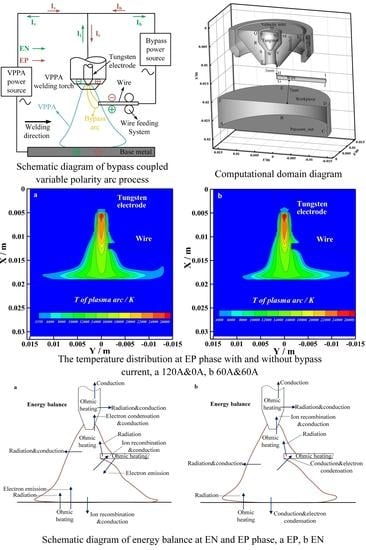
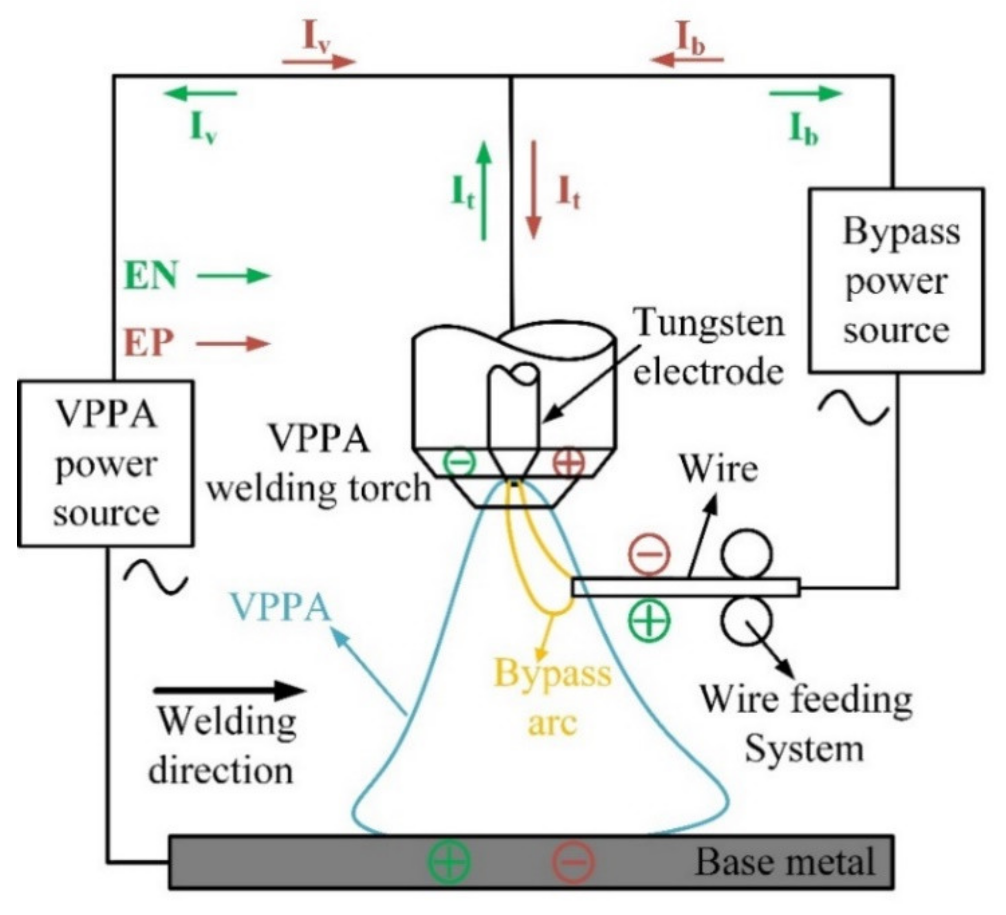
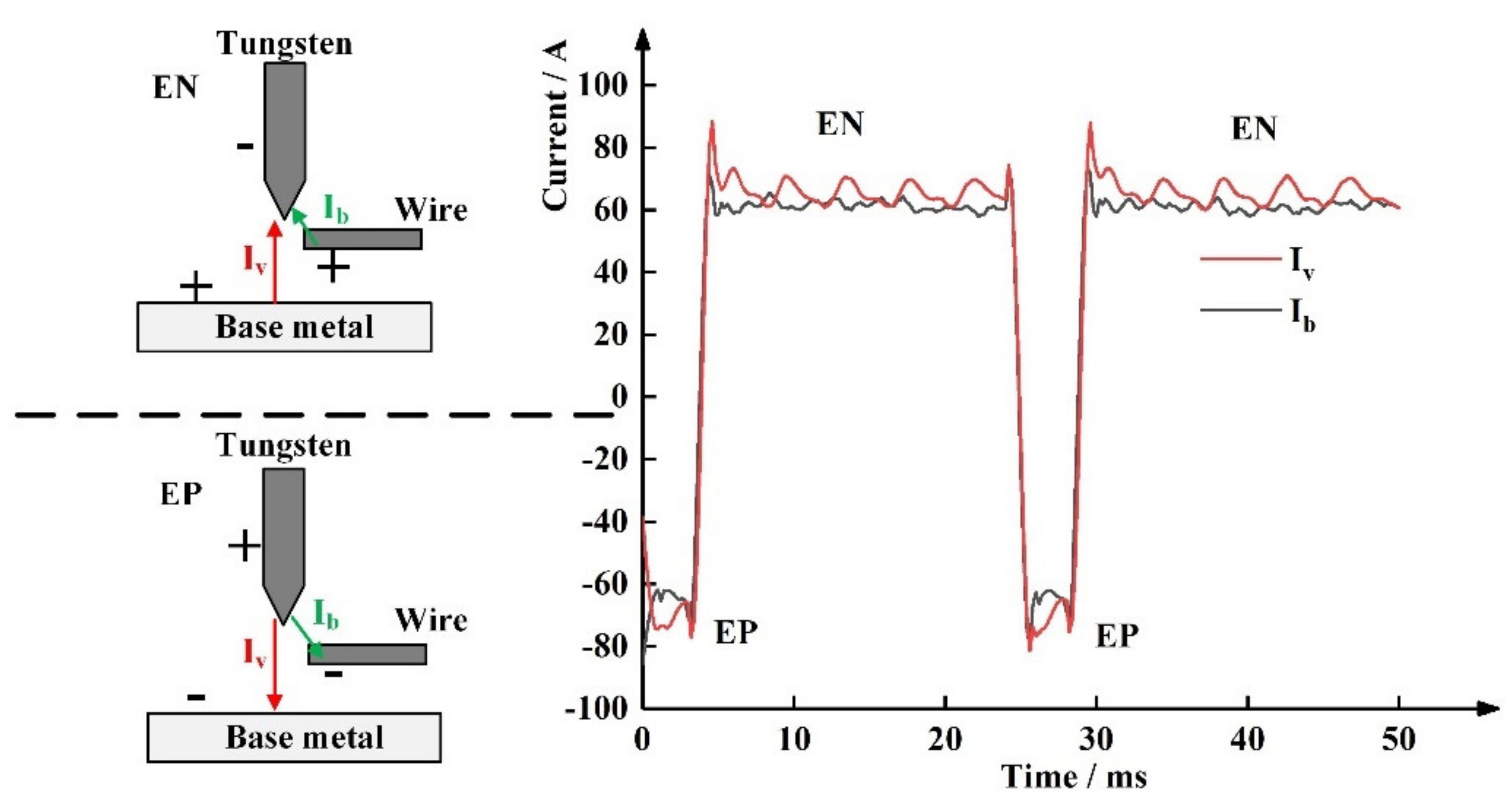
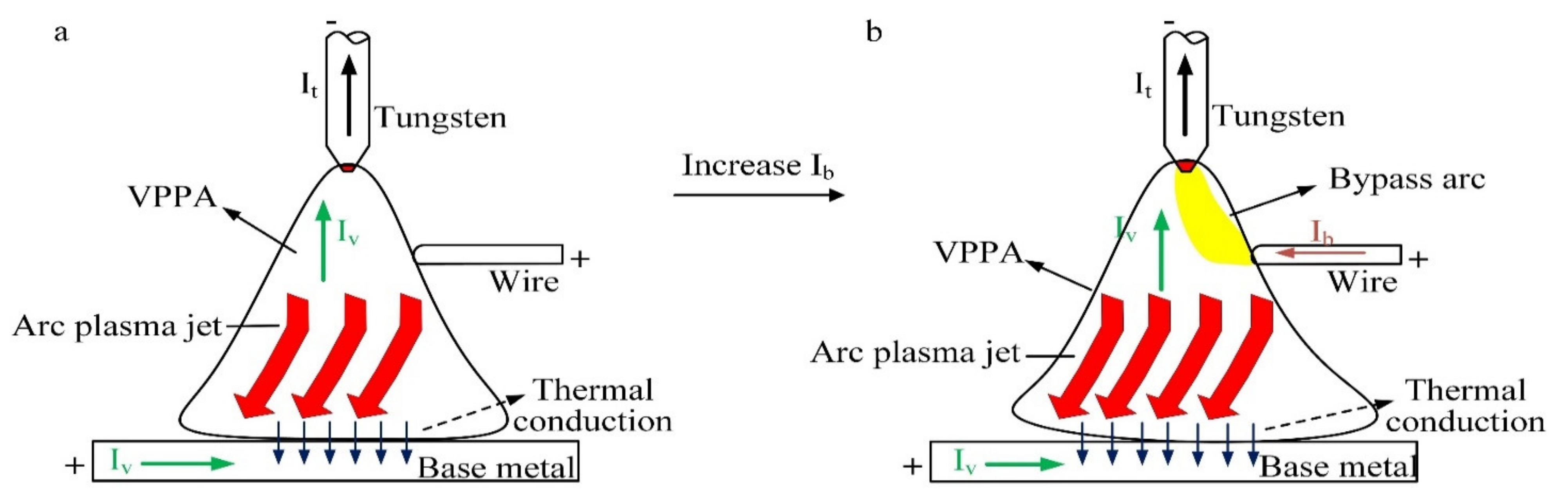
2.1. Principle of Heat Source
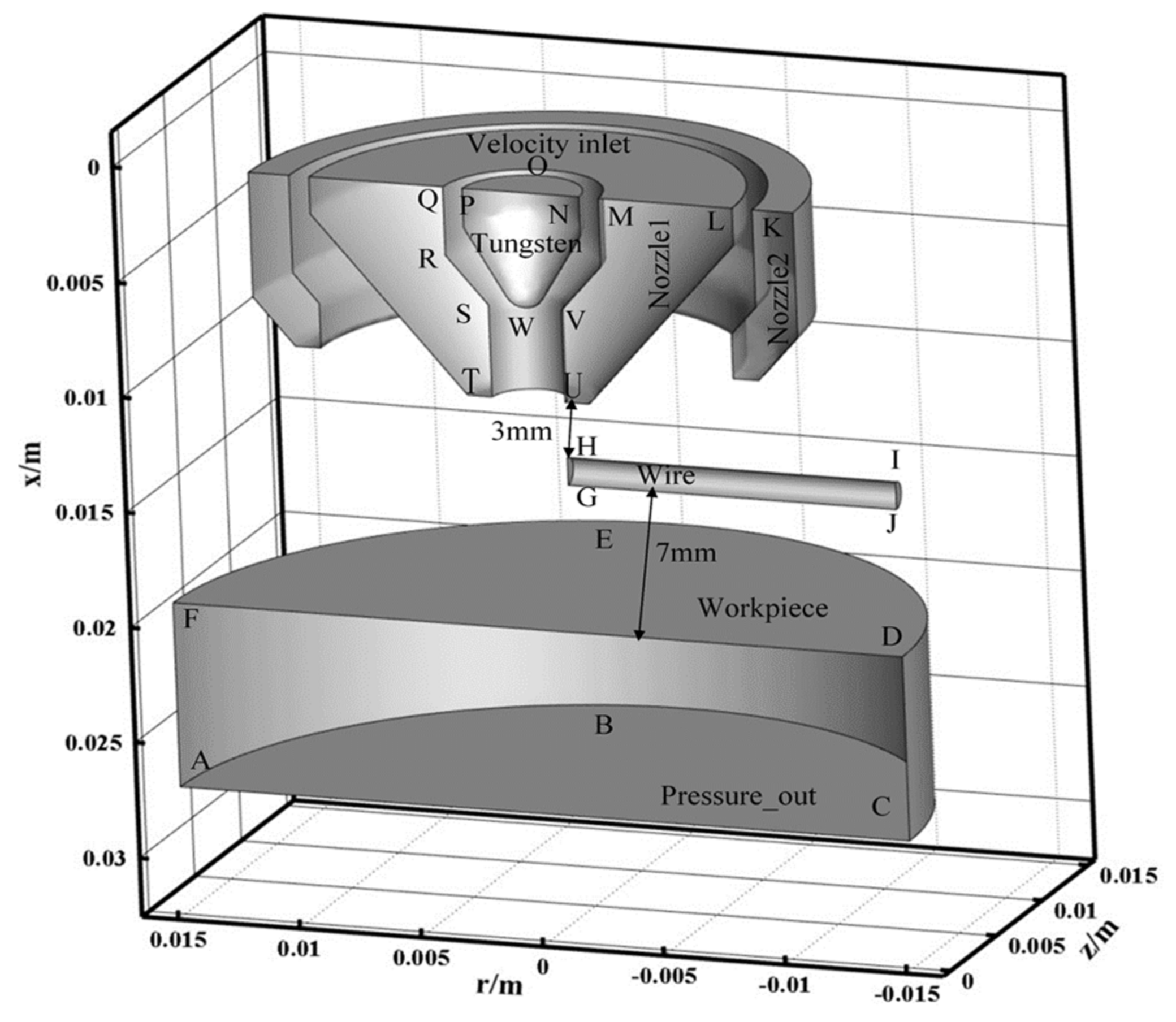
2.2. Calculated Domain
2.3. Simulation Conditions
2.4. Magnetic Fluid Dynamics Model
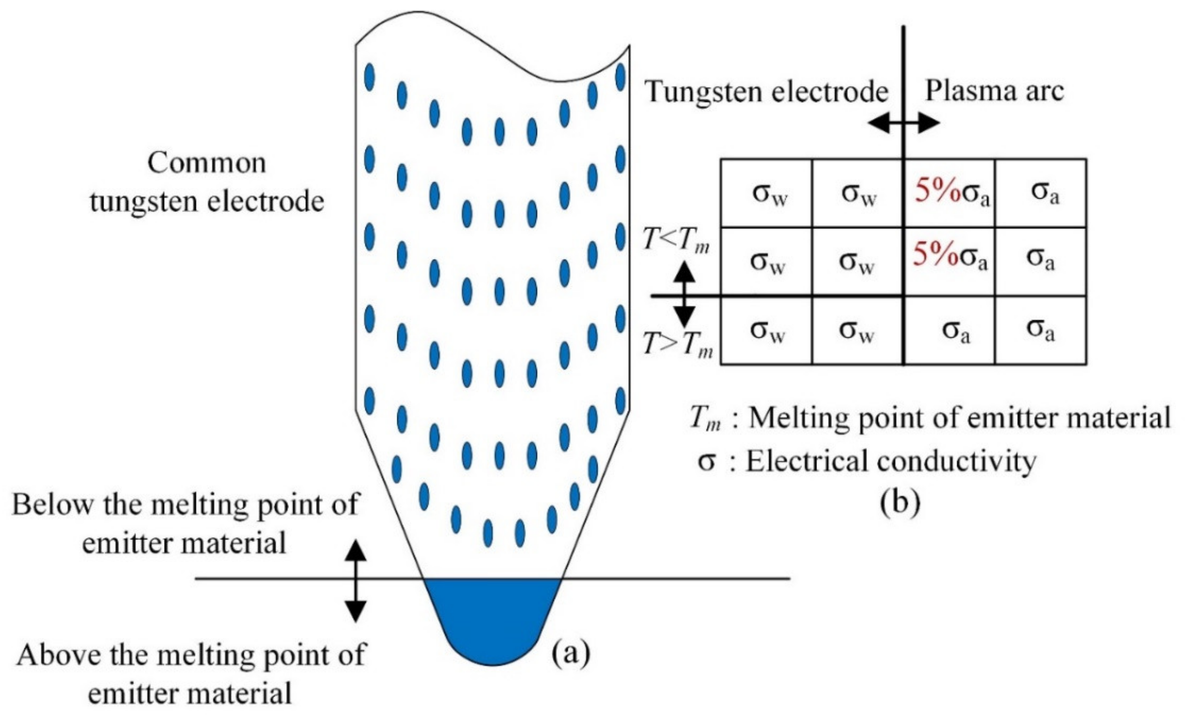
2.5. Model of Current Attachment on the Tungsten Electrode Surface
3. Results and Discussion
3.1. The Physics of Bypass Coupling Variable Polarity Plasma Arc
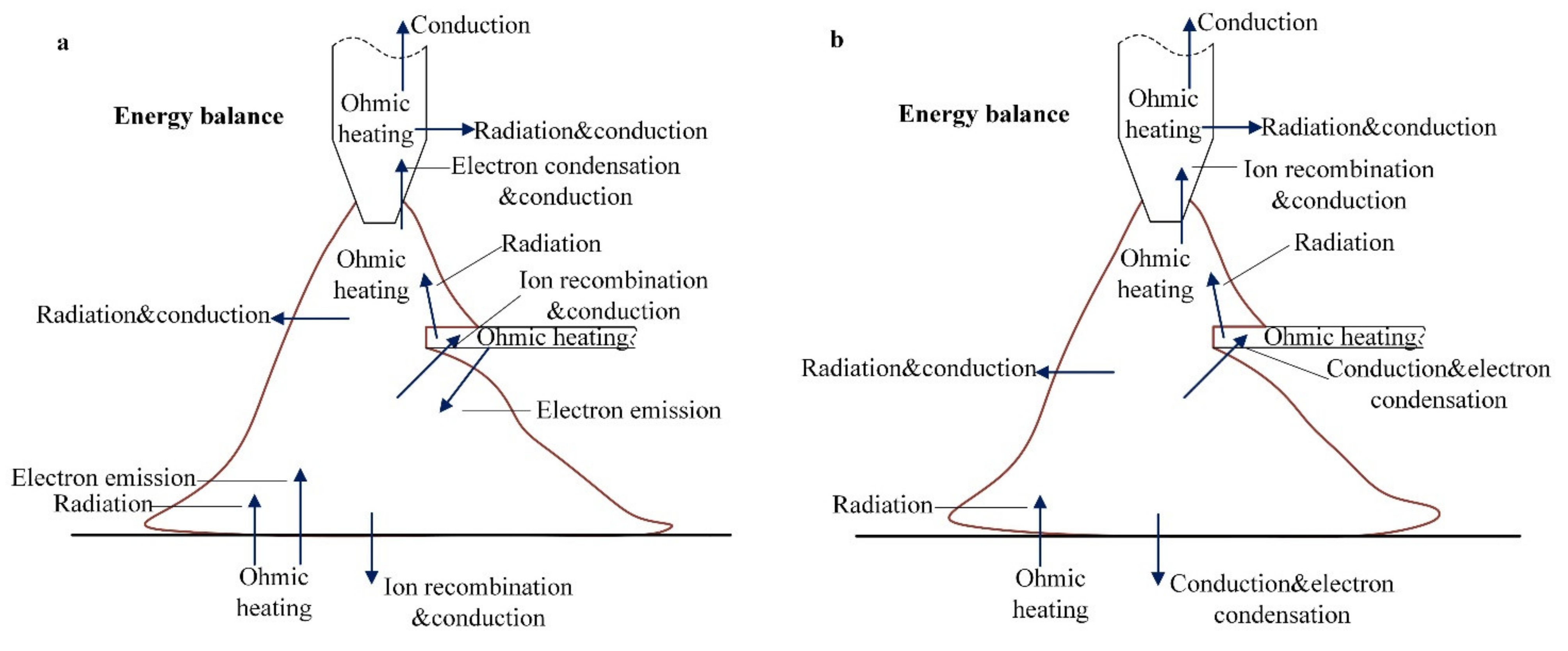
3.2. The Energy Transfer between Electrode and Coupling Arc
4. Conclusions
- (1)
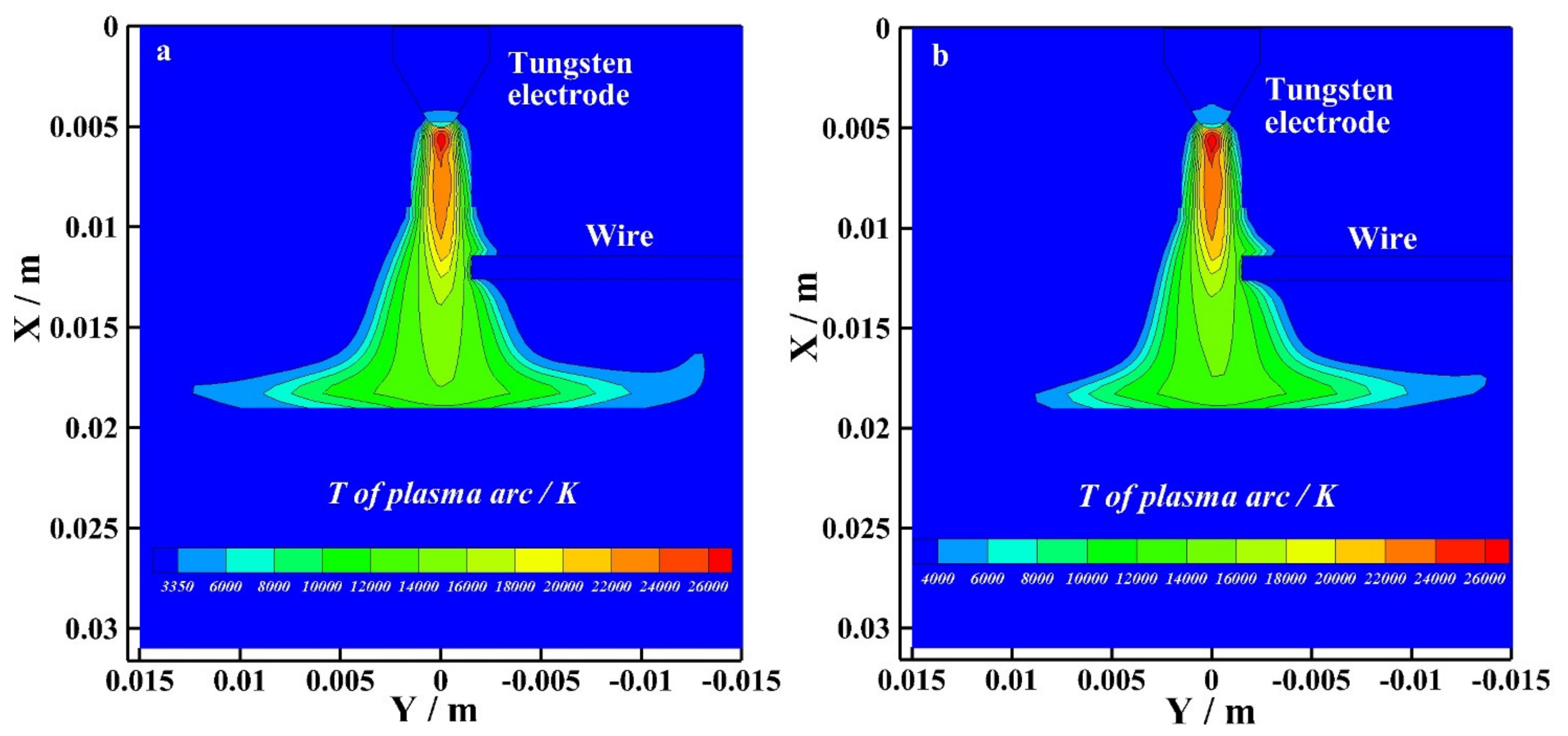
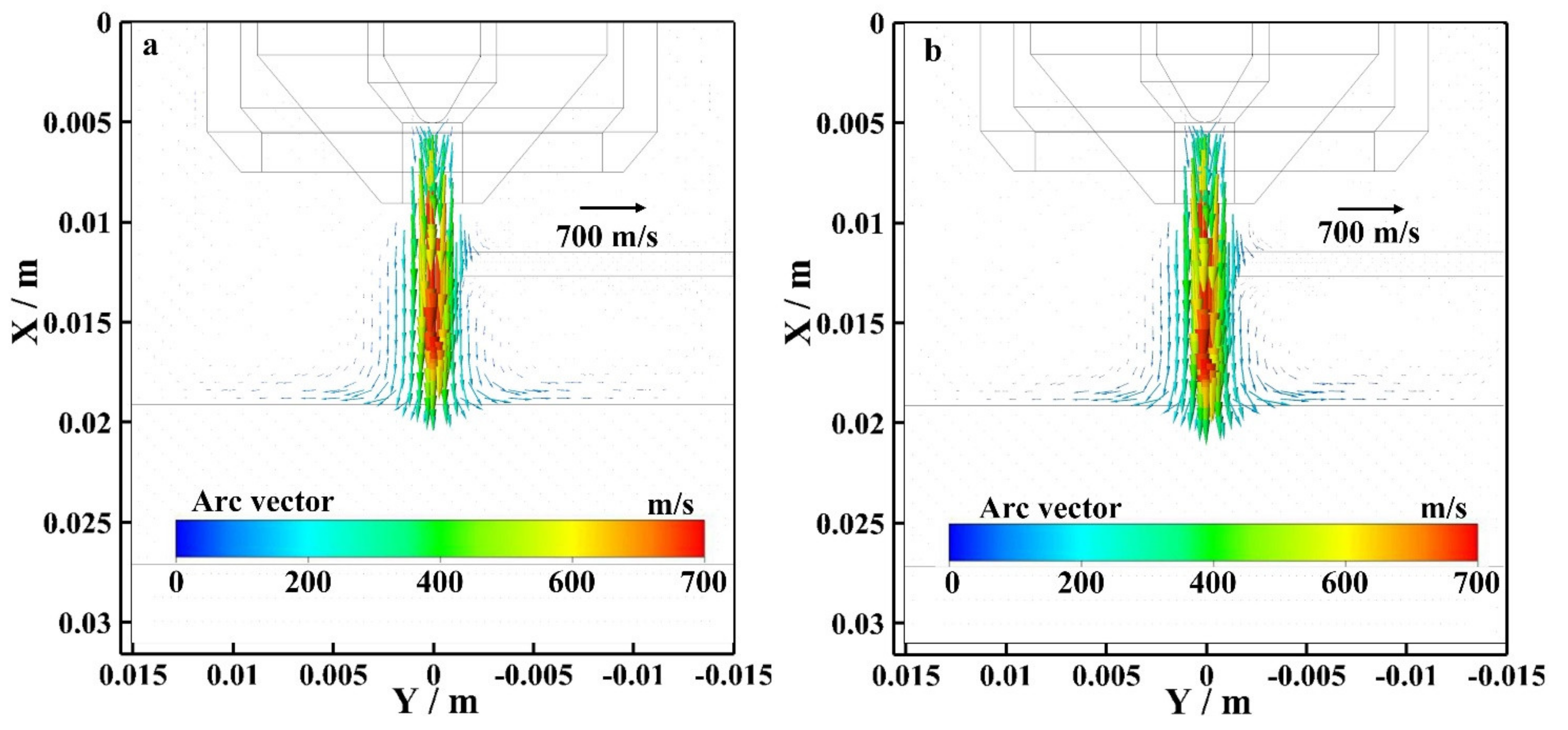
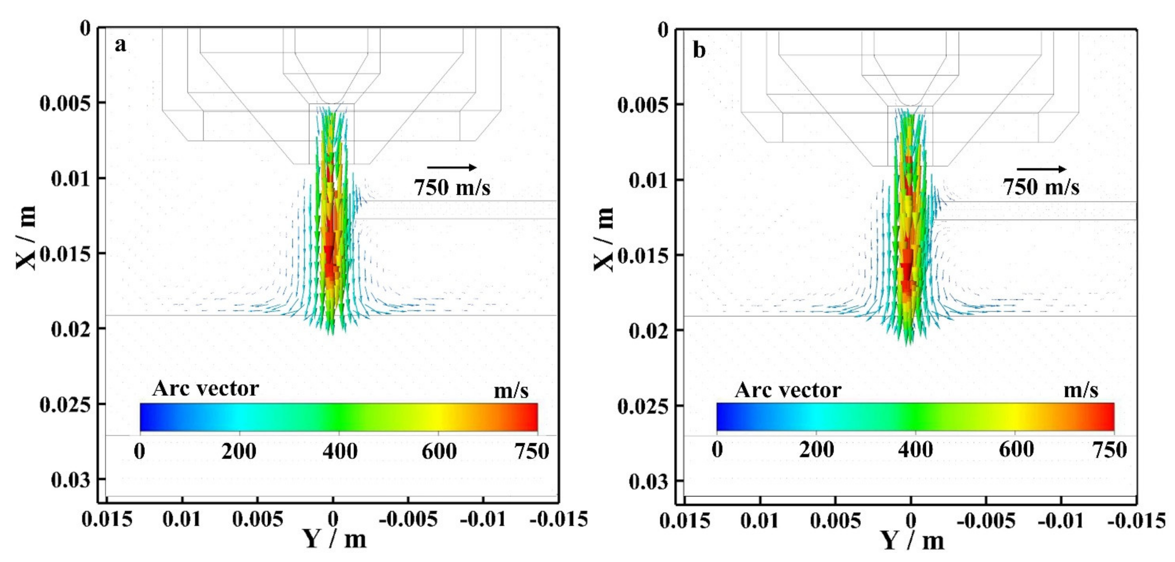
- The results show that the radius of the bypass coupling arc with or without bypass current action on the base metal is different, and the flow vector of the bypass coupling arc plasma with bypass current is larger than the arc without bypass current. The arc physics affect the heat transfer between the arc and base metal;
- (2)
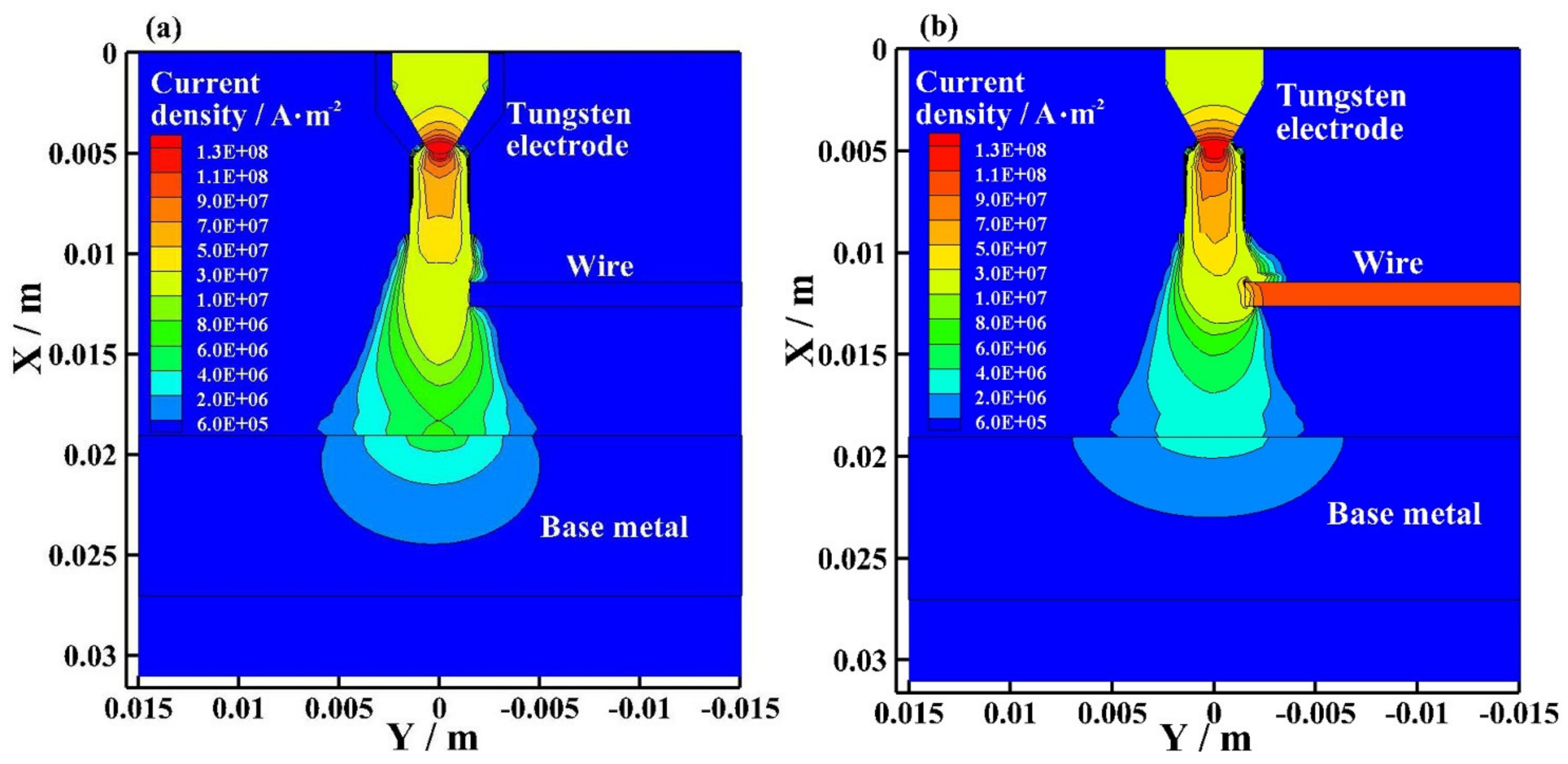
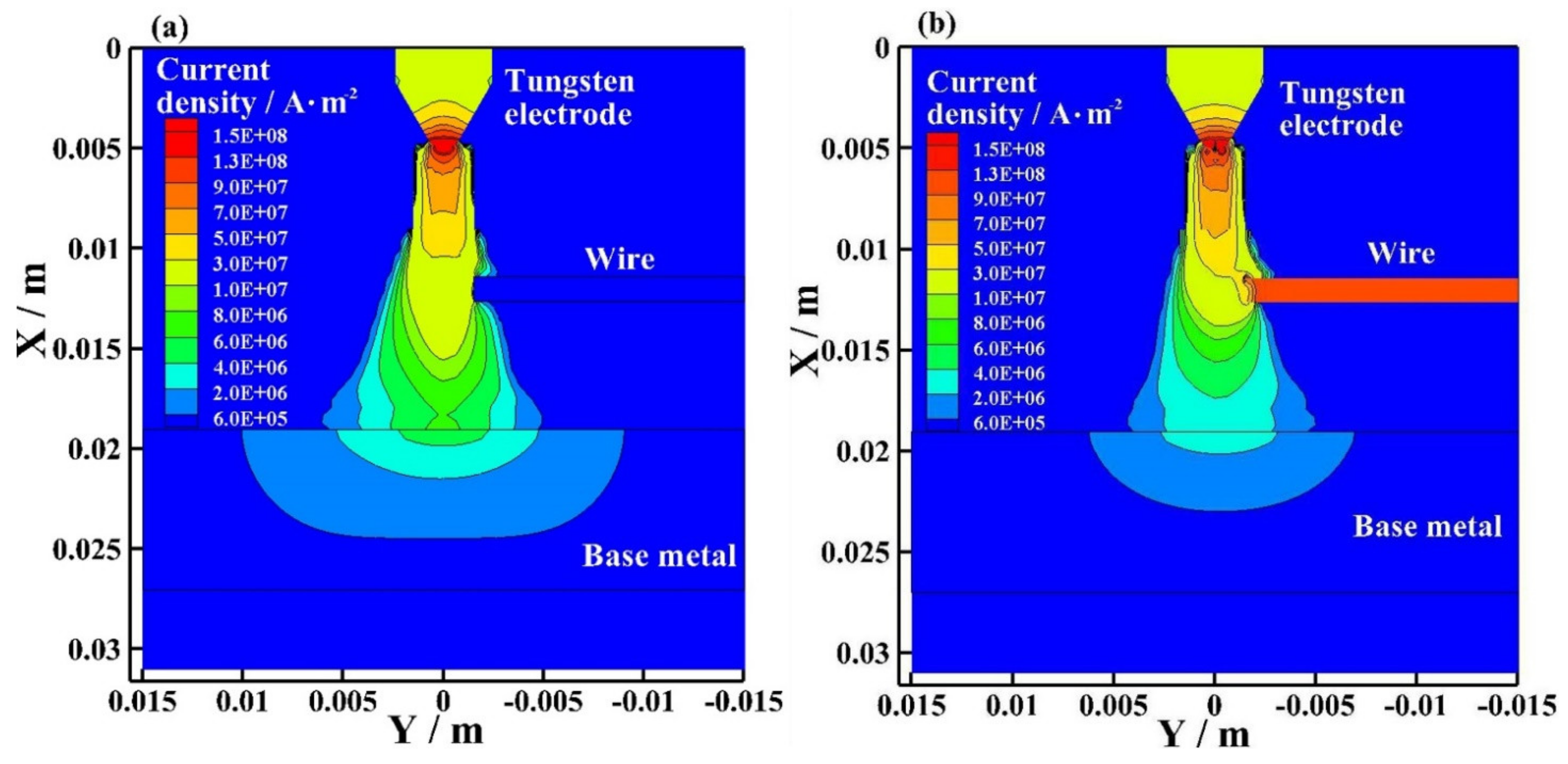
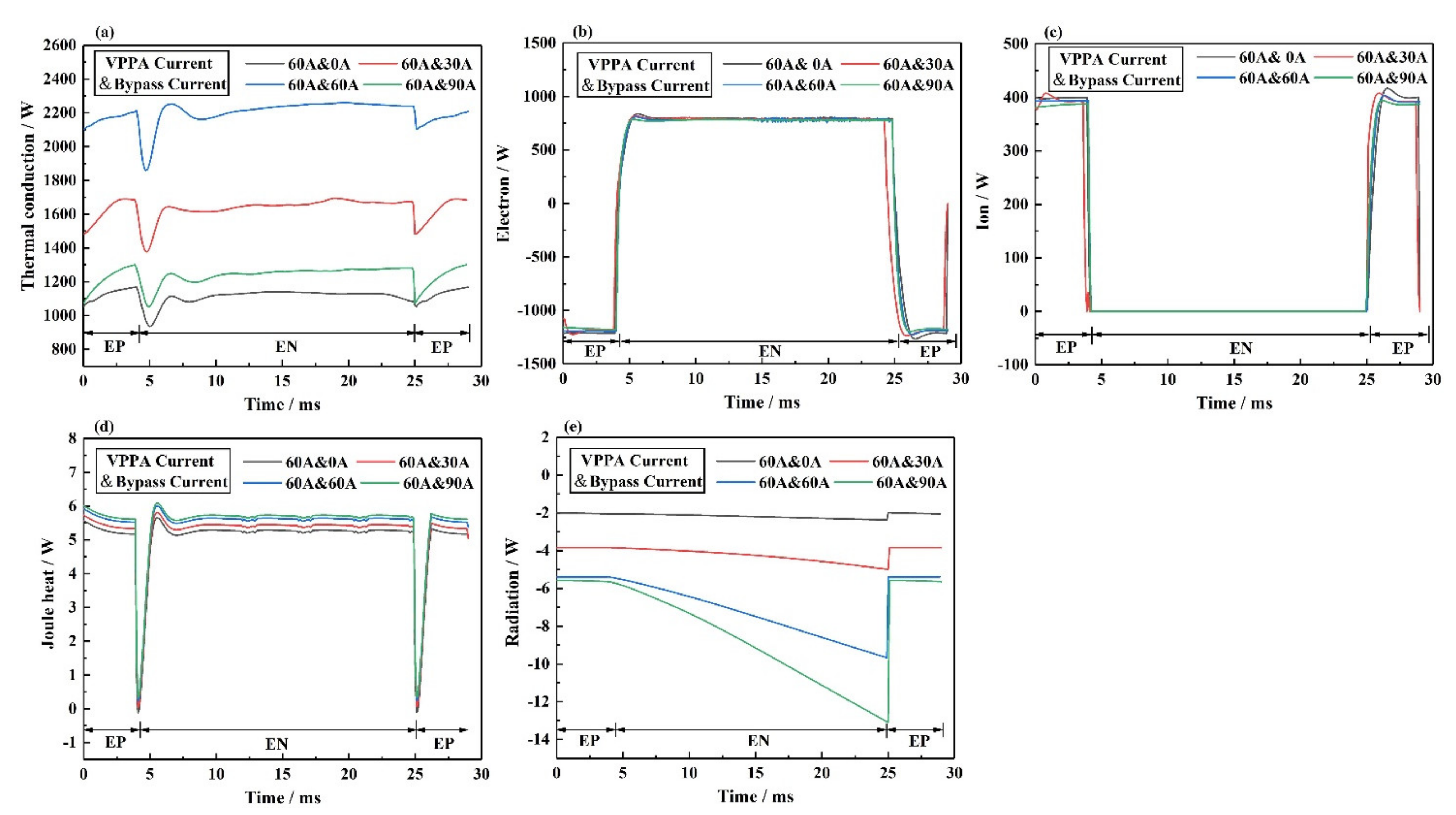
- By comparing the heat transfer on the electrodes’ boundary, it is found that this new coupling arc can control the decoupling of heat transfer between the arc and electrodes. However, the degree of heat transfer decoupling in the process is not 100%;
- (3)
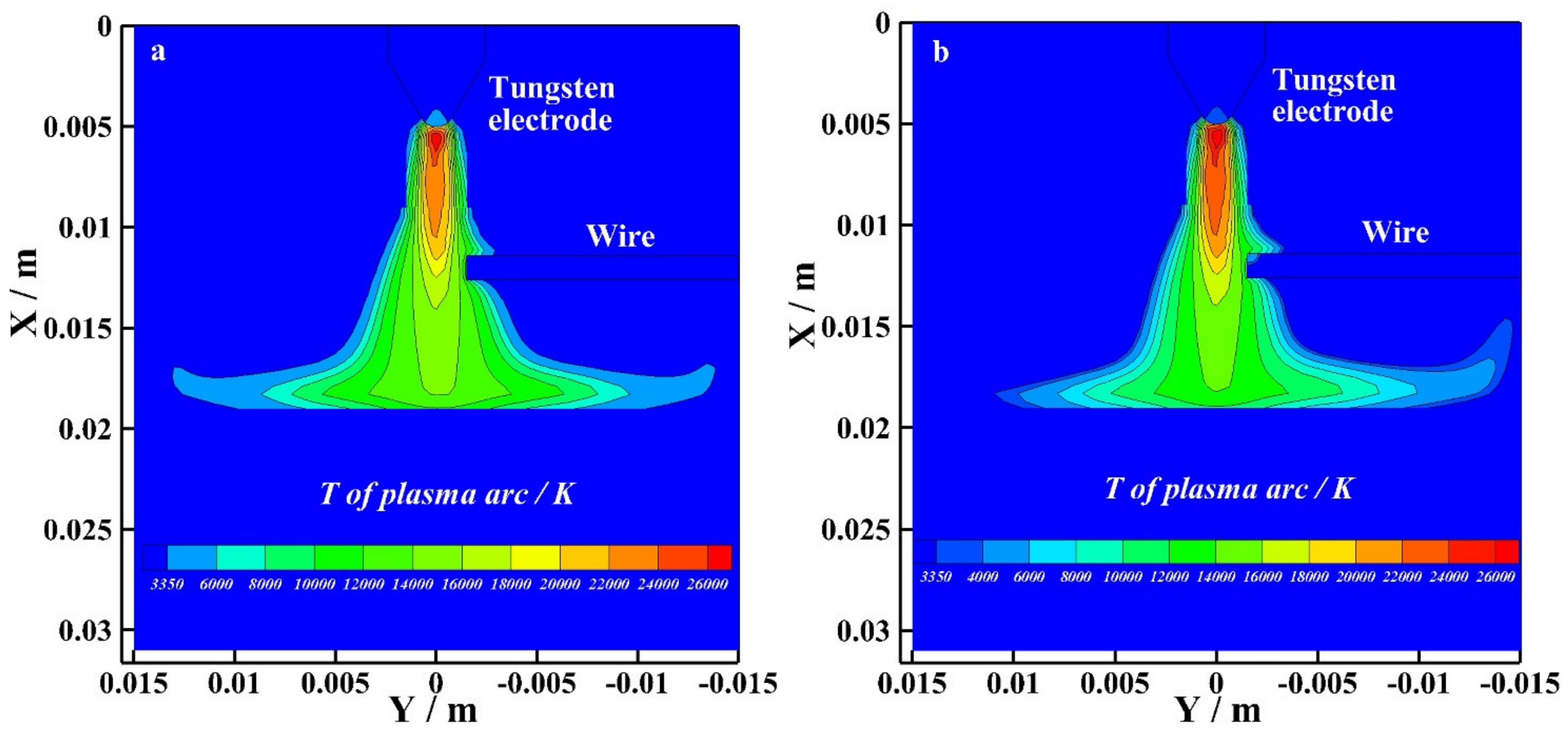
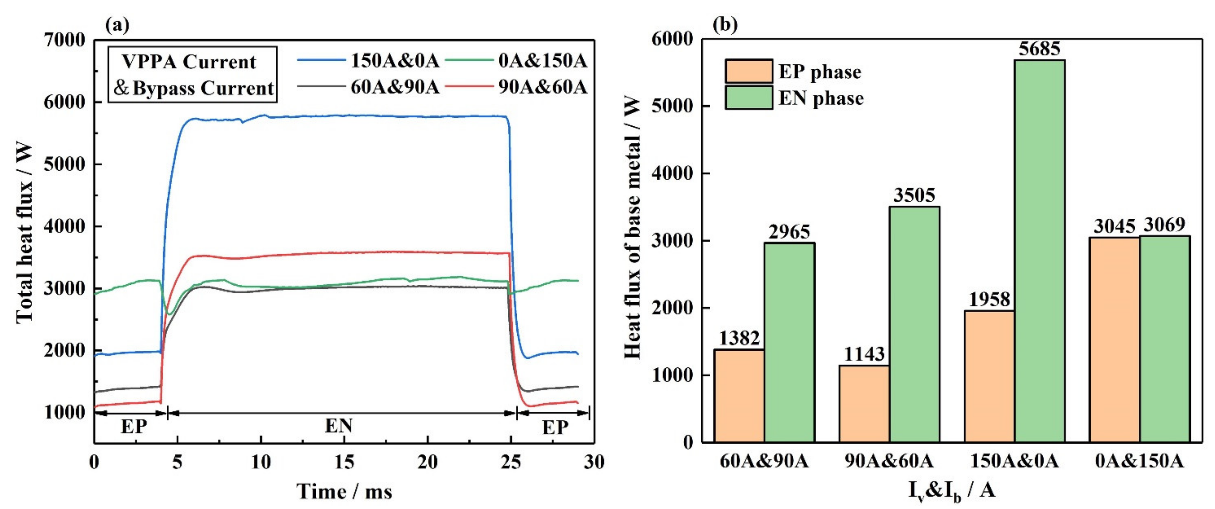
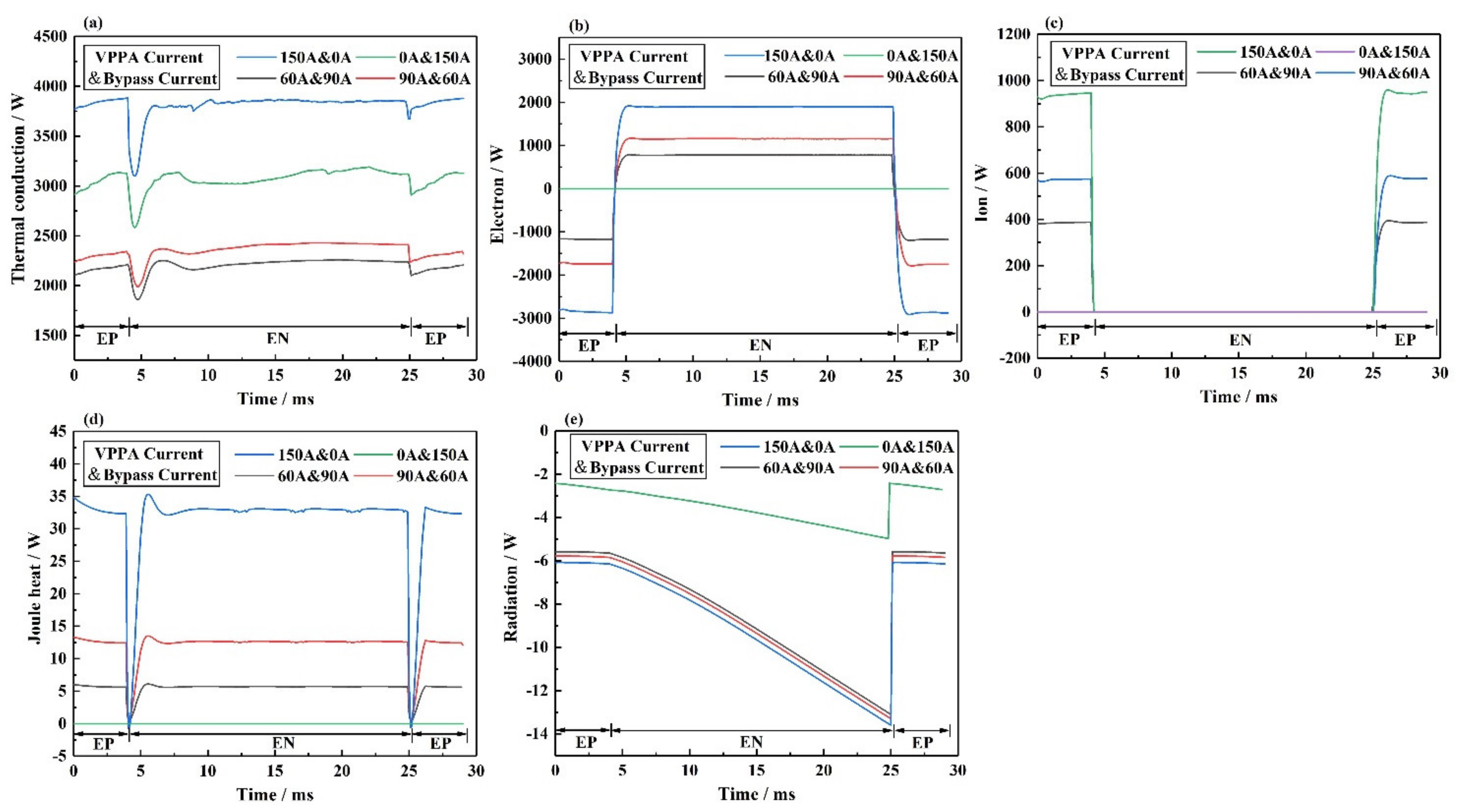
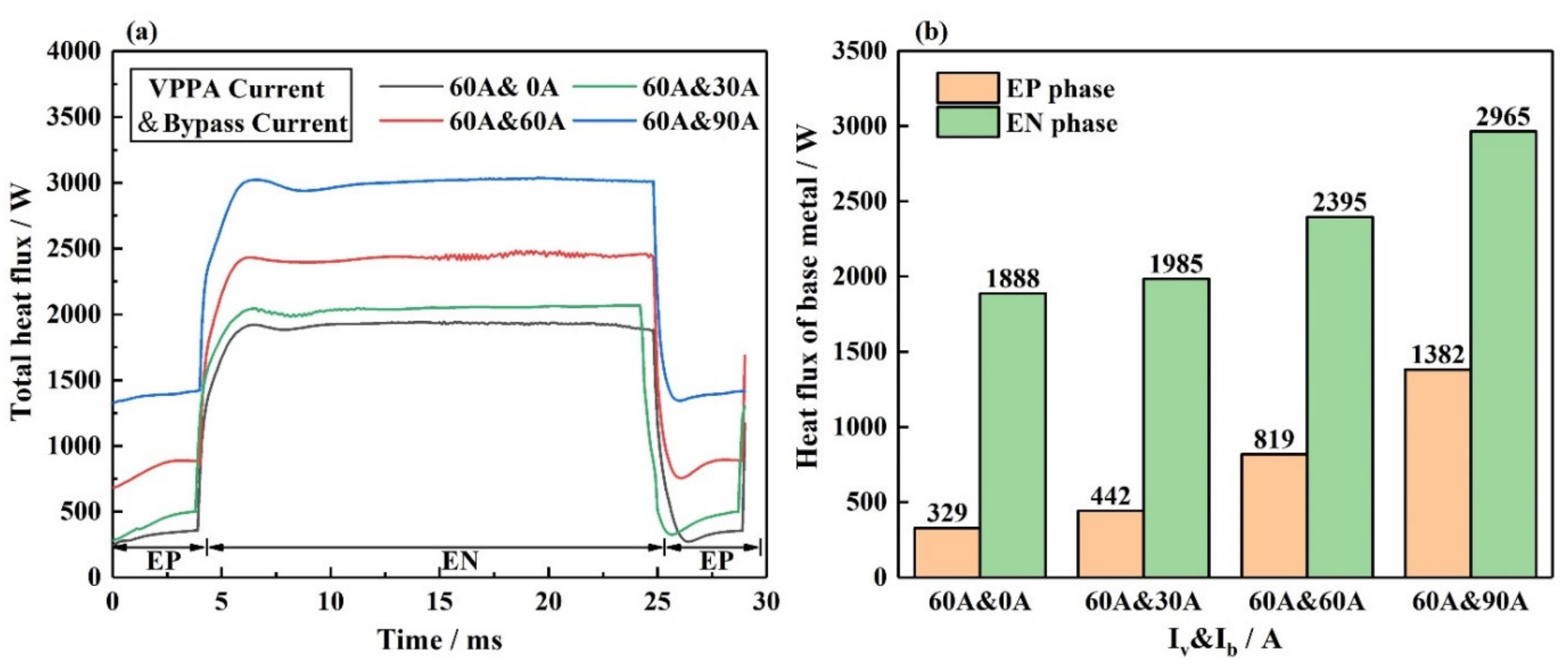
- In this process, the bypass arc affects the heat input of the base metal mainly by increasing thermal conduction to the base metal. The thermal conduction between the arc and base metal is mainly determined by the arc temperature. With the increase in the bypass current, the influence of the bypass arc on the base metal thermal conduction also increases.
Author Contributions
Funding
Conflicts of Interest
References
- Balaguru, S.; Gupta, M. Hardfacing studies of Ni alloys: A critical review. J. Mater. Res. Technol. 2021, 10, 1210–1242. [Google Scholar] [CrossRef]
- Zhao, H.H.; Zhang, G.J.; Yin, Z.Q.; Wu, L. Finite element analysis of temperature field during multi-layer multi-pass weld-based rapid prototyping. China Weld. 2011, 20, 1–5. [Google Scholar]
- Dutra, J.C.; Cirino, L.M.; Gonçalves, R.H. AC-GTAW of aluminium—New perspective for evaluation of role of positive polarity time. Sci. Technol. Weld. Join. 2013, 15, 632–637. [Google Scholar] [CrossRef]
- Thivillon, L.; Bertrand, P.; Laget, B.; Smurov, I. Potential of direct metal deposition technology for manufacturing thick functionally graded coatings and parts for reactors components. J. Nucl. Mater. 2009, 385, 236–241. [Google Scholar] [CrossRef]
- Theriault, A.; Xue, L.; Dryden, J. Fatigue behavior of laser consolidated IN-625 at room and elevated temperatures. Mater. Sci. Eng. A 2009, 516, 217–225. [Google Scholar] [CrossRef] [Green Version]
- Xiong, J.T.; Geng, H.B.; Lin, X. Research status of wire and arc addictive manufacture and its application in aeronautical manufacturing. Aeronaut. Manuf. Technol. 2015, 58, 80–85. [Google Scholar]
- Xu, B.; Tashiro, S.; Jiang, F.; Chen, S.; Tanaka, M. Effect of Arc Pressure on the Digging Process in Variable Polarity Plasma Arc Welding of A5052P Aluminum Alloy. Materials 2019, 12, 1071. [Google Scholar] [CrossRef] [Green Version]
- Dong, S.; Jiang, F.; Xu, B.; Chen, S. Influence of polarity arrangement of inter-wire arc on droplet transfer in cross-coupling arc welding. Materials 2019, 12, 3985. [Google Scholar] [CrossRef] [Green Version]
- Katou, M.; Oh, J.; Miyamoto, Y.; Matsuura, K.; Kudoh, M. Freeform fabrication of titanium metal and intermetallic alloys by three-dimensional micro welding. Mater. Des. 2007, 28, 2093–2098. [Google Scholar] [CrossRef]
- Ueyama, T.; Era, T.; Uezono, T.; Tong, H. Application of digital inverter-controlled AC pulsed MIG welding system to light metal joining. Weld. Int. 2011, 25, 676–682. [Google Scholar] [CrossRef]
- Bender, E.M.; Drellishak, S.; Fokkens, A.; Goodman, M.W.; Mills, D.P.; Poulson, L.; Saleem, S. Grammar prototyping and testing with the LinGO grammar matrix customization system. In Proceedings of the ACL 2010 System Demonstrations, Uppsala, Sweden, 13 July 2010; pp. 1–6. [Google Scholar]
- Ebrahimnia, M.; Goodarzi, M.; Nouri, M.; Sheikhi, M. Study of the effect of shielding gas composition on the mechanical weld properties of steel ST 37-2 in gas metal arc welding. Mater. Des. 2009, 30, 3891–3895. [Google Scholar] [CrossRef]
- Zhang, Y.M.; Jiang, M.; Lu, W. Double Electrodes Improve GMAW Heat Input Control. Weld. J. 2004, 83, 39–41. [Google Scholar]
- Li, K.H.; Chen, J.S.; Zhang, Y.M. Double-electrode GMAW Process and Control. Weld. J. 2007, 86, 231s–237s. [Google Scholar]
- Li, K.H.; Zhang, Y.M. Consumable Double-electrode GMAW Part I: The Process. Weld. J. 2008, 87, 11s–17s. [Google Scholar]
- Li, K.H.; Zhang, Y.M. Consumable Double-electrode GMAW Part II: Monitoring, Modeling, and Control. Weld. J. 2008, 87, 44s–50s. [Google Scholar]
- Huang, J.K.; Yang, M.H.; Yu, S.R.; Shi, Y.; Fan, D. Study on the Dynamic Behavior of Molten Pool during the Stationary Pileup of the Double-electrode Micro Plasma Arc Welding. Chin. J. Mech. Eng. 2017, 54, 42–47. [Google Scholar] [CrossRef] [Green Version]
- Yu, S.R.; Cheng, N.D.; Huang, J.K.; Yu, X.Q.; Fan, D. Relationship between thermal process and microstructure during additive manufacturing of double-electrode gas metal arc welding. Trans. China Weld. Inst. 2019, 40, 25–29. [Google Scholar]
- Fan, D.; Zhu, M.; Shi, Y.; Huang, J.K. Digitalization and intellectualization for Double-Electrode Gas Metal Arc Welding Process In International Welding Special Report BBS; Chinese Institute of Industrial Engineering: Shanghai, China, 2013; pp. 42–47. [Google Scholar]
- Zhu, M.; Shi, Y.; Huang, J.K. Simulation and control of consumable DE-GMAW process. Chin. J. Mech. Eng. 2012, 48, 45–49. [Google Scholar] [CrossRef]
- Zhu, M.; Shi, Y.; Wang, G.L. Simulation and experiment of decoupling control for consumable DE-GMAW. Chin. J. Mech. Eng. 2012, 48, 46–51. [Google Scholar] [CrossRef]
- Yang, D.Q.; He, C.J.; Zhang, G.J. Forming characteristics of thin-wall steel parts by double electrode GMAW based additive manufacturing. J. Mater. Processing Technol. 2016, 227, 153–160. [Google Scholar] [CrossRef]
- Yang, D.Q.; Wang, G.; Zhang, G.J. Thermal analysis for single-pass multi-layer GMAW based additive manufacturing using infrared thermography. J. Mater. Processing Technol. 2017, 244, 215–224. [Google Scholar] [CrossRef]
- Joseph, A.; Farson, D.; Harwig, D.; Richardson, R. Influence of GMAW-P current waveforms on heat input and weld head spape. Sci. Technol. Weld. Join. 2005, 10, 311–318. [Google Scholar] [CrossRef]
- Ueyama, T.; Tong, H.; Yazawa, I.; Hirami, M.; Kihara, T.; Nakata, K.; Ushio, M. Aluminum alloy sheet welding by the laser AC pulsed MIG hybrid process. Weld. Int. 2004, 18, 345–350. [Google Scholar] [CrossRef]
- Tong, H.; Ueyama, T. Improvement of aluminum alloy sheet metal welding quality and productivity with AC pulsed MIG welding system. Weld. Int. 2009, 15, 851–856. [Google Scholar] [CrossRef]
- Tanaka, M.; Tashiro, S.; Lowke, J.J. Predictions of Current Attachment at Thermionic Cathode for Gas Tungsten Arc at Atmospheric Pressure; IIW: Quebec, QC, Canada, 2006. [Google Scholar]
- Morrow, R.; Lowke, J.J. A one-dimensional theory for the electrode sheaths of electric arcs. J. Phys. D Appl. Phys. 1993, 26, 634–642. [Google Scholar] [CrossRef]
- Ushio, M.; Fan, D.; Tanaka, M. A method of estimating the space-charge voltage drop for thermionic arc cathodes. J. Phys. D Appl. Phys. 1994, 27, 561–566. [Google Scholar] [CrossRef]
- Xu, B.; Tashiro, S.; Jiang, F.; Tanaka, M.; Chen, S. The effect of electrode energy balance on variable polarity plasma arc pressure. Int. J. Heat Mass Transf. 2019, 145, 118715. [Google Scholar] [CrossRef]


| 5A06 Aluminum | ||
|---|---|---|
| Thermal conductivity | k (w·m−1·k−1) | 117 |
| Specific heat | cp (J·kg−1·k−1) | 921 |
| Density | ρ (kg·m−3) | 2.8 |
| Electrical conductivity | σe (S·m−1) | 30 |
| Liquidus temperature | Ti (k) | 913 |
| Solidus temperature | Ts (k) | 873 |
| Melting temperature | T (k) | 1941 |
| Boundary | ν/(m·s−1) | T/K | φ/V | A/(Wb·m−1) |
|---|---|---|---|---|
| NM, LK | 300 | |||
| PNO | ― | 300 | ||
| FTSRQOMVUED | 300 | |||
| ML, KY | ― | 300 | ||
| ABC | 300 | |||
| BE | 300 | A = 0 |
| Case Iv | Ib | Plasma Gas Flow Rate | Shielding Gas Flow Rate | Standoff |
|---|---|---|---|---|
| 1. 60 A | 0 A | Ar: 2.0 L/min | Ar: 15 L/min | 10 mm |
| 2. 60 A | 30 A | Ar: 2.0 L/min | Ar: 15 L/min | 10 mm |
| 3. 60 A | 60 A | Ar: 2.0 L/min | Ar: 15 L/min | 10 mm |
| 4. 60 A | 90 A | Ar: 2.0 L/min | Ar: 15 L/min | 10 mm |
| 5. 120 A | 0 A | Ar: 2.0 L/min | Ar: 15 L/min | 10 mm |
| 6. 150 A | 0 A | Ar: 2.0 L/min | Ar: 15 L/min | 10 mm |
| 7. 0 A | 150 A | Ar: 2.0 L/min | Ar: 15 L/min | 10 mm |
Publisher’s Note: MDPI stays neutral with regard to jurisdictional claims in published maps and institutional affiliations. |
© 2022 by the authors. Licensee MDPI, Basel, Switzerland. This article is an open access article distributed under the terms and conditions of the Creative Commons Attribution (CC BY) license (https://creativecommons.org/licenses/by/4.0/).
Share and Cite
Jiang, F.; Miao, Q.; Xu, B.; Tashiro, S.; Tanaka, M.; Lin, S.; Fan, C.; Chen, S. Numerical Analysis of Physical Characteristics and Heat Transfer Decoupling Behavior in Bypass Coupling Variable Polarity Plasma Arc. Materials 2022, 15, 3174. https://doi.org/10.3390/ma15093174
Jiang F, Miao Q, Xu B, Tashiro S, Tanaka M, Lin S, Fan C, Chen S. Numerical Analysis of Physical Characteristics and Heat Transfer Decoupling Behavior in Bypass Coupling Variable Polarity Plasma Arc. Materials. 2022; 15(9):3174. https://doi.org/10.3390/ma15093174
Chicago/Turabian StyleJiang, Fan, Qi Miao, Bin Xu, Shinichi Tashiro, Manabu Tanaka, Sanbao Lin, Chenglei Fan, and Shujun Chen. 2022. "Numerical Analysis of Physical Characteristics and Heat Transfer Decoupling Behavior in Bypass Coupling Variable Polarity Plasma Arc" Materials 15, no. 9: 3174. https://doi.org/10.3390/ma15093174