There is still a lot of production activity in the field of machining, and so there is a need for continuous improvement in this area. Rotary tool machining is considered one of the usable methods for future machining. It can be applied in the process of milling, planing and turning of materials with enhanced mechanical properties [
1,
2]. Based on the mode of rotation occurrence in a rotary tool in the machining process, we know two basic modes of rotation, namely, a tool with constrained rotation (SPRT) and a tool with forced rotation (ADRT) [
1,
3,
4]. Tools with constrained rotation have a rotational motion derived from the friction forces generated between the workpiece and the tool contact surfaces [
5]. This type of tool does not require a separate drive for its rotation [
6]. On the other hand, tools with forced rotation have rotary motion provided from an external drive. The latter does not have to be part of the machine tool, especially in the case of conventional machine tools [
7]. If the technology is used for CNC (Computer Numeric Control) machines, the CNC machine can provide the tool drive. However, the machine in question must have the possibility to machine-driven tools, for example, directly or with the help of a driven tool holder. The machining productivity highly depends on the tooling material used and its cutting and working properties, especially when machining materials with increased mechanical properties [
8]. Machining of refractory steels and alloys is associated with high cutting forces and considerable thermal loading of the cutting edge of the tool. In order to ensure machining efficiency, tools must meet high cutting wedge strength and resistance to thermal stresses. It should be noted that turning tools made from high-speed steel and sintered carbides may not always meet the above two requirements. An option is applying ceramic cutting inserts, which have a good service life but a high price [
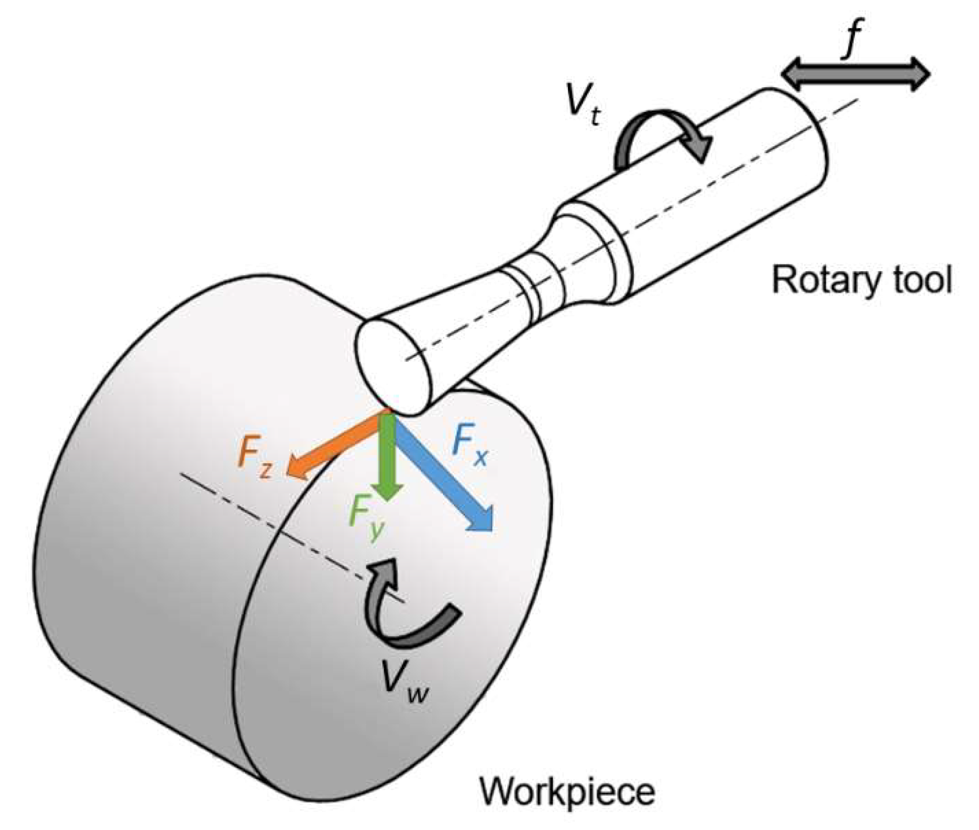
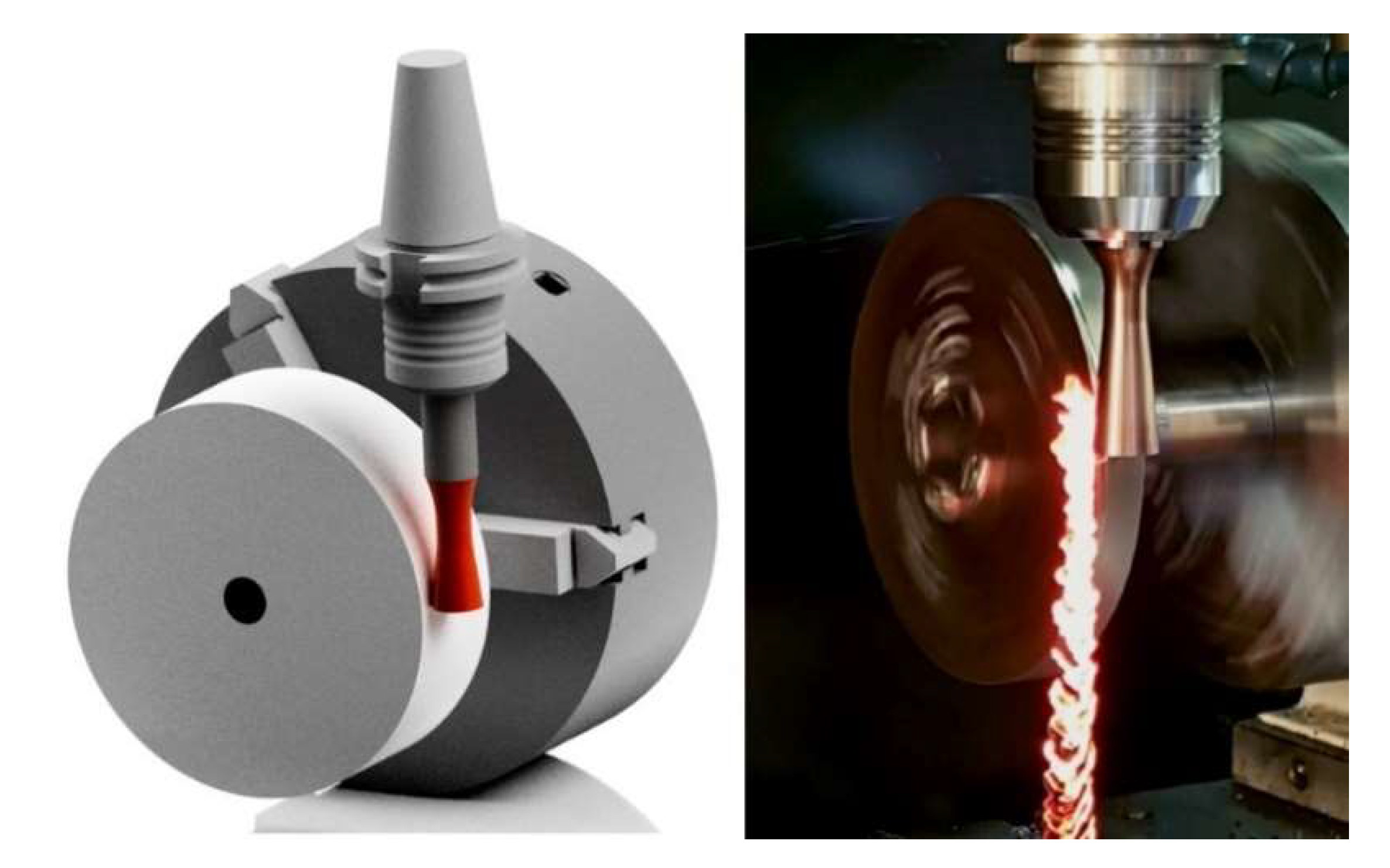
9]. Different designs of rotary circular tools can be a solution to these requirements due to the use of different kinematic cutting schemes (
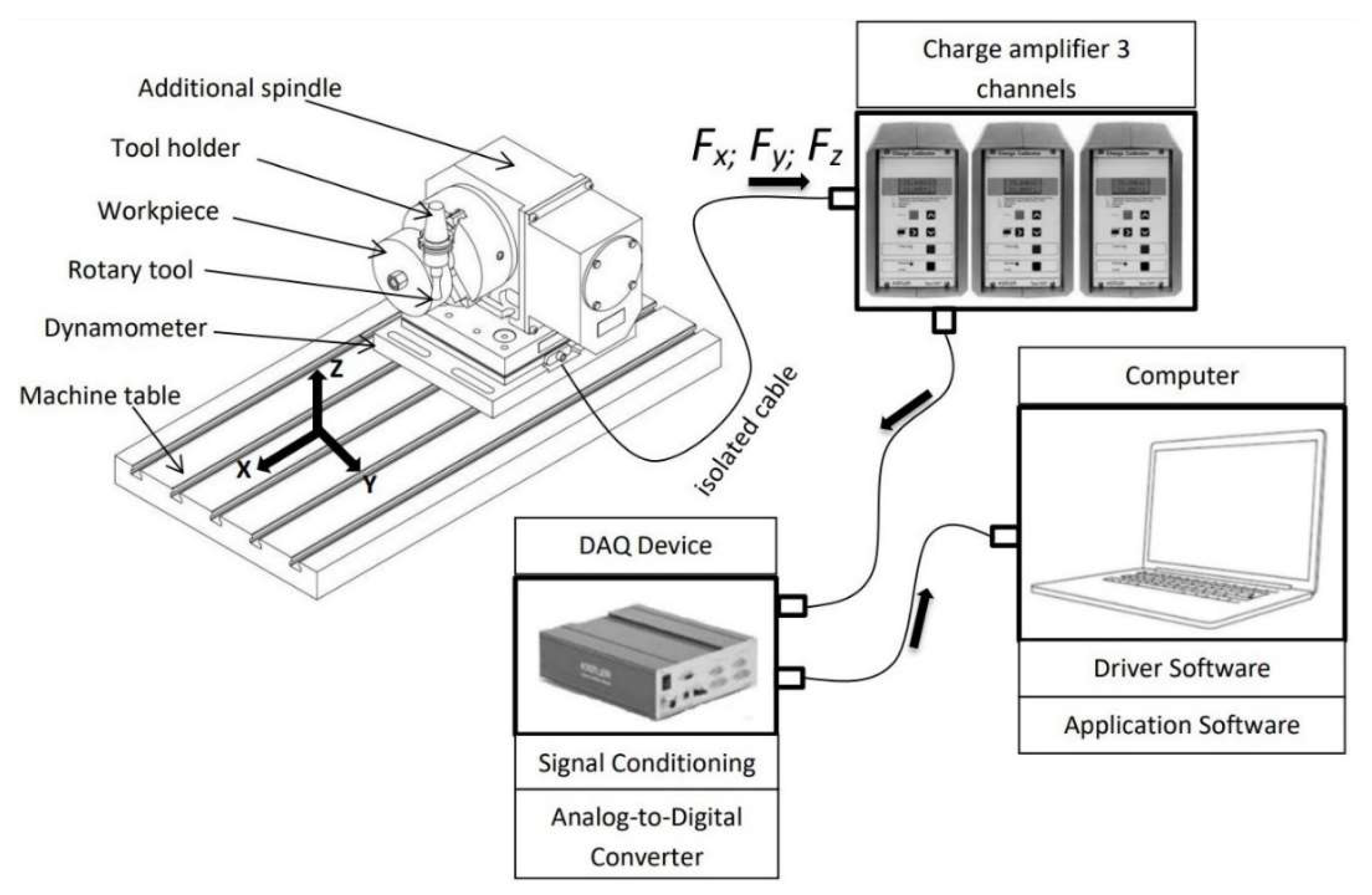
Figure 1). The setting of parameters such as workpiece rotation speed (
vw), tool rotation speed (
vt), feed rate (
f) or the direction of cutting force components (
Fx,
Fy,
Fz) is different in such kinematic schemes compared to standard turning. The tool is cooled to a greater extent compared to conventional methods due to the effect of its rotation [
10]. The rotation of the cutting part of the tool arranges a better heat dissipation around its circumference due to the contact of only one point of the cutting edge at each time [
11]. Nguyen et al. analysed the machining process with rotary tools and machined quality of the rotary turning of the hardened steel materials under a variety of machining parameters. The highest values of depth of cut (0.6 mm), cutting speed (200 m·min
−1) and feed rate (0.6 mm) can be used to increase energy efficiency. The lowest values for depth of cut (0.2 mm) and feed rate (0.2 mm) are recommended to reduce roughness. The highest level of cutting speed can be used to achieve a smoother surface [
12]. The main difference from auto-rotating tools, whose rotational motion is dependent on the machining parameters, is that in tools with forced rotation, the frequency of rotation can be controlled, and its character can be changed with the help of an external actuator. Thus, it is realistically possible to test several options and arrange possibly better productivity than auto-rotating tools.
Some practical tests of forced-motion tools have shown that the ability to handle mechanical and thermal loads on the tool were surprisingly effective compared to conventional machining methods. Available reported records speak of up to 400 to 500% higher productivity and up to 1500 to 2000% higher tool life. According to the available test information, it has been found that radial forces decrease with increasing tool rotational speed, while axial forces increase with increasing tool speed [
4]. When machining with a tool with forced rotation, two basic options of rotary tool motion can be used in the cutting process. The rotation can be carried out in clockwise and counterclockwise directions [
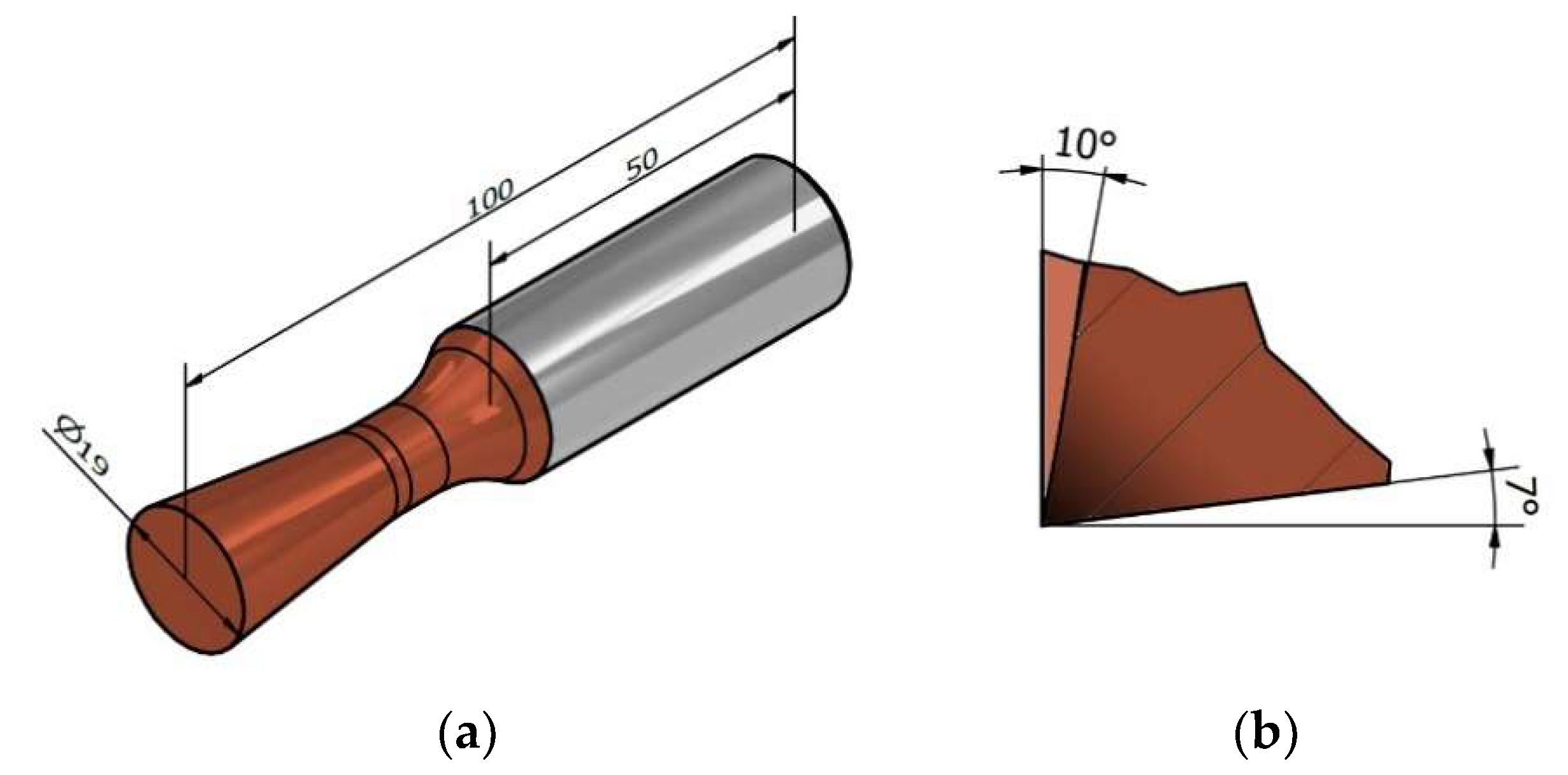
5]. In the counterclockwise orientation, observations have shown that the tool actually moves from the location where the chip is formed to a greater extent to the location with fewer chips. More surface imperfections were observed by machining in counterclockwise rotation and by increasing the rotational speed of the tool used. Another parameter that affects the machining process by forced rotation is the angle of inclination of the cutting edge to the workpiece axis (λs). In forced rotation, this angle does not fundamentally affect the rotational speed of the tool, as it is provided by an external drive unit. For a correct setting, it is necessary to investigate λs, since at certain values, there can be a critical increase in cutting force [
13,
14]. High temperatures are generated at the cutting point when machining materials and overall high cutting forces are generated [
15]. For this reason, conventional tools must be designed to have high cutting wedge strength and also cutting wedge resistance to high temperatures. However, the problem with conventional tools still remains the fact that in the machining process, the same part of the tool is always worn on the tool, which will mainly affect the machining quality and durability of the tool [
4,
10,
16]. For a better understanding of the forced rotation machining process, it is necessary to know the force loads at different rotation settings. It can be assumed that the direction of rotation alone will have different results for different machined materials. Cutting tool manufacturers have very limited options for eliminating unwanted vibrations; these include cutting tool geometry, tool body material and, where appropriate, cutting tools with integrated vibration damping mechanisms. In the presented paper, the elimination of unwanted vibrations is addressed by a non-standard cutting tool geometry.


 ,
, 


