
Increase in Stability of an X-Configured AUV through Hydrodynamic Design Iterations with the Definition of a New Stability Index to Include Effect of Gravity


Abstract
:1. Introduction
2. Stability Indices
2.1. Controls Fixed Linear Dynamic Stability Index for the Horizontal Plane
2.2. Controls Fixed Linear Dynamic Stability Index for the Vertical Plane
3. CFD Simulations
- Planar motion mechanism;
- Turn-circle maneuver.
3.1. Planar Motion Mechanism
3.2. Turning Circle Maneuver
4. Baseline Design
5. Iterative Design Process
6. Results
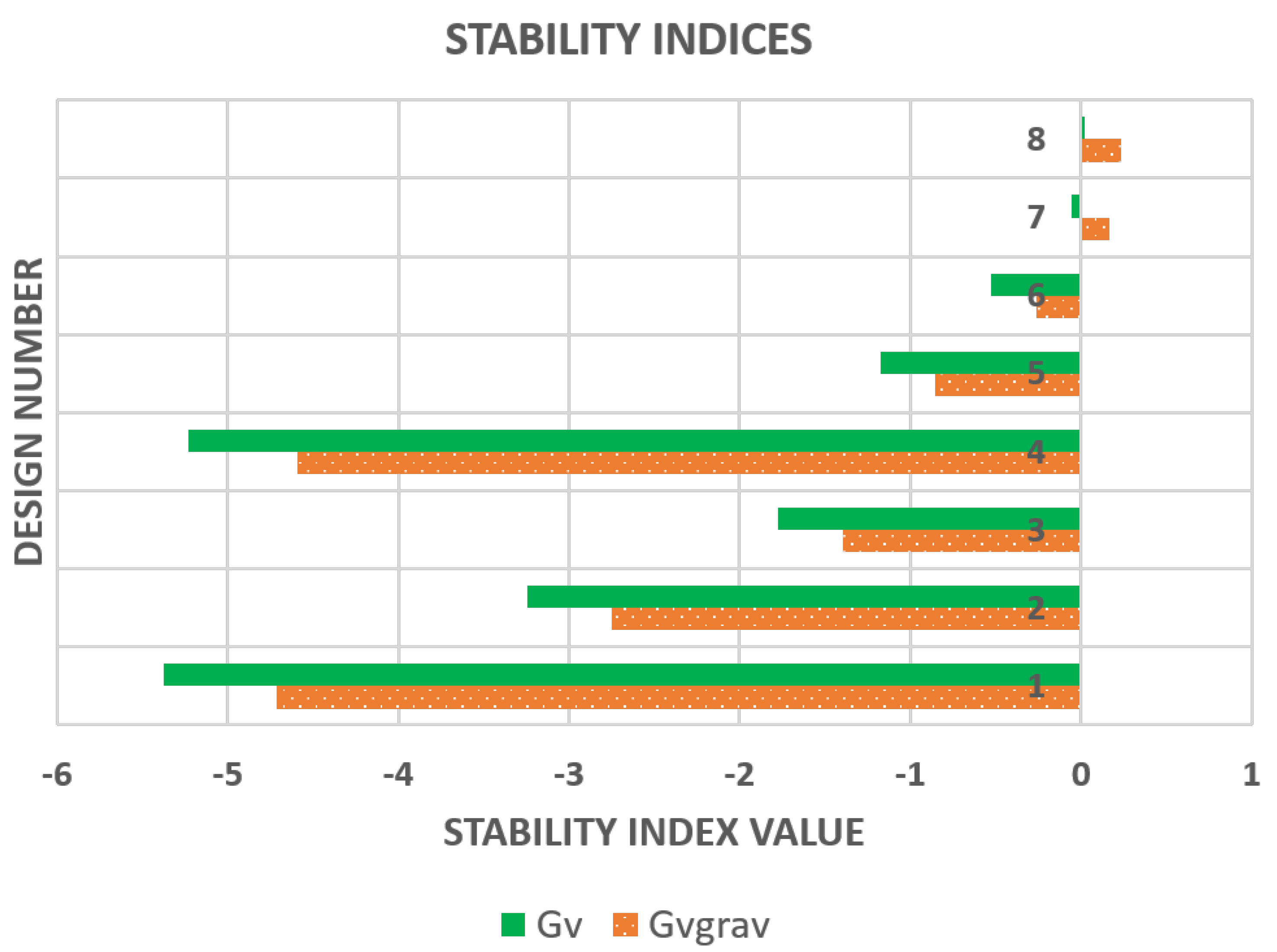
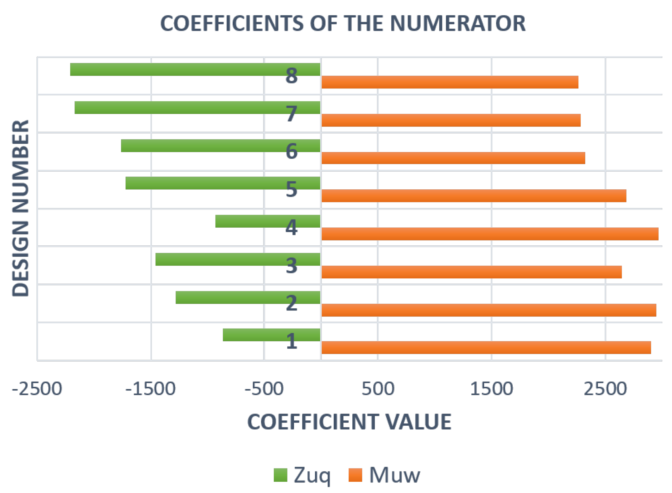
6.1. Stability Indices
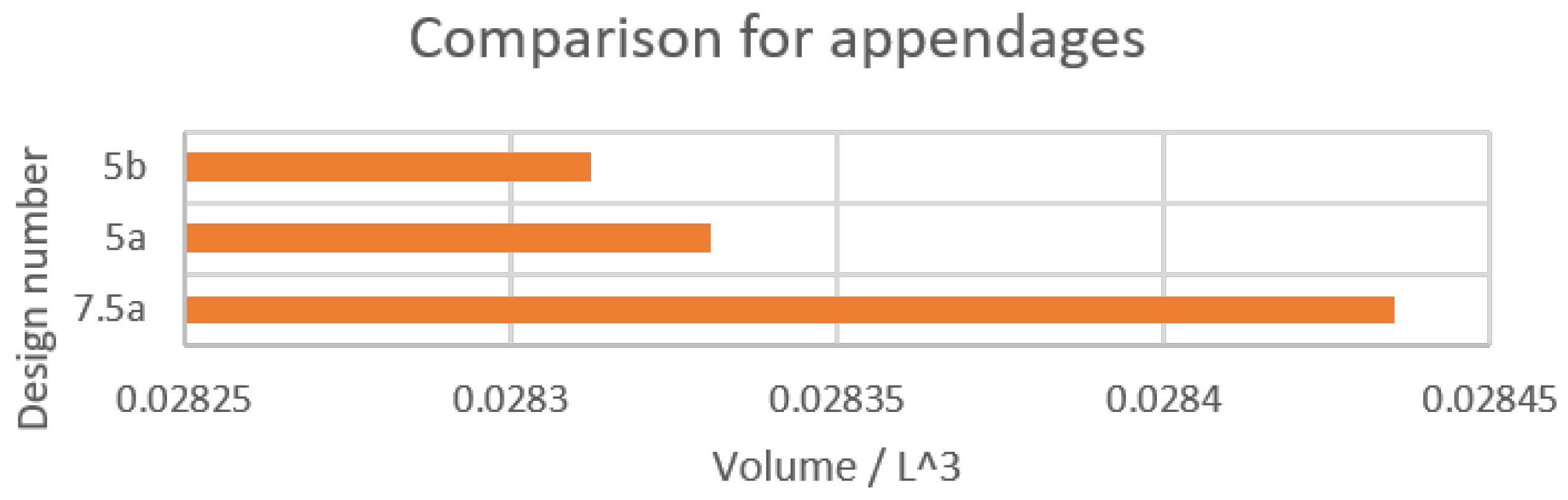
6.2. Investigation of the Sail
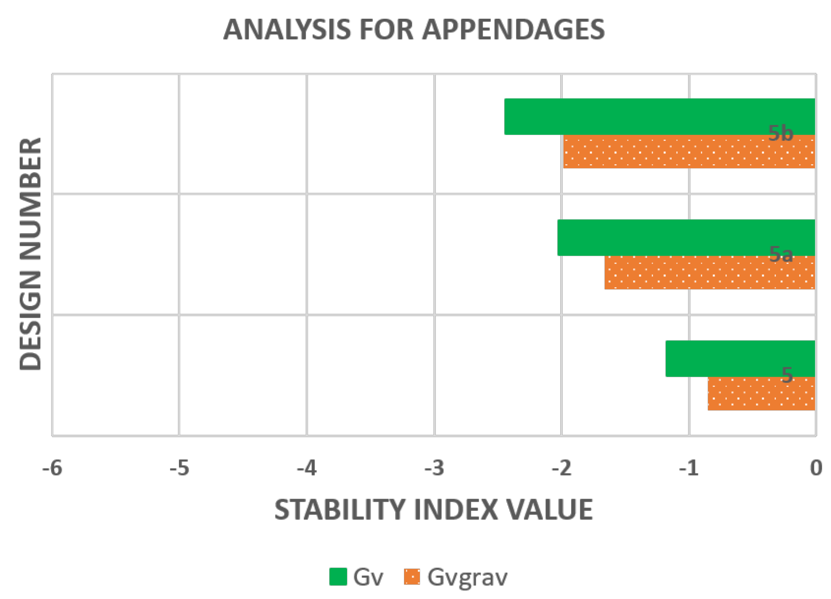
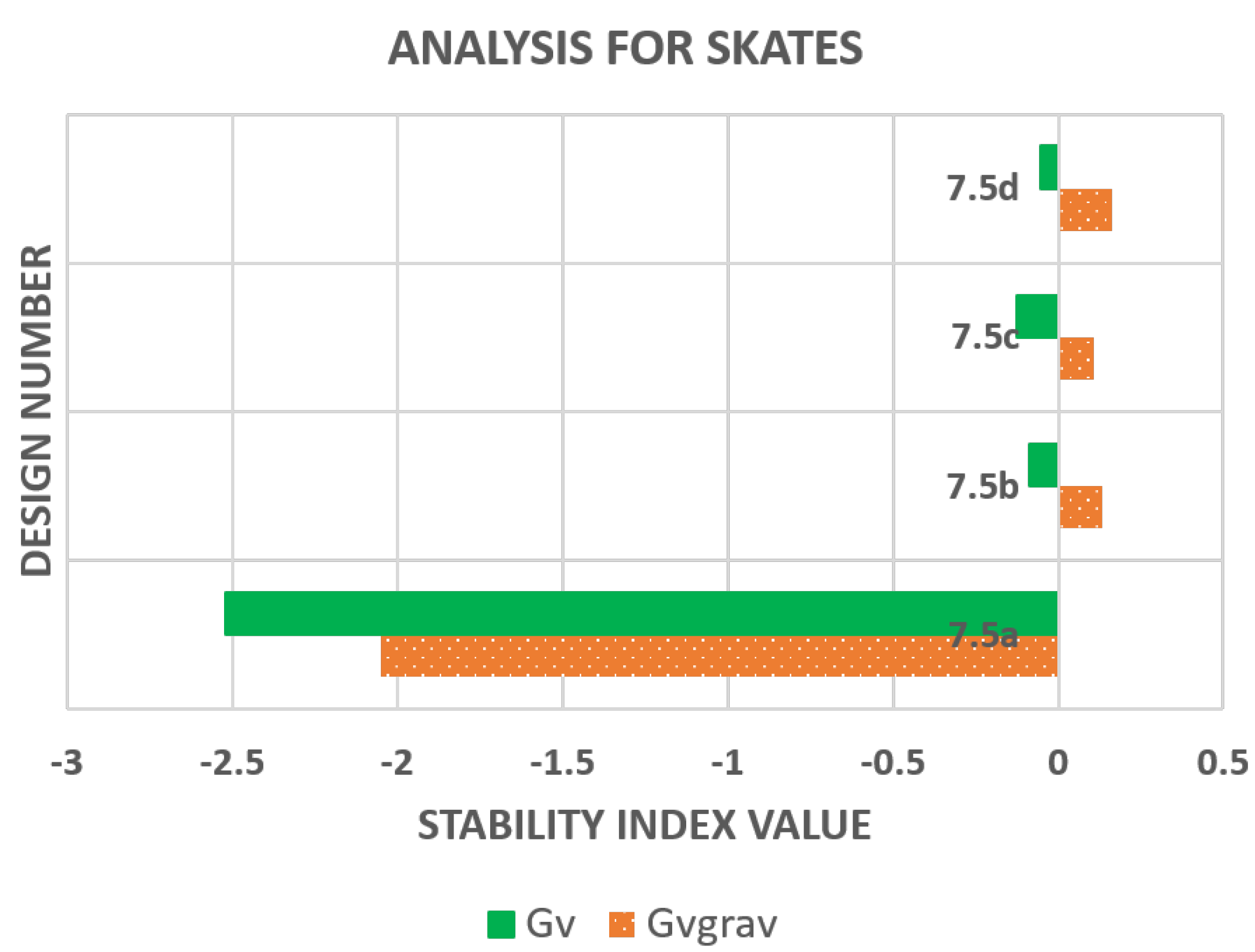
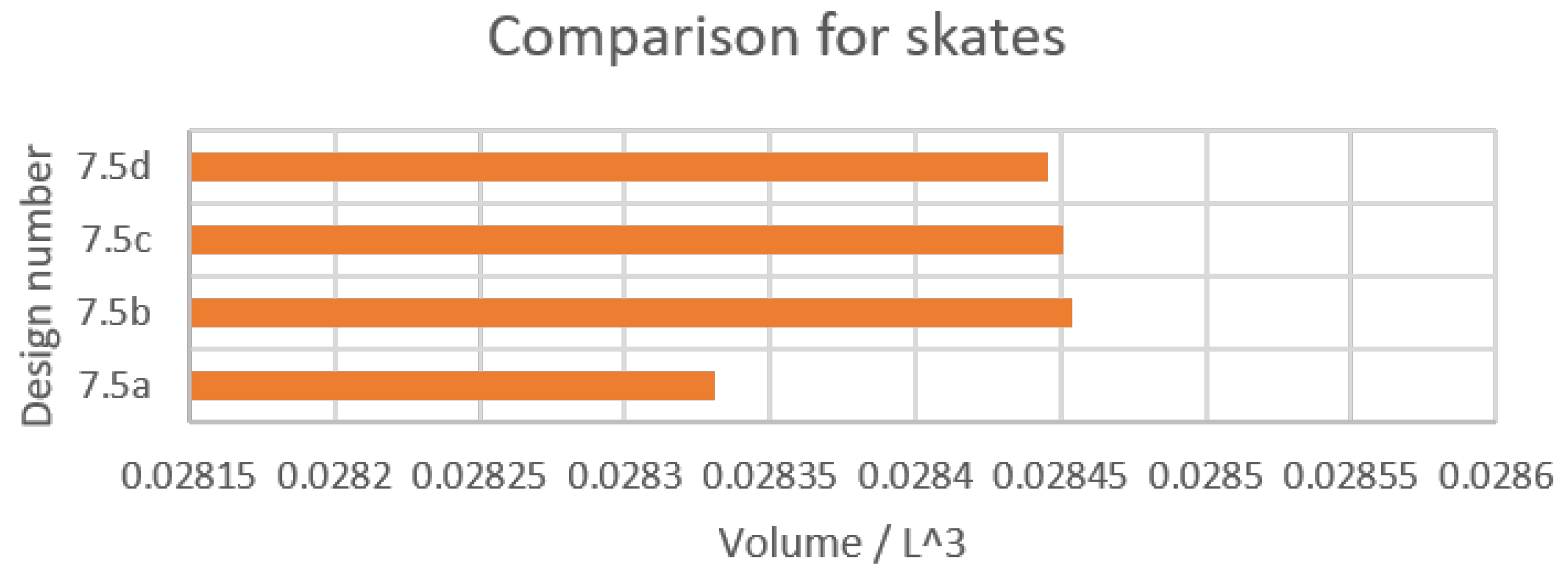
6.3. Investigation of the Skates
7. Assessment of Implications of Stability Analysis
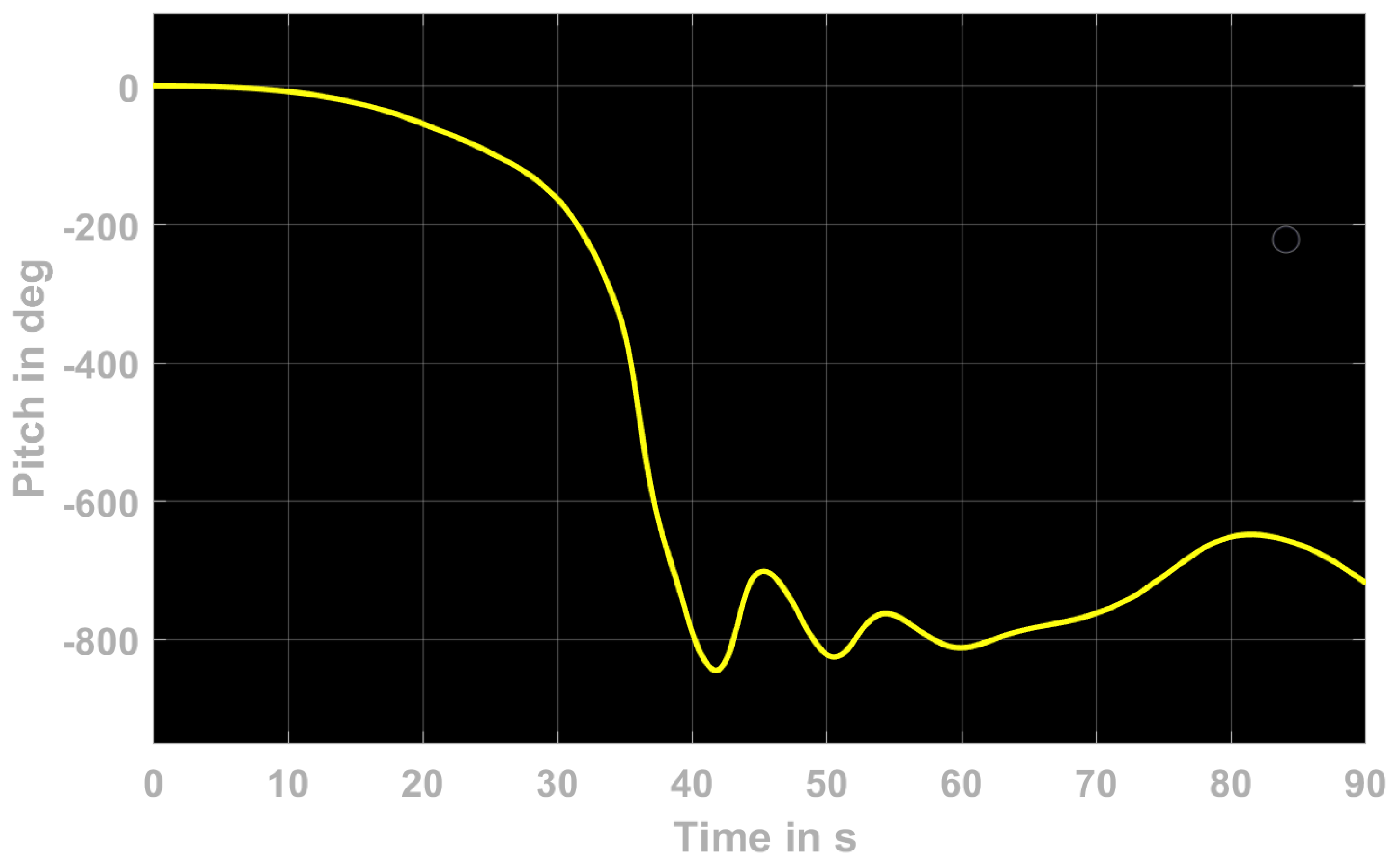
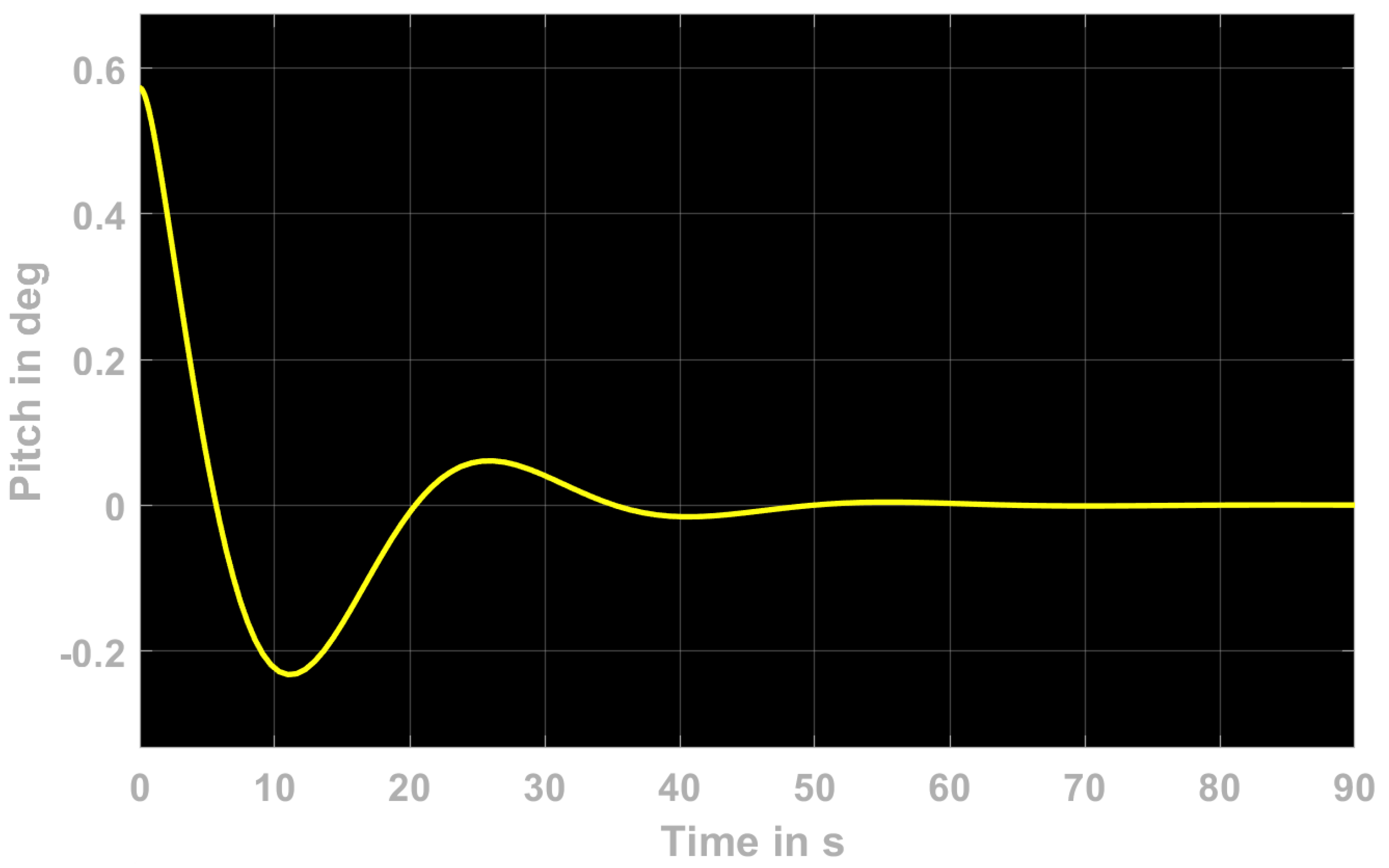
7.1. Pitching/Yawing Maneuver for the Vertical and Horizontal Planes for Verification of Stability
7.2. Circular Maneuver for CFD Validation of Stability
8. Closing Remarks and Future Work
Author Contributions
Funding
Institutional Review Board Statement
Informed Consent Statement
Conflicts of Interest
References
- Minnick, L. A Parametric Model for Predicting Submarine Dynamic Stability in Early Stage Design. Ph.D. Thesis, Virginia State and Polytechnical University, Blacksburg, VA, USA, 2006. [Google Scholar]
- Sweat, C.W. Hydrodynamic Stability Criteria for Adequate Torpedo Stability And Response; Technical Report; Department of the Navy: China Lake, CA, USA, 1958.
- Lambert, J. The Effect of Changes in the Stability Derivatives on the Dynamic Behaviour of a Torpedo; Technical Report; Admiralty Research Laboratory: London, UK, 1956. [Google Scholar]
- Lewis, E.V.; Society of Naval Architects and Marine Engineers (U.S.). Principles of Naval Architecture: Motions in Waves and Controllability; Principles of Naval Architecture, Society of Naval Architects and Marine Engineers: Jersey City, NJ, USA, 1988. [Google Scholar]
- Feldman, J. Method of Performing Captive-Model Experiments to Predict The Stability and Control Characteristics of Submarines; Technical Report June; Naval Surface Warfare Center: Bethesda, MD, USA, 1995. [Google Scholar]
- Roddy, R.F. Investigation of the Stability and Control Characteristics of Several Configurations of the DARPA SUBOFF Model from Captive-Model Experiments; Technical Report; David Taylor Research Center: Bethesda, MD, USA, 1990. [Google Scholar]
- Renilson, M. Submarine Hydrodynamics, 2nd ed.; Springer International Publishing: Berlin/Heidelberg, Germany, 2015; Volume 33, pp. 137–138. [Google Scholar] [CrossRef]
- Park, J.Y.; Kim, N.; Shin, Y.K. Experimental study on hydrodynamic coefficients for high-incidence-angle maneuver of a submarine. Int. J. Nav. Archit. Ocean Eng. 2017, 9, 100–113. [Google Scholar] [CrossRef] [Green Version]
- Feldman, J. Revised Standard Submarine Equations of Motion; Technical Report June; David W. Taylor Naval Ship Research and Development Center: Bethesda, MD, USA, 1979. [Google Scholar]
- Fossen, T.I. Hydrostatics. In Handbook of Marine Craft Hydrodynamics and Motion Control; John Wiley & Sons, Ltd.: Hoboken, NJ, USA, 2011; Chapter 4; pp. 59–80. [Google Scholar] [CrossRef]
- Coe, R.; Neu, W. Virtual Planar Motion Mechanism tests in a CFD environment. In Proceedings of the Virginia Space Grant Consortium Student Research Conference. 2012. Available online: https://vsgc.odu.edu/studentresearchconference/ (accessed on 15 January 2021).
- Cho, Y.J.; Seok, W.; Cheon, K.H.; Rhee, S.H. Maneuvering simulation of an X-plane submarine using computational fluid dynamics. Int. J. Nav. Archit. Ocean Eng. 2020, 12, 843–855. [Google Scholar] [CrossRef]
- Lewandowski, E.M. The Dynamics of Marine Craft Maneuvering and Seakeeping; World Scientific: Singapore, 2004. [Google Scholar]
- Spencer, J. Stability and Control of Submarines. J. R. Nav. Sci. Serv. 1980, 23, 187–205. [Google Scholar]
- Ogata, K. Modern Control Engineering; Prentice Hall: Upper Saddle River, NJ, USA, 2010. [Google Scholar]
- Bottacini, M. The Stability Coefficients of Standard Torpedos; Technical Report; Underwater Ordinance Department: China Lake, CA, USA, 1954. [Google Scholar]
- Njaka, T.; Miller, L.M.; Brizzolara, S.; Stilwell, D.J. Method for Improving Existing Maneuvering Models to Accomodate Large Drift Angles. In Proceedings of the Global Virtual Oceans, Biloxi, MS, USA, 5–30 October 2020. [Google Scholar]
- Dubbioso, G.; Muscari, R.; Ortolani, F.; Di Mascio, A. Analysis of propeller bearing loads by CFD. Part I: Straight ahead and steady turning maneuvers. Ocean Eng. 2017, 130, 241–259. [Google Scholar] [CrossRef]


| Index | Definition |
|---|---|
| G | stability criterion by Roddy [6] |
| stability parameter traditionally defined for the vertical plane of submarines | |
| stability parameter defined in this article accounting for hydrostatic force | |
| , | non-dimensionalized first order derivative of yaw moment with respect to sway (v) and yaw (r) rate, respectively |
| , | non-dimensionalized first order derivative of yaw moment with respect to heave (w) and pitch (q) rate, respectively |
| , | non-dimensionalized first order derivative of sway force with respect to sway (v) and yaw (r) rate, respectively |
| , | non-dimensionalized first order derivative of heave force with respect to heave (w) and pitch (q) rate, respectively |
| non-dimensionalized mass | |
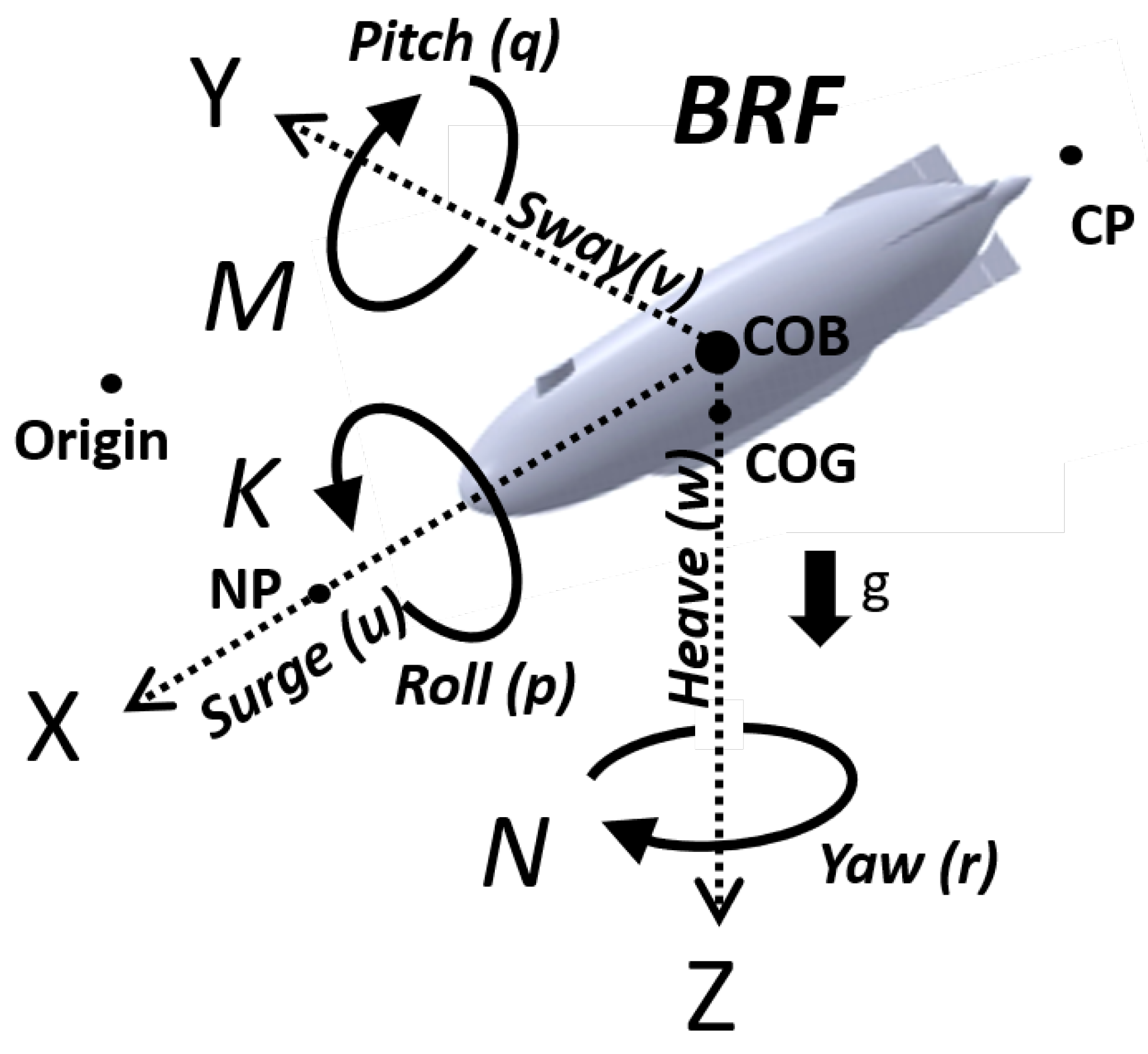
| u, v, w | velocity components along x, y and z axes in the body reference frame |
| , , | acceleration components along x, y and z axes in the body reference frame (BRF) |
| , , | coordinates of center of gravity |
| external components of force acting on the craft | |
| external moments acting on the craft about the COG | |
| rotation rate about the roll (x), pitch (y), and yaw (z) axes, respectively | |
| , , | angular acceleration about roll (x), pitch (y), and yaw (z) axes, respectively |
| vertical distance from COB to COG | |
| COG | center of gravity |
| COB | center of buoyancy |
| NP | neutral point |
| CP | critical point |
| g | acceleration due to gravity |
| coefficient of drag | |
| mass moment of inertia with respect to specified axes ‘’ and ‘’ | |
| A, B, C | coefficients of characteristic polynomial |
| variable of characteristic polynomial |
| Index | Recommended Range |
|---|---|
| 0.2 to 0.4 | |
| 0 to 0.8 |
| /D | 0.028 | 0.03 | 0.04 | 0.05 | 0.06 | 0.07 | 0.08 | |
|---|---|---|---|---|---|---|---|---|
| Fr No. | ||||||||
| 0.137 | 26 | 39 | 52 | 65 | 78 | 91 | 104 | |
| 0.27 | 7 | 10 | 13 | 16 | 20 | 23 | 26 | |
| 0.41 | 3 | 4 | 6 | 7 | 9 | 10 | 12 | |
| 0.55 | 2 | 2 | 3 | 4 | 5 | 6 | 7 | |
| 0.69 | 1 | 2 | 2 | 3 | 3 | 4 | 4 | |
| 0.82 | 1 | 1 | 1 | 2 | 2 | 3 | 3 | |
| 0.96 | 1 | 1 | 1 | 1 | 2 | 2 | 2 | |
| 1.10 | 0 | 1 | 1 | 1 | 1 | 1 | 2 | |
| 1.24 | 0 | 0 | 1 | 1 | 1 | 1 | 1 | |
| 1.37 | 0 | 0 | 1 | 1 | 1 | 1 | 1 | |
| 1.51 | 0 | 0 | 0 | 1 | 1 | 1 | 1 | |
| 1.65 | 0 | 0 | 0 | 0 | 1 | 1 | 1 | |
| 1.78 | 0 | 0 | 0 | 0 | 0 | 1 | 1 | |
| 1.92 | 0 | 0 | 0 | 0 | 0 | 0 | 1 | |
| 2.06 | 0 | 0 | 0 | 0 | 0 | 0 | 0 | |
| 2.20 | 0 | 0 | 0 | 0 | 0 | 0 | 0 | |
| 2.33 | 0 | 0 | 0 | 0 | 0 | 0 | 0 | |
| 2.47 | 0 | 0 | 0 | 0 | 0 | 0 | 0 | |
| 2.61 | 0 | 0 | 0 | 0 | 0 | 0 | 0 | |
| 2.75 | 0 | 0 | 0 | 0 | 0 | 0 | 0 | |
| Design Number | CAD Image | Description |
|---|---|---|
| Design 1 |  Baseline model | Baseline model: fully appended. The socket gap between control fins and fixed strakes is filled for CFD. |
| Design 2 |  Extended Strakes model | Extended strakes model: The control fins are extended lengthwise. |
| Design 3 |  T-Strakes model | T-strakes model: The control fins and fixed strakes are appended with a T at the edges to increase fin surface area. |
| Design 4 |  Vertical Fins model | Vertical Fins model: A vertical fin that is fixed, in addition to the four strakes, is added to the stern of the craft at the top and bottom. The added fins follow a NACA profile to minimize drag. |
| Design 5 |  Hybrid Narrow model | Hybrid narrow model: The fins are extended and have a T-shaped edge, making this model a combination of Designs 2 and 3. The T-shaped edge has a triangular leading edge to avoid stagnation. |
| Design 5a |  No-skates model | No-skates model: The skates are removed to understand the stability in the presence of the remaining appendages. |
| Design 5b |  No-appendages model | No-appendages model: The sail and skates are removed to understand the stability in the presence of the remaining appendages. |
| Design 6 |  T-Strakes Extended model | T-strakes extended model: The fins have been extended beyond those of the hybrid narrow model in the lengthwise dimension. |
| Design 7 |  Hybrid Wide model | Hybrid wide model: This model based on Design 5 and Design 6 has wider T-edges on the strakes to increase surface area and mass for the stern. |
| Design 7.5a |  No-sail model | No-sail model: No sail in the hybrid trapezoidal model. This model is a step before Design 8, the only difference being the triangular leading edge of the T strakes. |
| Design 7.5b |  Equal holes model | Equal holes model: Equally spaced holes of the same diameter placed along the skates. |
| Design 7.5c |  Unequal holes model | Unequal holes model: Holes of unequal diameter, evenly spaced, placed along the skates. |
| Design 7.5d |  Slots model | Slots model: Slot cut out in the front part of the skates, removing most material after Design 7.5a. |
| Design 8 |  Hybrid triangle model | Hybrid triangle model: The fins are extended and have T-shaped edges. The edge is shaped with a triangular leading edge and taper leading to its widest trailing edge. |
| Parameter | Value |
|---|---|
| Length | L |
| Diameter | 0.224 L |
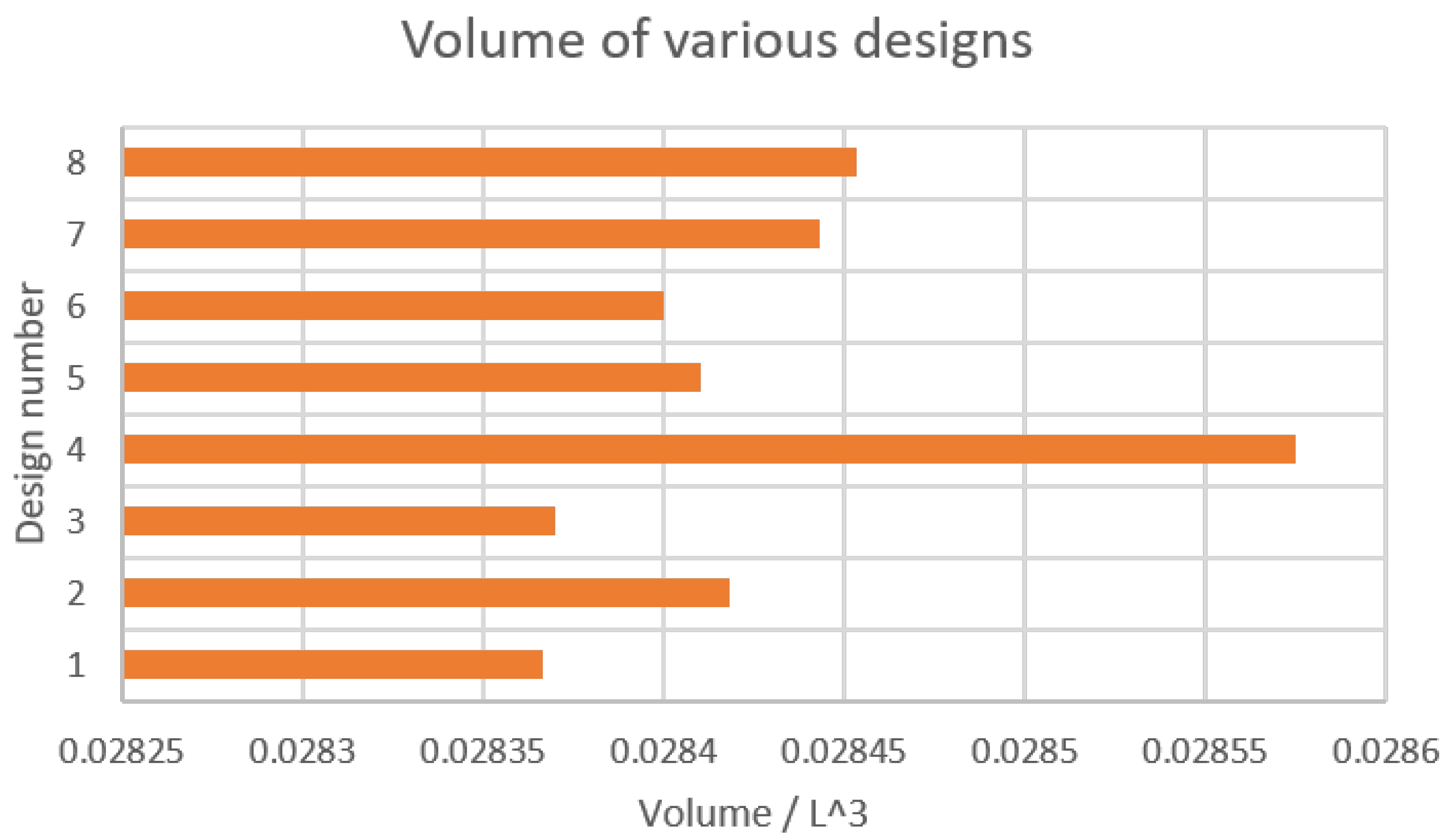
| Volume | 0.0284 L |
| Wetted Surface Area | 0.571 L |
| Cruise Speed | 4 kn |
| 0.0416 D |
| Design | |
|---|---|
| Baseline | 0.0608 |
| Hybrid wide T | 0.0879 |
| Hybrid wide triangle | 0.0878 |
| Hydrodynamic Coefficients | Design 1 | Design 2 | Design 3 | Design 4 | Design 5 | Design 6 | Design 7 | Design 8 |
|---|---|---|---|---|---|---|---|---|
| −0.0162 | 23.1 | −108 | −32.4 | −65.6 | −123 | −93.3 | −79.3 | |
| 0.0367 | 1.47 | −8.82 | 2.12 | −7.61 | −20 | −21.3 | −22 | |
| −0.000673 | 40.1 | 56.6 | −7.41 | 56.4 | 102 | 172 | 132 | |
| −0.0236 | 16.5 | −67.2 | −23.4 | −37.8 | −90.3 | −66.9 | −53.5 | |
| −0.0233 | 1.69 | 19.9 | −4.44 | 21.8 | 49.4 | 52.4 | 55.7 | |
| −0.0259 | 1.68 | 1.16 | −0.066 | 2.2 | 3.62 | 4.85 | 4.84 | |
| −0.00573 | 74.5 | −47.1 | −12.7 | −22.8 | −43.7 | −19.2 | −14.2 | |
| −0.00266 | 33.6 | 46.5 | 8.6 | 70.8 | 69.3 | 101 | 107 | |
| −0.00105 | 11 | 6.02 | 0.816 | 11.8 | 11.8 | 20.1 | 20.7 | |
| −0.014 | 72.9 | −49 | −8.53 | −25.2 | −48.4 | −25.2 | −19.4 | |
| −0.00532 | 47.4 | 68.3 | 7.76 | 98.9 | 103 | 150 | 155 | |
| −0.000218 | 109 | 110 | −1.9 | 135 | 144 | 283 | 240 |
| Hydroplanes | Design 1 | Design 2 | Design 3 | Design 4 | Design 5 | Design 6 | Design 7 | Design 8 |
|---|---|---|---|---|---|---|---|---|
| neutral point at 4 kn | −0.765 | −0.763 | −0.581 | −0.817 | −0.580 | −0.409 | −0.395 | −0.383 |
| critical point at 4 kn | 0.625 | 0.626 | 0.465 | 0.672 | 0.466 | 0.316 | 0.303 | 0.293 |
| Rudder Deflection [] | Hybrid Triangle [m] | Baseline [m] |
|---|---|---|
| 10 | 6.2 L | 3.4 L |
| 20 | 3.3 L | 2.3 L |
Publisher’s Note: MDPI stays neutral with regard to jurisdictional claims in published maps and institutional affiliations. |
© 2021 by the authors. Licensee MDPI, Basel, Switzerland. This article is an open access article distributed under the terms and conditions of the Creative Commons Attribution (CC BY) license (https://creativecommons.org/licenses/by/4.0/).
Share and Cite
Miller, L.; Brizzolara, S.; Stilwell, D.J. Increase in Stability of an X-Configured AUV through Hydrodynamic Design Iterations with the Definition of a New Stability Index to Include Effect of Gravity. J. Mar. Sci. Eng. 2021, 9, 942. https://doi.org/10.3390/jmse9090942
Miller L, Brizzolara S, Stilwell DJ. Increase in Stability of an X-Configured AUV through Hydrodynamic Design Iterations with the Definition of a New Stability Index to Include Effect of Gravity. Journal of Marine Science and Engineering. 2021; 9(9):942. https://doi.org/10.3390/jmse9090942
Chicago/Turabian StyleMiller, Lakshmi, Stefano Brizzolara, and Daniel J. Stilwell. 2021. "Increase in Stability of an X-Configured AUV through Hydrodynamic Design Iterations with the Definition of a New Stability Index to Include Effect of Gravity" Journal of Marine Science and Engineering 9, no. 9: 942. https://doi.org/10.3390/jmse9090942