1. Introduction
Ports are considered as strategic infrastructures within the international market and, in most cases, they are presented as the main economic source of the cities to which they belong, increasing the potential of being part of shipping routes [
1]. This fact highlights the importance of having a continuous service in the ports, which must always be operational. To do so, it is necessary to establish maintenance management systems appropriate to port requirements, as these facilities are exposed to numerous external agents that will hinder the correct state of conservation of the infrastructures that make up the port. Maintenance has more importance in a life cycle approach and, moreover, considering climate change [
2,
3]. Most port facilities are exposed to a very aggressive environment that makes them especially susceptible to the development of certain pathologies that will need to be repaired. A port’s facilities represent a necessary link in the chain of port operations, and any disruption can lead to poor port efficiency. In general, each year, about 11% of the operating expenses of ports are allocated to the maintenance of the facilities [
4]. Furthermore, in the cost life cycle, maintenance activities are around 25% of initial investment [
5]. In other studies, the maintenance contribution is around 60% [
6].
Materials used in the construction stage have a direct impact on the life cycle of ports in a sustainable and carbon footprint approach [
7] but also on operational activities during conservation and the durability of the infrastructure [
8,
9,
10].
In recent years, a digital transformation is being experienced in the field of civil engineering through the implementation of the building information modeling (BIM) method in construction projects, like in the case of bridges [
11,
12,
13,
14,
15,
16,
17,
18,
19,
20].
The BIM method allows for reducing costs, building in a more efficient way, and the possibility for all the agents involved in a project to carry out collaborative work. The advantages offered by this method applied to new construction projects are numerous, but not in the case of the maintenance phase. Therefore, it is necessary to implement BIM considering the entire project lifetime: design, construction, and operation.
Until now, the use of the BIM method in the management of conservation and maintenance has only been carried out in the building sector for the maintenance of facilities (e.g., [
21]). However, in the infrastructure sector, it is an issue that today is it still very undeveloped, specifically in seaports, as already noted [
22], with a critical review in relation to BIM and facility management in this kind of infrastructure. BIM and its application to port infrastructure in its life cycle (construction and maintenance) has not much literature, but there are some approaches related to BIM development for port facility operations. Some of these approaches [
23] regard the application of BIM technology in the operation of port marine structures, Refs [
24,
25] are related to the use of BIM technology for the design of the operation of ports, Ref [
26] show the application of BIM technology for the design of power pipes for liquid chemical berth, Ref [
27] relate to electrical design using BIM technology, and Ref [
28] show some software for the use of BIM in port infrastructures. All of them conclude with the lack of documentation of existing infrastructures, the great interconnections, and the continuous operation and effects on the infrastructure.
This research paper focuses on the development of a new conservation management method in which the BIM method is applied as the main tool to serve as a database for the maintenance of port infrastructures. The maintenance and operation manager systems linked with BIM is the near future for facility management in such infrastructures as ports, where the information and database are essential for the efficiency of the whole process [
29].
The main objective of this research is the creation of a new port infrastructure conservation management method that allows for combining the traditional method used so far with new technologies, specifically, the BIM method. This is very important in the current moment, when BIM is starting to be a reality, so it is essential to develop new practical methods to be able to use it based on the previous knowledge. The use of BIM for port maintenance has several advantages, one of them being the control of all the generated information in an ordered way. For most public infrastructures, the use of BIM in developed countries is compulsory, so it is a complete need.
To integrate traditional and BIM methods, the maintenance protocols based on the “Standard Practice for Underwater Investigations” have been considered [
30,
31,
32]. Following the literature related to asset management, facility management, and BIM (e.g., [
33]), the problem and main limitation in this kind of study is not the lack of information, but just the opposite (a large collection of data), so to propose processes and protocols will be necessary for achieving success in such a purpose.
Some aspects and steps to be considered to achieve the main objective are: to know how the management of the conservation of port infrastructures is currently carried out and to study possible improvements through the application of the BIM method in that process; to create a three-dimensional (3D) BIM model of a port infrastructure and expose its optimal capacity to extract information at any time during its life cycle; to give continuity to the application of the BIM Guide developed by Puertos del Estado and published in July 2019, it being the objective of the research project exposed in this paper to expand certain aspects of the maintenance and conservation management; to check the feasibility and effectiveness of the implementation of the BIM method in the management of structure maintenance, applying it to a practical case to exemplify the process; to study up to what stage of maintenance management the use of the BIM method is viable; to establish the procedures and requirements necessary for the application of the new method for the management of the maintenance of a port; to present the benefits that can be obtained from the use of BIM in maintenance management and that compensate for the great effort required to integrate the traditional method in the BIM model.
The structure of the paper is: (1) introduction of the motivation, the objectives, and the structure of the manuscript; (2) methods used in the research, including some details about the software applied and the port selected as the case study; (3) results of the definition of the proposal created in this research for the application of the BIM method to the maintenance of port infrastructures; (4) discussion of the application of the proposal exposed in the results section to the case study to validate its feasibility; (5) a conclusion, highlighting the key aspects of the research.
The significance of the paper is key in the current state of BIM development for port infrastructures. Although there are some general studies related to the use of BIM in ports, there is not a clear method for BIM use in port maintenance. This manuscript shows a new proposed method to implement BIM in the maintenance phase of ports, and its validation with a real case.
2. Research Methods
The method starts with the analysis of the existing documentation regarding how the management of the conservation of infrastructures in port environments is currently carried out, including not only the assets management method but also the main failure to be detected in main port infrastructures, like breakwaters. The aim of that analysis is achieving a technical and global vision of the fundamental aspects that will be addressed in the research. Furthermore, the state of the art of BIM technology applied to port infrastructures and even to other civil infrastructures has been reviewed. The knowledge of BIM and associated software has been essential in this study.
Based on the knowledge of how the maintenance of ports is carried out up to now, and the advantages of the BIM method for maintenance operations, a new method for assets management in ports has been created using BIM philosophy. The main steps to follow and the necessary requirements for the application of this new method have been established.
To validate the proposed method, two port infrastructure models were developed in the Revit Autodesk application, including the data referring to the maintenance and conservation of the structures, managing to create a new work method for the improvement of the management of the conservation of port infrastructures.
2.1. Building Information Modeling (BIM)
Every project prepared using the BIM method must have a document known as the BIM execution plan (BEP). A BEP is a tool that provides a standardized workflow and consists of a general guide for the implementation of BIM in a project or group of projects [
34]. The BEP document should provide an overview of the project, in addition to defining the uses of BIM in detail. It serves as a record of agreements between the interested parties about their functions, responsibilities, and the way in which communications and information exchanges should be established.
The BEP must contain at least the following information [
35]: general information about the project and the scope and objectives of the project, BIM uses and processes, organization of the models (coordinates, development levels, element classification system, BIM software), common data environment (CDE), quality control (QA), deliverables, and reference documents and standards.
To manage the information and the exchange of data and documents in an organized way, it is essential to establish a common data environment (CDE). A CDE consists of a computer tool that is used to manage, archive, and share project data and documents (regardless of their size) among the different multidisciplinary teams that make it up. In addition, it allows the process to be auditable, transparent, and controllable [
36].
In this way, it is ensured that the information is generated only once and can be used by all the agents involved in the project whenever necessary. This tool should allow: (a) collecting all the information on the project, both documents and models, as well as communications between stakeholders, (b) managing access, that is, not all the agents involved in the project can access all the information; (c) sharing information in the form of links; (d) controlling the versions of documents; (e) viewing files and models in the cloud; (f) having tools for planning the BIM project.
The BEP must establish the CDE to be used, as well as the organization of the directories in which each type of information and documentation will be published, the format in which the files must be published and the standard for their naming. In this case, it was decided to use Google Drive. This application allows online storage, as well as its installation on the computer itself, synchronizing local files automatically.
To take full advantage of the benefits offered by having a common data environment, it is also necessary to establish which will be the standard formats recognizable by any BIM tool to be used in the project. Generally, BIM models will be exchanged in industry foundation classes (IFC) format. It is a common standard that enables data exchange and ensures that information can be shared regardless of the application being used and its size. This format allows for sharing the tangible elements of the modeled structures (graphic information) and all those parameters that are associated with the elements that form it (metadata). The main objective is to facilitate the interoperability and collaborative work within the construction sector.
It is important to highlight the most important current disadvantages of BIM: resistance to change, lack of proven method in most civil infrastructures, high implementation cost and need for software training, and problems of software interoperability. In fact, it is essential to constantly review the state of the art of the BIM method since it is a work method that continues to be updated and renewed day by day. So, this research has some limitations due to the current state of the art, and it is certain the application of BIM is going to be improved in the future because it is a prevailing topic not only in R&D projects but also in the implementation in public and private companies.
2.2. Software
To carry out the model, the Revit Autodesk tool (Version 2019, US) was chosen. This is one of the current existing pieces of software, and it was selected for this research because it is one of the most mature ones. There are other options for using other software programs, but the method is the same as the one used in this research. This choice is because Revit meets the characteristics required of a BIM method program [
37], explained in the following paragraphs.
The project carried out with the BIM method must have a single model as the source of all the information regarding the project, giving accessibility to all interested agents to said information. Since all the information is stored in a single database, it is easy to consult or modify data at any time during the useful life of the work. In this particular project, a 3D model was developed in Revit that will basically be a large database that will serve as an “inventory model” and will contain the information of the inspections, graphic documentation and all the history of repairs carried out at the facilities.
This type of design consists of the modeling of a geometry based on a series of parameters and the correlations between them. Thanks to this parameterization of the model, when any type of modification is made to the model, the model is automatically updated in all the project views linked to these parameters, avoiding possible geometric errors or manual changes of different data. In addition, the models developed with parameterized elements are capable of quantifying non-formal parameters, such as measurements of materials, volumes, surfaces, energy consumption, etc.
Collaborative work is one of the greatest advantages of the BIM method in general, and it is partly achieved thanks to the interoperability of the different programs and applications used, guaranteeing communication and information exchange between them. Nowadays, when carrying out a project, one works with different types of programs, calculation, graphics, planning, etc. This fact makes necessary the existence of a universal format that allows communication between all platforms. This format is the industry foundation classes (IFC) format. Thanks to it, all BIM applications can read the information from the files and exchange it between different software models.
It is also important to understand how information is managed in Revit. At a graphical level, the model data can be managed by: (a) the organization of the project browser itself; (b) the creation of new views; (c) through display filters. However, the application has another very useful information management tool, known as planning tables. These tables consist of a tabulated presentation of the information relating the elements of the model to their properties and parameters. Following the general operation of the program, the tables will be automatically updated with the changes introduced in the model [
38].
This software also has some disadvantages, and it is certain that it is going to improve in the future. One of the limitations that can be found in this application is that it is intended mainly for building projects and, therefore, in civil works projects, certain additional processes and the use of BIM objects are required to be able to perform a correct modeling as true to reality as possible. The new elements to be incorporated are incorporated into the model from some components called “families”. Each family contains the graphic and non-graphic information of the element. Today, there are already many families created by different organizations, which facilitate the modeling and design process.
It is important to bear in mind that, like many other applications, Revit cannot open files created in higher versions so the entire workflow must be carried out with a pre-established version from the beginning, and this information must be reflected in the BEP “Building Execution Plan”. Finally, it should be noted that a tool, in this case Revit, cannot create a BIM as a product by itself. Do not lose sight of the fact that BIM is a method, not software. In other words, this method requires managing various workflows, not just creating a model.
On the other hand, it is important to emphasize that the use of the Revit program in this process does not avoid the need to continue using CMMS (computerized maintenance management system), asset management software. In this new method, a model is developed that will serve as a database, but the handling of this data must be carried out, for the moment, with the software used to date for this purpose.
4. New Proposed Method
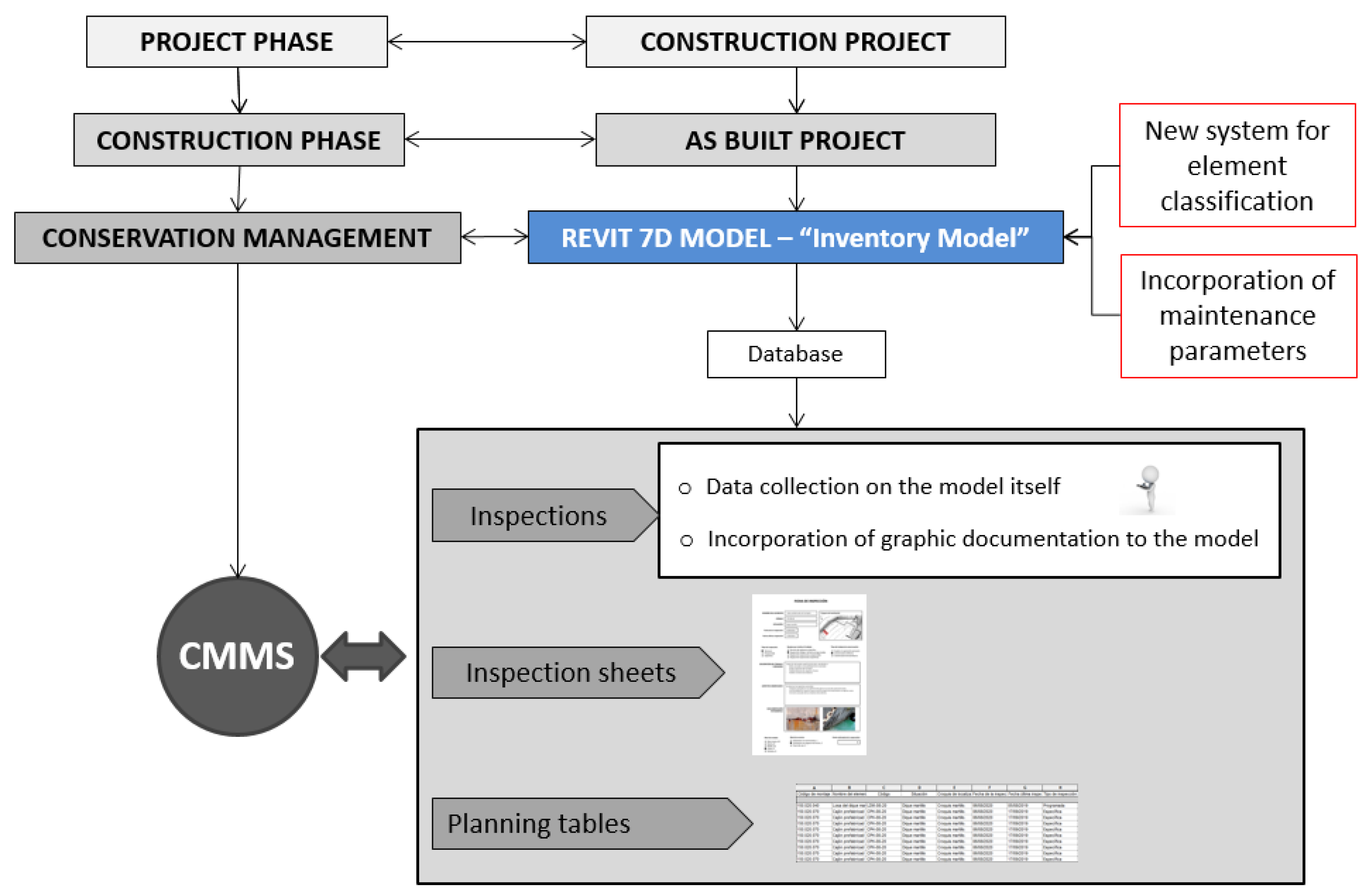
Figure 2 shows the main steps that have been followed for the application of BIM in the management of infrastructure maintenance, differentiating between design, construction, and operation phases. This method proposal has been essential for this research, being the foundation of the study. For all the phases, it is essential to create a database from the design phase to be used during construction and operation phases. It must be considered that some of the defined phases already existed without the application of the BIM method, so the workflow will remain almost the same, but will be developed in a different way due to the different philosophies of both methods. The application of this method will result in a single 3D model of the infrastructure in which all the information necessary to carry out the conservation management of the infrastructure will be collected.
Table 1 describes in a simple way the main advantages and disadvantages of the BIM method in comparison to traditional methods, so decision makers can have the all the information to use one method or other.
Next, the phases to follow in the application of this new conservation management method in port infrastructures are briefly explained, this proposal being key in the future development of BIM for the operation and maintenance of port infrastructures:
Phase 1: Construction project. Modeling in Revit of the construction project (project phase).
Phase 2: “As-built” project. Updating of the construction project with the data of the project built in the construction phase. In this step, the “as-built” model is generated, which acts as an “inventory model” and is the point from which to start working in the infrastructure exploitation phase.
Phase 3: Incorporation of new maintenance parameters into the model. In this phase, a series of parameters associated with each of the inventoried elements are incorporated into the model. These parameters basically consist of all the data that are recorded for each element in a conventional maintenance inspection.
Phase 4: Inspections. One of the objectives that this new method aims to achieve is to be able to take data from inspections directly from the Revit model. Once in the port, the 3D model could be accessed from a tablet, and the data collected directly on the model, filling in all the parameters entered in Phase 3, in the same way as a conventional inspection sheet would be filled out. Graphical information could even be collected, taking photographs of the defects found, and associating them directly with the corresponding model element.
Phase 5: Generation of inspection files. In this phase, the inspection sheets in PDF format are generated and entered into the model. It is proposed that these inspection sheets be incorporated into the Revit model as drawings, with a specific numbering.
Phase 6: Planning tables. This phase consists of obtaining data from the model. To do this, schedule tables must be generated. The planning tables allow professionals to view in an orderly way, through filters, all the information required from the model.
Phase 7: Data extraction from the model for CMMS. From the generation of the maintenance planning tables, the necessary information is extracted for its incorporation into the specific maintenance management programs currently used.
Next, some details of the previously described phases are given. The generation of the “as-built” model must begin with the search for the cartographic data of the environment in which the project is located (orthophotos, topography, bathymetry, etc.), to contextualize the infrastructure and be able to carry out a correct georeferencing of all the elements. With the cartographic information, an identical or very similar topo surface to the existing one is generated in Revit. There are different possibilities to model the existing topography: (a) import from other applications, such as ArcGIS; (b) from contour lines in DWG (DraWinG) format; (c) manual modeling using coordinate points; (d) from CAD to Earth using a surface taken from Google Earth; (e) from other data sources such as the National Geographic Institute or port authorities.
Once the topography has been modeled, the modeling process can be done in two different ways. The first one is to model it in two-dimensional projections. This type of modeling consists of creating a 3D model from 2D plans of the infrastructures (floors, elevations, sections, etc.), generally existing DWG plans. In this case, the model is created by incorporating these planes in Revit, which will serve as a drawing template. Each template is placed in the view and at the corresponding elevation (which will facilitate the georeferencing of the structure), filtering the drawing to display only the necessary information from the 2D plan and enabling a cleaner job. Once the templates have been entered, three-dimensional modeling is performed by extrusions of the two-dimensional drawing and by using BIM objects and families to achieve a more detailed model.
The second way is to model from three-dimensional data. This is modeling from point clouds or meshes that can be obtained using the devices described below in a very simplified way: (a) topographic devices, carrying out the survey of point clouds by means of a total station that carries out measurements from a fixed point. It is a simple job, but expensive in terms of time and budget; (b) laser scanner, a device whose operation is like that of a total station, but it moves automatically, collecting millions of points in each data collection, but the cost of the device is high; (c) photogrammetry, the operation of this technique being based on taking pictures of the element to be modeled, to create point clouds from them; to use this system, specialized personnel in photography are required, but they can obtain very good results.
It is important to bear in mind that the construction project model must be updated to obtain the model of the project actually executed (“as-built” model), which is the one with which it will be possible to carry out the management of infrastructure conservation. This model will serve as an “inventory model” for the management of port maintenance. For this, all the elements of the model must contain, in the form of parameters, a series of properties that allow for ordering and classifying all the relevant data. These properties must be at least: the name of the element, the identification code of the element, and the assembly code according to the Puertos del Estado Element Classification System.
A fundamental element in the information management of the models made with the BIM method is the element classification system. Revit elements have a built-in parameter known as the assembly code. This code consists of a method to organize the information of the model, based on functional elements of the model or parts that make up the infrastructure [
42].
This classification system will be applied to the model to group the information of each of the elements in an organized and logical way. Currently, there are different systems for classifying elements. At the national Spanish level, the GuBIMClass Classification System is available. This system came to light in 2017 and was designed for application in the field of construction (equipment, infrastructures, and facilities) in Spain. It is a living document that is currently working on increasing the number of assembly codes [
43]. At an international level, the most used element classification systems are Omniclaas, Uniclass 2015, and Uniformat.
However, none of them has a sufficient degree of development to classify the entire set of elements that may come into being in a civil work, much less include the elements that make up port and maritime works.
The BIM Guide of Puertos del Estado includes, in its Annex 2 “Element Classification System”, a proposal for the alphanumeric classification of elements of port infrastructure [
44]. What is proposed in this research is to carry out an extension of this classification system of elements of the BIM Guide of Puertos del Estado. In this extension, the new elements of this type of maintenance management model include “pathologies”. The main and most representative pathologies that can occur in this type of infrastructure were analyzed in the first phases of this research.
These new parameters have been classified alphanumerically depending on the type of work or element to which they belong, following the coding established by Puertos del Estado.
Table 2 shows the proposal to expand the classification system of the State Ports BIM Guide.
As recommended in the BIM Guide of Puertos del Estado, for all those elements that are not included in the classification or that are not exclusive to maritime work, the use of the GuBIMClass Classification System is recommended. Likewise, all these factors must be specified in the BEP.
Once the model has been generated, it is necessary to incorporate a series of parameters into the model to include the general information of the inventories. These parameters must be included in the BEP and added to each corresponding element of the model. The parameters are one of the most important parts of Revit objects, since they are the ones that contain all the information of each of the elements. The parameters assigned to each element can be seen in the element’s properties tab. In this case, a series of parameters will be assigned to the elements of the model, to contain the information regarding their state of conservation. For this, the elements that are defined are, basically, those corresponding to the data to be filled in in a conventional maintenance inspection sheet. The choice of these parameters was made based on the recommendations established in the guide “Conservation Management in the Port Environment” [
31,
32] and in the “Standard Practice Manual for Underwater Investigations” [
30], being the minimum amount of data that an inspection sheet must contain.
Next, each of the parameters included in the model are defined: (a) name of the element and associated identification code; (b) situation, with the indication of the relevant infrastructure to which it belongs (for example: spur breakwater, dock, etc.); (c) localization map, with the image that allows visualization of the approximate location of the element in a sketch of the port; (d) inspection sheet, with the image of the inspection sheet filled in with all the data; (e) date on which the item’s inspection is being performed; (f) date the item was last inspected; (g) indication of the type of inspection to be carried out. The types of inspections are defined based on the provisions of the “Standard Practice Manual for Underwater Investigations” [
30]; (h) the work team that will carry out the inspection; (i) the type of conservation work to be carried out in the port, which can be of three types; (j) the detailed description of the work to be carried out during the inspection and the aspects to which special importance will be given; (k) detailed description of the status of the item and the anomalies that occur in it; (l) photographs showing the state of the elements or the defects detected in the inspection; (m) state level represents the situation of a certain element at a given moment and is based on parameters that must be previously defined in the port’s conservation management system (it aims to give an idea of the health status of the elements of a port through five predefined levels: very good, good, average, poor, ruined); (n) the service level, a coefficient that serves to measure the attention given to the user, as well as the way in which those responsible for port maintenance react, in terms of speed and efficiency, to the different problems that may occur in the installation (three levels can be established for its definition: unrestricted use, use with some restriction, and out of use); (o) image of the inspection file filled in with all the previously mentioned data; (p) specific surveillance service and scheduled routine work equipment. This is the team that carries out routine inspections at the foreman level; (q) the team of scheduled inspections (team made up of specialized personnel who are normally part of the port maintenance team in question); (r) specific inspections team (in the event of exceptional circumstances that require resorting to a specific inspection. Usually it is a team of outsourced personnel).
According to the type of conservation work, the following can be found: (a) help with port operations (all those activities necessary for the port to function at the established service levels); (b) ordinary conservation (all those conservation works designed to extend the useful life of the elements of the port); (c) extraordinary conservation (all those activities necessary to carry out the repair of an element of the installation).
Thanks to new technologies, the model can be viewed on portable devices and tablets and can even use virtual and augmented reality. One of the objectives of this new method is for the data collection in the inspections to be carried out on the model itself and not on paper, as has been done to date, saving time and resources. The idea is that the inspections are carried out with a tablet from which the edition of the Revit model can be accessed. The use of tablets to manage the Revit application can be somewhat uncomfortable when working with the graphical interface of the software to model or design. However, since the objective is to introduce alphanumeric data to the parameters of the selected elements, this can be considered a very advantageous solution.
Another possible option is to access the Revit model by remotely connecting the tablet to a computer that contains the program, making it possible for the remote computer to run the program and not the tablet itself. In this way, once in the port, the operator will take the data directly on the Revit model, filling in all the parameters mentioned in the previous section, in the same way that the inspection form would be filled in in the conventional way. With this, the data are recorded at that moment and associated with each element to be inspected. In addition, another advantage of this method is the ease of collecting graphic information on defects or breakdowns that appear in the structures, since with a tablet, workers can take photographs of them and link them directly to the element in question in the model.
Once the data are collected in the inspection, all the elements inspected will have associated the necessary information to be able to fill in the inspection sheets. All these files will be included in the model, generating a database of all the inspections carried out at the facility. To do this, it is proposed to create new plans, with a specific name, which include an image of the item’s inspection sheet, as well as a view of the model in which the pathology or pathology-associated defect appears.
The defects and breakdowns that appear in the infrastructures can be represented in the model, to have a global vision of the state of the installation. With this representation, the inspection work is facilitated in the next actions, being able to visualize the pathologies prior to the inspection and knowing what its development has been. This allows for reducing redundancies of information between one inspection and another. The most comfortable way to view all the pathologies added to the model is to create new specific views of them. These views must be named in a certain way to differentiate them from other views in the model. Considering that the program, by default, orders the views in alphabetical order, the following name is proposed: “PATHOLOGY_Identifying code of the element_Type of pathology”; for example: PATHOLOGY_LDM-08-20_Cracking slab.
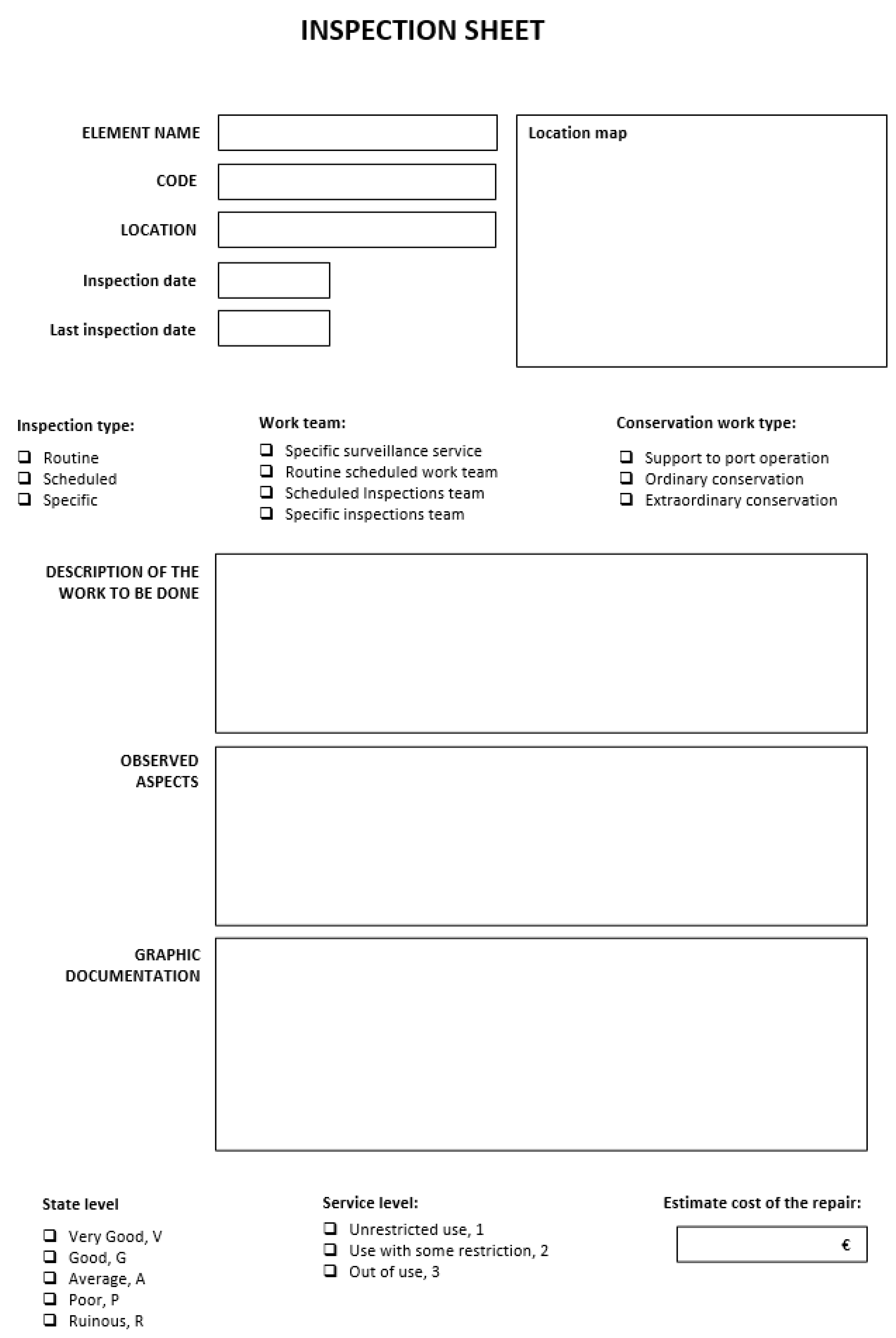
Each inspection file will be included in the model as an image within a plan, with the particularity that these will not be used as plans per se, but as a tool to archive the inspection files within the model. The reason for having to include the inspection cards as images is that Revit, in its 2019 version, does not support the import of PDF files. In the same way as with the views, the plans must be numbered in a specific way, to have control of them and facilitate the data search process. The following is proposed: “FI_Identifying code of the element_Date of inspection”; for example: FI_LDM-08-20_06082020. In this plane, on the left side, the image of the inspection sheet will be inserted, and on the right side, the view of the previously generated pathology. The inspection type sheet used in the application of the method is included in
Figure 3.
At this point, it will have a 7D “as-built” model with a large amount of information, which will allow professionals to carry out the conservation management of the port by extracting and processing the data that are always necessary. For this, they have the planning tables. The planning tables can be considered one more view of the model and as such, they allow for visualizing and extracting all the data that are necessary, for later export to the asset management software used today.
It is important to bear in mind that the information that is modified in the planning tables is automatically updated in the rest of the model and vice versa. Therefore, the tables will also serve to control and edit the model. Schedules are created from the elements of the model and their associated parameters. In this case, the parameters of interest are those related to the maintenance and upkeep of the infrastructures.
Therefore, “maintenance planning tables” are to be obtained. To do this, within Revit, from the View tab, in the Create group, the schedule tables appear. From all the masses of the model, the parameters corresponding to maintenance will be selected, as well as the parameter “Assembly code”, which will be the one that will allow us to filter the masses, to keep only the information that is needed.
In addition to these, more specific parameters can also be added, such as gross volume of items or area measurements. These data can be exported to a database directly coordinated with a CMMS program. In case of the modification of the model data, the results and the analysis are automatically updated.
5. Discussion
5.1. Examples of Typical Pathologies
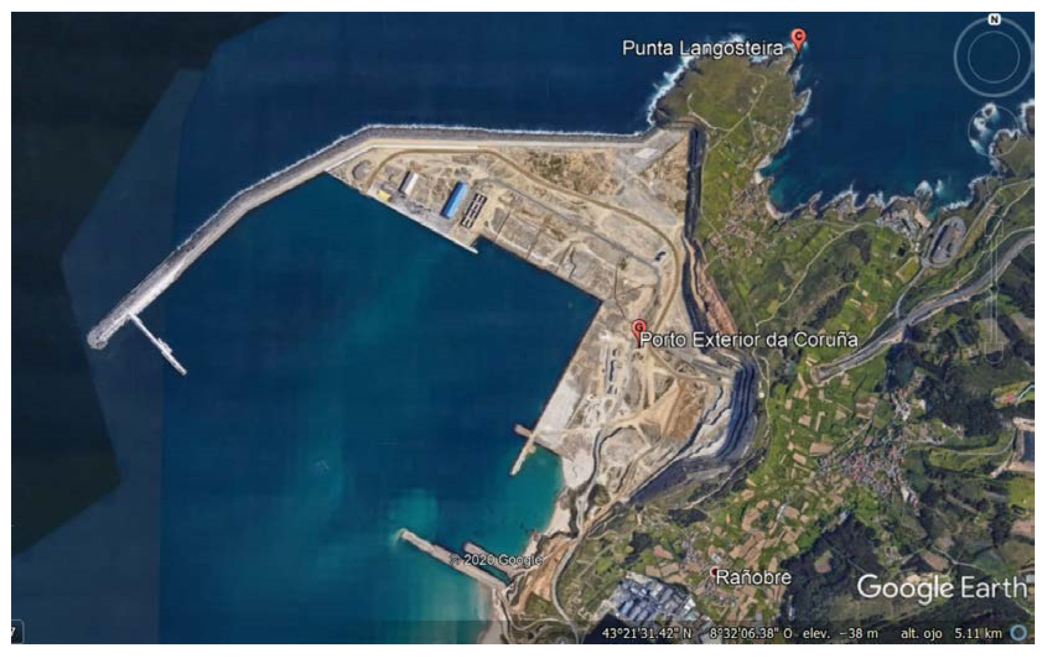
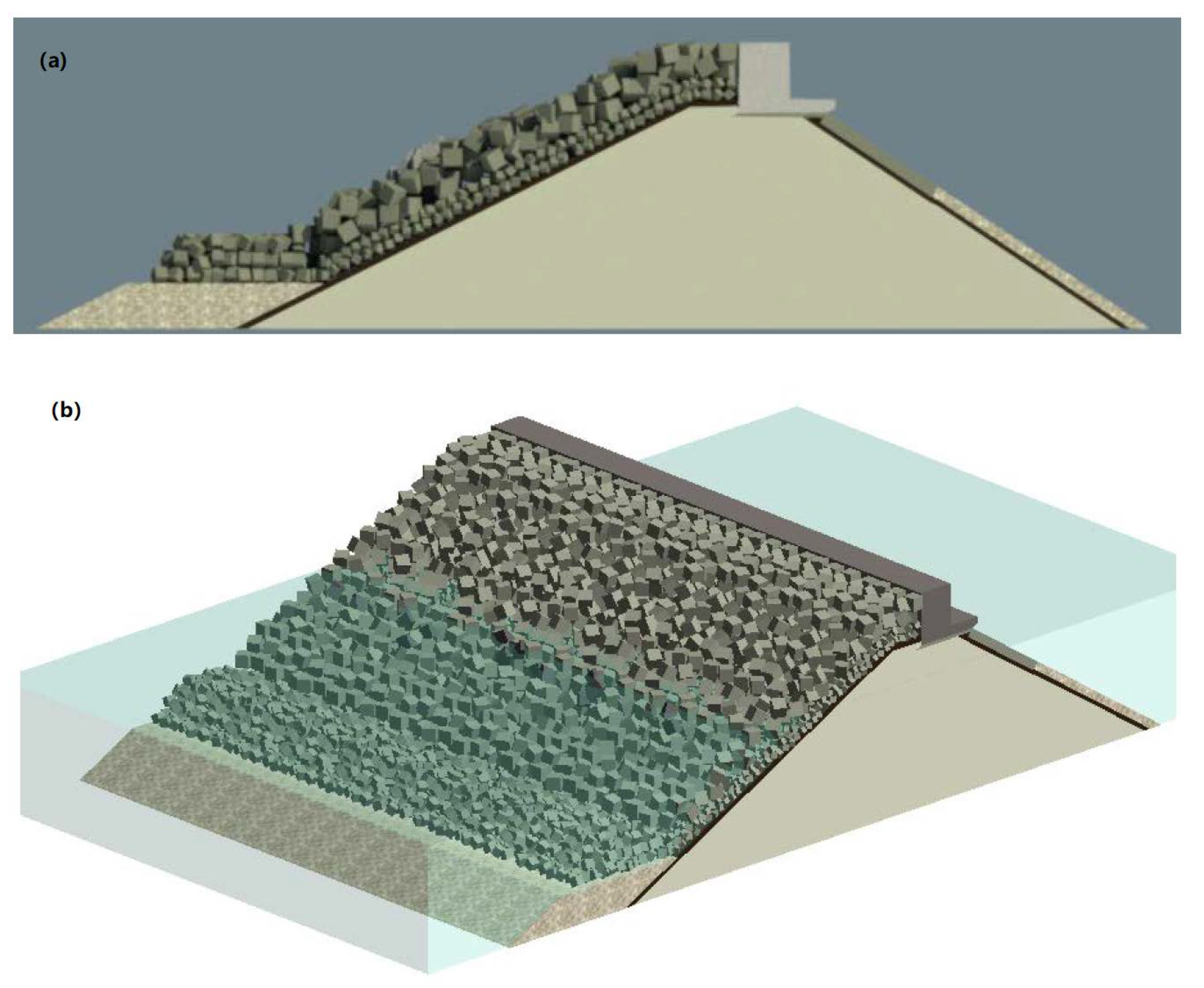
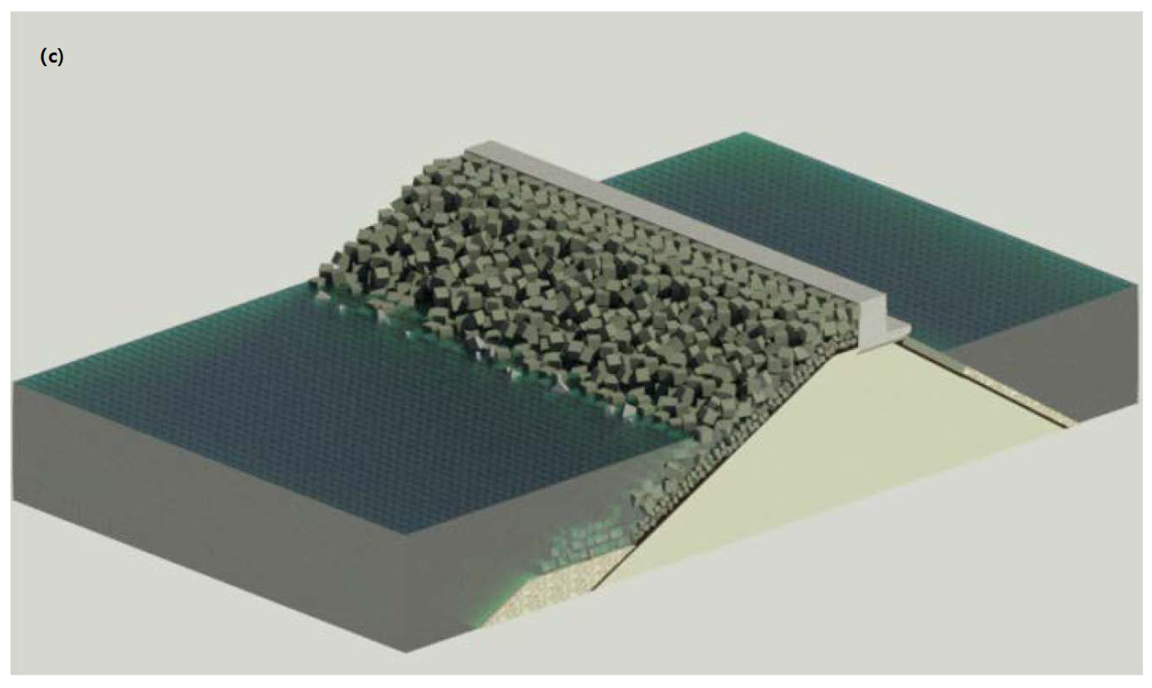
The detail of the port sections selected for modeling in Revit (Version 2019) were entered. The works chosen were the main breakwater (rubble mound section) and the spur breakwater (vertical section), as they are considered to represent the two main and more usual types of breakwater executed in all maritime works, in addition to being those for which data were available for modeling.
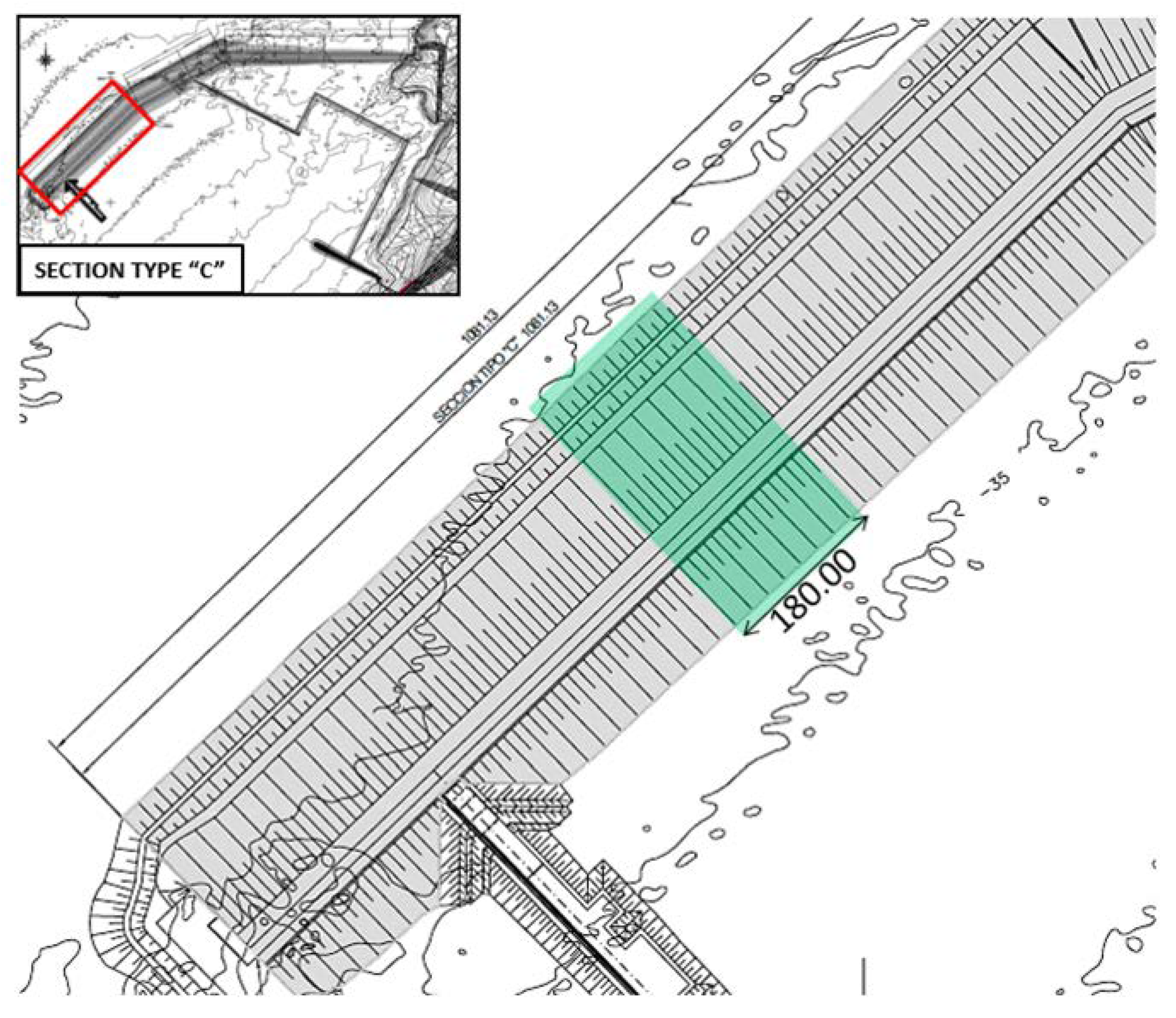
A 180 m section of the main breakwater (Section type “C”) was modeled in Revit 2019.
Figure 4 shows the plan of the main breakwater (Section type “C”).
The modeling was carried out by incorporating an Autocad template of the section of the main breakwater in the Revit program. The elements were created by means of masses in situ and the 3D section was created by means of extrusions of these elements. Likewise, with the aim of creating a more elaborate model that is more faithful to reality, new families of elements were created to represent the 15 t, 50 t, and 150 t concrete blocks that are part of the breakwater’s armor. All elements of the model were classified with the Puertos del Estado Element Classification System. The result of the modeling in Revit can be seen in
Figure 5.
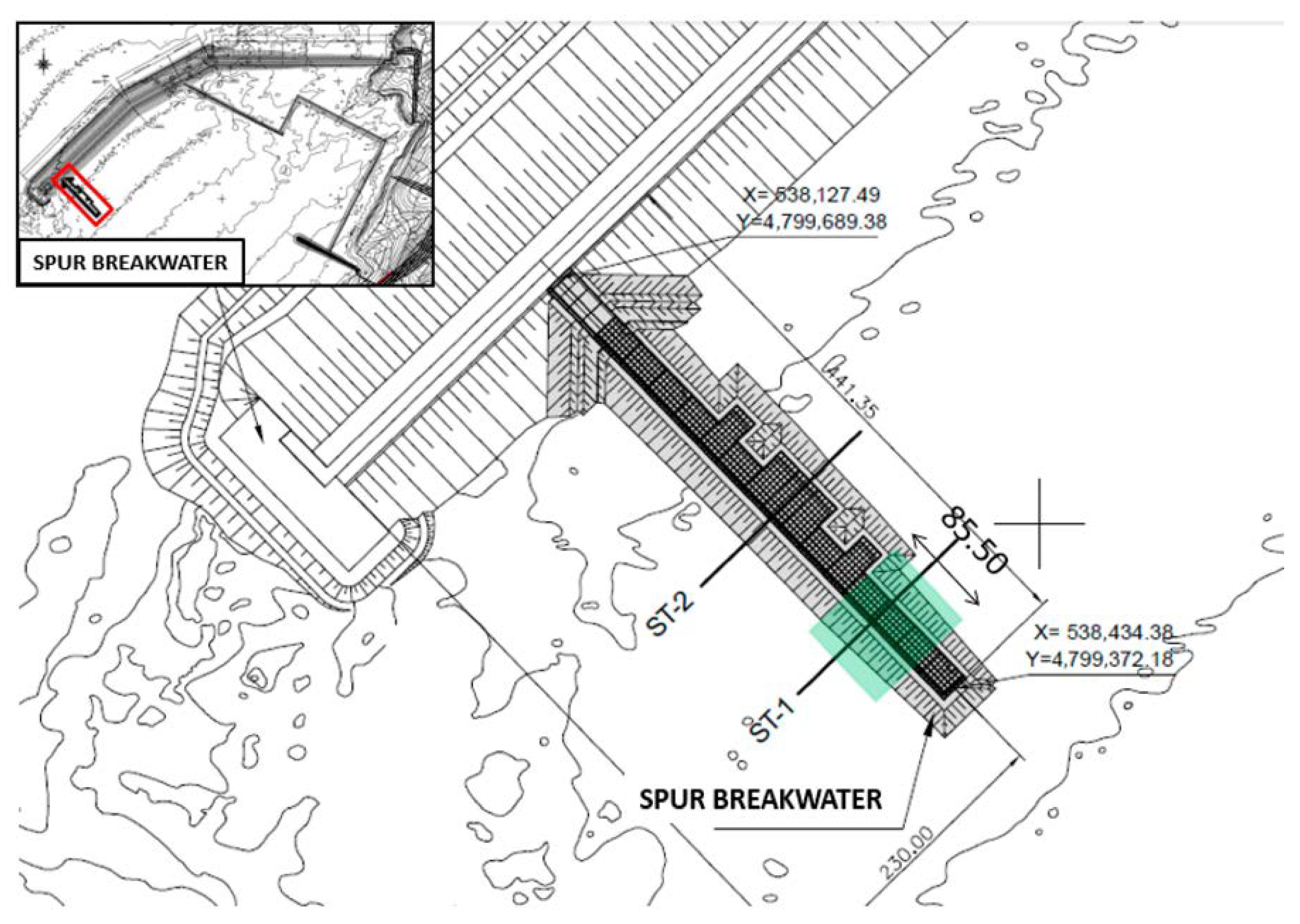
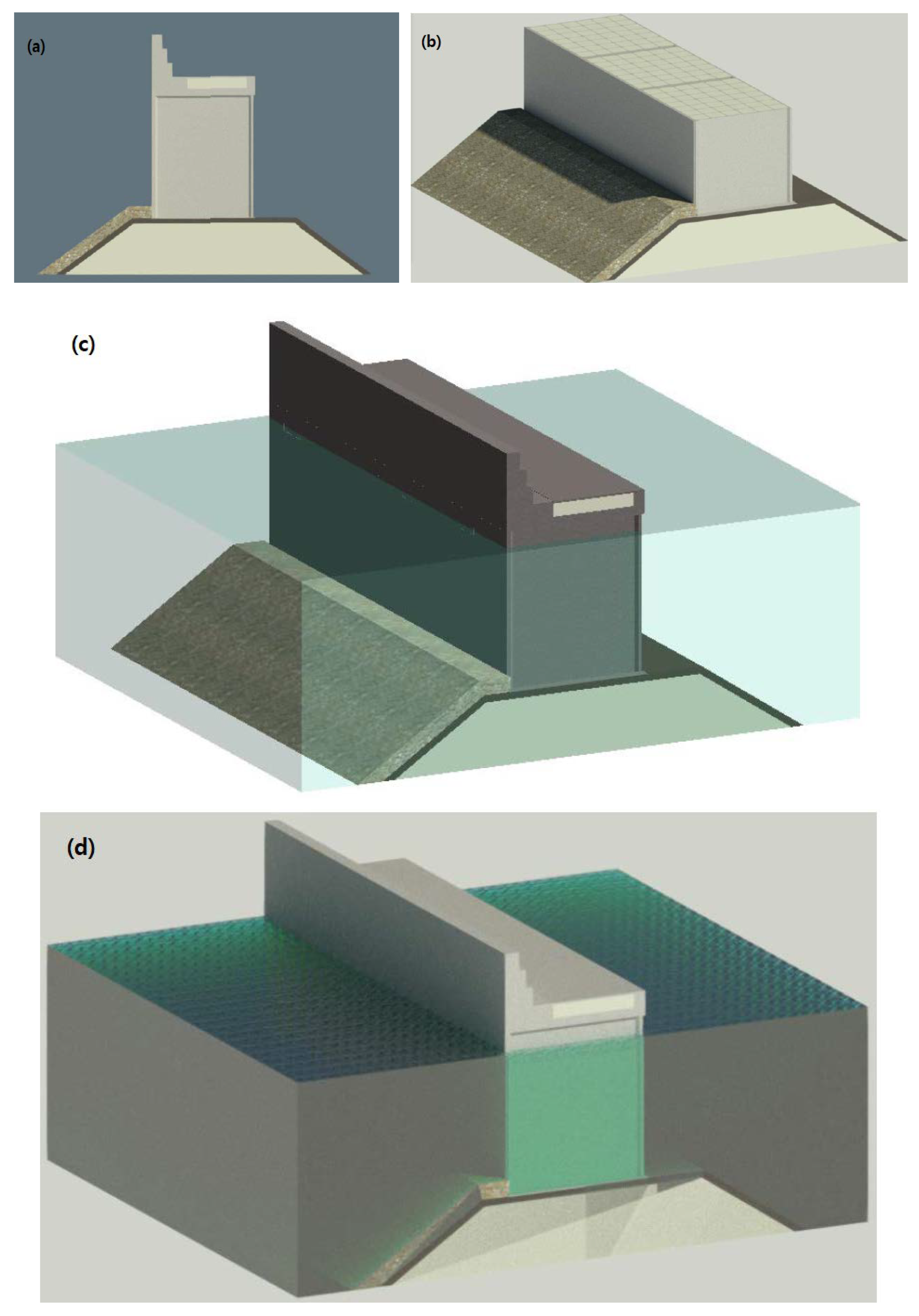
In the same way, an 85.5 m section of the spur breakwater was modeled in Revit 2019.
Figure 6 shows the hammer plan, and
Figure 7 shows the Revit model.
One of the main phases of this new method is the incorporation of a series of parameters, referring to the maintenance and upkeep of the infrastructures, into the elements of the model. All the established parameters were included in the model, in such a way that, when selecting any element of the infrastructure, these parameters and their associated data can be seen. With this step, the “as-built” model is converted into a “facility management”, which includes all the information regarding the management of infrastructure conservation. The information regarding each parameter can be included in the model from the port itself during inspection work.
To carry out this practical case, the hypothesis was made that the infrastructures have a series of defects or pathologies (not real) in certain elements thereof, and the information on the parameters referring to the maintenance of said elements has been filled in, as if filling out an inspection sheet.
Once the inspection data have been collected, the detected defects can be modeled as one more element. These new elements that represent the defects of the structures must be classified as pathologies in the element classification system, assigning them an assembly code from 150 onwards. The pathologies represented in the models are shown below as an example.
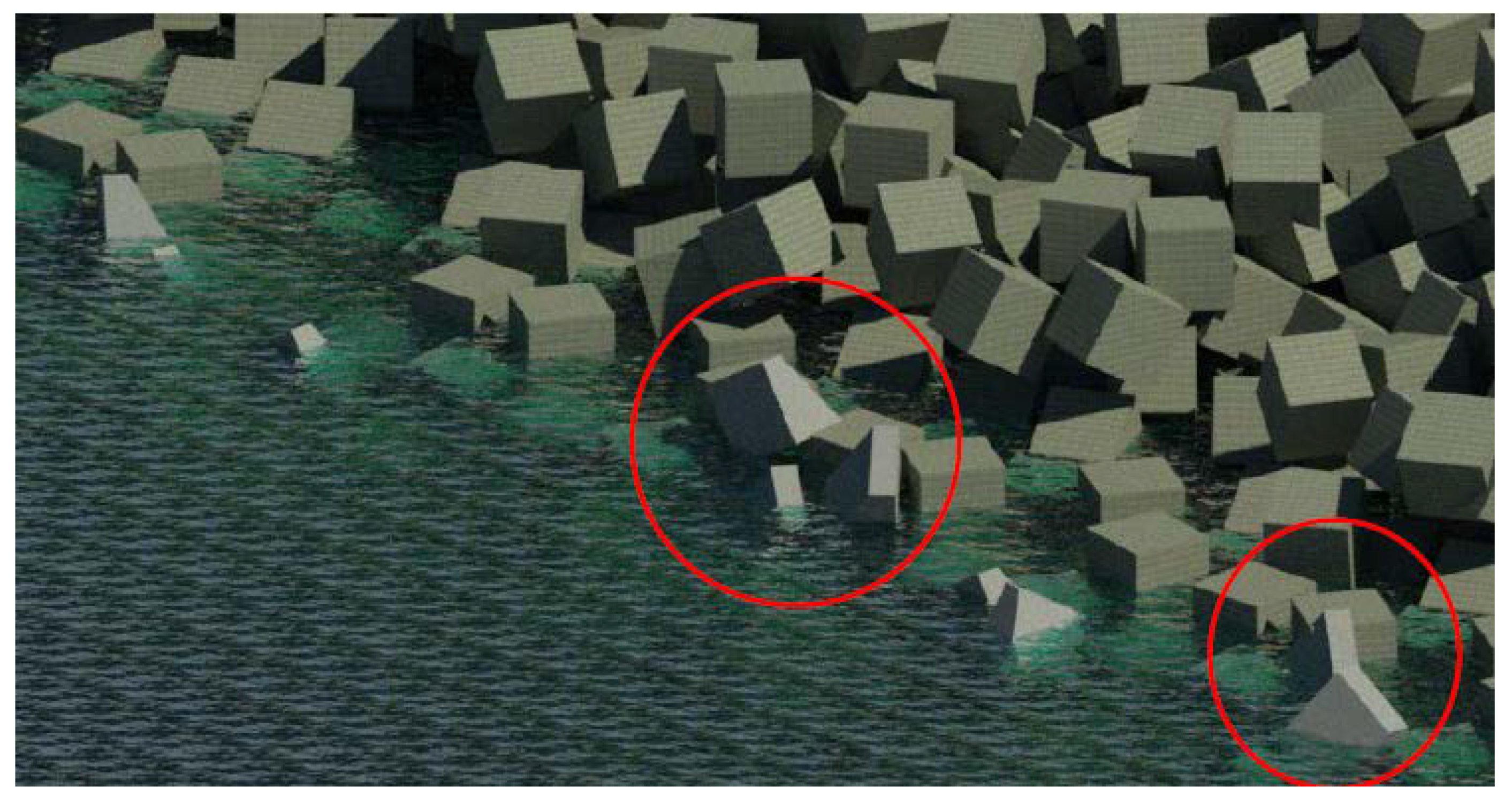
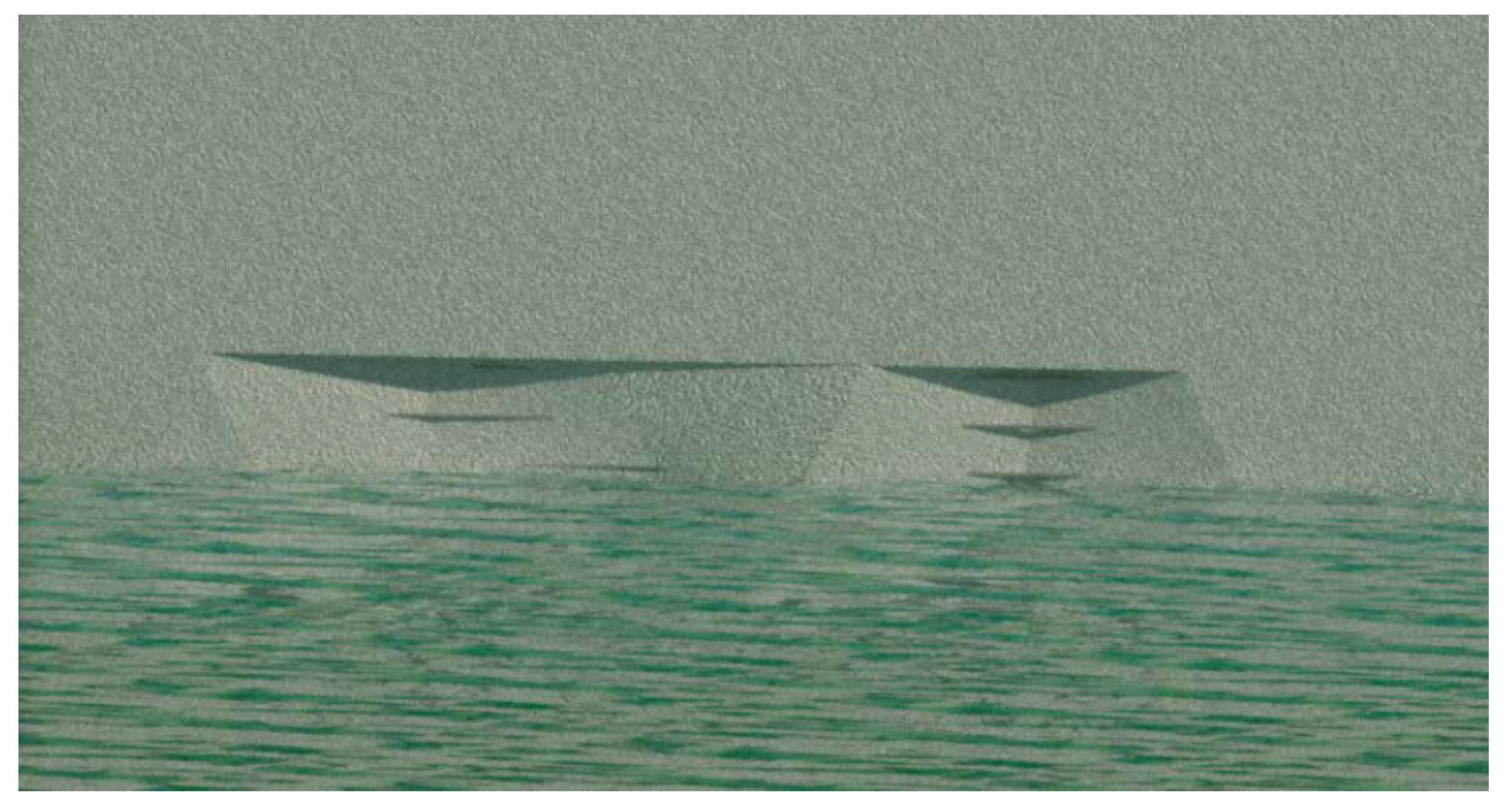
Breaking of 150 t concrete blocks of the armor of the main breakwater is shown in
Figure 8. Assembly code: PT.150.010.020 Armor units breakage.
The presence of cracks and corrosion of the armor of the reinforcement of the caissons that make up the spur breakwater is shown in
Figure 9. Assembly code: PT.150.020.070 Corrosion of the reinforcement of the caissons.
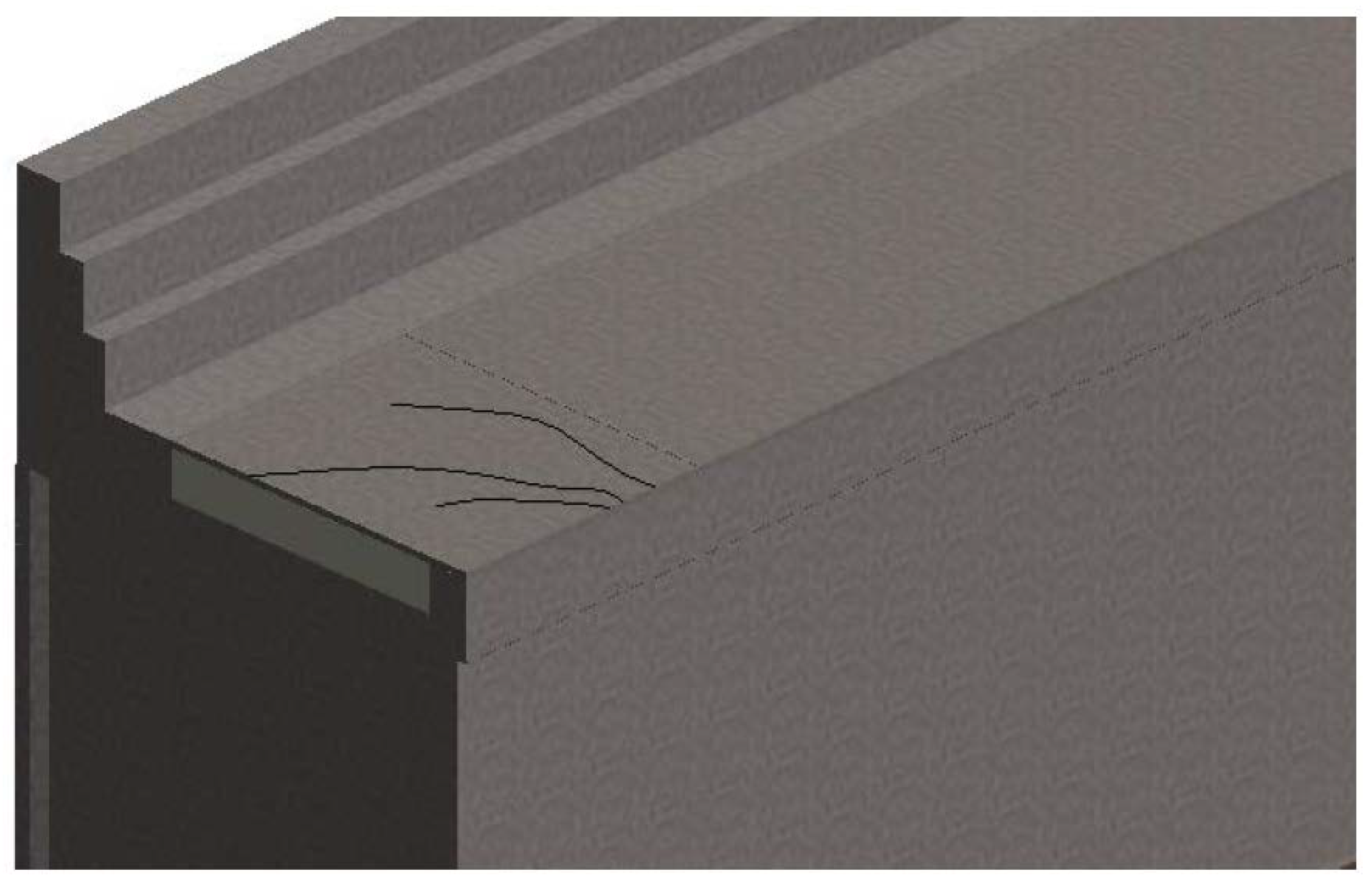
Cracking of the spur breakwater slab is shown in
Figure 10. Assembly code: PT.150.020.040 Cracking of the slab.
With all the information included in the model so far, the inspection sheets can be generated in PDF format for filing in the model. The inspection files must be imported into the model as an image (.jpg) since Revit 2019 does not allow the import of PDF documents. Their filing in the Revit model is done by generating planes, named in a certain way to differentiate them from the rest of the model’s planes:
“FI_Identifying code of the element_Date of inspection”; for example: FI_LDM-08-20_06082020.
On the other hand, specific views of the pathologies modeled in the infrastructures were generated. These views, whose names are as follows, are also included in the plan: “PATHOLOGY_Identifying code of the element_Type of pathology”; for example: PATHOLOGY_LDM-08-20_Cracking slab.
At this point, it has been possible to generate a model with a significant amount of information and that serves as a database for the conservation and maintenance of infrastructures. What is intended at this point is to extract said information, and then use it as appropriate. Generally, the information will be exported to a database to be managed with the CMMS software. To extract the information from the model, the maintenance planning tables were generated.
To generate the tables, all the masses of the model were selected with their maintenance parameters and their assembly code. The program generated a table that contained all the masses that make up the structure of the model, therefore, by applying a filter, only those masses that represent the pathologies are selected, that is, the masses that have an assembly code numbering 150 or higher, leaving only the elements affected by some pathology in the table. The maintenance planning tables extracted from both models and an example of their interpretation are included below.
Main breakwater maintenance planning table: the armor of the main breakwater is in an average state, requiring the replacement of 17 pieces of the armor in the 180 m studied. This would involve, approximately, the removal of a total of 623 m3 of concrete from the exterior armor, for replacement.
Spur breakwater maintenance planning table: the spur breakwater is in an average state, requiring the repair of an approximate area of 430 m2, due to the appearance of cracks and subsidence. The studied caissons are in a poor condition. Approximately 60 m2 of the exterior wall of the spur breakwater have cracks that expose the reinforcement of the caissons.
Ultimately, what is intended to be demonstrated with these examples is the large amount of data that can be extracted from the model through these planning tables. These data must be managed by another type of software since, now, the Revit application is not prepared for such exhaustive data processing.
5.2. Challenges and Lessons Learned
These results are focused on the maintenance stage of a port infrastructure. From a cost life cycle approach, maintenance is acquiring more and more importance, with costs between 25 and 60% [
5,
6]. Considering the aggressive environment of this kind of project, the quality of materials is essential for conservation and maintenance activities [
7,
8,
9,
10]. In this sense, some of the main pathologies caused by such environment are used in the case study (cracks, corrosion, and breaking of concrete blocks).
This proposal and results focus on the maintenance stage, proposing a new method for facility management in ports using BIM that allows for handling the great interconnection and continuous operation of a big amount of information. This problem is marked in the literature as the main issue in facility management in ports [
23,
24,
25,
26,
27,
28]. In this sense, a 3D model with its 7 dimension related to facility management serves as a visual tool plus a database that support decision making during the conservation of any port. This theoretical and practical proposal is a first step, where transport infrastructures are somewhat delayed in their integration of BIM compared with other kinds of infrastructures and buildings [
11,
12,
21].
The BIM method, including facility management as an integrated system as proposed here, allows for the coordination of information and visual issues between all different stakeholders of a port infrastructure with clear operability and connections, solving some problems identified by some authors [
24]. There were not clear classification or codes for the existing elements of marine ports, so an expansion is proposed, with inspection sheet templates and scheduling maintenance activities during the conservation stage. In this paper, the case study is already projected and built. However, with the know-how from the results presented here, BIM technology can be implemented with a greater impact from the planning and design stage to the whole life cycle, as some authors highlight [
45], so the facility management system can have a greater impact from the beginning. Additionally, the facility management system based on BIM allows for the automation of planning the maintenance costs and scheduling the interventions, and serves as a database of all correctives observed during the operations, solving some problems already identified in the literature [
46].
6. Conclusions
While in the architecture sector the use of the BIM method is in a much more advanced state internationally, even in the field of facility maintenance, the civil engineering sector is lagging in this regard, and much more so in the sector of port infrastructures and their maintenance and conservation. In the state of the art, there are some general studies about the use of BIM in ports, but there is not a method to use BIM philosophy in the maintenance of ports, as there is in this case study. Up to now, traditional methods (not BIM) have been used for characterizing the assets, evaluating their state, carrying out the registering of inspection and repairs, etc. The new proposed method created and validated in this manuscript is the main result of this research; this can be used as a tool for its implementation in the maintenance of port infrastructures.
With this research, the numerous studies that exist today on this subject have taken ground, and it is presented as a paradigm shift in the approach to infrastructure maintenance management.
Once this new conservation management method is put into practice, it can be concluded that a correct application of the BIM method in projects can greatly optimize the maintenance and conservation management work of port infrastructures, thanks to the collection of all the information in a single model. Although the case study is a Spanish port, this new method can be useful for every seaport authority worldwide; so, there is not a limitation on its application in any country. It has been proven that this is possible from the creation of a three-dimensional model with the Revit program, in which all the information regarding the maintenance and upkeep of the modeled infrastructures is incorporated. It should be noted that the application of this method requires workers to be trained in this type of tool.
Likewise, the advantages of applying this method have been disclosed. The main benefits it offers are: (a) the three-dimensional representation of the infrastructures in an integrated data environment; (b) the storage of the history of inspections and repairs carried out on the infrastructures; (c) faster and more efficient work processes, thanks to the parameterization of all the elements of the model, allowing the automatic updating of all the data contained in it; (d) collaborative work is promoted, facilitating the exchange of information between the different agents interested in the project, in all its phases; (e) the ease of locating elements and assets of the infrastructures, which allows for greater control and management of all of them; (f) the connection and information exchange between the BIM and CMMS tools, which allows for better planning of the maintenance tasks to be carried out, making it possible to visualize the changes in the 3D model, as well as to consult all the necessary information of an intuitive and simple way; (g) it allows for the abandonment of the information silos of the works of conservation and maintenance of existing structures; (h) although the BIM method is designed for application to new construction projects, all the benefits of its incorporation in the exploitation phase of a project must be considered, even if the effort for its application is greater than if it had been implemented in the design phase.
During the development of this project, certain aspects have been detected that for the moment are not developed and that are beyond the established scope. Therefore, the following lines of work are proposed to be developed in future research: (a) creation of new parametric families that allow for a simpler and more comfortable modeling of port infrastructures; (b) creation of new families that allow for a modeling more adjusted to the reality of the most representative pathologies of this type of infrastructure; (c) to reduce the current disadvantages of BIM philosophy: resistance to change, lack of proven method in most of civil infrastructures, high implementation cost, need for software training, and problems of software interoperability. Constant review of the state of the art of the BIM method is needed since it is a work method that continues to be updated and renewed day by day; (d) integration of the agents responsible for managing the maintenance of port infrastructures in the process of applying BIM to maintenance. In this way, the information that needs to be obtained from BIM will be specifically defined.

 ,
, 


