1. Introduction
Autonomous underwater vehicles (AUVs) are currently recognized as important tools for supporting the exploration of oceans since they can carry a large amount of equipment with a relatively low operational cost [
1,
2]. In addition to oceanic exploration [
3], AUVs are used for inspecting submerged structures [
4], exploring unknown submerged areas [
5], and in military and defense activities [
6], among other applications.
The structural part of an AUV is usually composed of a cylindrical shell housed inside the hydrodynamic hull. The role of this waterproof shell is to contain the electronic devices needed for the AUV mission. Generally, studies on the structural design of this class of vehicles aim to achieve rigidity using a structure as light as possible but able to meet buckling resistance criteria [
7,
8,
9,
10,
11].
In thin shells, buckling failure may occur before the yield strength limit, depending on the geometry (including the influence of geometric imperfections) and material properties [
12,
13]. Nonlinear finite element simulations of imperfect cylindrical shells subjected to a uniform external pressure show that the critical load may be significantly reduced, reaching less than 75% of the value obtained by a linearized buckling simulation of the perfectly cylindrical shell [
14]. The imperfections found in structures may be classified into global or local types: the first ones are related to deviations of the “perfect structure” that extend to a large part of it (e.g., out-of-roundness of the cross-sections or thickness variations that extend along the length of a shell, generalized corrosion of the shell surface, etc.), whereas the latter ones are related to those deviations of the “perfect structure” that are restricted to a small part of it (e.g., small dimples or small indentations on the shell surface, welding defects, small corroded areas, etc.). The role of these different imperfection types on the stability of structures has been studied by several researchers. Nguyen et al. [
15], for instance, studied the effects of small thickness variations on the buckling of cylindrical shells under external pressure. The thickness of the shell was assumed to vary only in the axial direction following a trigonometric function and formulae for the buckling load, which were derived by the combined perturbation and Bubnov-Galerkin methods. Yang et al. [
16] extended this study and presented a unified analytical formulation to predict the buckling load of cylindrical shells subjected to external pressure, considering general axisymmetric imperfections in the thickness.
In the work of Godoy et al. [
17], both reduced stiffness analysis (RSA) and reduced energy analysis (REA) were applied to the buckling analysis of cantilever cylindrical shells, with or without a fixed top roof, and subjected to wind loads. The numerical results were compared with those obtained by a geometrically nonlinear analysis including geometric imperfections, allowing them to show the advantages and drawbacks of both approaches. In order to reduce the computational time in the post-buckling analysis of stiffened composite shells, Liguori et al. [
18] proposed an optimization strategy using a reduced order model (ROM) for the approximation of the equilibrium path. According to the authors, the most interesting aspect of the proposed strategy is that the sensitivity to geometrical imperfections of the stiffened panels could be easily included in the optimization process. In the work of Groh, Avitabile, and Pirrera [
19], focus was also put on the nonlinear post-buckling analysis of composite shells used for shape-morphing in the aerospace industry. By means of two classical problems taken from the literature, the authors demonstrate that the generalized path-following method suits well to modeling morphing structures.
An extension of the Koiter-Newton approach, suited for the buckling imperfection sensitivity analysis of structures, was proposed by Liang, Ruess, and Abdalla [
20] that presented and compared two different modeling strategies to trace the nonlinear equilibrium path: (i) the independent imperfection load (IIL) model and (ii) the imperfection loads based on the sub-loads (ILS). Some examples were used to compare the computational efficiency of both methods with that based on a general purpose finite element software, showing that the proposed approaches were proven to be much more efficient for the buckling analysis of imperfection-sensitive structures.
In the work of Wunderlich and Albertin [
21], a semi-analytic treatment of the field equations that govern the nonlinear static behavior of shells is proposed to derive the relationship between the limit load and the amplitudes and shapes of the so-called ‘worst’ imperfections in a direct way. Among the investigations, the authors analyzed the influence of the material behavior, the boundary conditions, the geometry, and combinations of shells (influence of the connections) in the nonlinear buckling analyses of imperfection-sensitive shells. In other recent work based on the Koiter method, Garcea et al. [
22] used a mixed solid-shell finite element to provide an accurate treatment of the geometrical imperfections in shell structures. The main idea behind the methodology was to correct the linear modes of the perfect structure reduced model by means of additional corrective modes which consider the structural imperfections. A large number of examples, including plates, semi-cylindrical isotropic and laminated roofs, compressed channel sections, cylinders, and frames, are used to demonstrate the validation of the proposal.
In most cylindrical shells subjected to hydrostatic loading, rings are used to increase the structural stiffness, traditionally by welding them externally or internally to the shell. Several works have been presented on the stability analysis of stiffened cylindrical shells in the last decades. Among some relatively recent works related to this topic, Arani et al. [
23] used the Ritz method to determine the critical load values of stiffened cylindrical shells subjected to a general form of axisymmetric lateral pressure and uniform axial pressure. Different kinds of stiffener arrangements were considered by the authors including inner or outer rings and longitudinal stringers as well. The authors carried out different analyses varying either the stiffener arrangement type or the compressive loading form, and their results were compared to those presented by Singer et al. [
24], showing a good agreement in some cases. Based on the reduced stiffness method, Bai et al. [
25] investigated the effects of different stiffness reductions on the stability of ring-stiffened cylindrical shells under hydrostatic pressure. Taking the overall buckling load of a given ring-stiffened cylindrical shell as one of their case studies, the authors compared their numerical results to those obtained by other different methods presented in the literature, including rules produced by classification societies, showing differences between −19% and −36%. Another investigation concerning the behavior of ring-stiffened cylinders subjected to hydrostatic pressure was conducted by Cho et al. [
26], who investigated the residual strength of these structures when damaged by drop testing. The damage process, followed by collapse due to the application of hydrostatic pressure, was simulated using Abaqus software. The numerical results were then compared to experimental test results, showing a good agreement. The authors presented several interesting conclusions linking the energy parameter with the residual strength of the structure.
Other comparisons among experimental, numerical, and analytical results were presented by Cho et al. [
27]. In this case, the authors investigated the failure modes observed in nine steel ring-stiffened cylindrical shells subjected to external hydrostatic pressure. The structural failure modes observed in the tests included: overall buckling, shell yielding, local shell buckling between ring stiffeners, and interactive buckling mode. Almeida et al. [
28] proposed a design methodology using finite elements for buckling optimization of composite cylinders subjected to axial loads, and showed that the optimized cylinders presented non-symmetrical patterns of buckling due to geometrical imperfections. According to Radha and Rajagopalan [
29], failure of stiffened shell structures occurs, in most of the cases, due to elastic buckling. However, for some combination of shell-stiffener geometries and material behavior, the structure may fail by inelastic buckling. Accordingly, the authors presented three different approaches to investigate the ultimate strength of a ring-stiffened submarine pressure hull: the Johnson-Ostenfeld inelastic correction, the imperfection method, and the finite element approach. The differences obtained by the three methods were quite small (about 2%) for the case of overall buckling failure. It is also worth mentioning the contributions due to MacKay and his collaborators concerning the analysis of externally pressurized hulls in different aspects (see, e.g., References [
30,
31,
32,
33]).
Another alternative to increase the shell buckling strength involves the use of corrugated shells, as presented by Ross and Humphries [
34] and Zhang et al. [
35]. In these studies, the authors analyzed several corrugated cylindrical shells subjected to uniform external hydrostatic pressure and compared the experimentally obtained results with finite element results. The use of stiffeners or corrugated shells indeed increases the shell rigidity and the buckling pressure of the stiffened shell, but AUV dimensions are much smaller when compared to those found in submarines, and the traditional reinforcement using welded stiffeners or corrugated shells would cause a significant reduction of the inner space. Moreover, the welding or corrugating processes may produce imperfections and increase manufacturing costs, which may hinder the development of a small unmanned underwater vehicle.
On the other hand, the adoption of a sliding platform to place the electronics and other devices inside a pressure vessel is common in practice [
36]. Differently from the welded stiffeners, the sliding platform is not rigidly attached to the shell. However, this work shows that it can provide a good increase to the buckling pressure of an AUV since it limits the radial displacements at the contact points between shell and platform. To the best of our knowledge, the structural role of such sliding stiffeners has not been previously analyzed for a shell under hydrostatic pressure. Using a similar stiffened geometry to that adopted in this work, Xiang et al. [
37] proposed the analysis of a ring-supported shell, but submitted only to an axial compression loading. Moreover, the rings were not allowed to deform, which was quite a limiting assumption.
To show the advantages of using the sliding stiffeners concept to improve the buckling resistance of AUV cylindrical shells, this work presents a comparative buckling analysis of the shell of an existing AUV considering three different scenarios: (i) analysis of the unstiffened shell, (ii) analysis of the shell with conventional (welded) ring stiffeners, and (iii) analysis of the shell with sliding stiffeners.
The work is organized as follows.
Section 2 presents analyses of an unstiffened and perfect shell using both analytical formulations and a finite element modeling so that a lower bound for the critical pressure is obtained in this first case. In
Section 3, the critical hydrostatic pressure is calculated again for the same perfect cylindrical shell, but now reinforced by four small ring stiffeners equally spaced along the shell length. Appropriate analytical formulations and a new finite element modeling are used to estimate the values of the critical pressure in this second case. In
Section 4, a finite element modeling based on a shell stiffened by the structural elements of a sliding platform (not welded to the shell) is carried out to show the effective benefit of this new conceptual design in increasing the critical pressure of the vessel. In
Section 5, geometrically nonlinear analyses considering imperfections in the AUV shell are carried out to check the sensitivity of the last shell design, presented in
Section 4, to realistic geometric imperfections caused, e.g., by accidental loads that induce an out-of-roundness in the shell. Finally, the main conclusions and some suggestions for future works are presented in
Section 6.
2. Analysis of the Unstiffened Shell
The objectives of this section are: (i) to estimate, via analytical formulations and finite element models, the order of magnitude of the buckling pressure for the perfect unstiffened shell, (ii) to carry out convergence analyses to obtain an adequate mesh size for the finite element modeling, and (iii) to obtain a lower bound value of the critical pressure for the shell in this condition.
Relatively good estimates for the critical pressure of an unstiffened perfect cylindrical shell can be obtained using analytical formulations taken from the literature. Subsequently, some of these formulations are presented and used to estimate the order of magnitude of the critical hydrostatic pressure of an existing AUV designed by the Unmanned Vehicles Laboratory at the University of Sao Paulo (see Barros et al. [
38]). Five analytical formulations were selected:
The Von Mises simplified equation (see, e.g., Windenburg and Trilling [
39], Donnell [
40], Timoshenko and Gere [
41] and Allen and Bulson [
42]).
The Von Mises complete equation (see Windenburg and Trilling [
39]).
The Tokugawa equation (see Windenburg and Trilling [
39]).
The U.S. Experimental Model Basin equation (see Windenburg and Trilling [
39]).
The Kendrick equation (see MacKay [
30]).
The Von Mises simplified equation (see References [
39,
40,
41,
42]):
The Von Mises complete equation (see Reference [
39]):
where,
The Tokugawa equation (see Reference [
39]):
The U.S. Experimental Model Basin (DTMB) equation (see Reference [
39]):
The Kendrick equation (see Reference [
30], page 19):
In all these equations,
stands for the critical buckling pressure,
E and
ν are the elastic constants of the material (Young’s modulus and Poisson’s ratio, respectively),
h,
R, and
L are the main shell dimensions (thickness, mean radius, and length, respectively), and
n is the number of complete lobes (or waves) in the circumferential direction. These equations can also be presented in terms of the non-dimensional critical pressure (
) and other non-dimensional geometric parameters, defined by:
It is also important to highlight the assumptions behind the presented formulations, which are:
The shell is subjected to a uniform hydrostatic pressure, i.e., both lateral pressure and axial load are considered.
The material of the shell is homogeneous, isotropic, and has a linear-elastic behavior.
The formulas are valid for shells whose length is shorter than the critical length (
Lcr) given by (see, e.g., Reference [
39]):
The boundary conditions are those of a simply supported shell at both ends, which means (see, e.g., Hoff and Soong [
43]):
Equations (1)–(5) were applied to the cylindrical shell of an existing AUV (see Reference [
38]) made of aluminum (5456-H111) (
= 70.3 GPa,
= 230 MPa, and
= 0.33) with dimensions
= 840 mm, R = 97.175 mm, and
= 6.35 mm. The critical length calculated according to Equation (10), in this case, is
1191 mm, so that
0.705, i.e., the AUV length is, in fact, shorter than the critical length. The other non-dimensional parameters given by Equations (7)–(9) for the AUV dimensions were (the subscript ‘
’ stands for ‘vehicle’):
Another important non-dimensional parameter presented by Windenburg and Trilling [
39] is the thinness factor, which is indicative of the mode of failure to be expected. This parameter depends not only on the two geometrical parameters
λ and
ζ but also on the material parameters
E and
. It is given by:
According to Galambos [
44], elastic instability is likely to occur for
K > 1.2, plastic instability is expected for 0.8 <
K < 1.2, and yielding for
K < 0.8. Substituting the previous numerical values of the AUV, it results, in the present case, as
1.547. Thus, an elastic instability is likely to occur for the unstiffened shell and use of Equations (1) to (5) to estimate the critical buckling pressure is acceptable.
The associated curves for the non-dimensional critical buckling pressures
, for the fixed value
, are presented in
Figure 1 (in the range
) and
Figure 2 (in the narrower range
, which still contains the vehicle ratio
). The numerical values obtained from Equations (1)–(5), as well as the related non-dimensional
values, are shown in
Table 1 for comparison.
The obtained results using the analytical formulations show that:
- (i)
The most conservative value for the critical buckling pressure is the one given by the Von Mises complete equation (Equation (2)), which provides a result very close to Kendrick’s equation (Equation (5)).
- (ii)
The least conservative value for the critical buckling pressure is the one given by the Von Mises simplified equation (Equation (1)).
Then, as the first step towards a more reliable determination of the critical buckling pressure of cylindrical shells subjected to external pressure using finite element analyses, some results of linear buckling analyses of the described unstiffened shell are presented. These analyses were carried out using the software Ansys (version 2019R2). The boundary conditions at the two ends of the shell were assumed as simply supported, consistently with those assumed in the previous analyses, and a uniform unitary hydrostatic pressure was applied all over the external surface of the shell. The finite element used in all the analyses was shell181, a four-node element with six degrees of freedom at each node (translations in the local x, y, and z directions, and rotations about these same directions). This finite element is suitable for analyzing thin to moderately thick shell structures.
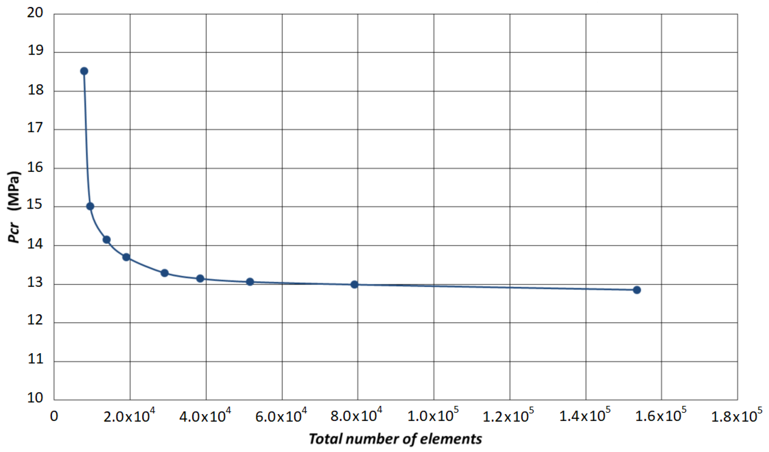
Figure 3 shows a convergence analysis using an increasing number of shell181 elements in the modeling of the unstiffened shell.
According to the numerical results presented in
Figure 3, a critical pressure of about 9.1 MPa was achieved using the proposed finite element model (FEM).
Figure 4 shows the eigenmode and the corresponding eigenvalue (load multiplier = 9.093) obtained using a linear buckling analysis, with it being evident that
n = 2 is the number of half semi-waves obtained in this case, which agrees with the analytical formulations. About 135,000 shell elements were used in the most refined mesh to obtain the lowest eigenvalue (see the picture of the mesh used in this case in
Figure 5.)
Comparing the FEM result with those obtained via analytical formulae, we noticed that deviations were not significant: using the FEM result as the reference value, the highest deviation was about 19.4% (if compared to the complete Von Mises formulation) and the smallest one was 2.6% (if compared to the simplified Von Mises formulation). Compared to the mean value presented in
Table 1, the deviation is about 12.4%.
It is worth mentioning that, since the analytical formulations are based on trigonometric functions that approximate the real buckling modes, small deviations of such an order of magnitude are quite acceptable. For a comparison purpose, the three first eigenvalues for the three shell designs presented in this work will be shown further (see
Section 4, Table 4).
3. Analysis of the Conventional Stiffened Shell
In this section, it is assumed that a conventional stiffened shell (that means, a shell with regularly spaced ring stiffeners welded to it) is subjected to an external and uniform hydrostatic pressure.
Figure 6 shows the basic geometry of such a schematic stiffened shell and
Table 2 provides the numerical values which have been considered in this case study, with four regularly spaced ring stiffeners placed along the AUV length. The material of the stiffeners is the same as the shell, whose elastic properties are presented in
Section 2.
The following expressions given by Equations (16)–(18) may be used to represent a lower bound for the empirical interframe collapse pressure and are accurate to within 1% of the lower bound curve used in BS5500 (see, e.g., MacKay [
30]).
where
is Kendrick’s version of the Von Mises collapse pressure, which is calculated according to Equation (5) using
as the unsupported length between stiffeners (instead of
LB, which is the total length of the AUV shell), and
represents the externally applied pressure that makes the stress measured in the circumferential direction, at the mid surface of the plating and midway between stiffeners, reach the yield stress (
) of the material, and is given by the expression (see MacKay [
30], page 23):
The parameters
and
are given by (see, e.g., MacKay [
30] and Kendrick [
45,
46]):
and,
where,
= (radius to the extreme fiber of frame flange),
(cross-sectional area of frame).
After substituting the numerical values related to the present case study in the presented formulae, one obtains:
Therefore, the ratio
provides:
Then, using Equation (17):
That is the critical buckling pressure related to the interframe collapse of the presented stiffened shell.
Figure 7 shows the two branches of the curves represented by Equations (16)–(17) and the numerical values for the pair (
,
) obtained for the present data.
Besides the interframe collapse, the generalized collapse of the ring-stiffened shell is another failure mode that must be considered. In this case, the collapse pressure may be estimated by the following equation:
where the shell term
represents the contribution of a similar unstiffened shell, i.e., without ring frames, to the total collapse pressure, and
represents the contribution of a single ring frame to the total collapse pressure. According to the Bryant equation, the parcels
and
are respectively given by (see, e.g., MacKay [
30], Galambos [
44], Lunchick [
47], Cho et al. [
27]):
However, use of Equation (20) to obtain
, for the present case study, results in
1.53 MPa, which is not a correct value considering either the analytical results obtained with other equations proposed for the unstiffened shell (see
Table 1) or the finite element result obtained for the unstiffened shell (according to which
9.1 MPa). Thus, instead of using Equation (20) to determine
, a better estimate of this parcel is given by Equations (1)–(5), whose results do not deviate so much from each other and are closer to the finite element result obtained in the previous section. Regarding the parcel
, after following the formulation provided by Galambos [
44] to obtain the inertia
(effective moment of inertia about the centroid of a section comprising one single stiffener plus an effective width,
, of the shell), one obtains for the present case:
and
Table 3 shows, in the third column, the estimated values for the critical buckling pressure of the conventional stiffened shell using the five formulations presented in
Section 2. The mean value obtained with the analytical formulations is 11.42 MPa, which represents a 43% increase in the mean value obtained previously for the unstiffened shell. Since all values presented in
Table 3 are below the critical buckling pressure for interframe collapse, a generalized buckling is expected to occur for this conventional stiffened shell.
Regarding the finite element modeling for this conventional stiffened shell design, shell181 elements were used again to represent the shell, whereas three-dimensional (3D) solid elements (solid187) were chosen to represent the stiffeners, due to their low aspect ratio. The boundary conditions were kept the same as before, according to those presented in Equation (11).
Figure 8 shows the numerical results obtained by the convergence analysis that was carried out, resulting in a critical buckling pressure of 11.3 MPa for the conventional stiffened shell. This value was obtained using about 125,000 elements in the finite element model with the most refined mesh.
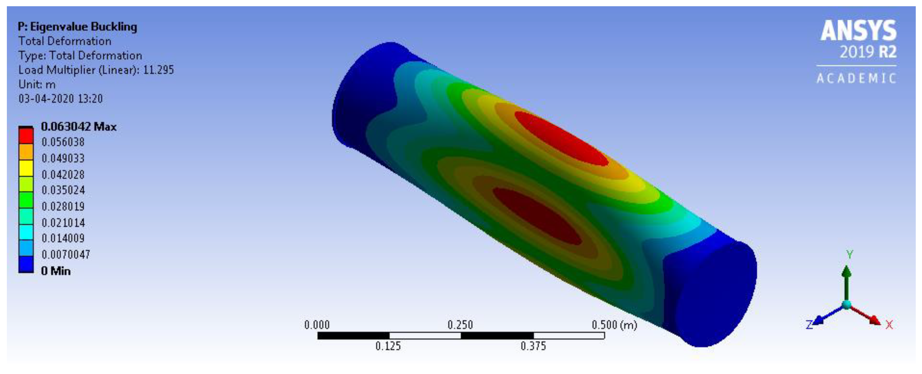
Figure 9 shows the eigenmode and the corresponding eigenvalue (load multiplier = 11.295) obtained using a linear buckling analysis with Ansys (version 2019R2), showing that a generalized buckling mode is obtained in this case (as also predicted by the analytical formulation). Using the FEM result again as a reference value, the deviation between the values obtained for the critical buckling pressure is only 1.1% (considering the mean value presented in
Table 3). The highest deviation is 9% (FEM result against the Von Mises simplified equation) and the smallest deviation is −0.2% (FEM result against the Tokugawa equation).
As expected, the use of stiffener rings increased the critical buckling pressure when compared to the unstiffened shell case. The convergence analysis points to a critical buckling pressure of 11.3 MPa, leading to an increase of 24% if compared to the previous critical buckling pressure (about 9.1 MPa) obtained for the unstiffened shell using finite element models. It must be observed that the increase in the critical buckling pressure could still be higher if stiffer rings were used in the structure. However, stiffer rings require larger ring dimensions which negatively impacts the inner space left for electronic devices.
4. Analysis of the Shell with Sliding Stiffeners
Results obtained in
Section 2 and
Section 3 have shown a good agreement between analytical formulations and finite element results. Therefore, a similar finite element methodology is expected to produce satisfactory results in the case of sliding stiffeners as well.
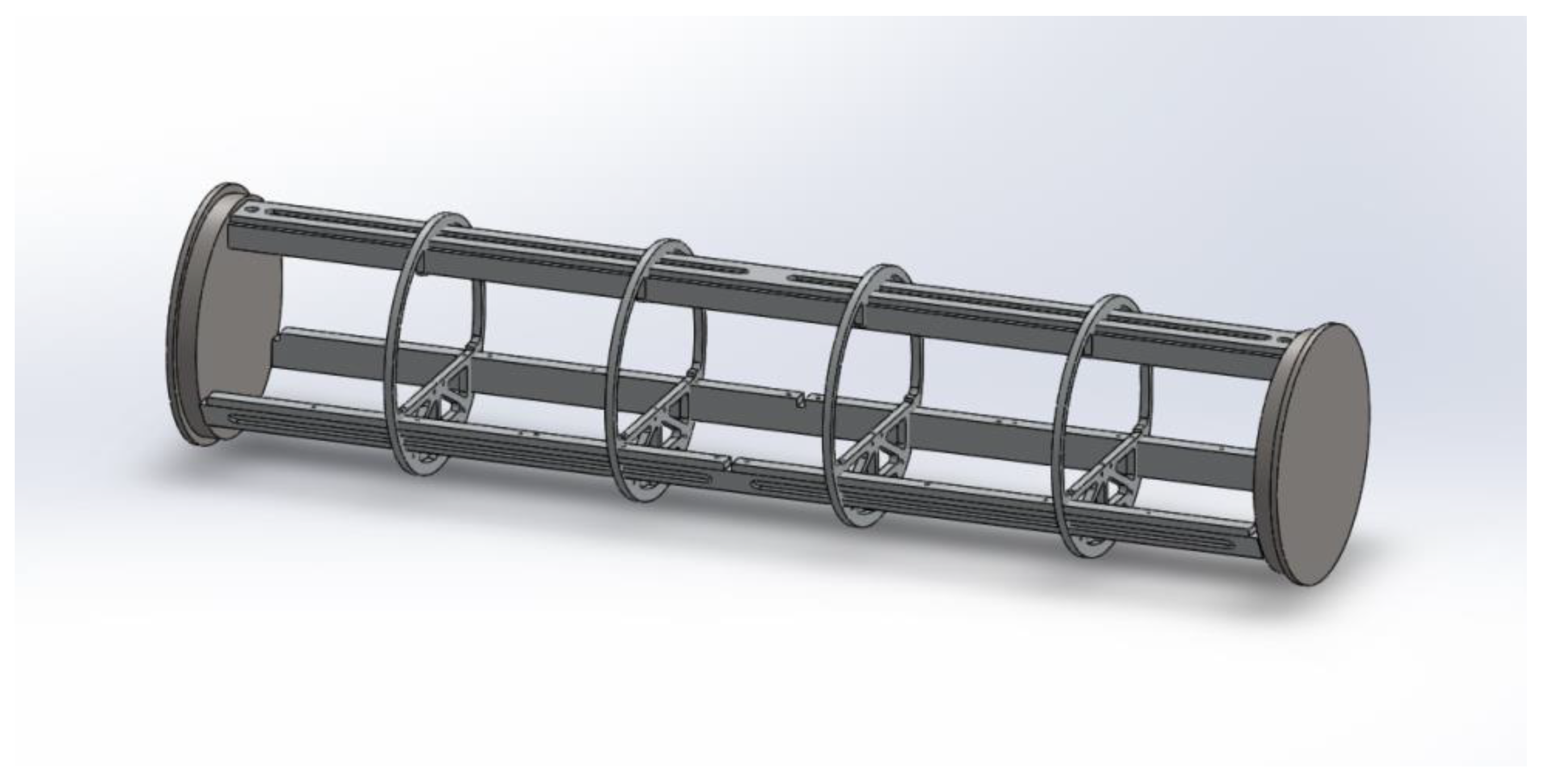
Figure 10 shows a schematic three-dimensional view of the internal structure of the AUV which serves as a support to accommodate the electronics inside the vehicle. It must be observed that the same number of ring stiffeners (4) is considered in this case, but now they are not fixed in the shell. In this section, the effectiveness of such movable internal structure is checked in terms of the increase in the critical buckling pressure, when compared to the buckling pressures obtained by the two previous shell designs.
The critical buckling pressures in this last case were once again obtained via linear buckling analyses using the same element types presented in the previous section (shell181 for the shell and solid187 for the four rings and other structural members of the inner platform). Contact elements (conta174) were also used to represent the contact between the shell and the outer surface of the ring stiffeners.
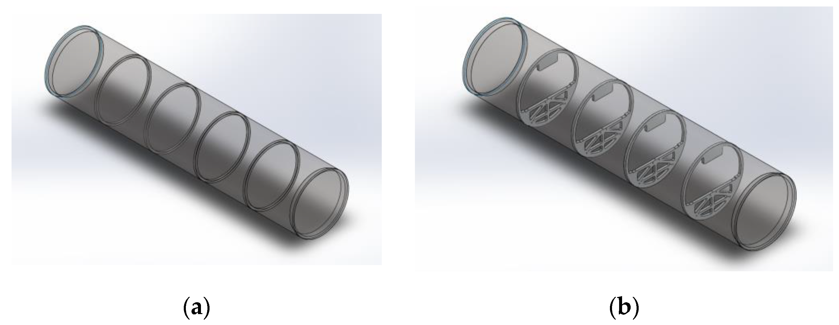
Figure 11 shows the basic geometries considered in the analyses of the conventional stiffened shell (as presented in
Section 3) and in the analyses of the shell with sliding stiffeners (as presented in this section) to highlight the differences.
It must be observed that, for this new shell design, gap formation between some parts of the shell and parts of the ring stiffeners does occur (after buckling) since the ring stiffeners are not fixed to the shell. A friction coefficient of
μ = 0.2 between shell and stiffeners was used in all the analyses of this section.
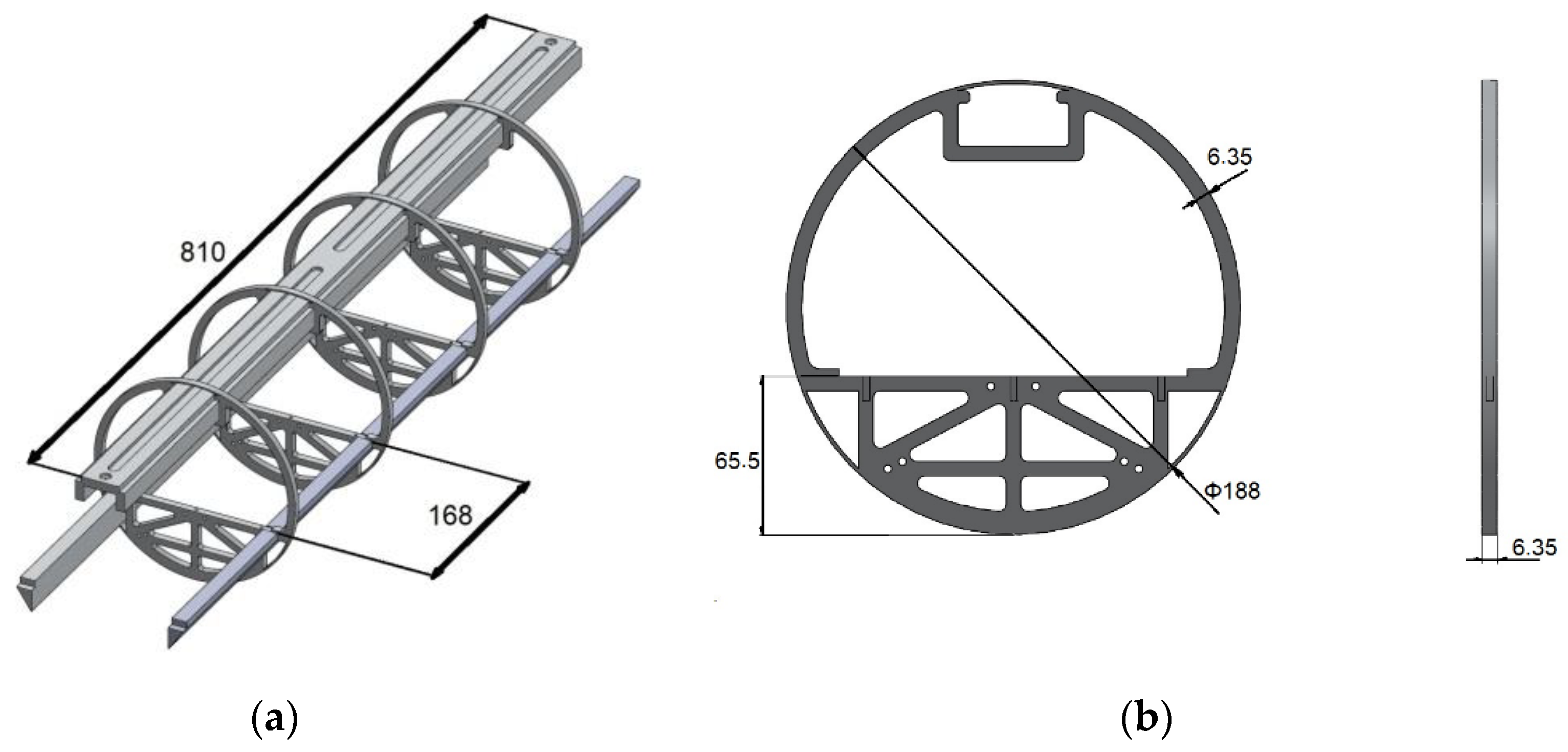
Figure 12 shows all the elements that were used to represent the sliding stiffeners in the finite element analysis (the longitudinal members were erased in
Figure 11 to make it clearer).
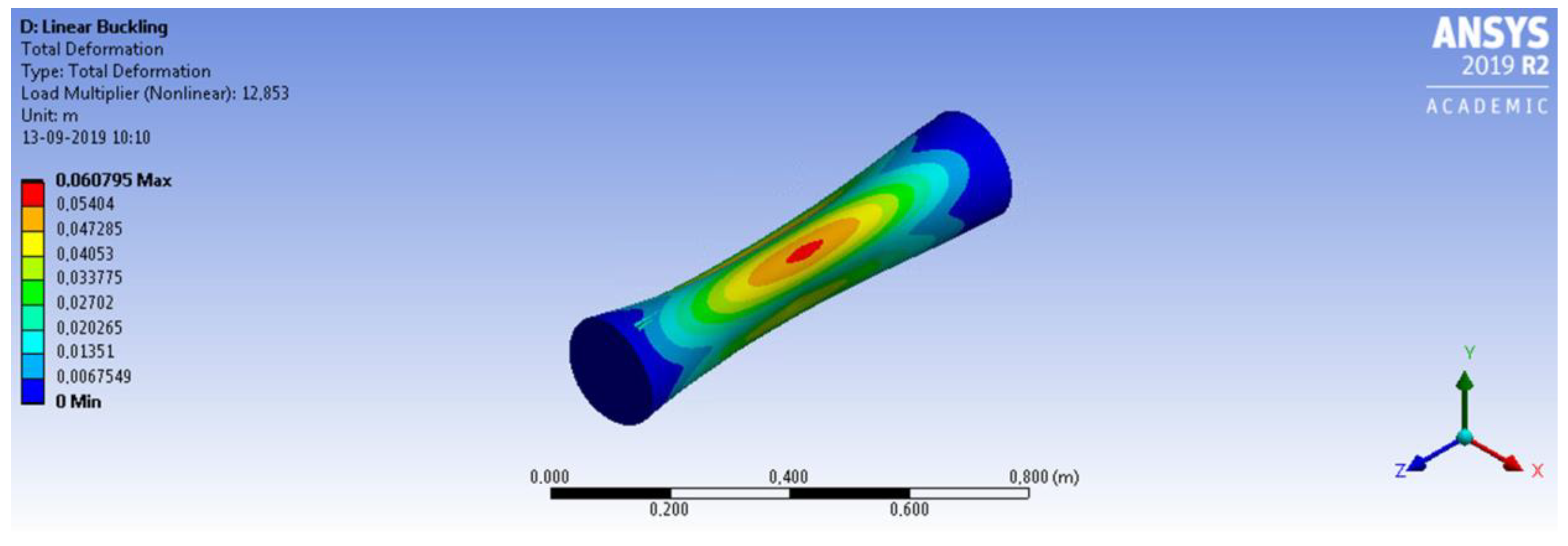
Figure 13 shows the convergence analysis obtained in this last case, where the least value for the critical buckling pressure was about 12.85 MPa, which represents a 41% increase in the critical buckling pressure, if compared to the FEM value achieved for the unstiffened shell, and a 14% increase in the critical buckling pressure if compared to the FEM value achieved for the conventional stiffened shell. Thus, the contribution provided by the sliding stiffeners shown in
Figure 12 indeed improved the buckling strength of the AUV. Although such elements have been initially conceived to serve as a simple support to the electronic devices boarded into the AUV, it was shown that they may also provide a good increment in the buckling strength of the vehicle.
Figure 14 shows the eigenmode and the corresponding eigenvalue (load multiplier = 12.85) obtained using a linear buckling analysis, showing that a generalized buckling mode is again obtained in this case.
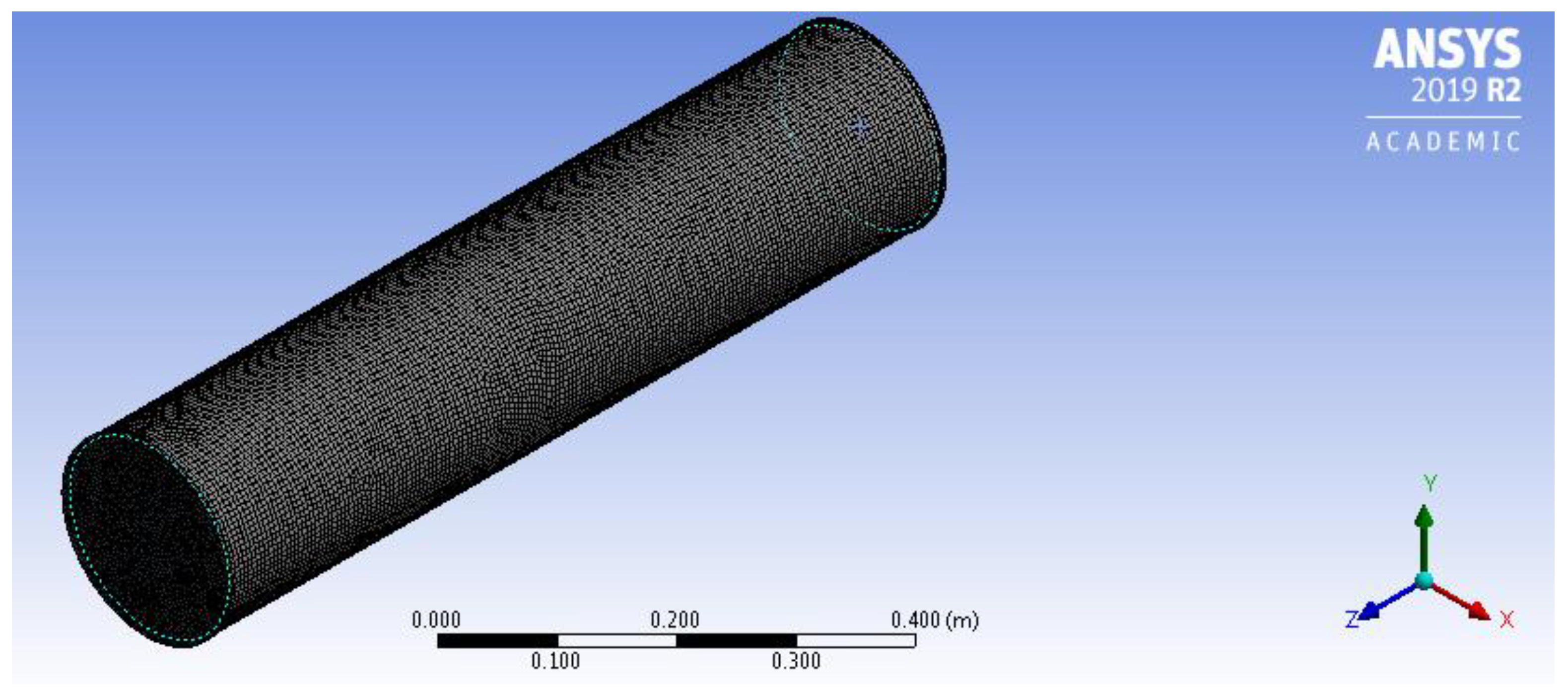
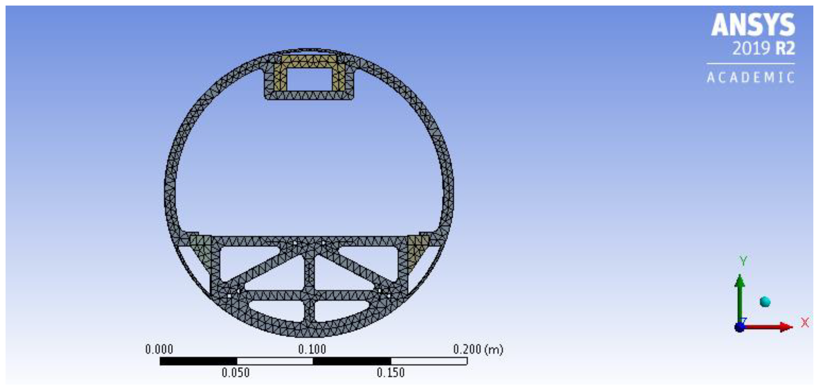
Figure 15 and
Figure 16 show the meshes used to obtain the lowest eigenvalue (12.85 MPa). In this last analysis, about 153,000 elements were used in the simulation.
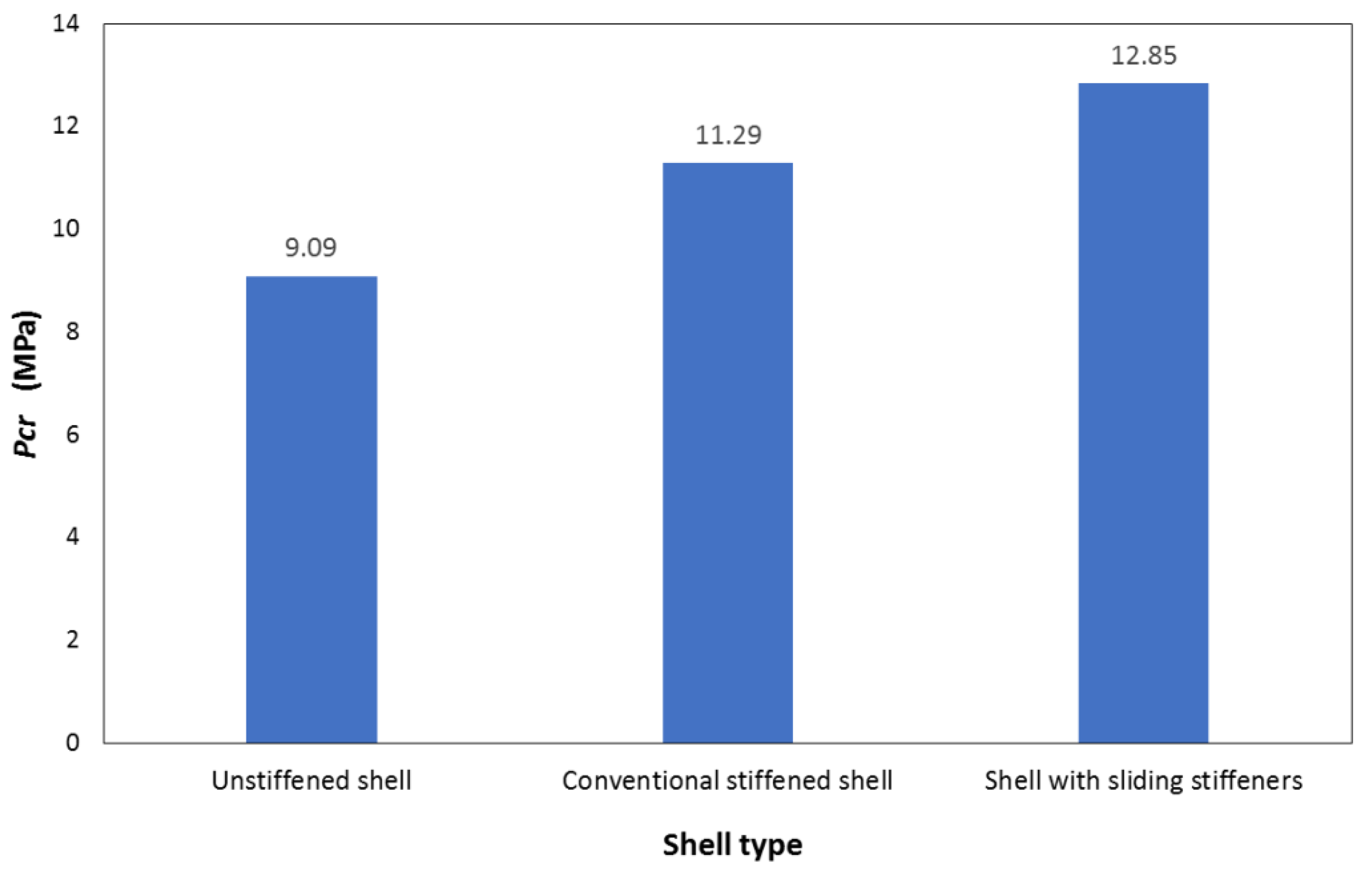
Figure 17 compares the finite element results obtained for the critical buckling pressures considering the three studied cases: (i) the unstiffened shell case (
Section 2), (ii) the conventional stiffened shell case (
Section 3), and (iii) the shell with sliding stiffeners case (
Section 4). It can be noticed that the solution provided by the sliding stiffeners added several advantages to the AUV design: ease of manufacture (since the ring stiffeners are not welded to the shell), reduction of the manufacturing cost (by the same token), and increase in the buckling strength of the structure, meaning a direct increase in the water depth at which the vehicle can operate.
Table 4 shows the three first eigenvalues obtained by the finite element models for each of the shell designs presented in this work. It must be stressed, however, that interactions among different buckling modes can exist in real (not “perfect”) structures. Such interactions are triggered by imperfections (even very small ones) which are always present in real structures, leading to a limit load that can be significantly lower than the smallest critical load of a perfect cylindrical shell (see, e.g., Liguori et al. [
18]). Thus, it is highly recommended to use nonlinear analyses to obtain safer results for the critical buckling load.
5. Geometrically Nonlinear Analysis of the Shell Considering Small Imperfections
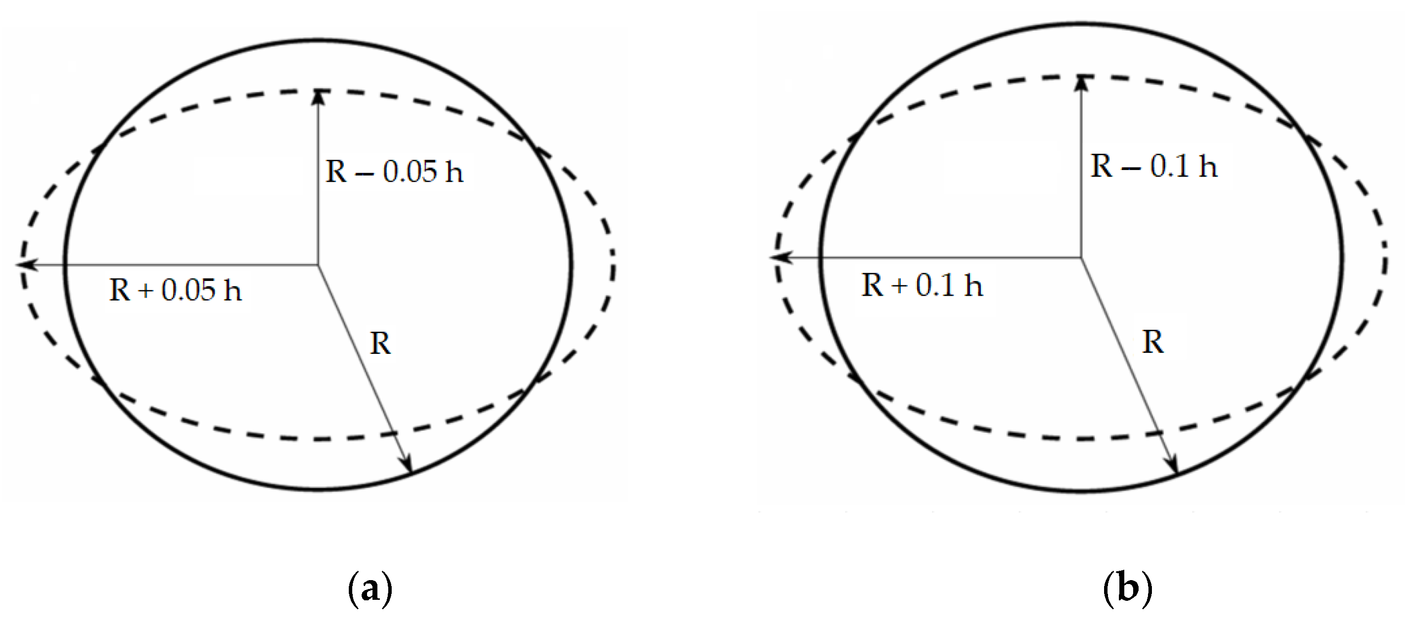
All results presented in the previous sections were obtained for a perfect cylindrical shell using a linear buckling formulation. In this section, the role of small imperfections in the critical pressure of the shell with sliding stiffeners will be considered, which was shown to be the best choice for the AUV design (among the three studied possibilities). The geometric imperfections, in the form of a shell ovalization, are imposed on the shell using the first mode of instability (of the perfectly cylindrical shell) to represent its initial shape. The maximum values for the imperfections are assumed to occur at the mid-section of the shell and are proportional to the shell thickness. Two different maximum values will be considered in the analyses: imperfections of 5% and 10% of the wall thickness, as represented in
Figure 18. It is important to stress that the choice of such an imperfection shape is an attempt to reproduce the initial geometry of the shell considering small deviations in the fabrication process (leading to an out-of-roundness) or even an accidental load that has permanently deformed the shell. Yet, as real structures may exhibit other different types of imperfection (e.g., thickness variations along the length or along the circumferential direction, dimples, indentations, etc.), it is necessary to investigate their sensitivity to different shapes and magnitudes of the considered imperfections (see, e.g., Wunderlich and Albertin [
21]). Thus, the analyses carried out in this section must be seen as examples and do not have the intention to cover all the possibilities.
The results obtained for the critical buckling pressures after running the geometrically nonlinear buckling analyses are shown in
Figure 19, which presents the critical buckling pressure obtained by the linear bifurcation analysis carried out in
Section 4 for the shell with sliding stiffeners, and the two nonlinear curves, obtained for the same structure, considering the two imperfection values. These curves show how the maximum radial deflection in the shell varies as the hydrostatic pressure increases. It is possible to notice that the buckling pressure decreases from 12.85 MPa to 11.16 MPa when an imperfection of 0.05
h (
mm) in the mean radius is considered, meaning a 13% reduction in the critical pressure. In the second case, for an imperfection of 0.10
h (
mm) in the mean radius, the nonlinear analysis shows that the critical buckling pressure decreases from 12.85 to 10.53 MPa, meaning an 18% reduction in the buckling pressure. Thus, although these imperfection values are relatively small if compared to the mean radius (about 0.3% and 0.6% of the mean radius, respectively), they reduce the buckling strength of the AUV in a large amount and, of course, they must be considered in the AUV structural design. This shows why safety factors of about 3 are still used in the AUV engineering practice.


 ,
, 


