
A Unified Numerical Method for Broaching and Loss of Stability in Astern Seas


1
China Ship Scientific Research Center, Wuxi 214082, China
2
Maritime Safety Research Centre, University of Strathclyde, Glasgow G4 0LZ, UK
*
Author to whom correspondence should be addressed.
J. Mar. Sci. Eng. 2023, 11(8), 1555; https://doi.org/10.3390/jmse11081555
Submission received: 3 July 2023
/
Revised: 26 July 2023
/
Accepted: 1 August 2023
/
Published: 6 August 2023
(This article belongs to the Special Issue Research on Seakeeping, Stability and Maneuvering in Waves of Marine Vessels and Floating Structures)
Abstract
:The interim guidelines of second-generation intact stability criteria and their explanatory note were issued by the IMO in 2022. However, due to their complexity, the direct stability assessments of broaching and loss of stability still need to be made easier for users. Therefore, the mathematical models for broaching and loss of stability in astern seas are studied in this paper. Firstly, a time-domain 6 DOF numerical model is adopted, combining seakeeping and maneuvering mathematical models. Secondly, the hydrodynamic forces, heave, and pitch motions are obtained by an enhanced strip method with the upright hull at different speeds in the frequency domain. Then, their time-domain values are transferred from their frequency-domain values with the speed variation considered. Thirdly, the time-domain varied wet hull in waves is captured by the 6 DOF ship motion. Then, the Froude–Krylov and the hydrostatic forces in the surging, swaying, rolling, and yawing directions are simulated considering the wave pressure around the wet hull. Fourthly, the exposure of the twin rudders and the wave-particle velocity are considered for predicting broaching. Finally, the calculated results are compared with the published results. The results show that the time-domain 6 DOF coupled numerical model can be unified for predicting broaching and loss of stability in the astern seas.
1. Introduction
After 20 years of efforts by worldwide researchers on stability in waves, an epoch-making achievement in the shipbuilding industry was realized; the interim guidelines of the second-generation intact stability criteria and their explanatory note were issued by the IMO in 2020 and 2022 [1,2]. Five stability failure models with multiple levels criteria, such as Level 1 and 2 criteria and Level 3 direct stability assessment, are included in the new stability criteria. For evaluating the new stability criteria, a software named HydroSTAB-CSSRC was developed by the stability group in CSSRC, including the numerical codes for predicting broaching and loss of stability developed by the first author. In addition, two documents on direct assessment methods of broaching [3] and loss of stability [4] were submitted to IMO by the Chinese Delegation. However, broaching and loss of stability are extreme nonlinear motions in waves related to the maneuvering sway and yaw forces, the body’s exact roll-restoring force, the zero-encounter frequency problem, the rudder force, and the rudder exposure in waves. Therefore, the numerical results in these documents could depend on selecting some crucial elements, and the introductions in these documents need to be more detailed. Predicting these motions in waves is still tricky at this stage. Hence, this paper gives detailed introductions and first unifies the mathematical model for the two extreme phenomena in waves.
During surf-riding, the boat is often unstable and turns uncontrollably despite keeping a maximum rudder angle in the opposite direction, defined as broaching. Broaching is a dangerous phenomenon in the astern seas for high-speed ships with ship lengths smaller than 200 m. The new stability criteria require at least a 4 DOF coupled motion of surge–sway–roll–yaw for numerical predicting broaching.
Establishing the numerical method of broaching has taken a long time for many researchers. Du Cane and Goodrich [5] reported that a sudden yaw could be controlled difficulty by steering in very steep waves of large amplitude, and the phenomenon is now named broaching. Prof. Umeda studied surf-riding in a regular wave and its probability in irregular waves in his Ph.D. thesis. Then, a 4 DOF coupled motion of surge–sway–roll–yaw for broaching prediction was investigated [6]. To provide an accurate numerical method for broaching prediction, the essential terms in the 4 DOF coupled motion were studied with fishing vessels [7]. The 4 DOF coupled motion of surge–sway–roll–yaw was also utilized for predicting broaching with the ONR ship, and a reasonable prediction for broaching was achieved [8].
Predicting broaching quantitatively using the ONR tumblehome with twin rudder and propellers by personal academic exchange with Prof. Hashimoto is still challenging. The twin rudder forces are a crucial factor in predicting broaching. The twin rudder normal forces are investigated by a free-running model experiment to improve a broaching numerical model [9]. Broaching is an extreme maneuvering phenomenon in astern waves with high speed, and the above 4 DOF coupled motion is derived from a Manoeuvring Modeling Group (MMG) model. There are so many expressions on the maneuvering mathematical model. Therefore, Yasukawa and Yoshimura introduced a standard maneuvering mathematical model [10]. A 4 DOF coupled motion of surge–sway–roll–yaw for numerical predicting broaching was refined using the ONR flare topside vessel [11]. The effect of the flare topside shape on the rolling angle during broaching was investigated [12]. The broaching probability of the tumblehome in irregular seas with the flare’s rudder parameters was given [12], and the experiment of broaching in irregular seas using the tumblehome with the flare’s rudder at the same wave condition was conducted in the seakeeping basin (170 m length, 40 m width, 6 m depth) of CSSRC in March 2023. The broaching prediction of irregular waves based on the method in this paper could be discussed at STABS2024, which will be held by CSSRC in 2024. The measured wave-induced forces and moments could be more significant than those in simulations [13].
It is also reported that surf-riding and broaching calculated by the code LAMP is used for evaluating probability with a split-time formulation, and its time-domain method of broaching is not published [14].
Loss of stability is another stability failure model in astern seas with high speeds, and it is also a phenomenon in the new stability criteria. Recent research also proves that time-domain significant roll motion during a loss of stability is affected by the maneuvering force in the astern seas [15].
The preliminary research by Paulling [16,17] and Allievie [18] increased our knowledge of stability in waves. Loss of stability is considered as the event where the ship loses static restoration at the wave crest in the early stage. As the research work has become further and more detailed, stability loss has been considered a significant roll motion due to the lost roll-restoring arm at the crest with a long time in following seas [19]. This phenomenon was further confirmed with a 4 DOF motion by the authors [20].
With further research, stability loss is considered not “pure” in astern seas, and the maneuvering forces from the sway and yaw motions could produce a significant rolling motion in astern seas [21,22]. Following that, a new 4 DOF coupled motion of surge–sway–roll–yaw was submitted by the Japan Delegation at IMO [23]. IMO requested at least a 4 DOF coupled motion for evaluating time-domain stability loss at this stage.
Furthermore, a 6 DOF coupled motion is further intended to be derived by combining the maneuvering and seakeeping mathematical model for the phenomenon of loss of stability, where the amplitude and phase of heave and pitch motion varies with speed. Time-domain heave and pitch are utilized to calculate the roll-restoring variation in waves, and the rudder force is an essential factor for significant rolling during a loss of stability [24,25].
It is also reported that the loss of stability numerical simulated by the code LAMP is used for evaluating the capsizing probability in random seas with a split-time method. However, its time-domain approach ignores the effect of the surge, sway, yaw, and rudder [26].
Both broaching and loss of stability are related to the maneuvering force, the rudder force, the seakeeping force, the roll-restoring force, the thrust force, and the resistance. This paper intends to establish a unified numerical method in which the body’s exact FK force and the hydrostatic force are based on an existing plan for parametric rolling prediction [27,28,29], and maneuvering motions, such as sway and yaw, are considered. In addition, the rudder exposure and the wave-particle velocity are considered for predicting broaching.
The improvement includes the following aspects: (1) the mean wet hull is considered for the FK force in the surge direction in previous research [25]. In contrast, the body’s exact FK force in the surge direction is considered. (2) The rudder exposure is considered by judging the distance between the top of the rudder and the wave surface, while it is not considered in previous research [25]. (3) The wave-particle velocity is considered, while it is not considered in previous research [25]. (4) The twin rudders and propellers are considered separately due to the time-domain rudder exposure and the wave-particle velocity. (5) The 6 DOF mathematical model presented in previous research [25] is first used for broaching and unifying one method for both broaching and loss of stability first.
2. Mathematical Model
2.1. Coordinate Systems
Three coordinate systems, including a space-fixed coordinate system , a body-fixed system , and a horizontal body coordinate system , are utilized in this paper, as shown in [25].
2.2. Mathematical Model
The ship has 6 DOF motions in waves, and many researchers gave out 6 DOF mathematical models. However, it is still difficult to establish a perfect mathematical model for nonlinear phenomena, such as surf-riding/broaching and pure loss of stability. The authors presented a 6 DOF mathematical model for pure loss of stability in [25]. The frame of the 6 DOF coupled motion used in this paper is the same as that in [25]. Equation (1) is the surge motion without the diffraction force. Equations (2) and (4) are the time-domain maneuvering sway and yaw motion in waves for course maintenance. Equation (3) is the time-domain seakeeping roll motion in waves instead of the traditional maneuvering roll motion, and few maneuvering coefficients are used in the roll equation. The encounter frequency during pure loss of stability is low, and the encounter frequency during surf-riding/broaching is near zero. The heave and pitch motion could be divergent due to the divergence of the hydrodynamic force at a low frequency. Therefore, the frequency-domain heave and pitch motion are pre-obtained with different speeds using Equations (5) and (6). The frequency-domain added mass, damping coefficients, and diffraction force are also pre-calculated with different constant speeds. The transfer method from the frequency domain to the time domain is used to obtain the heave, pitch motions, and diffraction forces with the ship’s relative position to waves considered. The instantaneous yawing angle and the sway velocity are considered using Equation (9).
Course keeping is an essential part of the 6 DOF coupled motion, and the control equation is shown in Equation (10).
The subscripts P, H, and R refer to the propeller, hull, and rudder.
2.3. Maneuvering Hull Forces in Calm Water
The maneuvering hull forces and can be referred to in [25].
2.4. The Thrust and the Resistance
Twin propellers are considered in this mathematical model. The formulas on the propeller thrust with twin propellers are shown as follows. The wave-particle velocity is requested for predicting broaching in the new stability criteria. are the formulas for wave-particle velocity, referring to the position of the port and the starboard propeller.
The hull resistance is shown in Equation (15).
2.5. The Steering Rudder Forces
The steering rudder forces in [10] are referenced with the heeling effect added.
Twin rudders are considered, and the formulas in [30] are referred to. and are expressed in Equations (16)–(19). S means starboard, and P means port.
The rudder exposure and the wave-particle velocity at the position of the port rudder and the starboard rudder are considered for broaching.
2.6. Forces Excited by the Wave
The wave-excited forces are the critical factor for simulating ship motions in waves. The FK force () and the diffraction force () are rewritten in the authors’ previous reference [25], referring to [31,32].
The radiation forces , and the restoring coefficients () in the mathematical model are given by the following formulas. The divergence at a low encounter frequency is checked by referring to STFM [33] and OSM (Ordinary Strip Method) strip theory. Some formulas of radiation forces in the STFM are the same as those in the OSM, and some of those of radiation forces are not the same. OSM, STFM means the formulas of radiation forces are identical in the STFM and OSM. The OSM formulas of A22 and A66 are used because the STFM formulas of A22 and A66 are divergent with a low encounter frequency. Equation (39) is used for A46 and B46 to avoid divergence with a low encounter frequency. The radiation forces are divergent with a close zero-encounter frequency, but an interpolation method is used for the radiation forces with a near zero-encounter frequency avoiding calculating these values with a relative zero-encounter frequency.
2.7. Roll-Restoring Arm and Roll Damping
3. Experiments
The ONR tumblehome vessel is a standard model for developing the new stability criteria. A 1/40.526 scaled model was made, and the free-running experiments were conducted in the seakeeping basin of CSSRC.
The principal particulars and the system parameters are shown in Table 1 and Table 2, respectively. The maneuvering coefficients refer to [34].
Note: BR is broaching, and PL is pure loss of stability in Table 1.
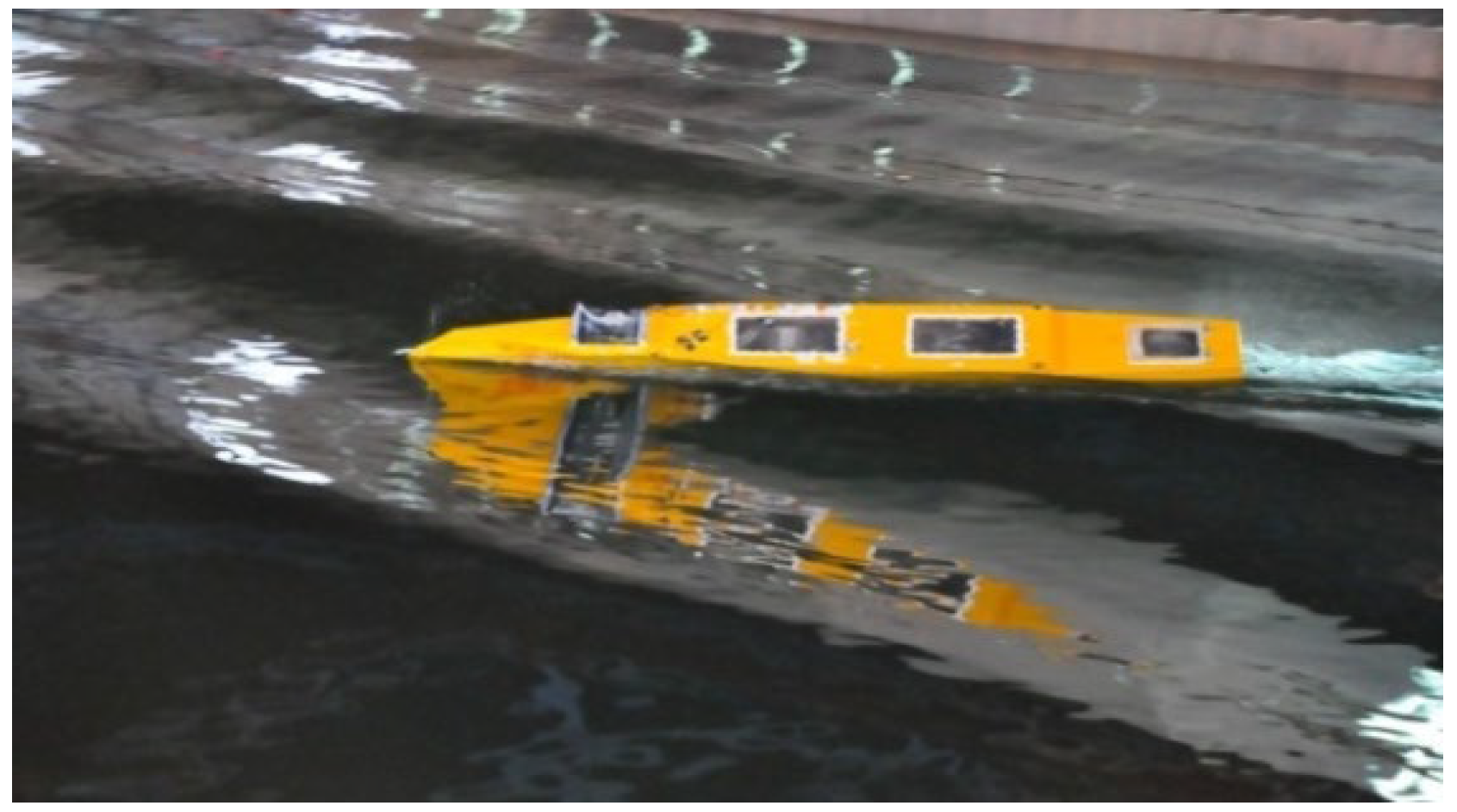
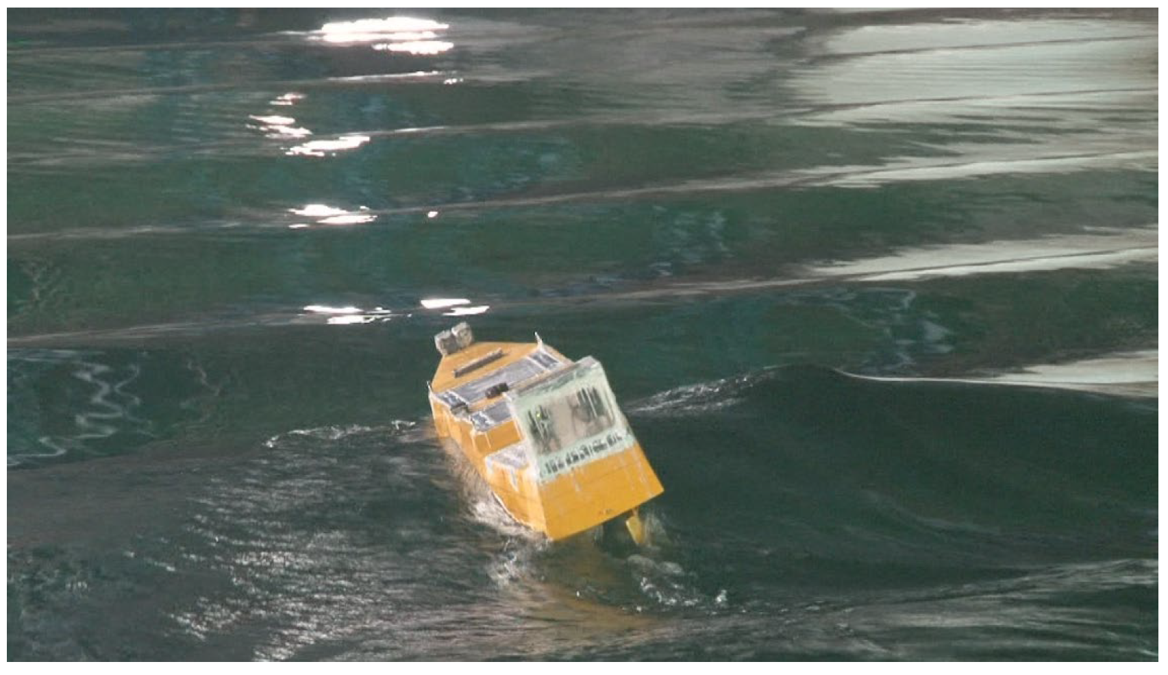
The snaps of broaching and loss of stability in the free-running experiment are shown in Figure 1 and Figure 2, respectively. The procedures for the experiments are included in the authors’ previous works [24,25].
The speed is a crucial factor for surf-riding/broaching and loss of stability. First, a total station system is used to measure the nominal speed in calm water with a specified propeller rate. Second, the nominal speed in calm water is used for the experiment in waves by using the same specified propeller rate. The forced free running due to reduced frictional resistance of ships in the ship propulsion points is not considered in the model test. Therefore, forced free running is not considered in the simulations.
The autopilots play a key role in the test. First, the model is kept with an initial heading. Next, a propulsion system is used for thrusting the ship with a specified propeller revolution, and then the ship model is released free in the waves. After that, the model is free-running with the autopilot course by a PD control system. The PD control system includes the optical fiber gyroscope equipped on the ship model, a steering gear, and a proportional autopilot for course-keeping that was simulated by the bias between the autopilot course and the instantaneous heading angle measured by the gyroscope and the yaw velocity measured by the gyroscope.
4. Simulations and Discussions
4.1. Validation of the MMG in Calm Water
The 6 DOF coupled motion is based on the framework of MMG, and the maneuvering coefficients and the rudder parameters are significant for predicting broaching. For testing the 6 DOF coupled motion in calm water, the following mathematical model is used for the roll motion.
The maneuvering coefficients of the ONR tumblehome were obtained from model tests by Umeda [35]. The maneuvering coefficients and the rudder coefficients were used in one system-based model by Araki et al. [34]. However, the maneuvering coefficients and the rudder coefficients used by Araki et al. [34] with a standard MMG model could not produce a good agreement of turning circles in calm water with both a rudder angle of 25 degrees and 35 degrees.
Some sensitivity rudder coefficients are adjusted, as shown in this paper, such as . The value is −0.157 and 0.0879 for the flare and tumblehome vessel in [9], respectively. The value is usually about 0.3, according to the empirical evidence. The value of −0.157 is used here.
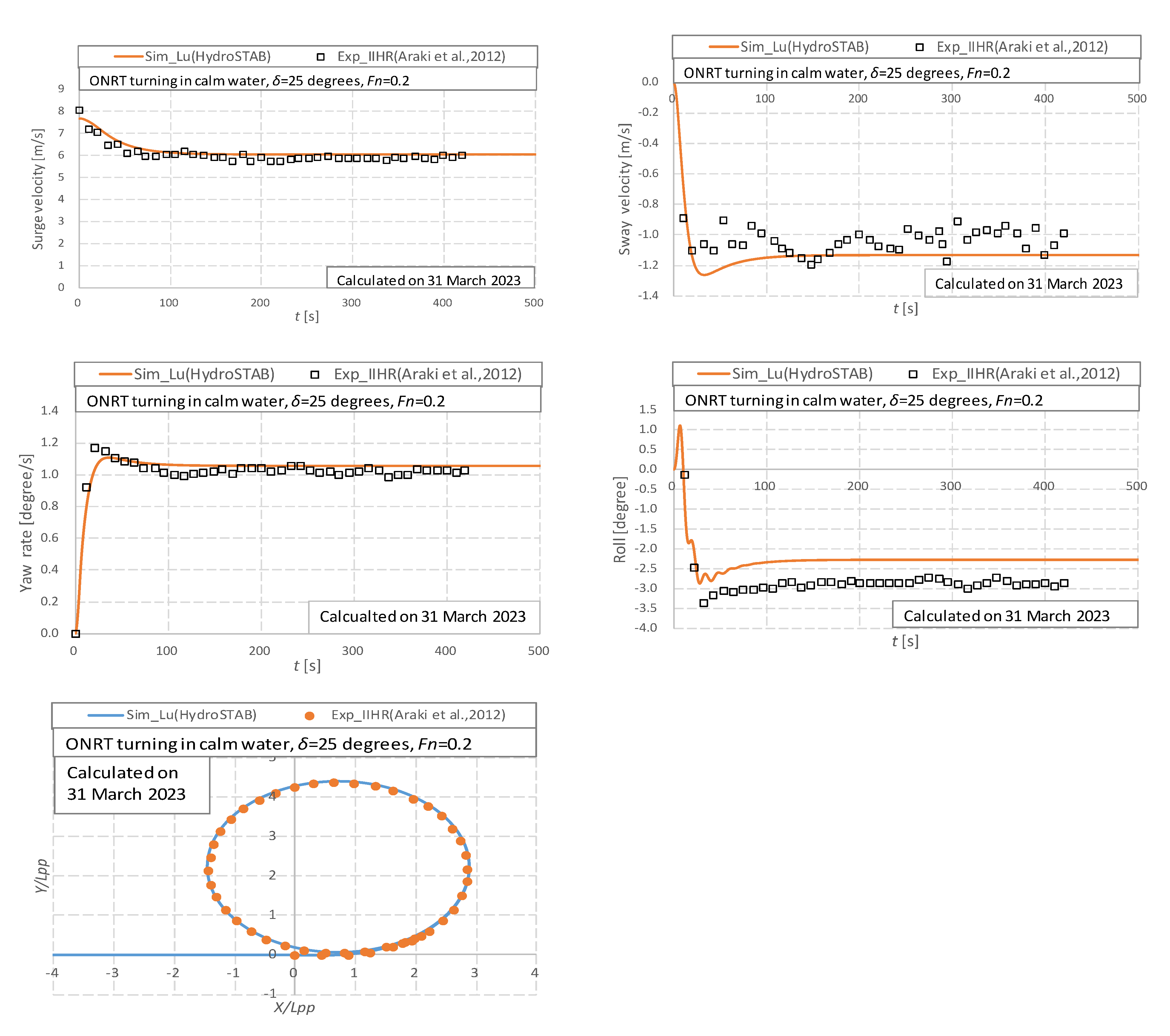
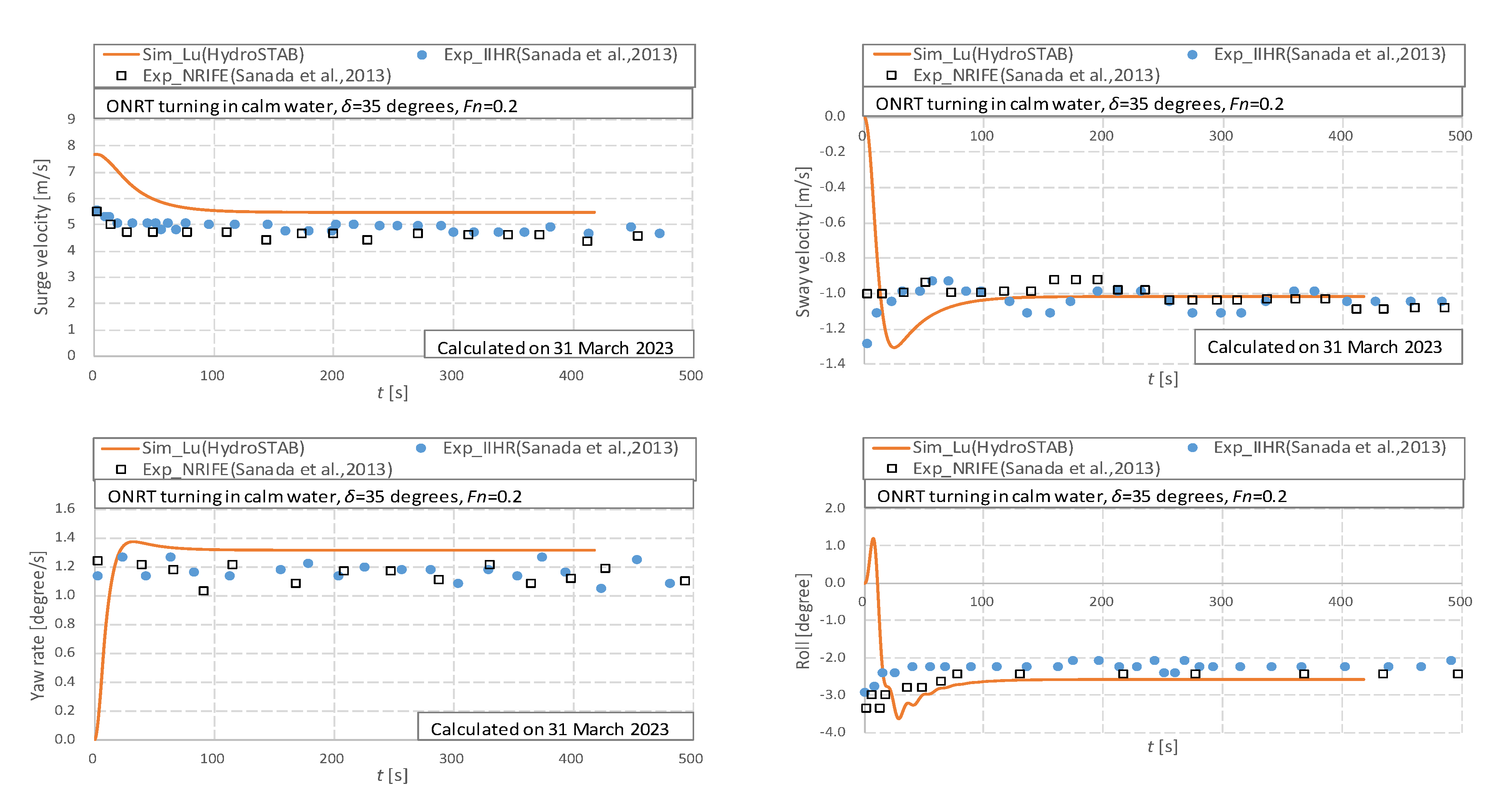
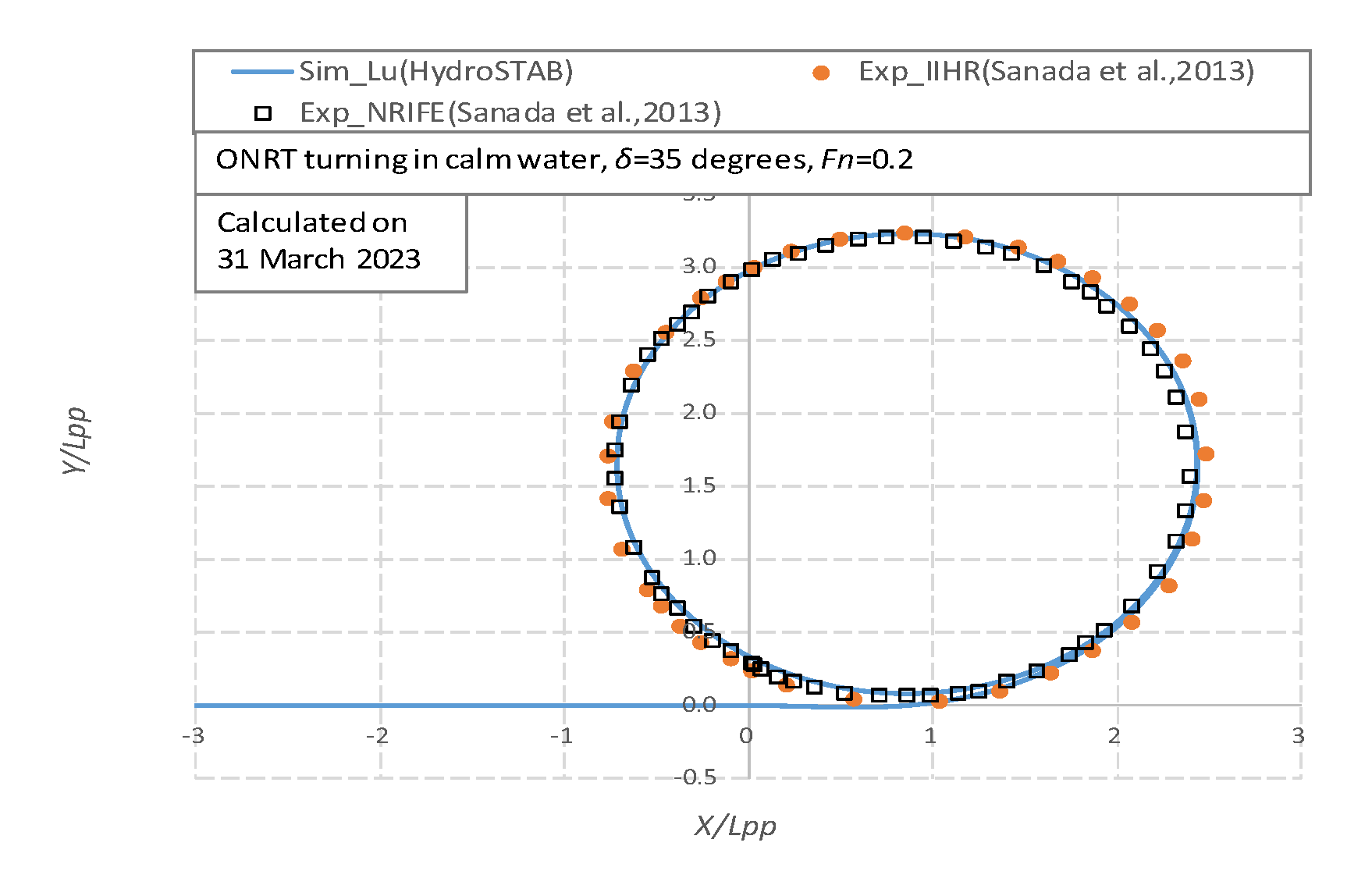
Before predicting broaching, the effectiveness of the mathematical model in calm water should be checked. By comparing the experimental results from [34,36], the maneuvering coefficients [36] and the rudder coefficients in this mathematical model for broaching, which are illustrated in Table 2, can produce agreement results of surge velocity, sway velocity, yaw rate, heeling angle, and trajectories of the turning circle for a rudder angle of 25 degrees and 35 degrees, respectively, as shown in Figure 3 and Figure 4. That means the rudder with the value of −0.157 and other coefficients used in this paper can produce a balancing force with the maneuvering force of the ship.
4.2. Validation of the Seakeeping Motions
The transfer method from the frequency domain to time domain is utilized to obtain the heave and pitch motion with the simultaneous relative position of the ship to wave. And then, parametric roll can be predicted, which is recommended by Prof. Umeda. Following this method, the frequency-domain heave and pitch motions are pre-calculated with different constant speeds by an enhanced strip method for predicting loss of stability by Jiang Lu et al. [24,25].
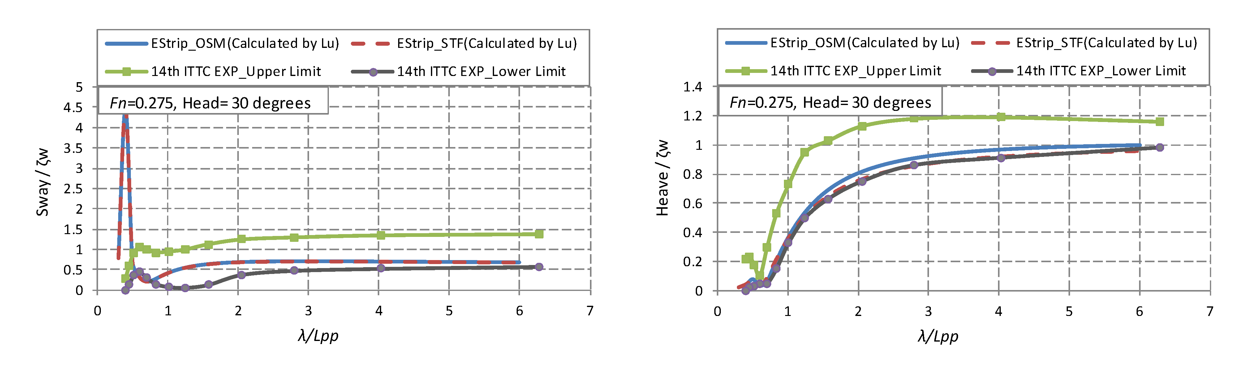
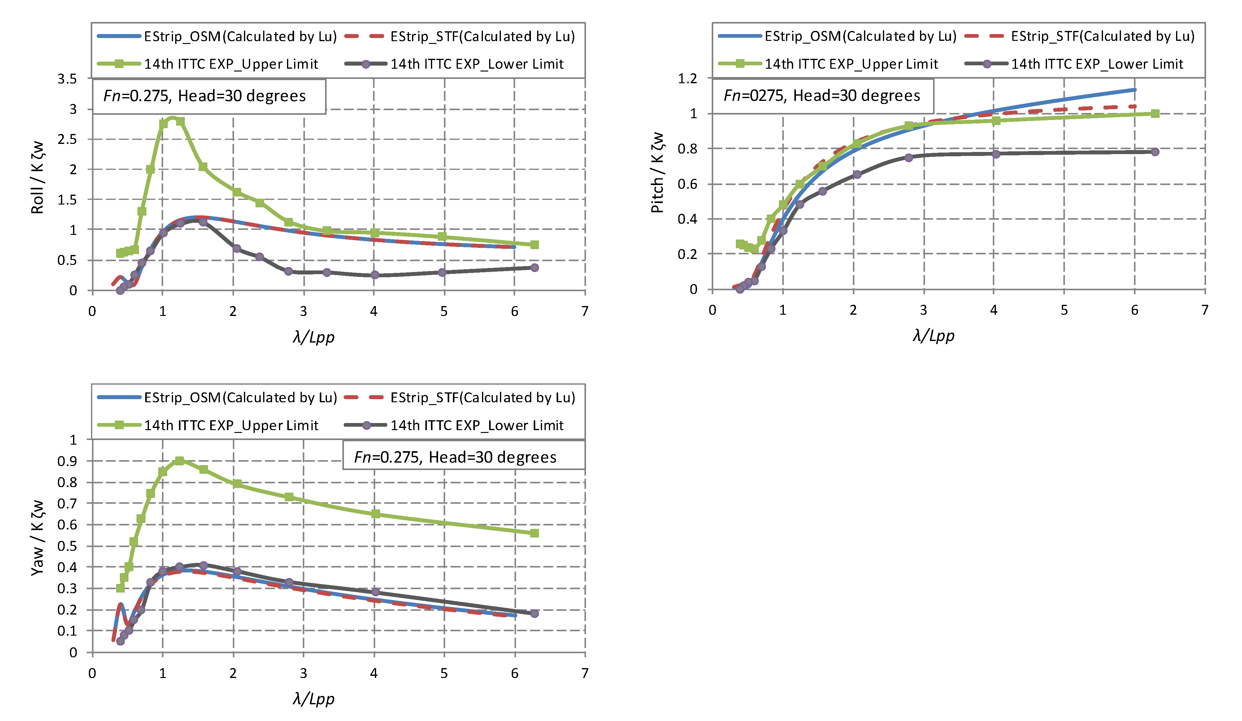
Broaching and loss of stability are stability failure modes of high-speed ships in waves. The seakeeping motions are the base for these phenomena. For validating the seakeeping motions, the sway, heave, roll, pitch, and yaw motions are calculated by OSM and STF strip methods, where the velocity potential is solved by an enhanced integrating way, and are named EStrip_OSM, EStrip_STF in this paper. The calculated seakeeping results are compared with the experimental error band published by the 14th ITTC. Both EStrip_OSM and EStrip_STF can produce good results in stern quartering waves with Fn = 0.275, as shown in Figure 5. The frequency-domain amplitude and phase of heave and pitch motions are calculated by the EStrip_STF method at several constant speeds, while an interpolation method is used to consider the time-varied forward speed in this paper. The yaw amplitude by potential theory is generally smaller than that by tests, as shown in Figure 5. The reference [13] reported that the measured wave-induced yaw moments could be more significant than those in simulations. The wave-induced yaw moments are crucial for predicting broaching, and the theory of calculating wave-induced yaw moments should be further studied.
The RAO of the sway motion calculated in the frequency domain shall diverge at the zero-encounter frequency, as shown in Figure 5. It is due to the absence of restoring term in the sway direction in the frequency domain. The time-domain maneuvering mathematical model of the sway motion overcomes the frequency domain divergence.
4.3. Validation of Surf-Riding/Broaching
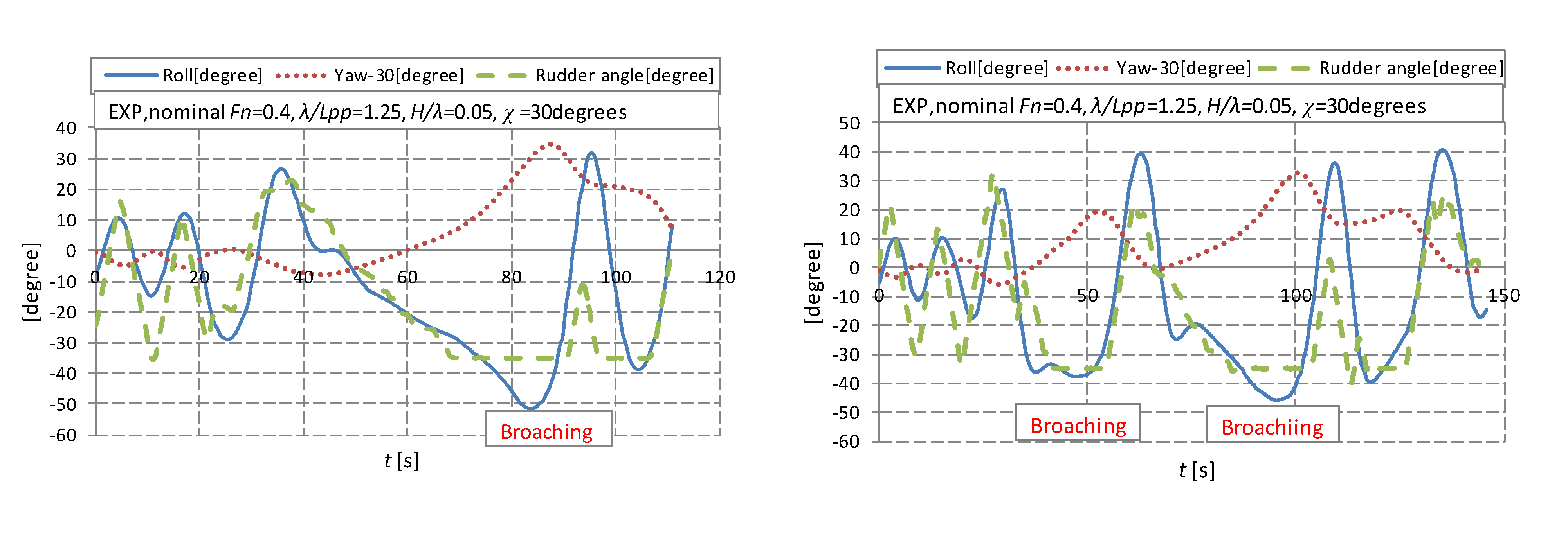
The wave of H/λ = 0.05, λ/Lpp = 1.25, χ = 30 degrees is used in this paper; the following sentences and figures do not mention the wave condition each time.
Umeda carried out experiments with the tumblehome hull in astern waves [35] to examine their mathematical model for surf-riding/broaching, and some experimental results were submitted to IMO by Umeda for developing the criteria of surf-riding/broaching. The free-running experiments with the ONR tumblehome vessel were conducted in regular following and stern-quartering waves at the seakeeping basin of CSSRC, and four types of motions, such as periodic motion, stable surf-riding, broaching without capsizing, and broaching with capsizing, were recorded [37]. The time-domain motions during broaching in the experiment are shown in Figure 6. Although the basin is only 69 m in length, two times of broaching in one wave case was recorded in the free-running experiment. Broaching in regular waves could lead to unstable roll motions and uncertainty in the maximum roll or capsizing in the experiments. Broaching is more complex than we know, and this topic can be discussed in future research.
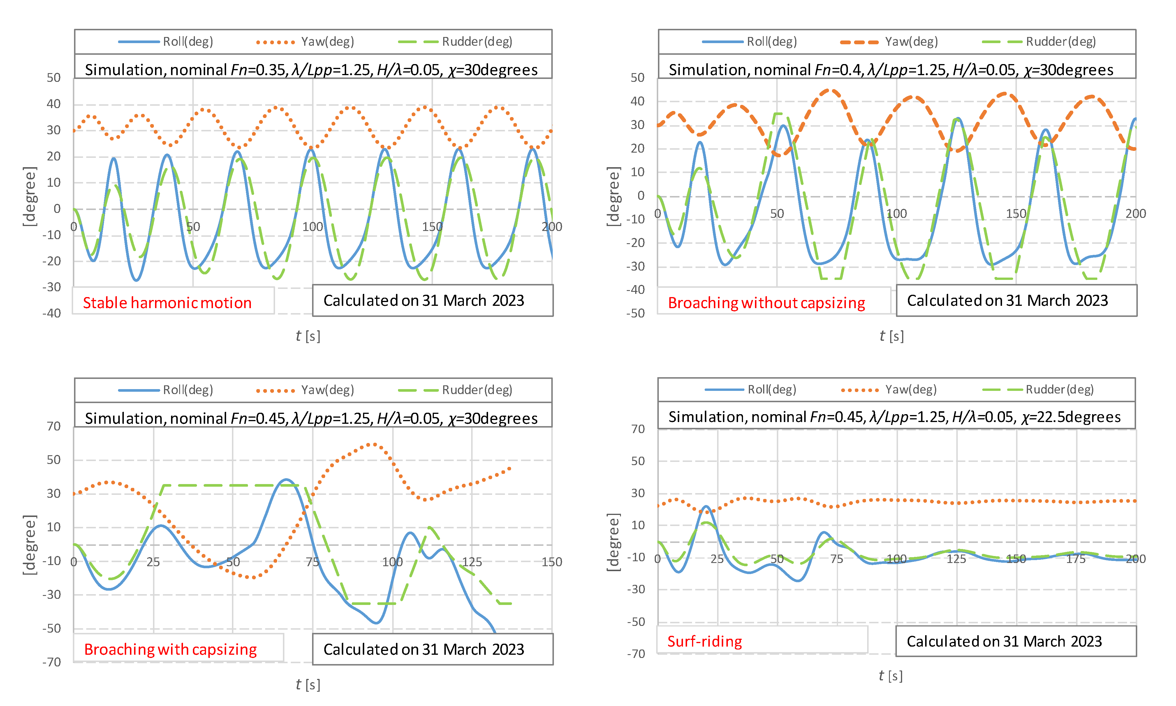
Time-domain numerical results of ship motion modes are shown in Figure 7. The four types of motions can be produced by the numerical simulations.
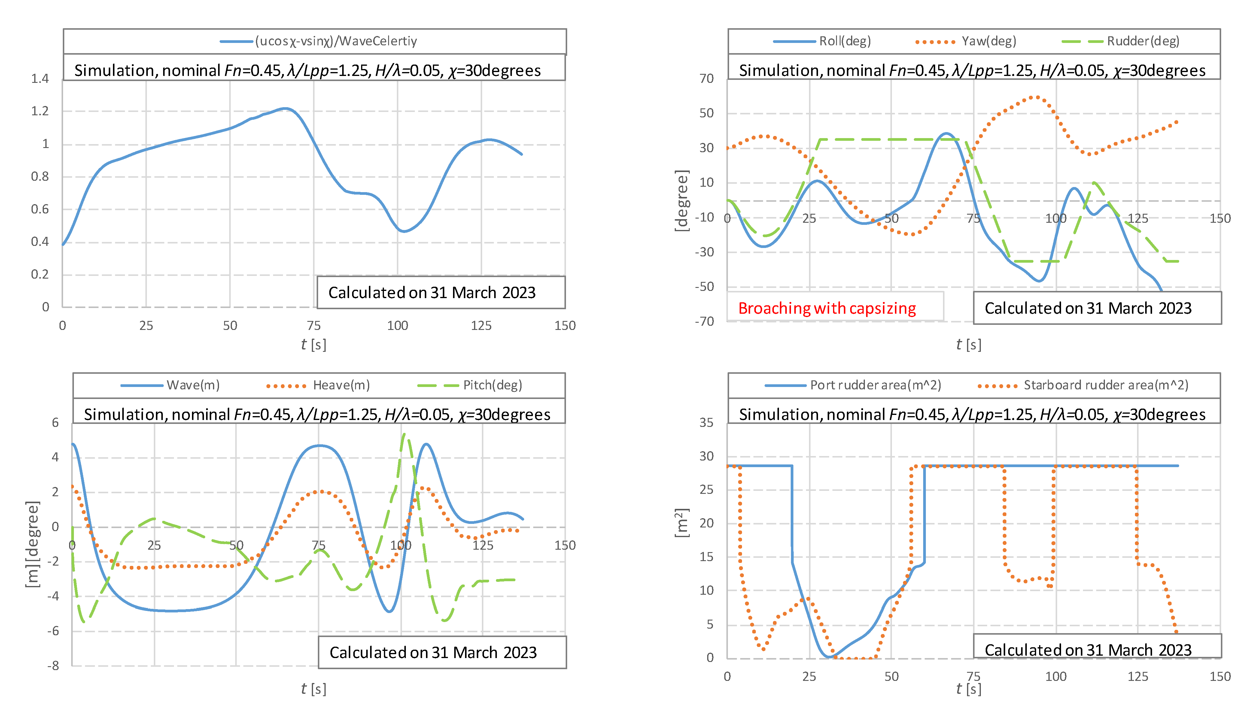
Time-domain numerical results of broaching with Fn = 0.45 are shown in Figure 8. The rudder exposure is significant during broaching, and the instantaneous rudder exposure is affected by the instantaneous wave profile, heave, pitch, and roll motions.
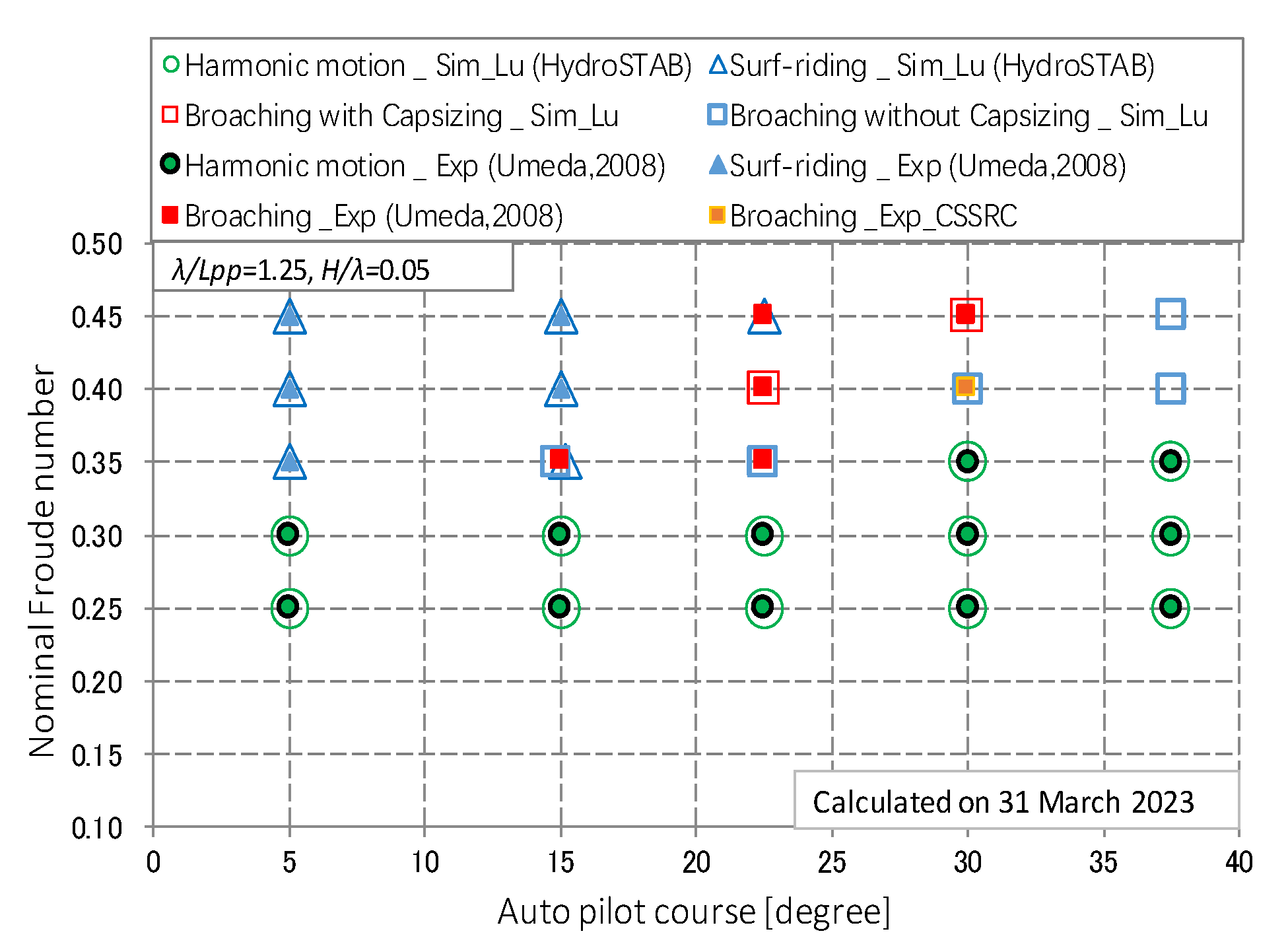
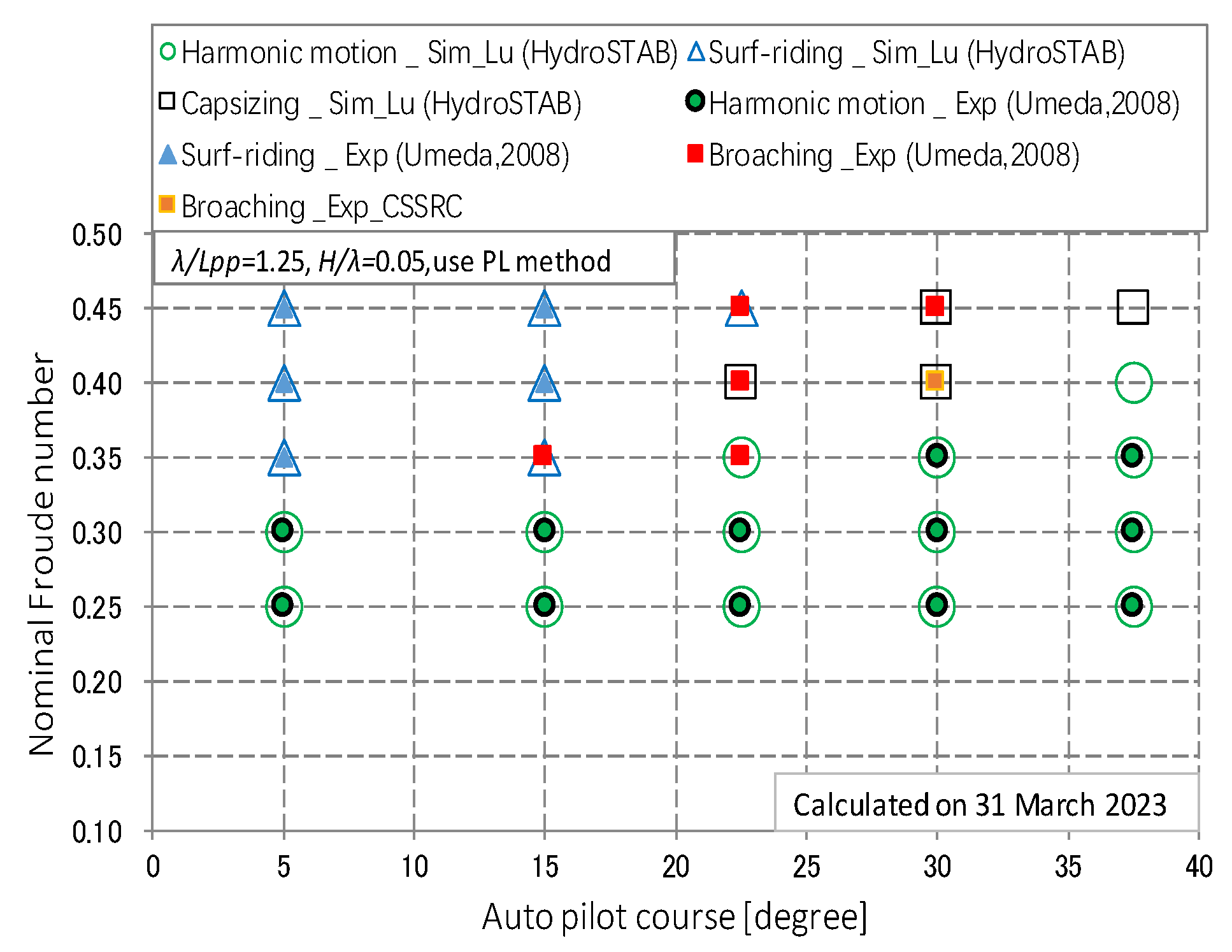
The 6 DOF coupled motion for loss of stability in astern seas [25] is further developed with the rudder exposure and the wave-particle velocity considered for broaching. The ship motion modes calculated by the 6 DOF coupled motion with different autopilot courses and nominal Froude numbers were compared with the published data [35,37]. A reasonable agreement can be achieved except for the case with autopilot courses 22.5 degrees and Froude numbers 0.45, as shown in Figure 9. The exposure of the starboard rudder is significant during enormous rolling to port, as shown in Figure 8.
The Froude–Krylov component FK1 in the surge motion is defined in Equation (12) of [25]. The sectional area S(x) can be calculated with the draft in calm water, named the mean wet hull. The sectional area S(x) can be calculated with the time-varied draft in waves, called the instantaneous wet hull.
The wave excited surge forces FK1 with the instantaneous wet hull and the mean wet hull are significantly different [38]. The wave-excited surge force could affect the surge motion and the relative state of the ship to the wave. Therefore, the ship motion modes by the 6 DOF coupled motion with the mean wet hull for wave excited surge force were compared with the published data [35,37], as illustrated in Figure 10. The difference between Figure 9 and Figure 10 exists only in the case of Fn = 0.4 and the autopilot course of 22.5 degrees, and the state reaches surf-riding in Figure 10. Surf-riding/broaching is sensitive to the ship's speed at the critical condition. The frequency-domain amplitude and phase of FK1 with the mean wet hull and the exact body are different. Therefore, the time-domain surge force is changed. Following that, the time-varied speed is changed. As a result, the time-domain relative position of the ship to the wave is changed. The time-varied yaw moment and rudder angle could also be changed. Surf-riding is considered the pre-condition of broaching, and surf-riding is also an unstable state. Therefore, a minor disturbance during surf riding could change the unstable state to broaching.
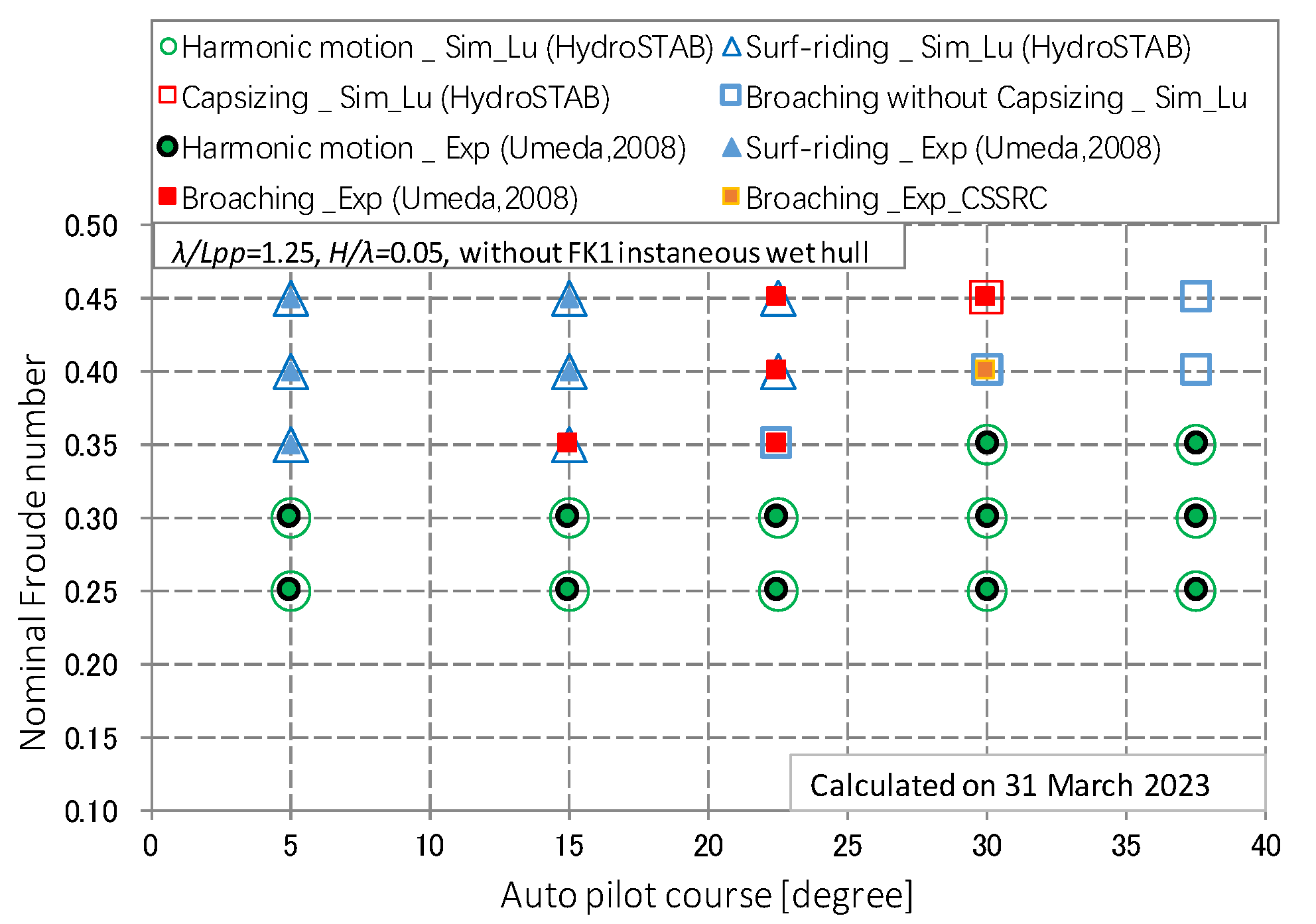
Based on the 6 DOF coupled motion for loss of stability [25], the rudder exposure, the wave-particle velocity, and the body’s exact wave excited surge force are further considered for unifying the mathematical model for broaching and loss of stability. The ship motion modes with periodic motion and surf-riding can be numerically calculated. Still, some cases of broaching cannot be evaluated accurately, as shown in Figure 11. The rudder exposure is significant in severe waves. The rudder forces in the yawing direction become tiny when the rudder exposure is substantial. Therefore, the rudder force is a crucial term for predicting broaching.
4.4. Validation of Loss of Stability
Loss of stability is also an extreme nonlinear phenomenon of high-speed ships in astern waves, and it is also a phenomenon in the new stability criteria. A static balance method is used to calculate roll-restoring variation, and then 2 DOF surge-roll coupled motion and 4 DOF surge–sway–roll–yaw coupled motion are used to evaluate the loss of stability [19,21,22,23]. The time-domain roll-restoring arm is calculated with the heave, and pitch motions are discussed in [20,24,25].
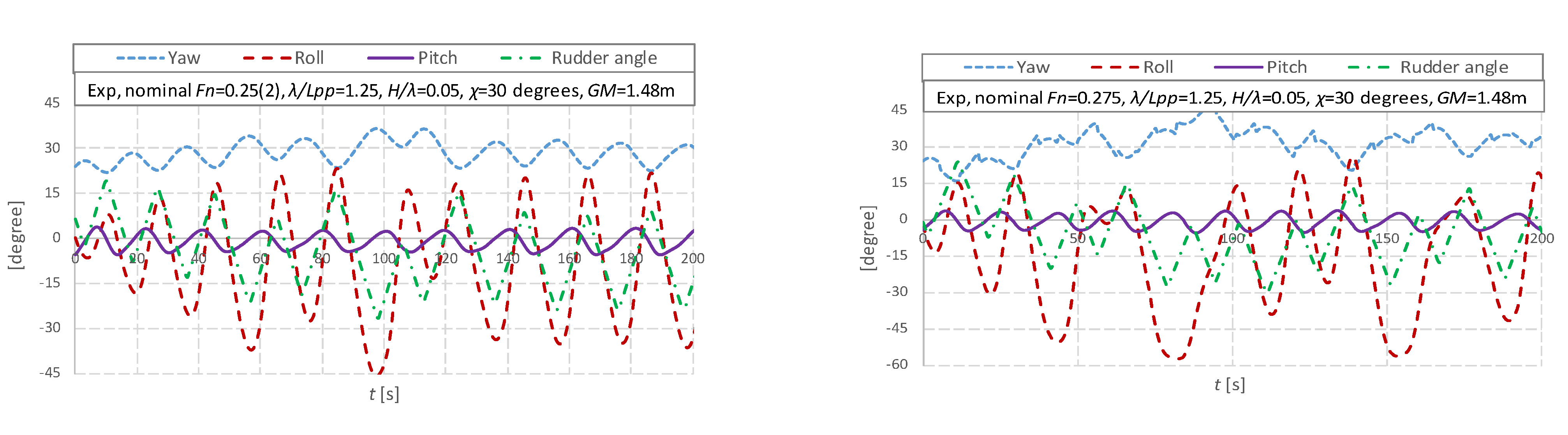
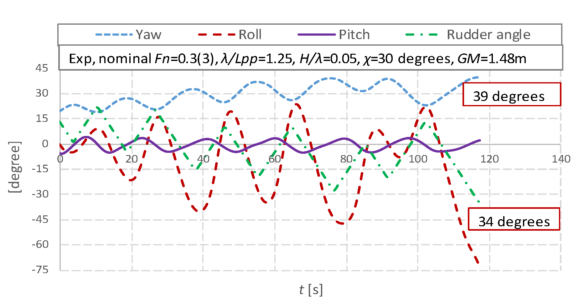
The time-history data of the rolling, pitching, and yawing motions are recorded with the rudder angle in the tests, as illustrated in Figure 12. An unstable rolling motion, subharmonic rolling with two times the encounter period, and capsizes due to yaw–roll coupling during the loss of stability are recorded in the experimental data, as illustrated in Figure 12, which are discussed by the authors in [25].
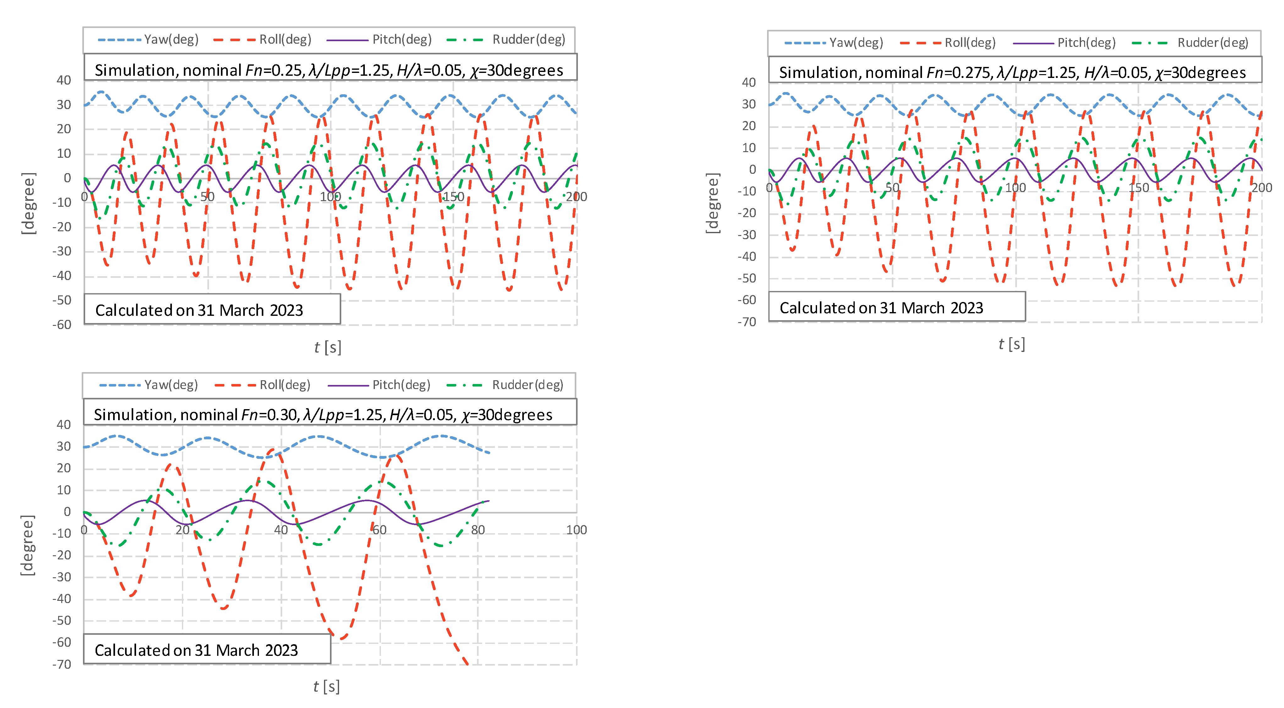
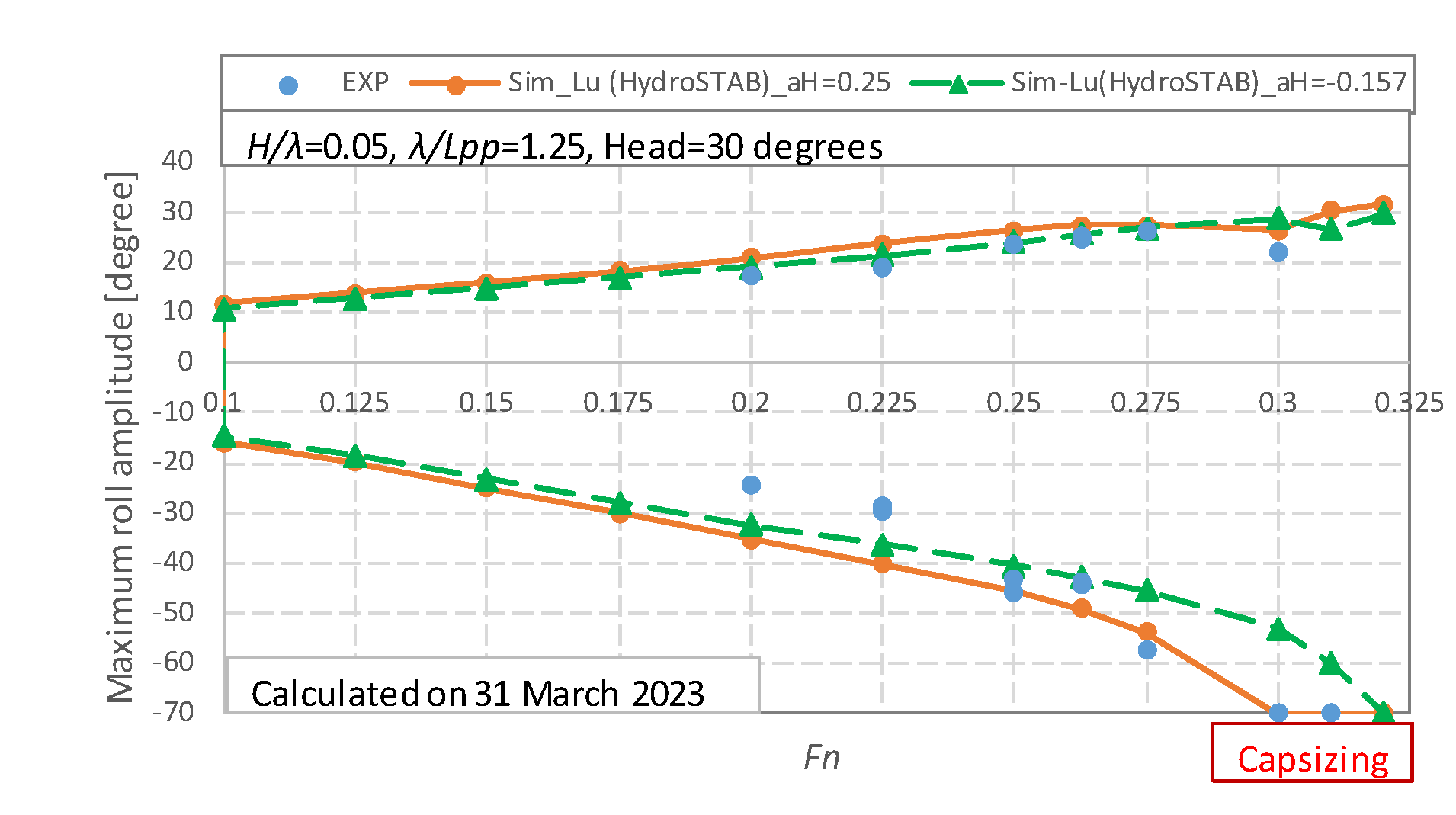
A 6 DOF coupled motion is established in the authors’ previous reference [25], and the parameters in Table 1 and Table 2 are used for evaluating loss of stability. The 6 DOF numerical results are shown in Figure 13. The maximum rolling angles during the loss of stability can be expected by the 6 DOF coupled motion, as shown in Figure 14. The numerical simulations with = 0.25, −157 are carried out, and the numerical results with = −157 underestimate the maximum rolling angle at the critical speed. The reason for this is that the rudder forces in the rolling direction are crucial for the significant roll during the loss of stability [25]. There is a considerable yaw angle during the loss of stability in astern waves. Therefore, to keep the course, the rudder angle is significant [25]. When GM is small, becomes large from the gravity of the ship, and then also becomes substantial. If = −157, the steering rudder force , as illustrated in Equation (19), is reduced, and then the roll angle becomes smaller than that with = 0.25.
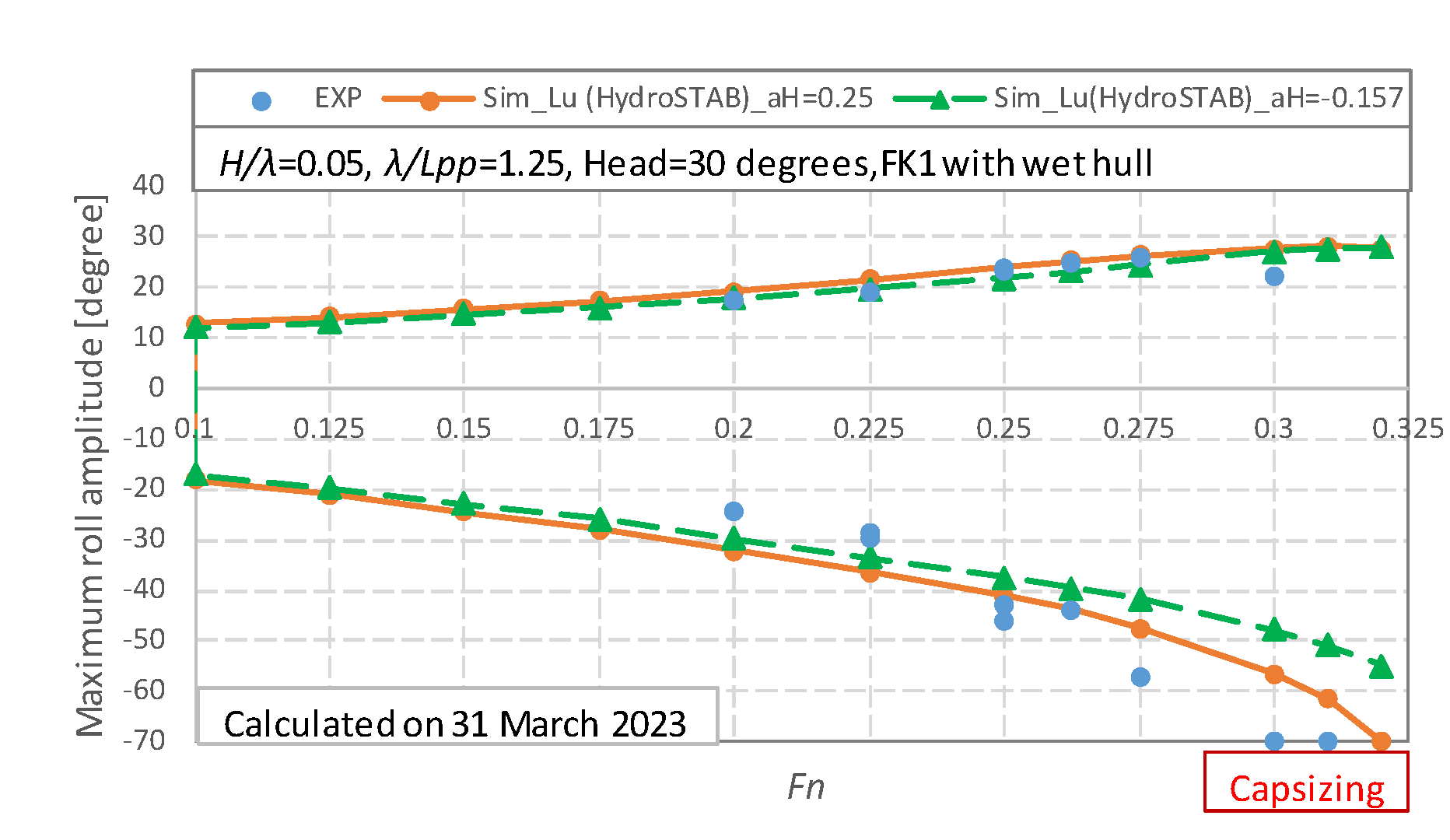
The wave excited surge force with the instantaneous wet hull is further considered, and the numerical results with = 0.25, −157 could underestimate the maximum roll angle, as expressed in Figure 15. The reason for this is that the surging force is a crucial reason for the significant roll during stability loss. Loss of stability is sensitive to the ship's speed. The amplitude and the phase of FK1 with the mean wet hull and the exact body are different, and the time-domain surge force and the instantaneous ship speed are changed. The state at the crest could be changed. Then, the roll angle could be affected during stability loss.
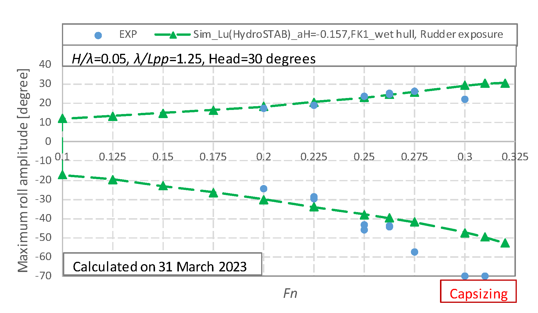
For unifying the mathematical model for broaching and loss of stability, the mathematical model considering the rudder exposure, the wave-particle velocity, and wave excited surge force with the instantaneous wet hull is adopted to predict the capsizing behaviors during a loss of stability, and the maximum roll angles are smaller than the experimental data, as illustrated in Figure 16. The reason for this is that the rudder forces are a crucial reason for the significant roll during stability loss [25]. Therefore, when the rudder exposure is considered, the rudder force is reduced, and the calculated maximum roll angle could become small.
The large rolling can be predicted by the 6 DOF coupled motion for loss of stability. The mathematical model with rudder exposure and instantaneous wetted surface for surge force seems perfect. However, the results of the maximum roll angles during stability loss are not better than that without rudder exposure and instantaneous wetted surface for surge force. The phenomena of the unstable rolling motion, and subharmonic rolling with two times the encounter period, are more complicated than our cognition at this stage, and these phenomena should be studied in the future.
5. Conclusions
A unified mathematical model for surf-riding, broaching, and loss of stability in astern seas is extended and established with the twin rudders ONR tumblehome vessel, and several conclusions can be obtained at this stage:
- Both rudder and surging forces are very important for broaching and loss of stability.
- The rudder exposure should be considered for broaching, while it should not be necessary for loss of stability.
- The wave-excited surging force with instantaneous wet hull should be considered for broaching, while it should not be necessary for loss of stability.
- The 6 DOF coupled motion can be utilized to predict broaching and loss of stability in astern seas by selecting the rudder exposure and the wave-excited surging force.
During the review process at the 19th International Ship Stability Workshop, the following issues will be further discussed in the future.
- (1)
- The effect of diffraction force in the surge motion on broaching and loss of stability should be further investigated.
- (2)
- A way to avoid duplication of hydrodynamic lift components in seakeeping and maneuvering models, such as B22 and Yv, should be established.
- (3)
- The effect of the initial condition on broaching should be further clarified.
- (4)
- The effect of heave motion on broaching and loss of stability should be experimentally identified.
Author Contributions
Conceptualization, J.L. and E.B.; methodology, J.L. and M.G.; software, J.L.; validation, J.L. and M.G.; formal analysis, J.L., M.G. and E.B.; writing—original draft preparation, J.L.; writing—review and editing, E.B. All authors have read and agreed to the published version of the manuscript.
Funding
This research was funded by Ministry of Industry and Information Technology of China, grant number No. [2017]614.
Institutional Review Board Statement
Not applicable.
Informed Consent Statement
Not applicable.
Data Availability Statement
Not applicable.
Acknowledgments
Some contents used in this research were once guided by Naoya Umeda during the first author’s Ph.D. course at Osaka University supported by the China Scholarship Council (No. 2008606031).The single-blind peer review comments from two reviewer at 19th International Ship Stability Workshop are adopted for drafting this paper. The research is supported by Ministry of Industry and Information Technology of China (No.[2017]614). These supports are gratefully acknowledged.
Conflicts of Interest
The authors declare no conflict of interest.
Abbreviations
| Coupling seakeeping coefficients. | |
| Coupling seakeeping coefficients at the x section. | |
| Rudder force increase factor. | |
| After section and forward section. | |
| The port and starboard rudder area. | |
| Total resistance coefficient in calm water. | |
| Wave celerity. | |
| Propeller diameter. | |
| Froude–Krylov force in the j direction. | |
| Diffraction force in the j direction. | |
| Hydrostatic force in the j direction. | |
| The port and starboard rudder normal force. | |
| Froude number based on ship length. | |
| The port and starboard rudder lifting slope coefficient. | |
| Gravitational acceleration. | |
| Metacentric height. | |
| Rudder span length. | |
| Moment of inertia in roll, pitch, and yaw. | |
| The port and starboard propeller advanced ratio. | |
| Wave number. | |
| Rudder gain. | |
| Thrust coefficient of the propeller. | |
| Ship length for integration. | |
| Ship length between perpendiculars. | |
| Correction factor for flow-straightening due to yaw. | |
| Ship mass. | |
| Propeller revolution number. | |
| Roll rate. | |
| Yaw rate. | |
| Ship resistance. | |
| Wetted hull surface area. | |
| Thrust deduction factor. | |
| Steering resistance deduction factor. | |
| Propeller thrust. | |
| The time constant for the steering gear. | |
| The time constant for differential control. | |
| Natural roll period. | |
| Surge and sway velocity of the ship hull. | |
| Inflow velocity to the port and starboard rudder in the surge direction. | |
| Inflow velocity to the rudder in the sway direction. | |
| Ship forward velocity. | |
| Wake fraction at propeller position and rudder position. | |
| Ship weight. | |
| Longitudinal/vertical position of additional sway force due to the rudder. | |
| Longitudinal/vertical position of the rudder. | |
| Hull force in the sway, yaw, and roll direction in calm water. | |
| Rudder force in the surge, sway, yaw, and roll direction. | |
| Effective inflow angle to the port and starboard rudder. | |
| Hull drift angle. | |
| Rudder angle. | |
| Initial phase of the j mode ship motion. | |
| The ratio of propeller diameter to rudder span. | |
| The ratio of wake fraction at the propeller and rudder position. | |
| Propeller-induced flow velocity factor. | |
| Wavelength. | |
| The port and starboard rudder aspect ratio. | |
| The port and starboard flow-straightening effect coefficient. | |
| Roll and pitch angle. | |
| Instantaneous ship heading angle considering the yaw motion. | |
| Autopilot course or constant ship heading. | |
| Water density. | |
| Wave frequency and encounter frequency. | |
| Longitudinal position of the center of ship gravity from a wave trough. | |
| Position of center of ship gravity in the space-fixed coordinate system. | |
| Wave amplitude. | |
| The wave profile at the top of the port and starboard rudders.The vertical position of the top of the port and starboard rudders in the spaced-fixed coordinate system. | |
| 1: surge; 2: sway; 3: heave; 4: roll; 5: pitch; 6: yaw. |
References
- Msc.1/Circ.1627; Interim Guidelines on the Second-Generation Intact Stability Criteria. IMO: London, UK, 2020.
- SDC 8/WP.4; Development of Explanatory Notes to the Interim Guidelines on Second Generation Intact Stability Criteria. IMO: London, UK, 2022.
- SDC 8/INF.4; The Mathematical Model and Its Validation for the Direct Stability Assessment of Surf-Riding/Broaching. Submitted by China. IMO: London, UK, 2022.
- SDC 9/INF.7; The Mathematical Model and Its Validation for the Direct Stability Assessment of Pure Loss of Stability in the Application of MSC.1/Circ.1627. IMO: London, UK, 2023.
- Du Cane, P.; Goodrich, G.J. The Following Sea, Broaching and Surging. R. Inst. Nav. Archit. Trans. 1961, 104. Available online: https://trid.trb.org/view/161683 (accessed on 31 July 2023).
- Umeda, N. Nonlinear Dynamics of Ship Capsizing due to Broaching in Following and Quartering Seas. J. Mar. Sci. Technol. 1999, 4, 16–26. [Google Scholar] [CrossRef]
- Hashimoto, H.; Umeda, N.; Matsuda, A. Importance of Several Nonlinear Factors on Broaching Prediction. J. Mar. Sci. Technol. 2004, 9, 80–93. [Google Scholar] [CrossRef]
- Hashimoto, H.; Umeda, N.; Matsuda, A. Broaching Prediction of a Wave-piercing Tumblehome Vessel with Twin screws and Twin Rudders. J. Mar. Sci. Technol. 2011, 16, 448–461. [Google Scholar] [CrossRef]
- Umeda, N.; Furukawa, T.; Matsuda, A.; Usada, S. Rudder Normal Force during Broaching of a Ship in Stern Quartering Waves. In Proceedings of the 30th Symposium on Naval Hydrodynamics, Hobart, Tasmania, Australia, 2–7 November 2014. [Google Scholar]
- Yasukawa, H.; Yoshimura, Y. Introduction of MMG Standard Method for Ship Maneuvering Predictions. J. Mar. Sci. Technol. 2015, 20, 37–52. [Google Scholar] [CrossRef]
- Umeda, N.; Usada, S.; Mizumoto, K.; Matsuda, A. Broaching Probability for a Ship in Irregular Stern-quartering Waves: Theoretical Prediction and Experimental Validation. J. Mar. Sci. Technol. 2016, 21, 23–37. [Google Scholar] [CrossRef]
- Htet, T.Z.; Umeda, N.; Maki, A.; Matsuda, A.; Terada, D. Effect of Above-waterline Hull Shape on Broaching-induced roll in irregular Stern-quartering Waves. J. Mar. Sci. Technol. 2019, 24, 166–173. [Google Scholar] [CrossRef]
- Htet, T.Z.; Umeda, N.; Maki, A.; Matsuda, A.; Terada, D. Estimation of Broaching Probability using Wave-induced Forces and Moment Measured in Captive Model Tests. J. Mar. Sci. Technol. 2019, 24, 317–327. [Google Scholar] [CrossRef]
- Belenky, V.; Weems, K.; Spyrou, K. On Probability of Surf-riding in Irregular Seas with a Split-time Formulation. Ocean Eng. 2016, 120, 264–273. [Google Scholar] [CrossRef]
- SDC 3/WP.5.Annex 3; Finalization Second Generation Intact Stability Criteria. IMO: London, UK, 2016.
- Paulling, J.R. The Transverse Stability of a Ship in a Longitudinal Seaway. J. Ship Res. 1961, 44, 37–49. [Google Scholar]
- Paulling, J.R.; Oakley, O.H.; Wood, P.D. Ship capsizing in heavy seas: The correlation of theory and experiments. In Proceedings of the 1st International Conference on Stability of Ships and Ocean Vehicle, Glasgow, UK, 24-27 March 1975. [Google Scholar]
- Allievi, A. Experimental and Numerical analysis of a FISHING vessel Motions and Stability in a LONGITUDINAL Seaway (T); University of British Columbia: Vancouver, BC, Canda, 1987. [Google Scholar]
- Hashimoto, H. Pure Loss of Stability of a Tumblehome Hull in Following Seas. In Proceedings of the 19th International Offshore and Polar Engineering Conference, Osaka, Japan, 21–26 June 2009. [Google Scholar]
- Lu, J.; Gu, M.; Boulougouris, E. Model Experiments and Direct Stability Assessments on Pure Loss of Stability of the ONR Tumblehome in Following Seas. Ocean Eng. 2019, 194, 106640. [Google Scholar] [CrossRef]
- Kubo, H.; Umeda, N.; Yamane, K.; Matsuda, A. Pure Loss of Stability in Astern Seas -Is It Really Pure? In Proceedings of the 6th Asia-Pacific Workshop on Marine Hydrodynamics, Johor, Malaysia, 3–4 September 2012; pp. 307–312. [Google Scholar]
- Umeda, N.; Osugi, M.; Ikenaga, Y.; Matsuda, A. Pure loss of stability in stern quartering waves: Revisited with numerical simulations reproducing accidents. In Proceedings of the 17th International Ship Stability Workshop, Helsinki, Finland, 10–12 June 2019. [Google Scholar]
- SLF 55/INF.15.Annex 12; Development of Second-Generation Intact Stability Criteria. IMO: London, UK, 2013.
- Lu, J.; Gu, M.; Boulougouris, E. Model experiments and direct stability assessments on pure loss of stability in stern quartering waves. Ocean Eng. 2020, 216, 108035. [Google Scholar] [CrossRef]
- Lu, J.; Gu, M.; Boulougouris, E. Further Study on One of the Numerical Methods for Pure Loss of Stability in Stern Quartering Waves. J. Mar. Sci. Eng. 2023, 11, 394. [Google Scholar] [CrossRef]
- Belenky, V.; Weems, K.; Lin, W.M. Split-time Method for Estimation of Probability of Capsizing Caused by Pure Loss of Stability. Ocean Eng. 2016, 122, 333–343. [Google Scholar] [CrossRef]
- Lu, J.; Gu, M.; Umeda, N. A Study on the Effect of Parametric Rolling on Added Resistance. Ocean Eng. 2016, 122, 288–292. [Google Scholar] [CrossRef]
- Lu, J.; Gu, M.; Umeda, N. Experimental and Numerical Study on Several Crucial Elements for Predicting Parametric Roll in Regular Head Seas. J. Mar. Sci. Technol. 2017, 22, 25–37. [Google Scholar] [CrossRef]
- Umeda, N.; Fujita, N.; Morimoto, A.; Sakai, M. Numerical Prediction of Parametric Roll Resonance in Oblique Waves. In Proceedings of the 12th International Conference on Stability of Ships and Ocean Vehicle, Glasgow, Scotland, 19–24 June 2015. [Google Scholar]
- Khanfir, S.; Hasegawa, K.; Nagarajan, V.; Shouji, K.; Lee, S.K. Maneuvering Characteristics of Twin-rudder systems: Rudder-hull Interaction Effect on the Maneuverability of Twin-rudder Ships. J. Mar. Sci. Technol. 2011, 16, 472–490. [Google Scholar] [CrossRef]
- Kashiwagi, M. Prediction of Surge and Its Effect on Added Resistance by Means of the Enhanced Unified Theory. Trans. West-Jpn. Soc. Nav. Arch. 1995, 89, 77–89. [Google Scholar]
- Kashiwagi, M.; Ikeda, T.; Sasagawa, T. Effect of Forward Speed of a ship on Added Resistance in waves. Int. J. Offshore Polar Eng. 2010, 20, 1–8. [Google Scholar]
- Salvensen, N.; Tuck, E.O.; Faltinsen, O. Ship Motions and Sea Loads. Trans. SNAME 1970, 250–287. [Google Scholar]
- Araki, M.; Sadat, H.; Sanada, Y.; Tanimoto, K.; Umeda, N. Estimating Maneuvering Coefficients Using System Identification Methods with Experimental, System-based, and CFD Free-running Trial Data. Ocean Eng. 2012, 51, 63–84. [Google Scholar] [CrossRef]
- Umeda, N.; Yamamura, S.; Matsuda, A.; Maki, A.; Hashimoto, H. Model Experimental on Extreme Motions of a Wave-piercing Tumblehome Vessel in Following and Quartering Waves. J. Soc. Nav. Archit. Jpn. 2008, 8, 123–129. [Google Scholar]
- Sanada, Y.; Tanimoto, K.; Takagi, K.; Gui, L.; Toda, Y.; Stern, F. Trajectories for ONR Tumblehome maneuvering in calm water. Ocean Engineering. 2013, 72, 45–65. [Google Scholar] [CrossRef]
- Gu, M.; Chu, J.; Han, Y.; Lu, J. Study on Vulnerability Criteria for Surf-riding/Broaching with a Model Experiment. In Proceeding of the 16th International Conference Stability Workshop, Belgrade, Serbia, 5–7 June 2017. [Google Scholar]
- Araki, M.; Umeda, N.; Hashimoto, H.; Matsuda, A. Broaching Prediction Using an Improved System-based Approach. In Proceedings of the 28th Symposium on Naval Hydrodynamics, Pasadena, CA, USA, 12–17 September 2010. [Google Scholar]
Figure 1.
The free-running experiment of broaching in CSSRC.

Figure 2.
The free-running experiment of loss of stability in CSSRC.

Figure 3.
ONRT turning in calm water with δ = 25 degrees and Fn = 0.2. Experimental results are from [34].
Figure 3.
ONRT turning in calm water with δ = 25 degrees and Fn = 0.2. Experimental results are from [34].

Figure 4.
ONRT turning in calm water with δ = 35 degrees and Fn = 0.2. Experimental results are from [36].
Figure 4.
ONRT turning in calm water with δ = 35 degrees and Fn = 0.2. Experimental results are from [36].


Figure 5.
Seakeeping motions of S175 ship with χ = 30 degrees and Fn = 0.275.


Figure 6.
Time-domain experimental results of surf-riding/broaching with GM = 2.068 m.


Figure 7.
Time-domain numerical results of ship motion modes with GM = 2.068 m.

Figure 8.
Time-domain numerical results of broaching with Fn = 0.45 and GM = 2.068 m.

Figure 9.
Ship motion modes with GM = 2.068 m and FK1 with the instantaneous wet hull. Experimental results are from [35,37].

Figure 10.
Ship motion modes with GM = 2.068 m and FK1 with the mean wet hull. Experimental results are from [35,37].

Figure 11.
Ship motion modes with GM = 2.068 m, FK1 with the mean wet hull, and without considering the rudder exposure and the wave-particle velocity. Experimental results are from [35,37].

Figure 12.
Time-domain experimental data of yaw, roll, pitch motions, and rudder angle with GM = 1.48 m.
Figure 12.
Time-domain experimental data of yaw, roll, pitch motions, and rudder angle with GM = 1.48 m.


Figure 13.
Time-domain numerical data of yaw, roll, pitch motions, and rudder angle with GM = 1.48 and .
Figure 13.
Time-domain numerical data of yaw, roll, pitch motions, and rudder angle with GM = 1.48 and .

Figure 14.
Comparison of the experimental and numerical results of the maximum roll angle at different nominal Froude numbers with and FK1 with the mean wet hull.
Figure 14.
Comparison of the experimental and numerical results of the maximum roll angle at different nominal Froude numbers with and FK1 with the mean wet hull.

Figure 15.
Comparison of the experimental and numerical results of the maximum roll angle at different nominal Froude numbers with and FK1 with the instantaneous wet hull.
Figure 15.
Comparison of the experimental and numerical results of the maximum roll angle at different nominal Froude numbers with and FK1 with the instantaneous wet hull.

Figure 16.
Comparison of the experimental and numerical results of the maximum roll angle at different nominal Froude numbers with FK1 with the instantaneous wet hull, the rudder exposure, and the wave-particle velocity.
Figure 16.
Comparison of the experimental and numerical results of the maximum roll angle at different nominal Froude numbers with FK1 with the instantaneous wet hull, the rudder exposure, and the wave-particle velocity.


Table 1.
Principal particulars of the ONR tumblehome.
| Items | Ship-BR | Ship-PL |
|---|---|---|
| Length: LPP | 154.0 m | 154.0 m |
| Breadth: B | 18.8 m | 18.8 m |
| Draft: d | 5.494 m | 5.494 m |
| Depth: D | 14.5 m + top | 14.5 m |
| Displ.: W | 8507 ton | 8507 ton |
| CB | 0.535 | 0.535 |
| GM | 2.068 m | 1.48 m |
| OG | −2.178 m | −2.729 m |
| LCB | −2.569 m | −2.569 m |
| Tφ | 12.38 s | 14.0 s |
| κxx/B | 0.472 | 0.451 |
| κyy/LPP | 0.25 | 0.25 |
| Κzz/LPP | 0.25 | 0.25 |
| 2 × 28.639 m2 | 2 × 23.74 m2 | |
| xR from middle | −70.110 m | −70.110 m |
| yR | ±3.090 m | ±3.090 m |
| zR from waterline | 4.691 m | 4.691 m |
| xHR from middle | −66.211 m | −66.211 m |
| zHR from waterline | 4.691 m | 4.691 m |
| zR_top | 1.602 m | 1.602 m |
| 5.220 m | 5.220 m | |
| xP from middle | −66.211 m | −66.211 m |
| yP | ±4.093 m | ±4.093 m |
| zP from waterline | 5.490 m | 5.490 m |
| 35 degrees | 35 degrees |
Table 2.
The parameters used in this mathematical model.
| Items | Ship-BR | Ship-PL |
|---|---|---|
| 0.015 | 0.015 | |
| 3.000 | 3.000 | |
| 0.000 | 0.000 | |
| 0.100 | 0.100 | |
| 0.250 | 0.250 | |
| 0.150 | 0.150 | |
| 0.852 | 0.852 | |
| 1.180 | 1.180 | |
| 0.647 | 0.647 | |
| 0.932 | 0.932 | |
| 0.677 | 0.677 | |
| −0.157 | 0.25 | |
| −57.5 m | −83.4 m | |
| 5.790 m | 9.323 m | |
| 0.472 | 0.472 | |
| −1.000 | −1.000 |
Disclaimer/Publisher’s Note: The statements, opinions and data contained in all publications are solely those of the individual author(s) and contributor(s) and not of MDPI and/or the editor(s). MDPI and/or the editor(s) disclaim responsibility for any injury to people or property resulting from any ideas, methods, instructions or products referred to in the content. |
© 2023 by the authors. Licensee MDPI, Basel, Switzerland. This article is an open access article distributed under the terms and conditions of the Creative Commons Attribution (CC BY) license (https://creativecommons.org/licenses/by/4.0/).
Share and Cite
MDPI and ACS Style
Lu, J.; Gu, M.; Boulougouris, E. A Unified Numerical Method for Broaching and Loss of Stability in Astern Seas. J. Mar. Sci. Eng. 2023, 11, 1555. https://doi.org/10.3390/jmse11081555
AMA Style
Lu J, Gu M, Boulougouris E. A Unified Numerical Method for Broaching and Loss of Stability in Astern Seas. Journal of Marine Science and Engineering. 2023; 11(8):1555. https://doi.org/10.3390/jmse11081555
Chicago/Turabian StyleLu, Jiang, Min Gu, and Evangelos Boulougouris. 2023. "A Unified Numerical Method for Broaching and Loss of Stability in Astern Seas" Journal of Marine Science and Engineering 11, no. 8: 1555. https://doi.org/10.3390/jmse11081555
Note that from the first issue of 2016, this journal uses article numbers instead of page numbers. See further details here.