Article

Design and Reachability Analysis of a Rigid–Flexible Robot for Interior Wall Spraying of Large Oil Cabins

1
College of Shipbuilding Engineering, Harbin Engineering University, Harbin 150009, China
2
Shanghai Shipbuilding Technology Research Institute, Shanghai 201203, China
3
School of Mechanical Engineering, Tsinghua University, Beijing 100084, China
4
Logistics Engineering College, Shanghai Maritime University, Shanghai 201306, China
*
Author to whom correspondence should be addressed.
J. Mar. Sci. Eng. 2023, 11(5), 1063; https://doi.org/10.3390/jmse11051063
Submission received: 20 April 2023 / Revised: 13 May 2023 / Accepted: 14 May 2023 / Published: 16 May 2023
(This article belongs to the Section Ocean Engineering)

Abstract

:
Product oil tankers are essential transportation equipment for petroleum transfer. Due to petroleum products’ intense penetration and solubility, the quality requirements for coating product oil tankers are high, and regular maintenance is needed. Currently, this relies on manual labor, which involves working in enclosed spaces with harsh conditions, high labor intensity, long working time periods, and unstable quality. We proposed a lightweight, rigid–flexible robotic system using a cable-driven parallel robot with a serial framework-type manipulator arm to address this with conceptual design and dimensional analysis. Based on the kinematic and static modeling, we analyzed the workspace of the cable-driven parallel robot. Considering the interference issues under different robot poses, we analyzed the dimensions of the framework-type manipulator arm and the terminal reachability of the rigid–flexible robotic system. The results show that the proposed rigid–flexible robot can cover all areas to be coated, providing a new automated solution for the specialized coating of product oil tanker cabins.

1. Introduction

Product oil tankers, crucial for loading and transporting refined petroleum products, play an indispensable role in the petroleum transfer process. Due to the intense penetration and solubility of petroleum products, which can accelerate steel plate corrosion, the coating requirements for product oil tanker cargo holds are strict and require specialized coatings and techniques. The existing specialized coating process for product oil tanker cargo holds relies on manual labor with scaffolding for sandblasting and coating (Figure 1). This process involves a large amount of scaffolding and considerable time for setup and removal. Because transportation is inconvenient, collisions or falling objects can easily damage the paint in completed areas, increasing subsequent repair work. Specialized manual coating has a high cost, long duration, and poor safety [1]. A single cargo oil tank in a product oil tanker can have an area of over 5000 m2 and a height of more than 20 m. As the demand for refined petroleum products continues to grow, the size of product oil tankers also increases. Furthermore, product oil tanker cabins are enclosed structures with narrow entrances and exits, which can only accommodate personnel and not large machinery. Efficient specialized coating in large spaces is critical in product oil tanker manufacturing.
Specialized coating equipment must have an ultra-large workspace with lightweight and easy-to-reconfigure characteristics. Existing rigid large-range-of-motion platforms are not suitable for this purpose. Cable-driven parallel robots (CDPRs) are a type of parallel robot driven by cables [2,3], inheriting the advantages of the large load capacity and high dynamics of parallel mechanisms. Due to the ease of winding and unwinding cables, CDPRs have ultra-large workspaces and are advantageous in large-span work scenarios [4,5,6,7]. For example, China’s FAST (Five-hundred-meter Aperture Spherical Telescope) uses a CDPR to achieve a 600 m span. Moreover, CDPRs replace rigid links with lightweight cables, offering a simple structure, high modularity, easy reconfiguration, and high cost and weight reduction advantages [8]. CDPRs have already been applied in large-scale coating applications. NIST developed the RoboCrane/AMP motion platform based on the Stewart configuration of CDPRs for battlefield coating and the maintenance of military transport aircraft [9]. Tecnalia designed and developed the eight-cable six-degree-of-freedom CoGiRo handling mechanism and conducted large-scale civil aircraft coating experiments [10].
To fully exploit the workspace advantage, many researchers have studied the workspace of CDPRs. The set of poses in which CDPRs achieve balance under gravity alone and with cable force remaining within the constraint range is called the static reachable workspace [11], the most basic workspace of CDPRs. The static reachable workspace can be subdivided by further considering the magnitude limitations of the force couple vector (a combined representation of force and torque) acting on the moving platform. The set of poses in which CDPRs achieve balance with a distribution of positive cable forces under any magnitude of the force couple vector is called the force-couple-enclosed workspace [12], the shape and size of which largely depends on the layout of the cable attachment points [13]. Furthermore, considering the available range of force couple vectors, the set of poses in which CDPRs generate cable force values between the maximum and minimum values that ensure a controllable moving platform is called the force-couple-feasible workspace [14]. When CDPRs perform specific known tasks, the reachable workspace is more closely related to working conditions [4]. The literature [15,16,17,18,19,20] provides some classic workspaces for typical CDPR configurations. The above workspaces of CDPRs are challenging when it comes to breaking through the geometric constraints of the cable attachment points, and the ratio of workspace to robot-occupied space is always less than 100%, meaning the moving platform cannot reach the boundary area where the cable attachment points are located (Figure 2).
To further expand the workspace, Barrette [21] proposed the concept of a dynamic workspace, which specifically refers to the set of poses that the moving platform can move to outside the static workspace using inertial forces. Many researchers, including Gosselin, have investigated the dynamic trajectory of CDPRs and established various point-to-point trajectory and periodic trajectory planning methods for different configurations [22,23,24,25,26,27,28]. Although dynamic trajectories have successfully expanded the workspace of CDPRs, enabling the robot’s terminal to break through the geometric constraints of cable attachment points, the trajectory constraints are more complex and make it difficult to carry out stable coating operations.
To address the reachability issue, we propose a rigid–flexible robotic system using a CDPR in series with a framework-type manipulator arm with conceptual design and dimensional analysis. We aim to provide a feasible automated solution for specialized coating in product oil tanker cabins. The remaining parts of this paper are organized as follows: Section 2 introduces the rigid–flexible robotic system based on the CDPR and analyzes the cable interference problem. Section 3 establishes the kinematic and static models of the CDPR. Section 4 optimizes and analyzes the reachable workspace of the CDPR based on cable force constraints. Section 5 considers interference issues and analyzes the dimensions of the framework-type manipulator arm and the terminal reachability of the rigid–flexible robotic system. Section 6 concludes the paper.

2. Rigid–Flexible Robot Model

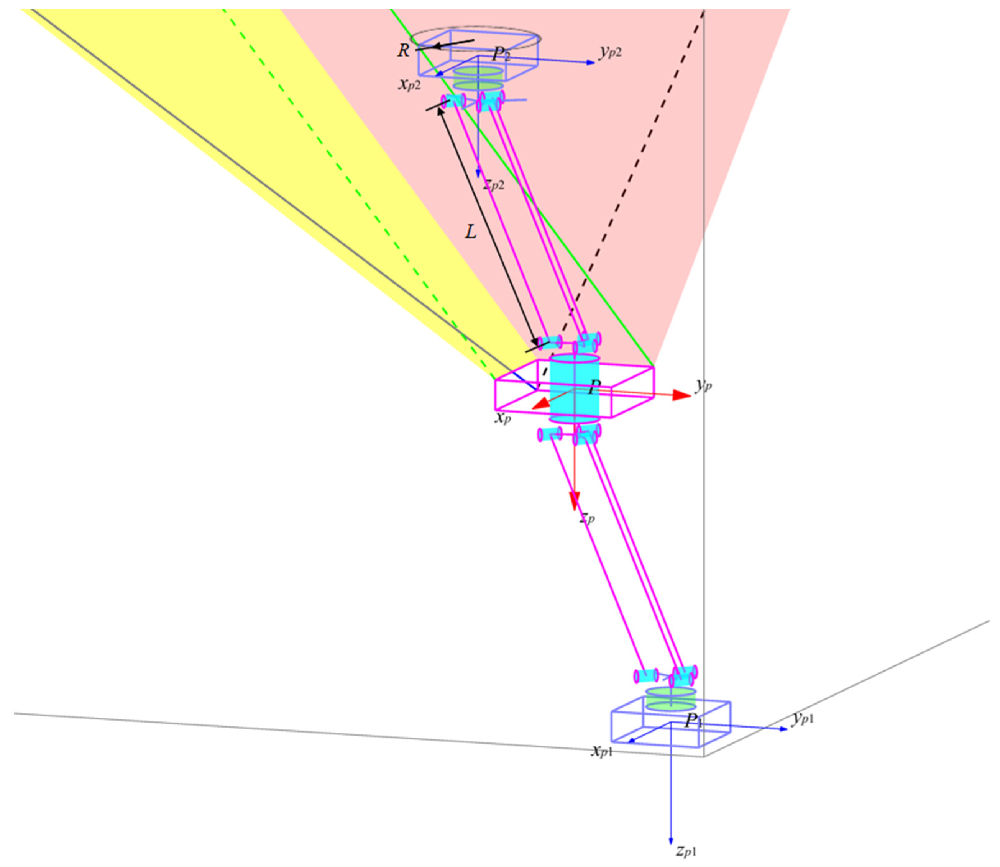
2.1. Rigid–Flexible Robot Geometric Model

This paper presents a rigid–flexible robotic system that consists of a CDPR in series with a framework-type manipulator arm. The CDPR is driven by four sets of parallel cables, and the moving platform of the CDPR achieves three degrees of translational freedom in space. The framework-type manipulator arm with two rotational degrees of freedom is installed on the moving platform of the CDPR. The working direction is adjusted by the rotating arm, and the upper and lower arms break through the workspace of the CDPR to perform the spraying task. A schematic of the mechanism is shown in Figure 3. In the figure, O is a reference point on the inner cabin wall of the oil tanker; A 1 to A 8 are the anchor points of the cables on the moving platform; B 1 to B 8 are the cable exit points within the tanker cabin; P is the center of the moving platform, which is also the hinge center of the rotating arm and the moving platform; C 1 is the center of the short rod connecting the upper arm parallelogram mechanism to the rotating arm; P 1 is the center of the short rod connecting the upper arm parallelogram mechanism to the upper-end platform; C 2 is the center of the short rod connecting the lower arm parallelogram mechanism to the rotating arm; P 2 is the center of the short rod connecting the lower arm parallelogram mechanism to the lower end platform.
The CDPR uses four sets of parallel cable drives ( A 1 B 1 / A 2 B 2 , A 3 B 3 / A 4 B 4 , A 5 B 5 / A 6 B 6 , and A 7 B 7 / A 8 B 8 ). Each set of parallel cables shares a single drive, synchronously winding and unwinding. The four sets of parallel cables can constrain the moving platform’s three rotational degrees of freedom. During operation, the parallel cables ensure that the moving platform remains level. The upper and lower arms of the framework-type manipulator arm are symmetrically mounted on the rotating arm and share a single drive. The gravitational forces of the upper and lower arms counterbalance each other, reducing the holding torque and energy consumption during rotation.
At the end platform, an electromagnetic suction device is installed to improve the stiffness of the entire system during the spraying operation and prevent vibration. A lightweight specialized coating device is also installed to realize the specialized coating of the inner walls.
During specialized coating, the CDPR first moves to the boundary of the workspace. The rotating arm adjusts the working position, and the upper or lower arm extends out of the workspace of the CDPR. The end platform is attracted to the wall surface, and the specialized coating equipment mounted on the end platform performs specialized coating within the range.
Figure 4 shows the design of the cable driving component and the framework-type parallelogram mechanism component of the rigid–flexible robotic system. For other components of the rigid–flexible robotic system, such as CDPR, rotary motor, etc., there is mature design, so this paper mainly introduces the unique design of the cable driving component and the framework-type parallelogram mechanism component.
The cable driving component is composed of a fixed part, a driving motor, a drum, a sliding block and a fitting pulley. The motor drives the drum to retract and retract the cable. When the length of the cable is different, the tangential position of the cable and the drum also changes. The slide block drives the fitting pulley to move on the slide rail, so as to ensure that the cable always follows the direction of a guide groove on the drum and prevent the cable from moving away from the guide groove.
The parallelogram mechanism component adopts the frame structure and consists of many identical rods. The advantage of this design is that, when transported, it can be folded up to take up very little space; it would otherwise be difficult to transport with an arm longer than 4 m. When working, the rods are spread out and their joints are fixed, which does not give the robot additional uncontrollable degrees of freedom.

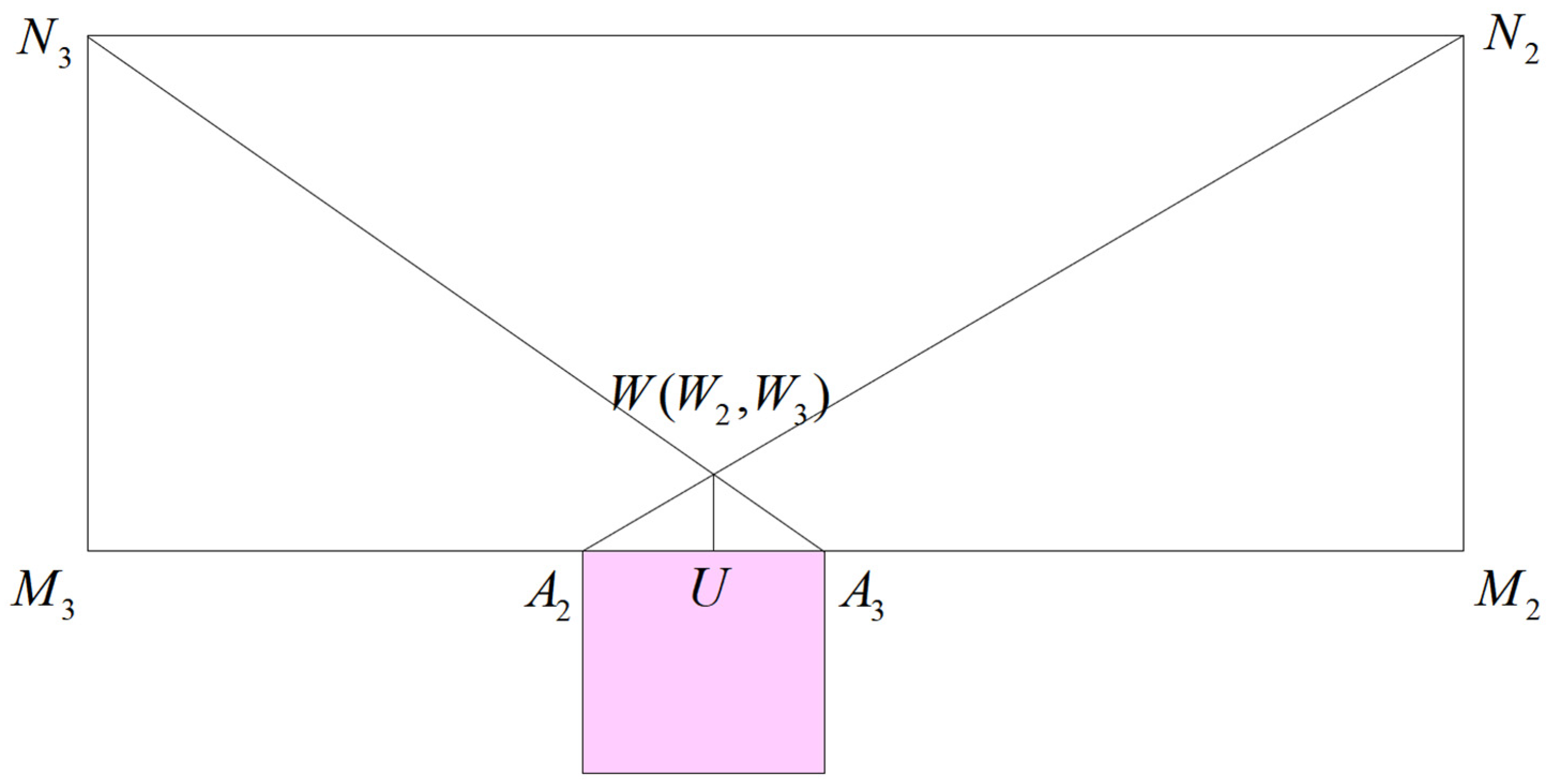
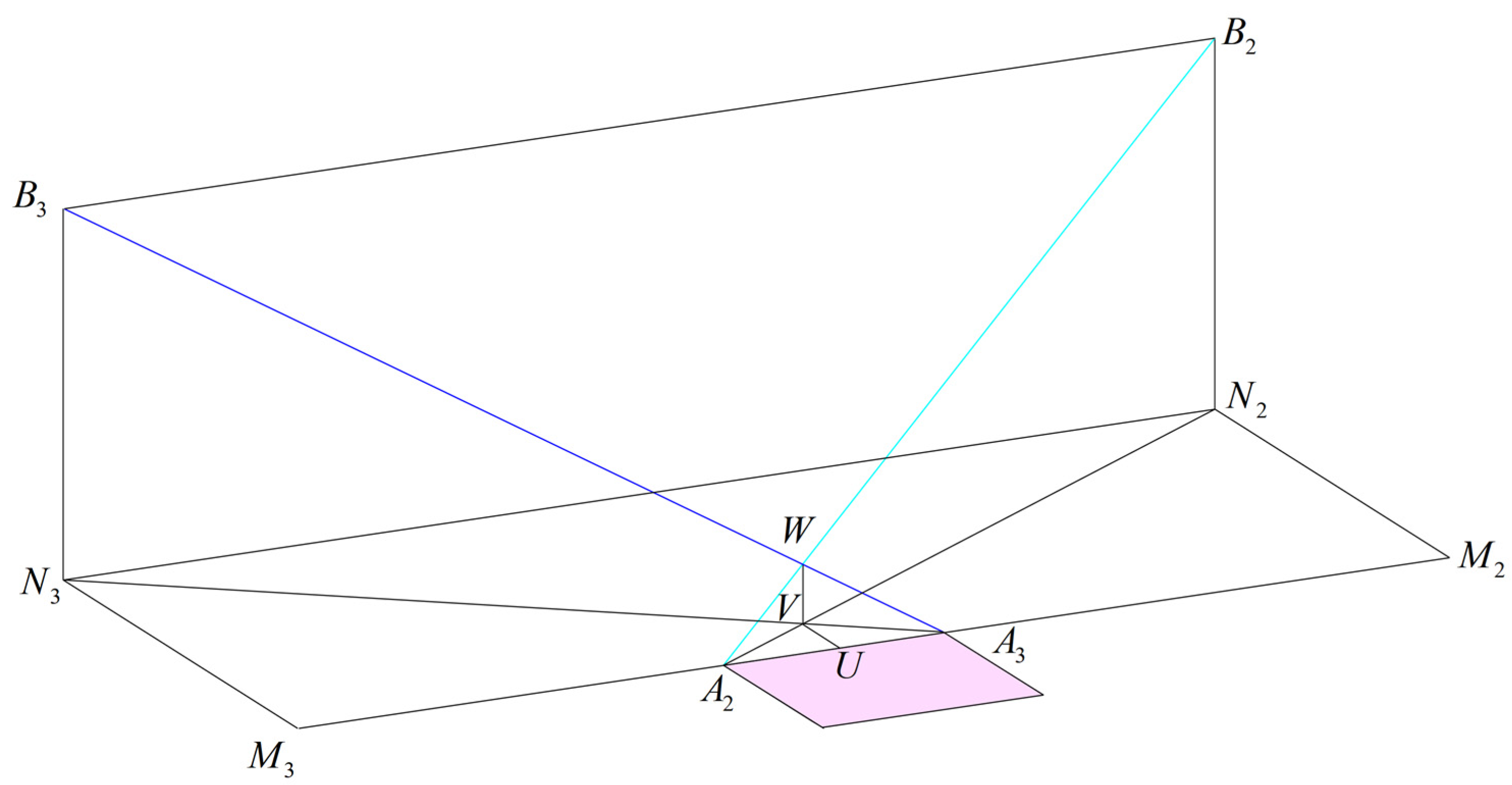
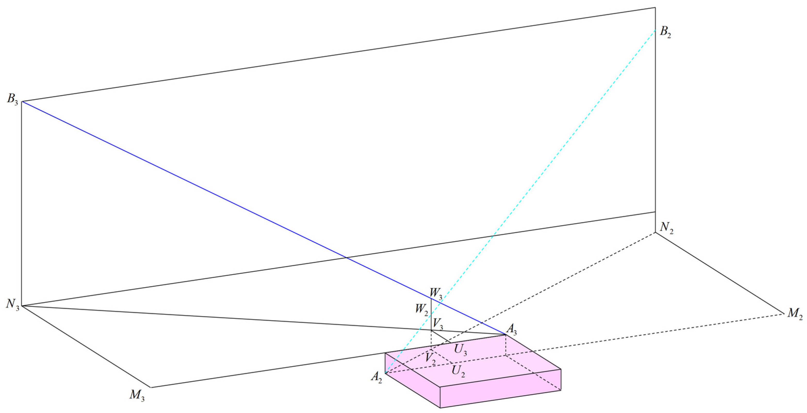
2.2. Cable Interference Analysis

Each set of parallel cables of the CDPR has symmetric anchor points about the center of the moving platform within the horizontal plane. If all cable anchor points are arranged in the same plane, different parallel cable sets will intersect. Taking cables A 2 B 2 and A 3 B 3 as an example, as shown below in Figure 5, points A 2 N 2 and A 3 N 3 are the projections of the two cables on the horizontal plane; point V is the intersection of the two cable projections on the horizontal plane; point U is the projection of point V on the line A 2 A 3 .
Due to the constraint of parallel cables, the moving platform remains level and its sides are parallel to the corresponding sides in space. Therefore, we have:
N 2 M 2 / / V U / / N 3 M 3 ,   N 2 M 2 = N 3 M 3 N 2 B 2 / / V W 2 ( 3 ) / / N 3 B 3 ,   N 2 B 2 = N 3 B 3
By using similar triangles (Figure 6), we can derive:
V W 2 N 2 B 2 = A 2 V A 2 N 2 = V U N 2 M 2 V W 3 N 3 B 3 = A 3 V A 3 N 3 = V U N 3 M 3
Thus,
V W 2 = V W 3
This means that points W 2 and W 3 coincide at W , and the two cables intersect in space, leading to wear during the moving platform’s motion.
Based on the above analysis, lowering the cable exit and anchor points of cable A 2 B 2 can ensure that cable A 2 B 2 is always below cable A 3 B 3 , as shown in Figure 6. The vertical height difference in the horizontal plane projection positions is:
W 2 W 3 = V 2 V 3 = h
where h is the vertical height difference between the two cable anchor points. To prevent wear between the cables, the vertical height difference between the cables must be at least five times the cable diameter d . Therefore, the height difference requirement for the cable anchor points on the moving platform is h ≥ 5 d .

3. Motion and Force Analysis of the Cable-Parallel Robot

3.1. Motion Analysis

A global coordinate system O x y z is established at point O , and a moving platform coordinate system P x p y p z p is established at point P , with the directions of each coordinate axis shown in Figure 3. The vector of each cable is denoted as A i B i = l i ( i = 1 , 2 , , 8 ) , the corresponding unit direction vector as e i , the position vector of each cable exit point as O B i = b i in the global coordinate system, the position vector of each cable anchor point as P A i = a i , and the position vector of the moving platform as O P = p .
For the i -th branch of the driving system, the vector closure equation is:
O P = O B i + B i A i + A i P O P 1 = O P + P C 1 + C 1 P 1 O P 2 = O P + P C 2 + C 2 P 2
The corresponding vector l i for the i -th cable can be obtained as:
l i = b i a i p
The corresponding unit direction vector e i is e i = l i / | l i | .

3.2. Static Force Analysis

During the special coating process, the moving platform remains stationary or moves at a low speed, so only static analysis of the cable-parallel robot is required. In a stationary or uniform speed state, without considering external force disturbances, the sum of the cable forces on the moving platform, the gravity of the moving platform, and the frame-type robotic arm are mutually balanced. According to Newton’s second law, the force balance equation of the moving platform is:
i = 1 8 f i + m g = 0
where m is the total mass of the moving platform, framework-based mechanical arm, and end platform, and g = [ 0   0   9.8 N / m ] T is the acceleration due to gravity.
The frame-type robotic arm is symmetrically installed, and the torques caused by the gravity of the upper and lower arms are mutually balanced. If there is no offset of the center of gravity and external torque on the moving platform, the torques generated by the cable forces acting on the moving platform need to be mutually balanced. The torque balance equation for the centroid of the moving platform is:
i = 1 8 a i × f i = 0
Since the cable can only provide tension and cannot be broken, there is a constraint on the cable force:
0 f i f max ,   i = 1 , 2 , , 8
To ensure the controllability of the six degrees of freedom of the macro platform, at most two cables can be slacked. Therefore, a constraint is imposed on the third smallest cable force among the eight cable forces:
f min 3 f min
where f min 3 is the third smallest cable force among the eight cable forces.

4. Workspace Analysis of the Cable-Parallel Robot

4.1. Reachable Workspace Analysis

Since the CDPR is constrained by eight cables, the cable force is redundant, and in most cases, there are multiple solutions for cable force. The close-form method can solve cable force based on the 2-norm of the cable force matrix and other goals. However, this method does not constrain the maximum and minimum cable forces, and it can only verify the cable force constraints after solving the cable force. Therefore, the close-form method can only solve a subspace of the real workspace of the CDPR [11].
To obtain the maximum workspace, this paper uses the minimum 2-norm value of the cable force array as the objective value, combines the static equilibrium equation constraints and the cable force inequality constraints, and solves the cable force using an active-set optimization algorithm.
The mathematical model is expressed as follows:
min f 2 i = 1 8 f i + m g = 0 s . t .   i = 1 8 a i × f i = 0 0 f i f max ,   i = 1 , 2 , , 8 f min 3 f min
where f = [ f 1 f 8 ] T is the cable force array.
This paper selects a tanker inner cabin space with dimensions of 35 m × 40 m × 30 m. The parameters of the cable-parallel robot are shown in Table 1. The reachable workspace of the cable-parallel robot is shown in Figure 7.
The reachable workspace of the CDPR occupies 69.95% of the physical space, and the regular workspace is a rectangular space of 28.5 m × 33.5 m × 27 m, occupying 59.4% of the physical space. The top surface of the regular workspace is 3 m away from the top surface of the tanker’s inner cabin, and the side surface is 3.25 m away from the side surface of the tanker’s inner cabin. When z < 10 m, the top regular workspace expands to a rectangular space of 31 m × 36 m × 7 m, with the side surface of the top regular workspace 2 m away from the side surface of the tanker’s inner cabin.

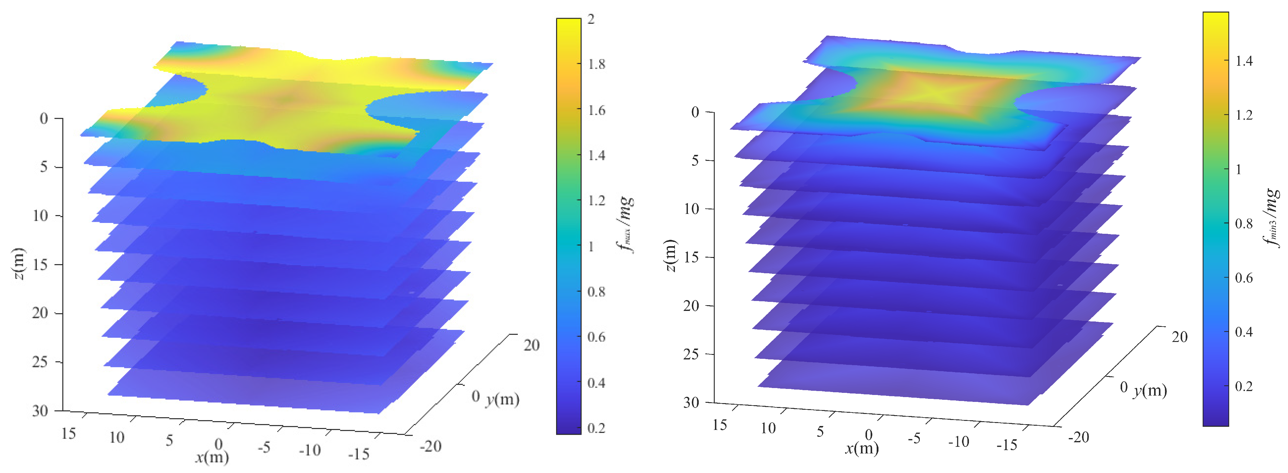
4.2. Cable Force Analysis

The z-direction slice maps of the maximum cable-force-to-gravity ratio and the third smallest cable-force-to-gravity ratio in the reachable workspace are shown in Figure 8.
As the distance between the moving platform and the central axis of the space increases, the maximum values of each cable force gradually increase. In particular, at the bottom of the space, the cable force increases fastest along the direction from the midpoint to the cable output point. At the top of the space, the cable force increases fastest along the direction from the center to the midpoint of the horizontal edge. At the top of the space, due to the cables’ mutual pulling, the pulling cables’ tension increases sharply, and at the same time, all cable forces are slightly elevated. At the boundary of the top workspace, the maximum cable force reaches the limit of twice the gravity, and the third most minor cable force also reaches 1.4 times the gravity. Outside the top workspace, the maximum cable force exceeds the limit, resulting in unreachability.
As the moving platform height decreases and the distance from the space center increases, the third smallest values of each cable force gradually decrease. Therefore, as the distance from the top surface increases, the outer periphery of the moving platform workspace gradually contracts, and the distance from the workspace boundary to the side wall gradually increases. At the side and corner of the space, the platform gravity is mainly borne by one to two groups of closer cables, causing uneven distribution of cable forces. At the boundary of the corner workspace, the maximum single cable force is still close to 0.5 times the gravity, the farthest cable becomes slack, and the farther cable has only 0.05 times the gravity. More than two cables become slack outside the workspace, resulting in unreachability.
When the moving platform has a certain distance from the top surface of the space and is not at the center of the space, the platform gravity is mainly borne by the three closer groups of parallel cables forming the 6-CSPR mechanism. In contrast, the farther group of parallel cables has smaller forces. When approaching the workspace boundary, the farther group of cables becomes slack.
Near the midpoint of the workspace slice boundary, the two farther groups of cable output points have similar distances to the moving platform, and their cable directions are also symmetrical. Currently, without increasing the cable force constraints, the solution method with the 2-norm of the cable force matrix as the goal will result in almost equal forces for the two groups of cables, causing the forces to be evenly distributed and both groups of cables to become slack. However, this position is still within the workspace because the eight cables can redistribute the forces, making the geometrically symmetrical cable forces unevenly distributed. At this point, one group of cables becomes slack while the other does not, and the position is reachable. In the above position, the feasible solution set of cable forces is discontinuous, so the workspace obtained by the optimization algorithm has discontinuous cable force distribution near this position. Also, when the moving platform moves continuously near this position, the cable forces may be discontinuous, potentially causing an impact on the moving platform and motors.

5. Dimensional Analysis of the Frame-Type Manipulator

From the workspace analysis of the cable-parallel robot, it can be concluded that the unreachable areas at the top (3 m) and sides (2–3.25 m) need to be compensated for by the frame-type manipulator. The parameters of the frame-type manipulator used in this paper are shown in Table 2.

5.1. Rapid Search Method for Feasible Posture and End-Effector-Reachable Workspace of Rigid–Flexible Robotic System

Since the cable-parallel robot’s moving platform has three degrees of freedom, the frame-based robotic arm has two degrees of freedom, and the end platform requires three translational degrees of freedom, the rigid–flexible robotic system is redundant in degrees of freedom. This means that for any point in the reachable workspace on the wall, the feasible posture of the rigid–flexible robotic system is often not unique.
The feasible posture of the rigid–flexible robotic system is formed by coupling the feasible workspace of the cable-parallel robot and the workspace of the frame-based robotic arm. The workspace of the frame-based robotic arm’s end platform is mainly constrained by the interference of the upper arm and the cable. Considering the upper arm as a cylinder with a radius of 750 mm and using the condition that the vertical distance between the frame-based robotic arm’s axis and the cable is greater than or equal to 750 mm, the reachable workspace on the upper and side walls for the end platform (i.e., the terminal reachability of the rigid–flexible robotic system) was searched for.
When the upper arm performs the spraying task, it needs to extend out of the workspace of the cable-parallel robot. At this time, the positional relationship between the upper arm and the cable is complex. In the projection of the feasible posture in the x or y direction, the angle between the upper arm and the moving platform must be smaller than the angle between the cable and the moving platform. However, when the lower arm performs the spraying task, it needs to extend out of the workspace of the cable-parallel robot, and the upper arm may not necessarily extend out of the workspace of the cable-parallel robot. In the projection of the feasible posture in the x or y direction, the angle between the upper arm and the moving platform may be larger than the angle between the cable and the moving platform. Therefore, a simplified interference analysis method was proposed for the case where the lower arm performs the spraying task to speed up the workspace search.
Due to the symmetry of the space, only the analysis of the O x + y + z region was conducted. To simplify the calculation and quickly determine the feasible posture, the plane formed by the upper cable and the corresponding edge of the moving platform on the opposite side was used to replace the cable for interference analysis. The x alternative plane on the opposite side in the x + direction is shown by the red shading in Figure 9, and the y alternative plane on the opposite side in the y + direction is shown by the yellow shading in Figure 9. The angle between the x alternative plane and the horizontal plane is:
θ x = arctan ( l 5 z / l 5 x )
where l 5 x and l 5 z are the x and z components of l 5 , respectively.
Similarly, the angle between the y alternative plane and the horizontal plane is:
θ y = arctan ( l 6 z / l 6 x )
where l 6 x and l 6 z are the x and z components of l 6 , respectively.
The projections of the connection points of the upper and lower arms with the rotating arm on the horizontal plane will not exceed the range of the moving platform. Therefore, when the rotating arm and the upper and lower arms of the frame-based robotic arm rotate, the upper and lower arm links are at most parallel to the alternative plane, which can fully ensure that the frame-based robotic arm will not interfere with the cable. The maximum rotation angle of the upper arm constrained by the two alternative planes is:
θ 2 max x = arctan ( 1 / cos ( θ 1 ) tan ( θ x ) ) θ 2 max y = arctan ( 1 / cos ( π / 2 + θ 1 ) tan ( θ y ) ) θ 2 max = min ( θ 2 max x   θ 2 max y )
where θ 1 [ π / 2 ,   π / 2 ] is the rotation angle of the rotating arm, and θ 2 max is the maximum value of the upper arm rotation angle determined by this method that will not cause interference. The rotation angle θ 2 is 0 when the upper arm is vertical.
In fact, θ 2 max ( θ 1 ) provides a boundary for a pyramidal regular workspace of the frame-based robotic arm, which can be used to quickly determine the possible feasible posture of the robot and speed up the search for the frame-based robot workspace.
Therefore, the search strategy for the end-effector-reachable workspace of the rigid–flexible robotic system is given as follows:
Step 1: Select a search point p = [ x , y , z ] on the wall surface and perform Steps 2–4 until the entire space search is completed.
Step 2: Determine the robotic arm performing the spraying task. When z < 10 m, the upper arm performs the spraying task; when z ≥ 10 m, the lower arm performs the spraying task.
Step 3: When the upper arm performs the spraying task, search θ 1 : 0 ± π / 2 ,   θ 2 : 0 π / 2 ; when the lower arm performs the spraying task, search θ 1 : 0 ± π / 2 ,   θ 2 : 0 θ 2 max .
Step 4: For the situation where the lower arm performs the spraying task, if Step 3 does not find a feasible posture, search θ 1 : 0 ± π / 2 ,   θ 2 : θ 2 max π / 2 .

5.2. End-Effector-Reachable Workspace Analysis of the Rigid–Flexible Robotic System

Using the search method proposed in Section 5.1, the end-effector-reachable workspace of the rigid–flexible robotic system for different link lengths and end platform radius R is obtained as shown in Table 3, where gray represents the reachable workspace and red represents the unreachable area.
According to Table 3, as the end platform radius and link length increase, the reachable workspace of the rigid–flexible robot terminal on the tanker inner wall gradually increases. When the end platform radius R = 1000 mm and link length L = 5000 mm, all wall surfaces are reachable. When the end platform radius R < 1000 mm and link length L < 5000 mm, the unreachable areas of the rigid–flexible robot are concentrated at the corners and top corners of the side walls. In the top part of the space, the unreachable areas are distributed along the cable direction, mainly affected by the interference between the cable and the corresponding-wall-side cable. In the middle and lower parts of the space, the distance from the wall corner to the nearest moving platform workspace reaches 4.6 m, so the length of the upper and lower arms have a significant impact on the size of the unreachable area in this part.
In the special coating application of the rigid–flexible robotic system proposed in this paper, it is necessary to set up scaffolding at the side wall corners or use wall-climbing robots to install and dismantle the cable-parallel robot’s cable pulley at the side wall corners. Therefore, for a 35 m × 40 m × 30 m tanker inner cabin, an end platform with R = 750 mm and a link with L = 4500 mm can be used to complete the special coating tasks for the top and side walls of the tanker inner cabin, and to respray the corners, top corners, and equipment installation areas during dismantling.
In summary, this section proposes a partially simplified cable interference analysis method based on the interference between the frame-based robotic arm and the cable, speeding up the search for the reachable workspace of the rigid–flexible robot end platform. For different size parameters of the frame-based robotic arm, the reachable workspace of the rigid–flexible robot end platform was searched and analyzed, verifying the terminal reachability of the rigid–flexible robotic system and providing a basis for the size selection of the rigid–flexible robotic system in practical applications.

6. Conclusions

This paper proposed a conceptual rigid–flexible robot system using a cable-parallel robot in series with a frame-type manipulator for large-span special coating on the inner wall of a finished tanker cabin. It established the kinematic and static models of the cable-parallel robot. The interference and wear problems of cross cables were analyzed. A solution with staggered cable anchor points in the height direction was adopted to avoid interference problems of cross cables. Based on the minimum 2-norm of the cable force array, the cable force of the cable-parallel robot was solved using an optimization method, and the workspace of the moving platform was obtained. Considering the interference problem under different postures of the cable-parallel robot, the dimensions of the frame-type manipulator were analyzed, providing a basis for robot size selection in practical applications, and verifying the terminal reachability of the rigid–flexible robot system.
This paper solves the critical problem of applying CDPRs to the spraying of the inner wall of a finished tanker cabin, achieves the terminal reachability of the rigid–flexible robot system, and expands the reachable workspace of the robot to coincide with the inner cabin space of the tanker, covering all areas to be sprayed. This paper solves the problems of high cost, long time cycle, and poor safety of the traditional method of building scaffolding for manual spraying. It provides a new automated solution for special coating in the inner cabins of finished tankers.
In conclusion, this study has addressed the challenges of using CDPRs for special coating applications in finished tanker cabins. By designing a rigid–flexible robot system that combines a cable-parallel robot with a frame-type manipulator, the terminal reachability of the system has been achieved, ensuring that all areas requiring coating can be covered. This approach overcomes the limitations of traditional manual spraying techniques that rely on scaffolding, which are costly, time-consuming, and pose safety risks. As a result, this paper presents an innovative automated solution for special coating applications in finished tanker cabins.

Author Contributions

Conceptualization, J.Q. and Y.M.; methodology, J.Q. and Y.M.; investigation, T.H., H.L., Z.S. and D.C.; writing—original draft preparation, J.Q.; writing—review and editing, Y.M. and H.L. All authors have read and agreed to the published version of the manuscript.

Funding

This work was supported in part by the National Natural Science Foundation of China (Grant Nos. U19A20101 and 52105025).

Institutional Review Board Statement

Not applicable.

Informed Consent Statement

Not applicable.

Data Availability Statement

Not applicable.

Conflicts of Interest

The authors declare no conflict of interest.

References

  1. An, H.G. Research on the Tank Coating Techniques Optimization for the Product Oil Tanker. Master’s Thesis, Dalian University of Technology, Dalian, China, 2019. [Google Scholar] [CrossRef]
  2. Zhang, Z.; Shao, Z.; Wang, L. Optimization and implementation of a high-speed 3-DOFs translational cable-driven parallel robot. Mech. Mach. Theory 2020, 145, 103693. [Google Scholar] [CrossRef]
  3. Zhang, Z.; Shao, Z.; Wang, L.; Shih, A.J. Optimal Design of a High-Speed Pick-and-Place Cable-Driven Parallel Robot. In Cable-Driven Parallel Robots; Gosselin, C., Cardou, P., Bruckmann, T., Pott, A., Eds.; Mechanisms and Machine Science; Springer: Cham, Switzerland, 2018; Volume 53. [Google Scholar] [CrossRef]
  4. Shao, Z.F.; Tang, X.Q.; Chen, X.; Wang, L.-P. Driving force analysis for the secondary adjustable system in FAST. Robotica 2011, 29, 903–915. [Google Scholar] [CrossRef]
  5. Gosselin, C. Cable-driven parallel mechanisms: State of the art and perspectives. Mech. Eng. Rev. 2014, 1, DSM0004. [Google Scholar] [CrossRef]
  6. Tang, X. An overview of the development for cable-driven parallel manipulator. Adv. Mech. Eng. 2014, 6, 823028. [Google Scholar] [CrossRef]
  7. Zi, B.; Duan, B.Y.; Du, J.L.; Bao, H. Dynamic modeling and active control of a cable-suspended parallel robot. Mechatronics 2008, 18, 1–12. [Google Scholar] [CrossRef]
  8. Ming, A. Study on multiple degree-of-freedom positioning mechanism using wires (part 1). Int. J. Jpn. Soc. Precis. Eng. 1994, 28, 131–138. [Google Scholar]
  9. Bostelman, R.; Albus, J.; Dagalakis, N.; Jacoff, A.; Gross, J. Applications of the NIST RoboCrane. In Proceedings of the 5th International Symposium on Robotics and Manufacturing, Maui, HI, USA, 14–18 August 1994; Volume 5, p. 1. [Google Scholar]
  10. Lamaury, J.; Gouttefarde, M. Control of a large redundantly actuated cable-suspended parallel robot. In Proceedings of the 2013 IEEE International Conference on Robotics and Automation, Karlsruhe, Germany, 6–10 May 2013; pp. 4659–4664. [Google Scholar] [CrossRef]
  11. Caro, S.; Merlet, J.P. Failure analysis of a collaborative 4-1 cable-driven parallel robot. In New Trends in Mechanism and Machine Science; EuCoMeS 8; Springer International Publishing: Cham, Switzerland, 2020; pp. 440–447. [Google Scholar] [CrossRef]
  12. Alp, A.B.; Agrawal, S.K. Cable suspended robots: Design, planning and control. In Proceedings of the 2002 IEEE International Conference on Robotics and Automation (Cat. No. 02CH37292), Washington, DC, USA, 11–15 May 2002; Volume 4, pp. 4275–4280. [Google Scholar] [CrossRef]
  13. Gouttefarde, M.; Merlet, J.P.; Daney, D. Determination of the wrench-closure workspace of 6-DOF parallel cable-driven mechanisms. In Advances in Robot Kinematics: Mechanisms and Motion; Springer: Dordrecht, The Netherlands, 2006; pp. 315–322. [Google Scholar] [CrossRef]
  14. Gouttefarde, M.; Gosselin, C.M. Analysis of the wrench-closure workspace of planar parallel cable-driven mechanisms. IEEE Trans. Robot. 2006, 22, 434–445. [Google Scholar] [CrossRef]
  15. Bosscher, P.; Riechel, A.T.; Ebert-Uphoff, I. Wrench-feasible workspace generation for cable-driven robots. IEEE Trans. Robot. 2006, 22, 890–902. [Google Scholar] [CrossRef]
  16. Pusey, J.; Fattah, A.; Agrawal, S.; Messina, E. Design and workspace analysis of a 6–6 cable-suspended parallel robot. Mech. Mach. Theory 2004, 39, 761–778. [Google Scholar] [CrossRef]
  17. Gouttefarde, M.; Merlet, J.P.; Daney, D. Wrench-feasible workspace of parallel cable-driven mechanisms. In Proceedings of the 2007 IEEE International Conference on Robotics and Automation, Rome, Italy, 10–14 April 2007; pp. 1492–1497. [Google Scholar] [CrossRef]
  18. Nurahmi, L.; Pramujati, B.; Caro, S.; Jeffrey. Dimension synthesis of suspended eight cables-driven parallel robot for search-and-rescue operation. In Proceedings of the 2017 International Conference on Advanced Mechatronics, Intelligent Manufacture, and Industrial Automation (ICAMIMIA), Surabaya, Indonesia, 12–14 October 2017; pp. 237–241. [Google Scholar] [CrossRef]
  19. Handojo, V.A.; Syamlan, A.T.; Nurahmi, L.; Pramujati, B.; Tamara, M.N.; Wasiwitono, U. Cable driven parallel robot with big interference-free workspace. In Mechanism and Machine Science: Select Proceedings of Asian MMS 2018; Springer: Singapore, 2020; pp. 43–56. [Google Scholar] [CrossRef]
  20. Castelli, G.; Ottaviano, E.; González, A. Analysis and simulation of a new Cartesian cable-suspended robot. Proc. Inst. Mech. Eng. Part C J. Mech. Eng. Sci. 2010, 224, 1717–1726. [Google Scholar] [CrossRef]
  21. Barrette, G.; Gosselin, C.M. Determination of the dynamic workspace of cable-driven planar parallel mechanisms. J. Mech. Des. 2005, 127, 242–248. [Google Scholar] [CrossRef]
  22. Gosselin, C.; Ren, P.; Foucault, S. Dynamic trajectory planning of a two-DOF cable-suspended parallel robot. In Proceedings of the 2012 IEEE International Conference on Robotics and Automation, Saint Paul, MN, USA, 14–18 May 2012; pp. 1476–1481. [Google Scholar] [CrossRef]
  23. Longval, J.M.; Gosselin, C. Dynamic trajectory planning and geometric design of a two-DOF translational cable-suspended planar parallel robot using a parallelogram cable loop. In International Design Engineering Technical Conferences and Computers and Information in Engineering Conference; American Society of Mechanical Engineers: New York, NY, USA, 2018; Volume 51814, p. V05BT07A030. [Google Scholar] [CrossRef]
  24. Gosselin, C. Global planning of dynamically feasible trajectories for three-DOF spatial cable-suspended parallel robots. In Cable-Driven Parallel Robots; Springer: Berlin/Heidelberg, Germany, 2013; pp. 3–22. [Google Scholar] [CrossRef]
  25. Jiang, X.; Gosselin, C. Dynamically feasible trajectories for three-dof planar cable-suspended parallel robots. In International Design Engineering Technical Conferences and Computers and Information in Engineering Conference; American Society of Mechanical Engineers: New York, NY, USA, 2014; Volume 46360, p. V05AT08A085. [Google Scholar] [CrossRef]
  26. Zoso, N.; Gosselin, C. Point-to-point motion planning of a parallel 3-dof underactuated cable-suspended robot. In Proceedings of the 2012 IEEE International Conference on Robotics and Automation, Saint Paul, MN, USA, 14–18 May 2012; pp. 2325–2330. [Google Scholar] [CrossRef]
  27. Jiang, X.; Barnett, E.; Gosselin, C. Dynamic point-to-point trajectory planning beyond the static workspace for six-DOF cable-suspended parallel robots. IEEE Trans. Robot. 2018, 34, 781–793. [Google Scholar] [CrossRef]
  28. Xiang, S.; Gao, H.; Liu, Z.; Gosselin, C. Trajectory Optimization for a Six-DOF Cable-Suspended Parallel Robot with Dynamic Motions Beyond the Static Workspace. In Proceedings of the 2020 IEEE International Conference on Robotics and Automation (ICRA), Paris, France, 31 May–31 August 2020; pp. 3903–3908. [Google Scholar] [CrossRef]
Figure 1. Manual operation of special coating. (a) Full warehouse scaffolding; (b) hanging scaffolding.
Jmse 11 01063 g001
Figure 2. CDPR’s statically reachable workspace [11]. (Four cables, particle moving platform; purple represents accessible workspace).
Jmse 11 01063 g002
Figure 3. Schematic of the rigid–flexible robotic system.
Jmse 11 01063 g003
Figure 4. The 3D models of the cable driving component and the framework-type parallelogram mechanism component.
Jmse 11 01063 g004
Figure 5. Schematic of cable intersection.
Jmse 11 01063 g005aJmse 11 01063 g005b
Figure 6. Schematic of cable intersection (similar triangles).
Jmse 11 01063 g006
Figure 7. Reachable workspace of the macro robot.
Jmse 11 01063 g007
Figure 8. Z-direction slice maps of cable forces for the CDPR.
Jmse 11 01063 g008
Figure 9. Schematic diagram of simplified alternative planes for cable interference.
Jmse 11 01063 g009
Table 1. Macro robot parameter table (cable-parallel robot).
ParametersNumerical Value
Macro platform length2000 mm
Macro platform width2000 mm
Macro platform height (anchor point height difference)10 mm
Parallel cable spacing3464 mm
Total mass of macro platform, micro platform, and end effector100 kg
Minimum cable force limit (multiple of gravity)0.05
Maximum cable force limit (multiple of gravity)2
Table 2. Macro robot parameter table (frame-type manipulator).
ParametersNumerical Value
Maximum upper arm radius750 mm
Maximum lower arm radius750 mm
Short rod position PC connecting the upper and lower arms to the rotating arm100 mm
Upper and lower arm length CPL
End platform radiusR
Table 3. End-effector-reachable workspace of the rigid–flexible robotic system with different dimensions of the frame-based robotic arm.
End Platform Radius R (mm)7501000
Upper and
Lower Arm
Length L (mm)
4000Jmse 11 01063 i001Jmse 11 01063 i002
4500Jmse 11 01063 i003Jmse 11 01063 i004
5000Jmse 11 01063 i005Jmse 11 01063 i006
Disclaimer/Publisher’s Note: The statements, opinions and data contained in all publications are solely those of the individual author(s) and contributor(s) and not of MDPI and/or the editor(s). MDPI and/or the editor(s) disclaim responsibility for any injury to people or property resulting from any ideas, methods, instructions or products referred to in the content.

