
Influence of Firefighting Intervention on Fire Spread Characteristics in Ship Engine Room


1
College of Shipbuilding Engineering, Harbin Engineering University, Harbin 150001, China
2
International Joint Laboratory of Naval Architecture and Offshore Technology between Harbin Engineering University and Lisbon University, Harbin 150001, China
*
Author to whom correspondence should be addressed.
J. Mar. Sci. Eng. 2023, 11(4), 877; https://doi.org/10.3390/jmse11040877
Submission received: 27 March 2023
/
Revised: 11 April 2023
/
Accepted: 13 April 2023
/
Published: 21 April 2023
(This article belongs to the Special Issue Selected Papers from MARTECH 2022, the 6th International Conference on Maritime Technology and Engineering)
Abstract
:The purpose of this paper is to investigate and evaluate the ship engine room fire spreading characteristics based on the effect of firefighting interventions. The large eddy simulation (LES) and theoretical models are employed to simulate a fire scene in the engine room. The fire spreading characteristics and the mechanism of the use of a fine water mist are obtained by varying the ventilation conditions and parameters of the water sprinkler. The results show that the reason why a pool fire can be more easily extinguished as the spray speed increases is because the water mist with a higher spray speed has a larger spray area. Meanwhile, the temperature in the engine room would drop more rapidly with the increasing spray area due to the higher evaporation rate. Furthermore, the arrangement of the ventilation conditions had an obvious effect on the fire spreading characteristics, as the depletion of the combustion medium affects the combustion situation.
1. Introduction
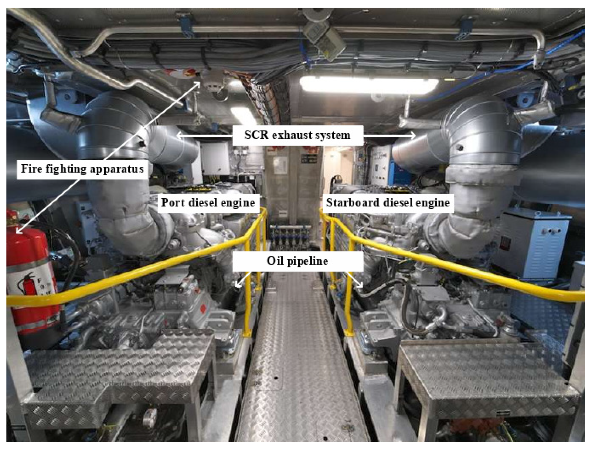
The engine room fire is one of the main types of ship accidents. The engine room has a high probability of fire due to the dense arrangement of oil piping, numerous combustible materials, and restricted space and narrow passages. Once a fire occurs, it spreads quickly and is difficult to put out, and the safety of people and property is seriously threatened. The design of sprinkler systems is generally based on the requirements of the fire code.
Once a fire occurs in a ship, it is necessary to consider the effectiveness of the fire extinguishing medium interacting with the fire according to the combustion properties of the fire source, and then measures should be taken such as launching automated water sprinklers or releasing a carbon dioxide extinguishing agent or sealing the cabin vents to ensure the safety of personnel and property. Among them, automated water sprinklers are widely used in various fields due to their many advantages such as high efficiency, stability, low cost, sustainability, and environmental-friendliness. The use of water sprinkler systems in enclosed spaces has been studied since the 1960s, and most of the research in this area were experiment based. Cooper et al. [1,2] were the first to investigate the mechanism of smoke movement under sprinkler action and proposed an empirical formulation of the sprinkler model. Ingason et al. [3] conducted a large number of full-scale experiments to study the interaction between sprinkler and smoke exhaust systems under different fire environmental conditions by varying the fire growth and smoke exhaust methods. McGrattan et al. [4] conducted several full-scale experiments to explore the interaction of water sprinklers, smoke extraction, and other measures in similar large warehouses and plants in the event of fire, and refined their numerical calculation software FDS (Fire Dynamic Solution) based on the experimental results. Braun et al. [5] constructed diesel and polyethylene pellet fire experiments at different heat release powers to analyze and evaluate the effectiveness of smoke extraction systems by comparing the FDS numerical simulation results with the data obtained in four large shipboard fire tests. The results showed that the environmental parameters of the compartment corridor close to the fire source can be brought to survival conditions by isolating the fire compartment and adjacent space ventilation. According to the diversity of pool fires, Raj et al. [6], Tao et al. [7], and Leite et al. [8] studied the geometric and radiation characteristics of oil pool fires by varying the size, shape, and location of the oil pools.
For the completely closed cabin fire, Utiskul et al. [9] studied the heptane pool fire in a small-scale cabin, and found the influence of ventilation on the extinction and oxygen concentration. Pearson [10] studied the combustion phenomenon when the fire source was located in the upper part of the cabin. For the study of ship fires, Yoshida [11] conducted an experimental study of the smoke spread process in the ship pipeline, and measured the temperature, pressure, and smoke spread by varying the fire intensity, ventilation, and smoke exhaust conditions. White et al. [12] proposed a model of heat transfer in the adjacent cabin space that had undergone a fire in the ship cabin. Andersson and Säterborn [13] evaluated the capacity of air conditioning and smoke extraction systems on large passenger ships in different areas of the fire. Sprague et al. [14] discussed the assessment of ship fire safety level. Ndubizu et al. [15] discussed the fire and rescue of the garbage storage room on board. Rockett [16] evaluated the fire growth model and smoke and toxic gas spread model in the fire damage assessment system commonly used by the U.S. Navy.
In recent years, many scholars have carried out in-depth research on the fire extinguishing characteristics of water mist. The interaction between fine water mist and fire smoke were studied by Lee et al. [17], and whether a water mist with smaller particle sizes could effectively extinguish liquid pool fire was studied by Shrigondekar et al. [18]. The application of a water mist to pool fires was also studied by Jenft et al. [19]. They believed that water mist could quickly extinguish fires, and the suppression and extinguishing effects of water mist on pool fires were different in different periods. The effect of water mist on oil fires under ventilation conditions was analyzed by Lee [20], and the effectiveness of water mist under natural ventilation conditions was confirmed. The time distribution of water mist extinguishing a pool fire and its fire extinguishing mechanism in detail was explained and analyzed by Liang et al. [21]. The suppression effect of water mist on diesel jet fire and its influence on flow field were analyzed by Wang et al. [22]. Liang et al. [23] used a water mist to numerically simulate and experimentally study the interaction process of a small-scale spray flame, and the results confirmed the inhibitory effect of water mist on a spray fire. The fire extinguishing experiment and numerical simulation of a diesel spray fire and pool fire was studied by Yang et al. [24].
In the studies above-mentioned, the simple structured closed space model was used and the fire protection measures related to water mist were investigated. In this study, we considered not only the complex cabin environment of the cabin and the influence of the obstacle effect, but also the verification of the theoretical settlement model. Based on the fire dynamics simulator for cabin fire simulations under firefighting interventions, the temperature distribution pattern of cabin fire and the smoke diffusion characteristics under a firefighting system intervention were studied. The control variables method was used to study each important parameter of the firefighting equipment.
2. Basic Principle of FDS
FDS (Fire Dynamic Solution) is a commercial code developed by the National Institute of Standards and Technology (NIST) for dynamic fire simulation. The low Mach compressible flow in FDS can be described by the Navier–Stokes equations, which has been widely accepted in the field of fluid dynamics. The Navier–Stokes equations of compressible flow are as follows:
Equation of mass conservation:
Momentum-conservation equation:
Energy-conservation equation:
Gaseous state equation:
where is the gas density; the gas density; the volume force; p the pressure; the shear stress; the enthalpy; the dissipative function; the heat flux for transmission and radiation; the heat release rate per unit volume of fuel; n the number of gas molecules per unit volume; R a gas constant; and T is the temperature.
The mass conservation equation can also be written in the form of a composition equation:
where is the mass fraction of composition equation L; the diffusion coefficient; the formation rate or consumption rate in the unit volume.
3. Mathematical Model of Spray System
3.1. Triggering Formula for Water Mist Spray
The general water spray system in the fire dynamics simulator is triggered by temperature. The triggering formula of the spray model proposed by Heskestad and Bill [25] was adopted in this study.
where is the velocity vector of gas; the junction temperature; the temperature of the gas near the junction; the nozzle temperature (set as ambient temperature); β the volume fraction of water in steam; RTI the sensitivity of the detector; C the heat transfer loss factor through the equipment; and C2 is an empirical constant.
3.2. Distribution of Droplet Size in Water Spray
When water droplets are ejected from the nozzle, the original droplet size and velocity need to be determined in order to describe the trajectory line of the water droplets. The droplet size and distribution are determined by a random distribution function.
When the particle size of water mist is , it can be described by a log-normal distribution:
where is the average particle size of water mist and the actual size of the droplets ejected.
When the particle size of water mist is , it can be described by the Rosin-Rammler distribution [26], the distribution function is:
where is obtained by experiment.
(the average particle size) of the water mist is a variable determined by the outlet diameter, working pressure, and geometric size of the nozzle. The following is the relational expression to determine the average particle size of water mist proposed by Yu et al. [27]:
where is the nozzle outlet diameter and the Weber number. In the process of numerical simulation, not all droplets need to be simulated, but a part of the sample is extracted to simulate. Generally, as a default setting, each nozzle simulates 5000 droplets per second. The relationship between the flow rate and droplet diameter is:
where is the mass flow rate of water leaving the nozzle, the time step; the number of droplets calculated at each time step; the particle size of each droplet per second; and the calculation constant.
4. Verification of Theoretical Model
4.1. Engine Room Model
In this paper, the model of the cabin area including the main engine and related auxiliary equipment was established, and the numerical simulation of the cabin area fire under the intervention of water mist was carried out. The fire situation under different working conditions was simulated by varying the ventilation conditions and water spray device parameters (spray speed and the particle size of water mist).
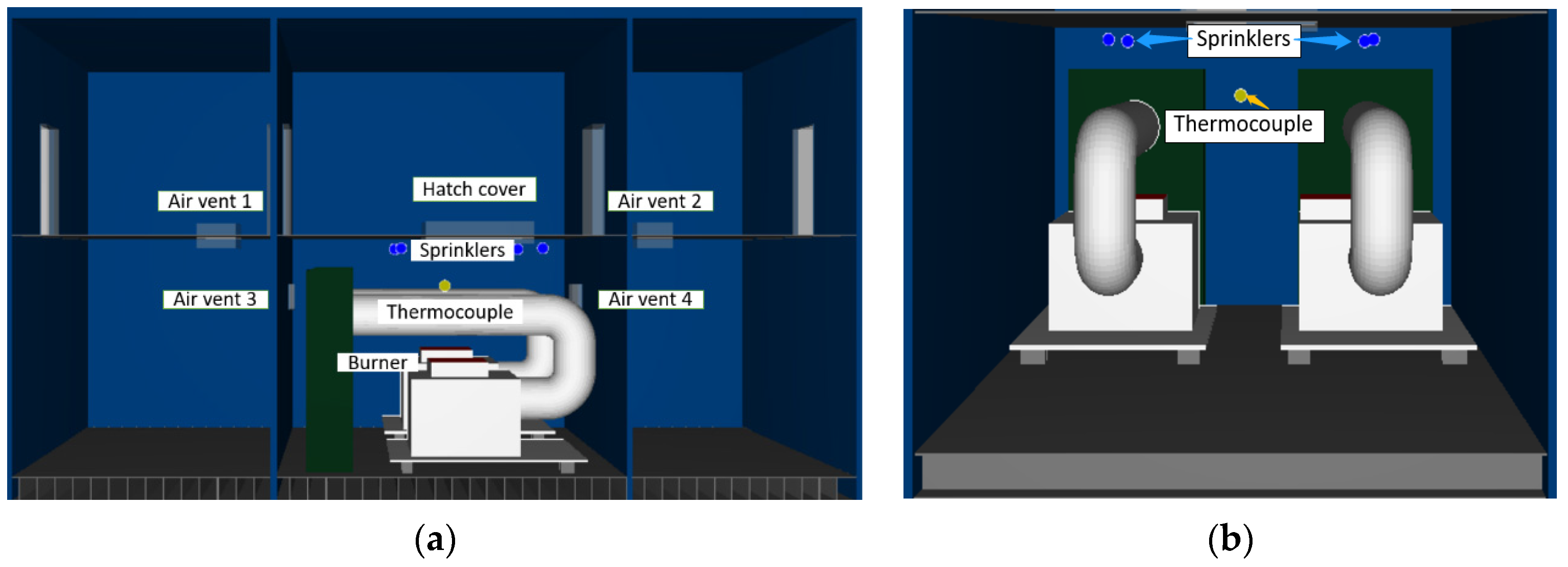
In order to accurately simulate the fire spread, FDS was used to construct the fire scene model of the three compartments with the engine room in the middle. The dimensions L × W × H of the models were 16 m × 8 m × 10 m. The design parameters of the cabin are shown in Table 1. In order to analyze the influence of ventilation conditions on the smoke spread in the engine room under fire intervention, the thermocouple was arranged at the height of Z = 4 m in the engine room, and a cap with a free switch was set on the upper part of the engine room. The longitudinal and transverse sections of the cabin are shown in Figure 1 and Figure 2. The bilge curvature was neglected and the double bottom structure was also simplified in the model.
4.2. Theoretical Settlement Model
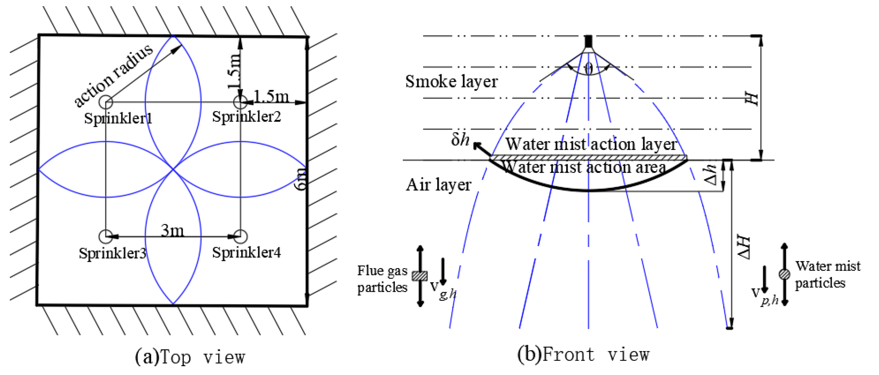
In order to study the fire spread characteristics of an engine room with different parameters of a spray system under different ventilation conditions. A comparative analysis was conducted by varying the velocity, the particle size of the water mist, and the ventilation conditions on the fire spread characteristics. The engine room of the ship falls into the definition of the serious danger level II site according to the classification of the fire hazard level of the site in accordance with the design specification of an automatic sprinkler system [27,28]. In order to ensure that the drooping spray equipment reaches the standard fire coating area, the square layout method is shown in Figure 3.
Because there is an interface between the upper layer of flue gas and the lower layer of the air thin layer (referred to as ‘thin layer’), where the flue gas temperature is the lowest and the temperature should be calculated when the temperature is more reasonable.
As shown in Figure 3b, denotes the thickness of the thin layer where the relative size of the drag force and thermal buoyancy of the flue gas in the vertical direction is analyzed; is the settlement distance of the flue gas layer; is the maximum settlement distance of the flue gas layer; is the initial thickness of the flue gas layer; is the mass of the droplets.
The average temperature in the thin layer is
where is the average flue gas temperature in the thin layer; is the upper flue gas layer temperature; is the temperature of the lower air layer; is the temperature coefficient (with a range of 0.1~0.2).
The spray envelope formed by a single ordinary water spray nozzle is a semi-spinning cone with the nozzle as the apex. Since the pressure of the water mist nozzle is large and the thickness of the smoke layer is not more than 3 m, the spray envelope is conical. The spray cross-sectional area below the nozzle is:
where is the interface spray cross-sectional area and the spray angle.
In the thin layer of volume , the spray intensity per unit volume is:
where is the density of water; the flow rate of water mist nozzle; the flow coefficient of the nozzle; the spray pressure; and the vertical component of the droplet velocity.
At higher Reynolds numbers, the Stokes viscous resistance can be neglected, and the drag force of a single droplet on the flue gas is:
where is the drag force vector of a single droplet on the flue gas; the flue gas density; the drag coefficient; the outer surface area of a single droplet; the velocity vector of droplets; and is the velocity vector of flue gas.
Before the instability phase during the intervening process, the vertical velocity can remain relatively stable and the sinking speed is slow. Therefore, the vertical velocity of the flue gas in the thin layer before the action of the water mist is neglected, and the vertical relative velocity of the droplets and the flue gas is expressed as the vertical component of the droplet velocity. The total drag force of the smoke per unit volume in the thin layer is the sum of the drag force of all droplets on the smoke:
where is the drag force of unit volume flue gas in thin layer and the number of droplets in the thin layer per unit volume.
The characteristic length in the Reynolds number corresponding to the droplets can be expressed by the size eigenvalue of the particle swarm—the Sauter mean diameter . Because it was found in the experimental test [29] that the Sauter mean diameter was very close to the median diameter of the droplets, for the convenience of theoretical analysis and numerical calculation, the characteristic diameter of the water mist particle swarm was expressed as , and the Reynolds number was:
where is the kinematic viscosity coefficient of flue gas; the velocity of the droplets; and is the density of the droplets.
The drag coefficient satisfying a certain Reynolds number range is usually treated as a constant. In fact, the drag coefficient in Equation (15) is a function of the Reynolds number and contains multiple undetermined variables. In this study, the Reynolds number range was 1~800, and the drag coefficient using the corresponding interval function is:
The kinematic viscosity coefficient v in Equation (16) is modified according to the thin layer temperature at :
where is the viscosity correction coefficient.
The shear stress applied to the droplets was very weak, and the droplets always remained spherical, so the mass of a single droplet was expressed as . In addition to the expression of the spray intensity of the water mist in the thin layer per unit volume in Equation (13), the spray intensity can also be expressed as :
The momentum (Equation (21)) of a single droplet is transformed into Equation (22). The water mist droplet diameter size is on the level of microns, which is infinitesimal and its effect can be neglected in the process of solving for the vertical velocity of droplets:
where is the initial velocity of the droplets.
Combining Equations (11)–(23), Equation (15) can be rearranged as:
The buoyancy value is related to temperature. Combined with the gas state equation, the buoyancy per unit volume of flue gas at temperature is:
where is the buoyancy force per unit volume of flue gas in the thin layer and the air density.
The ratio of drag force to buoyancy L = 1.00 was used as the theoretical threshold to determine whether the flue gas was destabilized. The relationship between the dimensionless criterion reflecting the degree of instability of the flue gas layer and the parameters of the water mist spray and the flue gas layer is:
means that the buoyancy force per unit volume of flue gas is sufficient to resist the drag force after the impact of the first jet on the flue gas layer. The viscous resistance caused by shear deformation of the flue gas can be neglected compared with the buoyancy and drag force, so the settled flue gas satisfies the momentum equation in the vertical direction:
After the first limit settlement of the flue gas, the vertical velocity of flue gas particles changes from relative rest to zero after acceleration and deceleration. Integrating of Equation (27) yields:
The above equation can be solved for the settling distance value of flue gas:
In Equation (29), and are expressed as:
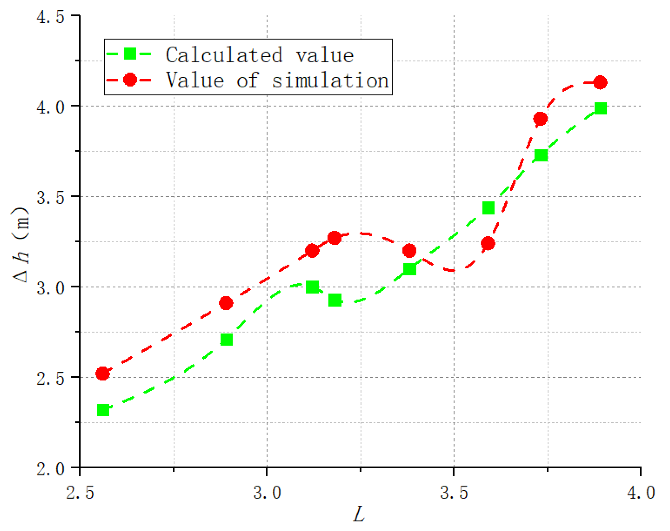
According to the settlement model of Equation (29), the theoretical smoke settlement distance of fire under various spray parameters, as shown in Table 2, was calculated and compared with the value of simulation. As shown in Figure 4, the largest difference between the numerical results and the analytical results was less than 15%, which indicates a good agreement was obtained.
5. Numerical Simulation of the Cabin Fire under Fire Intervention
5.1. Temperature Distribution of Engine Room Fire after Sealing
Water mist parameters including the spray flow, the spray speed, and the particle size of the water mist are important factors affecting the fire extinguishing effect. First, the influence of spray speed on the fire extinguishing effect was studied by keeping the particle size of the water mist at about 100 microns and varying the spray speed of the water mist under the condition of sealing the hatch cover. The parameter settings of the nozzle are listed in Table 3.
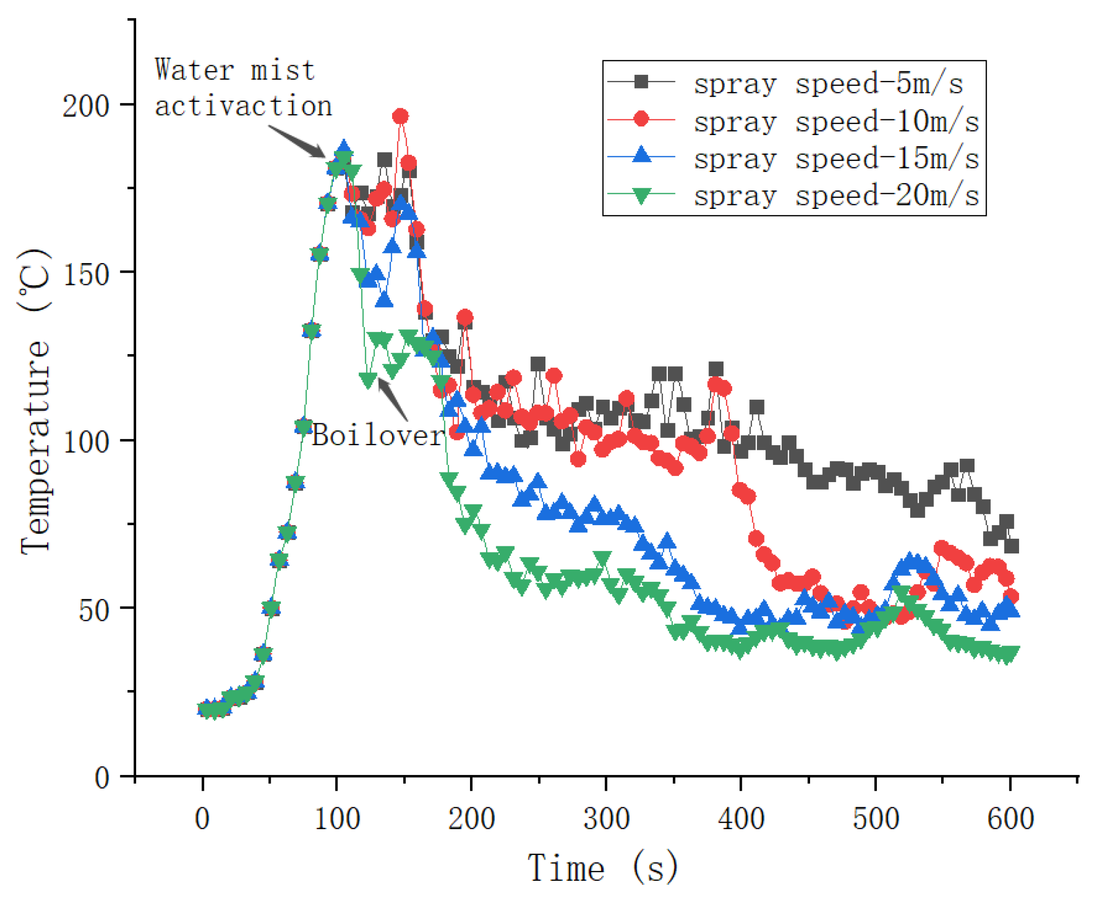
The time history of the flue gas temperature in the engine room under closed hatch cover with different spray speeds is shown in Figure 5. It can be found that the temperature decreased rapidly when the spray equipment was involved at t = 120 s, and a short boil-over phenomenon occurred in the following few seconds (about 10 s), then the smoke layer temperature increased and fluctuated again for a period of time (about 50 s). The boil-over phenomenon refers to an oil fire in which a special critical combustion condition is formed after a long combustion time, which causes a sudden change in the combustion characteristics of oil products. A large number of oil products overflow and burn outward, forming a huge column of fire, showing a very violent disastrous combustion phenomenon and a rapid rise in temperature. Subsequently, the temperature of the upper flue gas layer drops sharply, and its rate of decrease gradually slows down. Due to the timely sealing operation by the crew, the fire extinguishing effect was better when the water mist spray speed was 20 m/s and 15 m/s. However, the fire extinguishing effect in the simulation was ineffective when the water mist spray speed was 5 m/s and 10 m/s. It is worth noting that the water mist spray speed of 10 m/s was better in the later stage of fire extinguishing.
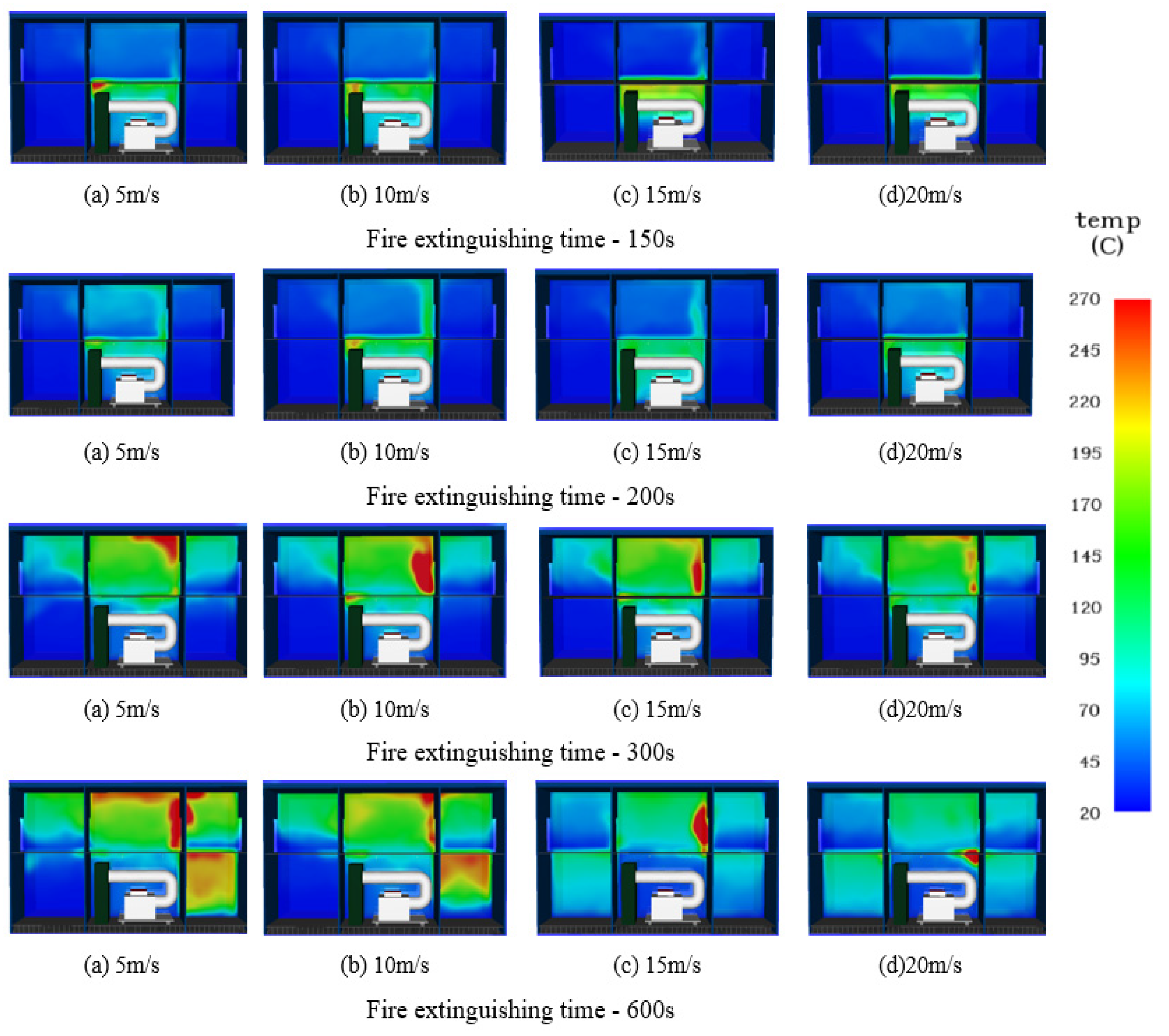
The temperature slice map of the engine room under a closed hatch cover with different spray speeds is shown in Figure 6. It can be found that the smoke generated by the oil pool fire before t = 150 s gathered in the upper part of the engine room without spreading through the vertical vent between the cabins. Due to the intervention of spraying equipment, the curtain formed by the water mist spray can effectively inhibit the spread of smoke from an oil pool fire, and the water mist with a spraying speed of 20 m/s had an obvious inhibitory effect at t = 200 s. Due to the intensified interaction between water mist and the buoyancy of thermal plume, the flue gas in the engine room first spread to the adjacent cabin through the vertical vent after a while (about 100 s), and then affected the upper cabin through the vertical vent. The water mist with the spraying speed of 20 m/s effectively inhibited the spread of the oil pool fire in the engine room at t = 600 s. Due to the ventilation conditions of the upper cabin, the temperature was maintained at about 120 °C. The speed of the water mist spray was 5 m/s and 10 m/s, which cannot effectively cover the smoke spread range. It can be concluded that when the flow rate and the particle size of the water mist remained constant, the fire suppression effect was the best with the water mist spray speed of 20 m/s. In the range of the spray speed from 5 m/s to 20 m/s, the effect of decreasing the fire temperature was more significant when the spraying speed increased faster. The reason is that the water mist with a rising spray speed has more momentum, which is conducive to overcoming the flame thermal buoyancy and penetrating the thermal plume to cool effectively, and the increase in the water mist flux per unit area is more likely to destroy the balance of oil mist combustion. However, due to violent gas exchange and air disturbances, the smoke spread through vents to various compartments, but most of them were less affected.
5.2. Effect of Particle Size of Water Mist after Cabin Sealing on Cabin Fire Temperature
The influence of the water mist particle size on fire was further analyzed. A cabin fire was simulated for the case when the cabin cover is closed after timely operation, and the optimal spray speed was maintained at 20 m/s. The parameters of the nozzles were based on the “Code for Fire Protection in Building Design” (GB50016-2014) and “Code for Design of Automatic Sprinkler System” (GB50084-2001). The influence of the water mist particle size after cabin closure on the cabin fire temperature was studied by changing the particle size of the water mist. The parameter settings of the nozzle are listed in Table 4.
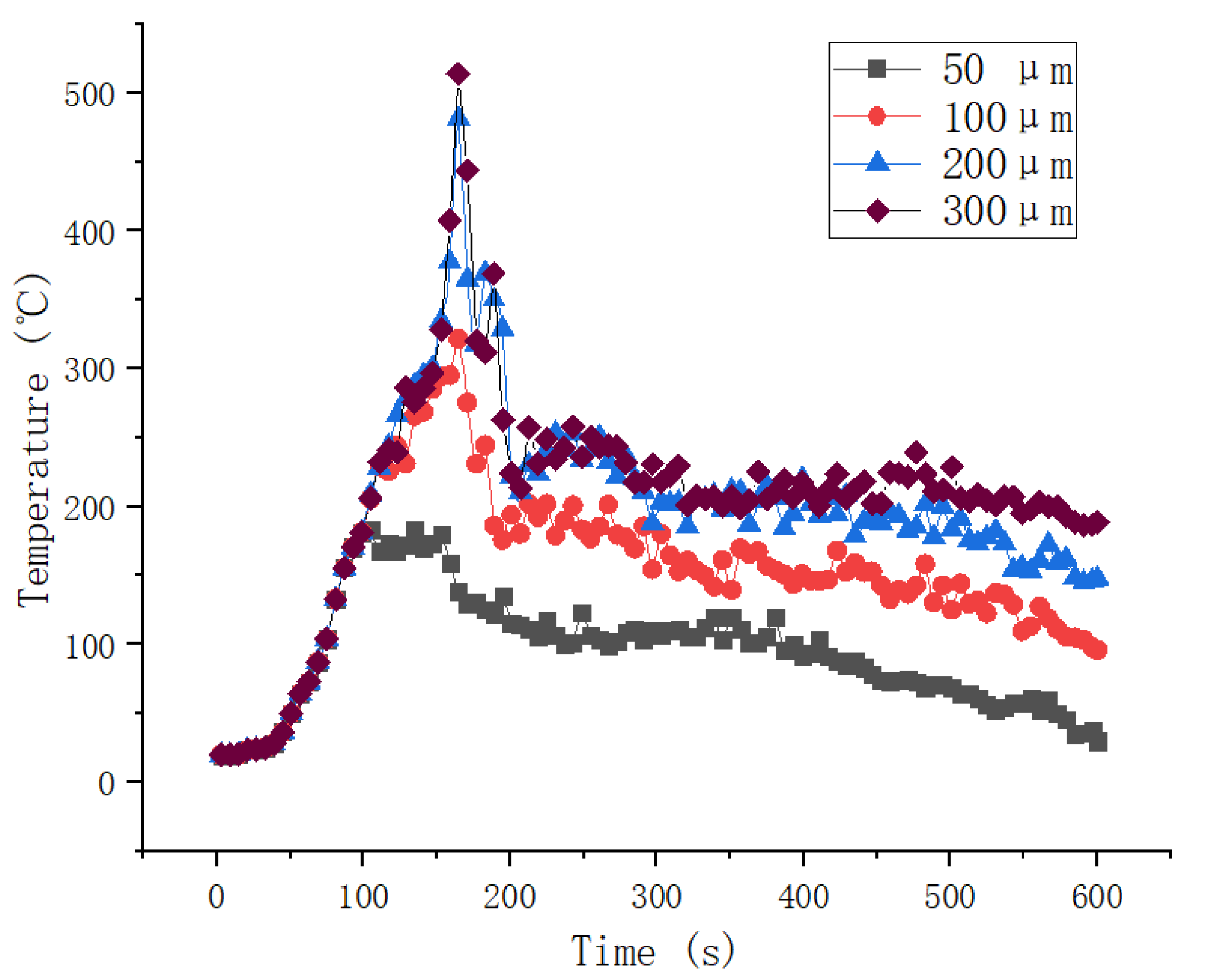
The time history of the flue gas temperature in the engine room under a closed engine room with different particle sizes of water mist is shown in Figure 7. It was found that when the spray equipment was involved in the engine room fire at t = 150 s, the temperature of the engine room decreased rapidly after the spray equipment with the involvement of a water mist particle size of 50 microns. Meanwhile, under the action of a water mist with a particle size of 50 microns, the peak temperature of the cabin temperature at t = 200 s reached about 180 °C, and then the temperature decreased slowly. The water mist could effectively inhibit the engine room oil pool fire. The fire extinguishing effect of the spray equipment with the particle sizes of 200 microns and 300 microns was the most obvious within 50 s after intervention, but the temperature slowed down after t = 200 s, and the water mist could not effectively reduce the flue gas temperature in the engine room. It can be seen that the water mist released with a particle size of over 100 microns could not directly act on the flame to extinguish the fire due to the obstacle effect. The larger particle size of the water mist quickly settled and was wasted, so it could not participate in the fire the extinguishing process, leading to the decrease in the fire extinguishing efficiency.
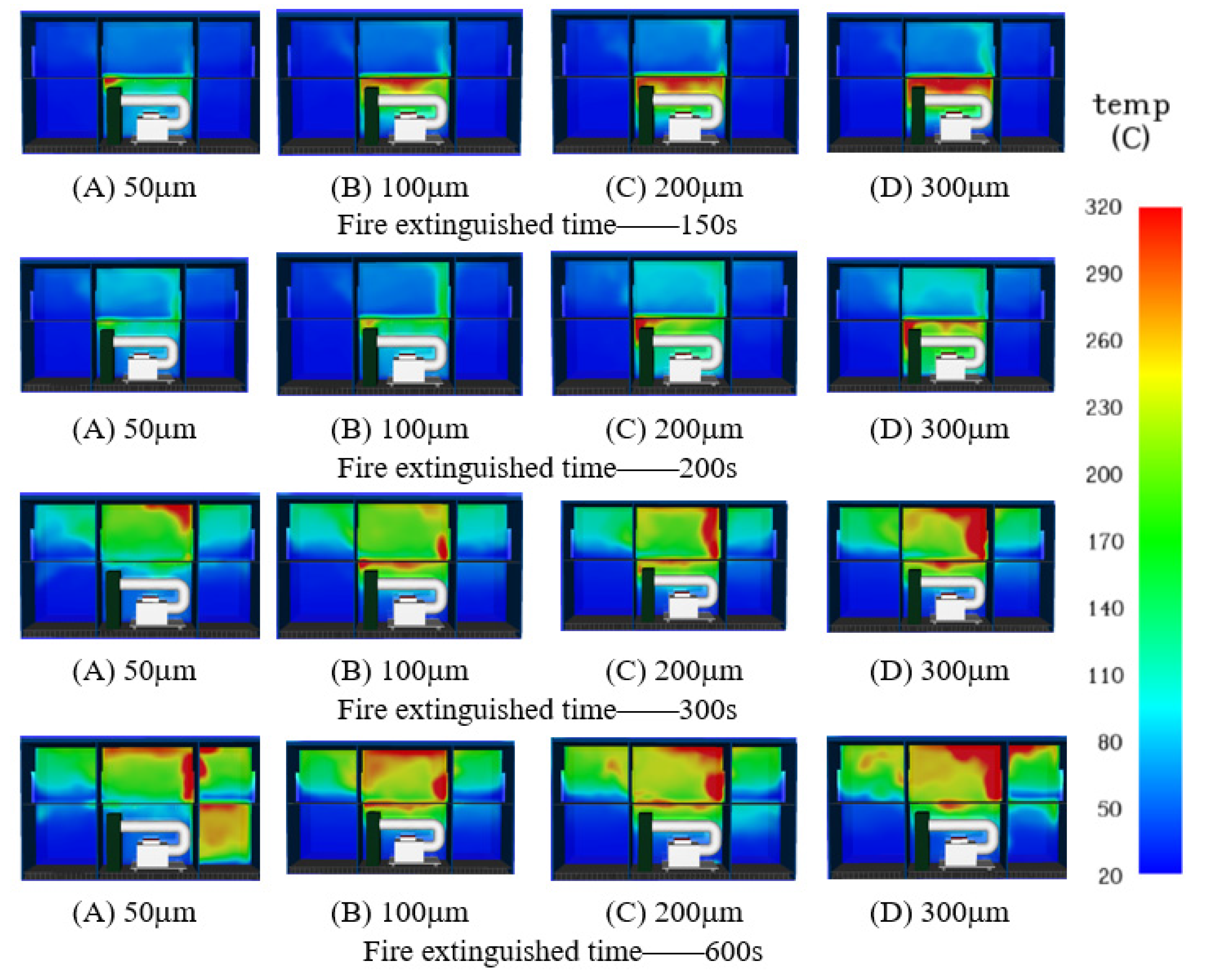
The temperature slice map of the engine room under a closed hatch cover with different particle sizes of the water mist is shown in Figure 8. It can be found that as the temperature of the flue gas layer above the engine room was effectively inhibited and increased at 150 s, the inhibition effect of a water mist particle size of 50 microns was the best. The temperature of the upper flue gas increased obviously, and the maximum temperature reached about 320 °C at 200 s. The interaction between the water mist and flue gas in the engine room intensified at 300 s, and then spread through the vent. The path of spread was from the engine room to the right cabin of the engine room and then to the upper deck cabins. The spray equipment with a water mist particle size of 50 microns had the lowest temperature in the engine room, but the right cabin of the engine room was greatly affected by smoke at t = 600 s. The influence of flame radiation was neglected when the spray equipment with a water mist particle size of 300 microns was involved, and the upper deck cabin was most affected by the smoke due to the limitation of the ventilation conditions.
It can be concluded that the spray devices maintained the same flow rate and spray speed, and then changed the particle size of the water mist. When the particle size of the water mist is reduced, it means a larger relative surface area, which will make the upward thermal buoyancy driving effect more obvious. Meanwhile, it is easier to disperse and is sucked into the surface of the spray flame and it will take more heat to achieve the cooling effect on the flame. At the same time, the smaller particle size of the water mist can effectively force the deposition of smoke particles and inhibit the harm of smoke to the ship personnel.
In order to further analyze the water mist fire extinguishing process, it is necessary to understand the interaction between smoke particles and water mist. The interaction process between smoke particles and water mist with a particle size of 50 microns is shown in Figure 9. It can be found that in the fire extinguishing process, the water mist particles have good dispersion in the cabin and are greatly affected by the thermal buoyancy of the smoke, which can effectively reduce the temperature of the smoke layer in the upper cabin. A large amount of water mist directly accumulated in the lower space of the engine room after t = 400 s, and the water mist particles overcame the thermal buoyancy effect to break through the smoke layer, thereby reducing the oxygen concentration near the flame, significantly inhibiting the spread of the oil pool fire under the engine room and achieving the effect of rapid fire suppression.
5.3. Comparative Analysis of Engine Room Fire Temperature Distribution under Different Ventilation Conditions
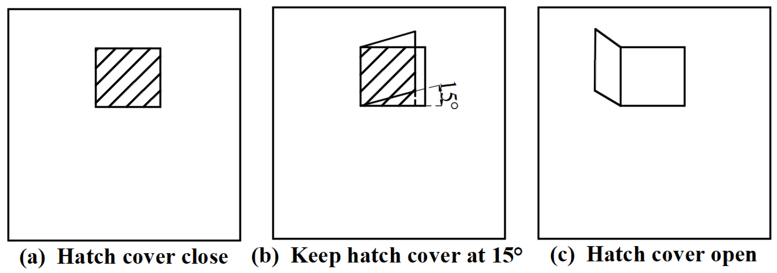
Taking into account the influence of ventilation conditions on the efficiency of water mist fire extinguishing, the ventilation conditions were set to the three most common hatch cover states: (a) the timely hatch cover sealing operation in the event of fire; (b) when a fire occurs, the cabin is not sealed in time, and the hatch cover is at 15° (the projected area is used as the area of the enclosed cabin cover); (c) the hatch cover is completely open, as shown in Figure 10. In the simulated cabin fire conditions under the action of spray, the spray scheme with a spray speed of 20 m/s and water mist particle size of 50 microns can obtain the optimal spray fire extinguishing effect. The parameter settings of the nozzle are listed in Table 5.
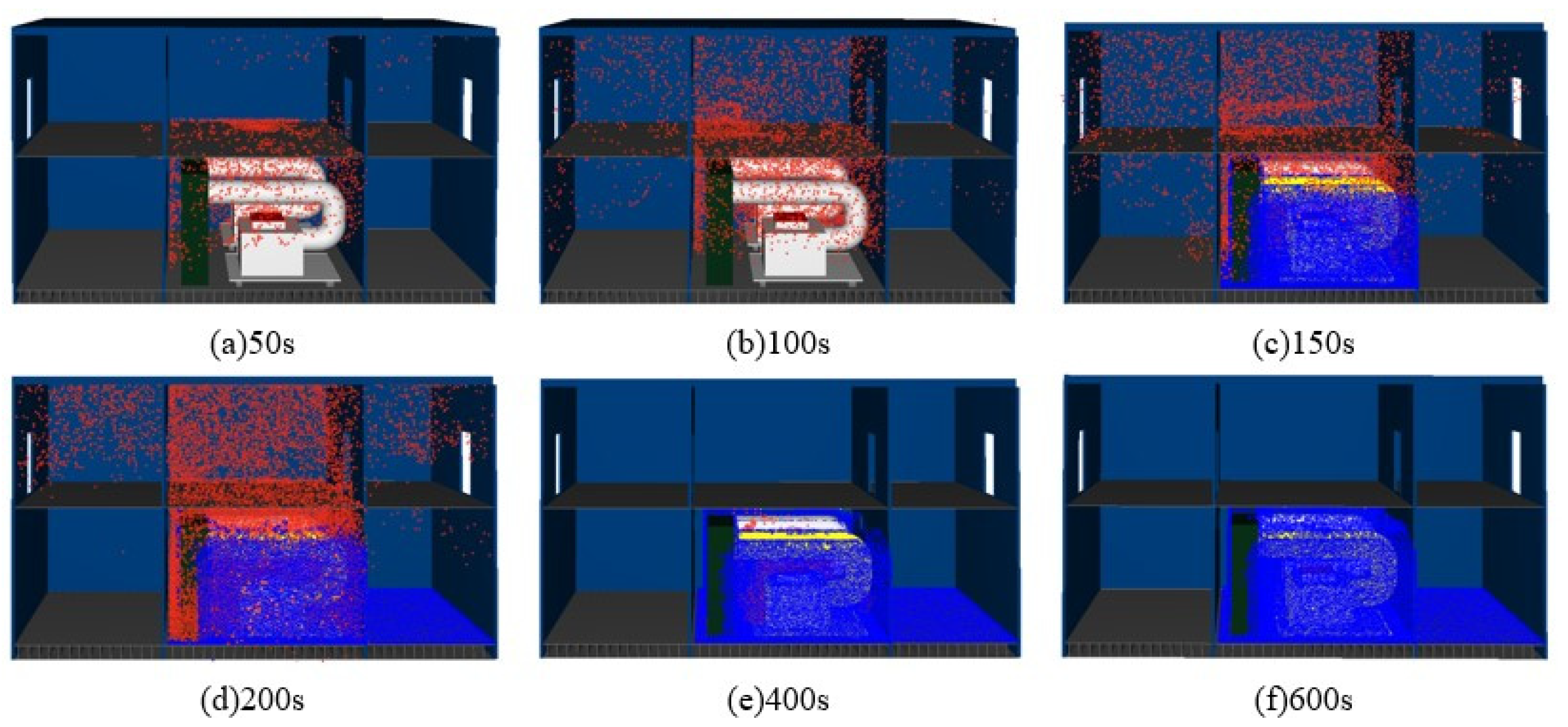
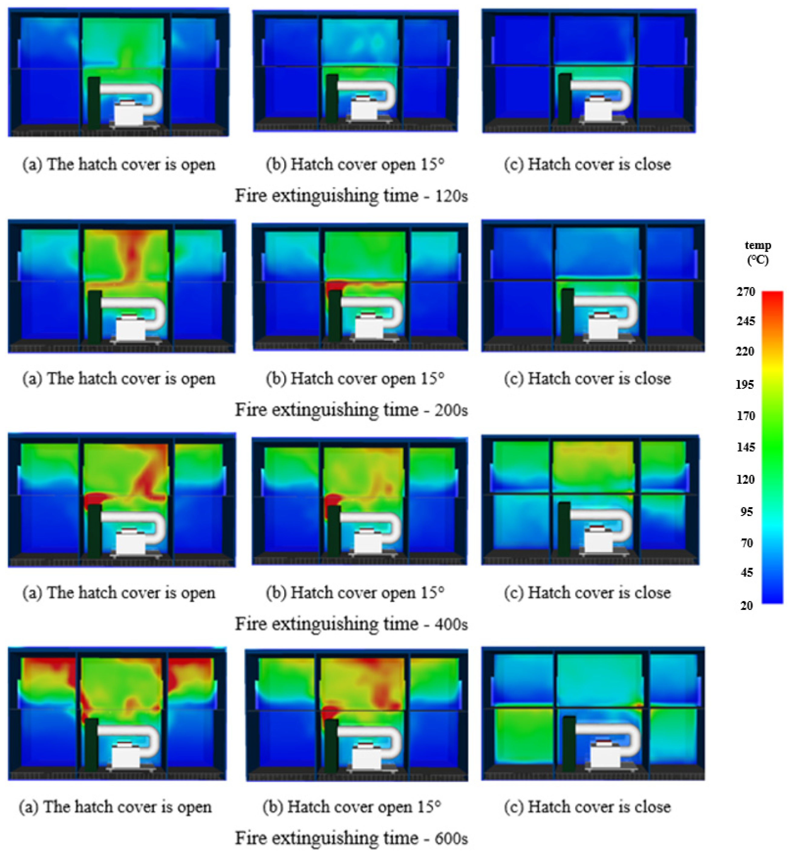
The temperature slices of the engine room under different ventilation conditions are shown in Figure 11. It can be seen that the smoke rapidly spread to the upper deck cabin when the hatch cover was completely open at t = 120 s. Subsequently, the water mist intervened in the fire process. When the hatch cover was completely open at t = 200 s, the rising process of the flame was in a whirlpool state. However, the large amount of smoke generating under the condition of cap closure was suppressed in the upper space of the cabin due to the limitation of the ventilation conditions. When the hatch cover was opened by 15°, part of the oxygen escaped to the upper cabin with the interaction of the water mist and flue gas at t = 400 s, leading to the fire spread. Due to the thermal buoyancy of the flame and air convection, the flue gas gradually diffused to other cabins at t = 600 s. The upper deck cabin under the closed hatch cover was basically filled with smoke. The main reasons for the instability of the flue gas layer are: (1) the vertical drag force exerted by the water mist with initial momentum makes the flue gas move downward and (2) the water mist absorbs the heat of the flue gas and causes the temperature of the flue gas to decrease, resulting in a decrease in the buoyancy of the flue gas.
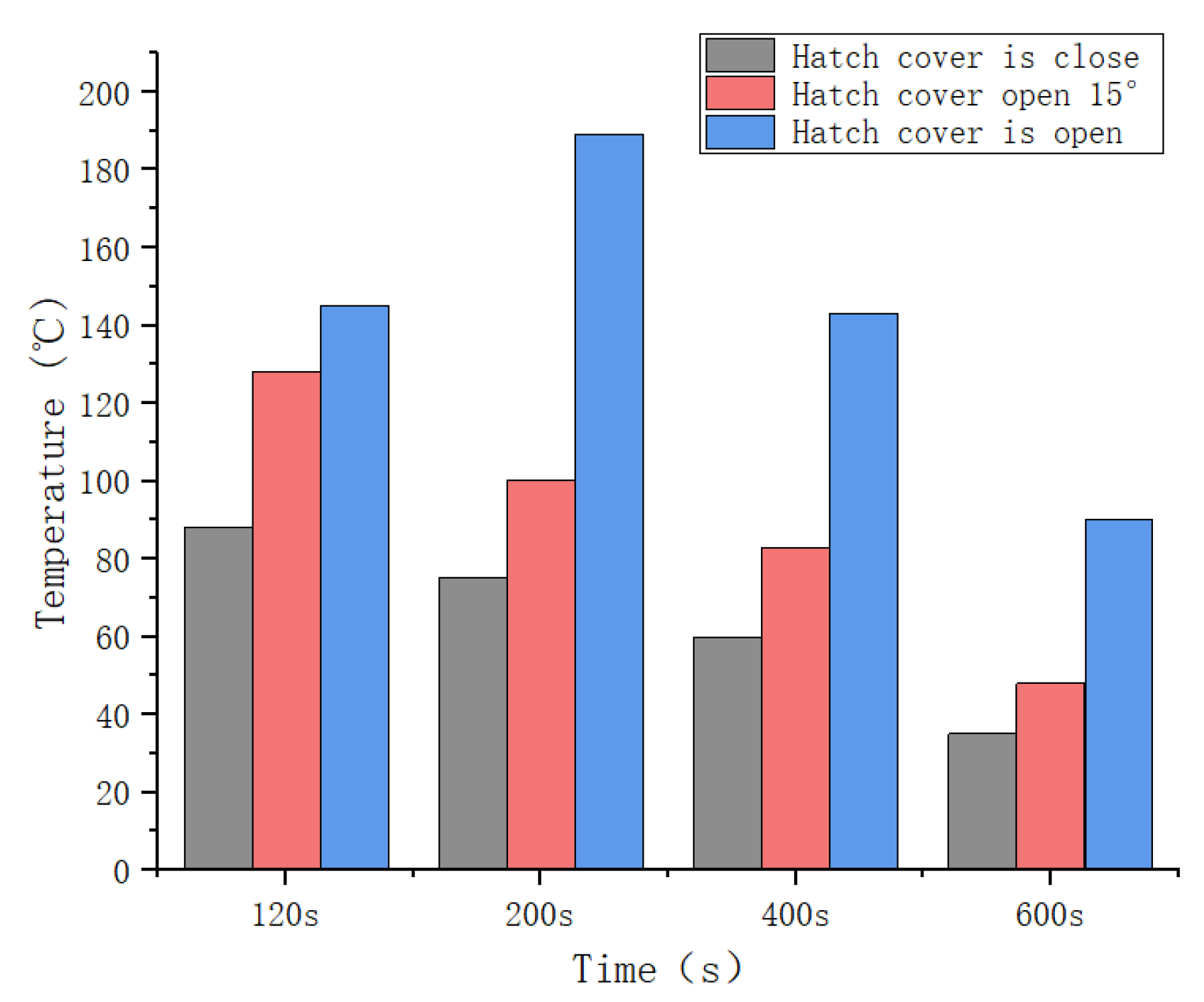
The diagram of the maximum temperature distribution of the engine room under different ventilation conditions is shown in Figure 12. It can be found that when the spray equipment is involved in a pool fire, the flashover phenomenon will occur when the ventilation area reaches a certain value, resulting in a second sharp rise in temperature. It can be concluded that the oxygen asphyxiation has an obvious effect on extinguishing oil fires, and it is necessary to seal the hatch cover first when a cabin fire occurs. The closed hatch cover forces the smoke to gather in the cabin, and the water mist can squeeze and isolate the oxygen around the flame. At the same time, the closed hatch cover separates the combustion medium, so the fire extinguishing efficiency of the spray equipment is most effective. However, due to increased gas exchange and air disturbance, the smoke spread through vents to various compartments.
6. Conclusions
In this paper, the fire extinguishing situation of the spray equipment for the rapid suppression of a pool fire in an engine room under different ventilation conditions was studied, and the influence of the particle size of the water mist was further analyzed. Based on the results and analysis, the following conclusions can be made:
- (1)
- Due to the limitation of spray flow on ships, when the spray speed under the same ventilation conditions is higher, the contact area between the water mist and thermal plume will be larger, which is more effective in the absorption of heat, and the pool fire is more likely to be extinguished. When the hatch cover is closed, it is appropriate to choose a nozzle with a flow rate of 16 L/min and spray speed of 20 m/s to extinguish the fire caused by diesel combustion in a marine engine room.
- (2)
- The oxygen suffocation caused by the rapid spraying of a large number of water mist in a closed space has a significant effect on the extinguishing of oil pool fires. When a fire occurs in the engine room, it is necessary to seal the cabin first and use a water mist under such a closed cabin space to achieve rapid fire extinguishing. However, when the hatch cover is open and the hatch cover is kept at 15°, the fire extinguishing efficiency of the water mist is greatly reduced, and sprinklers with spray speeds of 5 m/s and 10 m/s will be accompanied by a boil-over phenomenon, which will lead to a rise in the temperature and a reduction in the fire extinguishing efficiency. When the spray equipment is involved in a pool fire, flashover will occur when the ventilation area reaches a certain value, resulting in a second sharp rise in temperature.
- (3)
- Under the premise of a constant spray flow rate and spray speed, a water mist with a smaller particle size will lead to a larger relative surface area, and the upward thermal buoyancy driving effect is obvious. The water mist is easier to disperse and suck into the surface of the spray flame, thus realizing the cooling effect of the flame. When the spray speed was 15 m/s, the fire extinguishing efficiency was the highest when the particle size was 50 microns. However, when the particle size was greater than or equal to 100 microns, due to the fact that the pool fire was hidden under the oil pipeline, the fire extinguishing effect was obviously deteriorated and even reached the fire extinguishing failure state due to the decrease in the water mist flux, mainly relying on the flame entrainment and dispersion to the flame surface.
Author Contributions
Conceptualization, C.L.; Formal analysis, J.M., Z.K., S.Z. and C.L.; Funding acquisition, C.L.; Methodology, J.M., H.R., Z.K. and C.L.; Project administration, C.L.; Resources, H.R.; Supervision, H.R. and C.L.; Writing—original draft, J.M.; Writing—review & editing, H.R. All authors have read and agreed to the published version of the manuscript.
Funding
This research was supported by the National Natural Science Foundation of China (52171305) and the Science Fund Project of Heilongjiang Province (LH2020E078).
Institutional Review Board Statement
Not applicable.
Informed Consent Statement
Not applicable.
Data Availability Statement
Not applicable.
Acknowledgments
The authors thank all of the reviewers for their valuable comments.
Conflicts of Interest
The authors declare no conflict of interest.
References
- Cooper, L.Y. The interaction of an isolated sprinkler spray and a two-layer compartment fire environment. Int. J. Heat Mass Transf. 1995, 38, 679690. [Google Scholar] [CrossRef]
- Cooper, L.Y. Simulating the opening of fusible-link-actuated fire vents. Fire Saf. J. 2000, 34, 219–255. [Google Scholar] [CrossRef]
- Ingason, H. Interaction between sprinklers and fire vents. Full scale experiments. Brand. Proj. 1992, 406–902. [Google Scholar]
- McGrattan, K.B.; Hamins, A.; Stroup, D.W. Sprinkler, Smoke & Heat Vent, Draft Curtain Interaction: Large Scale Experiments and Model Development; NIST: Gaithersburg, MD, USA, 1998; p. 101.
- Braun, E.; Lowe, D.L.; Jones, W.W.; Tatem, P.; Carey, R.; Bailey, J. Comparison of full scale fire tests and a computer fire model of several smoke ejection experiments. NASA STI/Recon Tech. Rep. N 1992, 93, 23280. [Google Scholar]
- Raj, V.C.; Prabhu, S.V. Measurement of geometric and radiative properties of heptane pool fires. Fire Saf. J. 2018, 96, 13–26. [Google Scholar] [CrossRef]
- Tao, C.; Liu, Y.; Tang, F.; Wang, Q. An experimental investigation of the flame height and air entrainment of ring pool fire. Fuel 2018, 216, 734–737. [Google Scholar] [CrossRef]
- Leite, R.M.; Centeno, F.R. Effect of tank diameter on thermal behavior of gasoline and diesel storage tanks fires. J. Hazard. Mater. 2018, 342, 544–552. [Google Scholar] [CrossRef]
- Utiskul, Y.; Quintiere, J.G.; Rangwala, A.S.; Ringwelski, B.A.; Wakatsuki, K.; Naruse, T. Compartment fire phenomena under limited ventilation. Fire Saf. J. 2005, 40, 367–390. [Google Scholar] [CrossRef]
- Pearson, A.; Most, J.M.; Drysdale, D. Behaviour of a confined fire located in an unventilated zone. Proc. Combust. Inst. 2007, 31, 2529–2536. [Google Scholar] [CrossRef]
- Yoshida, K. Full-scale model tests of smoke movement in ship passenger accommodations (first report). ASTM Spec. Tech. Publ. 1998, 1336, 163–171. [Google Scholar]
- White, D.A.; Beyler, C.L.; Scheffey, J.L.; Williams, F.W. Modeling the impact of post-flashover shipboard fires on adjacent spaces. J. Fire Prot. Eng. 1999, 10, 2–18. [Google Scholar] [CrossRef]
- Andersson, C.; Säterborn, D. Smoke Control Systems Aboard—A Risk Analysis of Smoke Control Systems in Accommodation Spaces on Passenger Ships. LUTVDG/TVBB—5093—SE; Lund University: Lund, Sweden, 2002. [Google Scholar]
- Sprague, C.M.; Richards, R.C.; Blanchard, M.A. A methodology for evaluation of ship fire safety. Nav. Eng. J. 1992, 104, 104–113. [Google Scholar] [CrossRef]
- Ndubizu, C.C.; Brown, R.A.; Tatem, P.A.; Williams, F.W. Fire hazard assessment in submarine plastic waste stowage compartments. SAMPE J. 2001, 37, 42–58. [Google Scholar]
- Rockett, J.A. Fire Growth in Combat Ships (No. NBSIR—86/3451); US Department of Commerce, National Bureau of Standards: Gaithersburg, MD, USA, 1986.
- Lee, D.H.; Paik, J.K.; Seo, J.K. Efficient water deluge nozzles arrangement on offshore installations for the suppression of pool fires. Ocean. Eng. 2018, 167, 293–309. [Google Scholar] [CrossRef]
- Shrigondekar, H.; Chowdhury, A.; Prabhu, S.V. Characterization of a simplex water mist nozzle and its performance in extinguishing liquid pool fire. Exp. Therm. Fluid Sci. 2018, 93, 441–455. [Google Scholar] [CrossRef]
- Jenft, A.; Collin, A.; Boulet, P.; Pianet, G.; Breton, A.; Muller, A. Experimental and numerical study of pool fire suppression using water mist. Fire Saf. J. 2014, 67, 1–12. [Google Scholar] [CrossRef]
- Lee, J. Numerical analysis of how ventilation conditions impact compartment fire suppression by water mist. Ann. Nucl. Energy 2020, 136, 107021. [Google Scholar] [CrossRef]
- Liang, T.; Liu, M.; Liu, Z.; Zhong, W.; Xiao, X.; Lo, S. A study of the probability distribution of pool fire extinguishing times using water mist. Process Saf. Environ. Prot. 2015, 93, 240–248. [Google Scholar] [CrossRef]
- Wang, L.; Su, S.C.; Wei, C.Y.; Chen, C.Y. A study on the flow field and the structure of fire plumes in the coupling process of the water mist and the jet fire of diesel fuel. Procedia Eng. 2018, 211, 736–746. [Google Scholar] [CrossRef]
- Tianshui, L.; Mengjie, L.; Xinli, W.; Wei, Z. An experimental study on the interaction of water mist with vertical/horizontal spray flame. Procedia Eng. 2014, 84, 543–552. [Google Scholar] [CrossRef]
- Yang, P.; Liu, T.; Qin, X. Experimental and numerical study on water mist suppression system on room fire. Build. Environ. 2010, 45, 2309–2316. [Google Scholar] [CrossRef]
- Heskestad, G.; Bill, R.G., Jr. Quantification of thermal responsiveness of automatic sprinklers including conduction effects. Fire Saf. J. 1988, 14, 113–125. [Google Scholar] [CrossRef]
- McGrattan, K.B.; Forney, G.P.; Floyd, J.; Hostikka, S.; Prasad, K. Fire Dynamics Simulator (Version 5): User’s Guide; US Department of Commerce, Technology Administration, National Institute of Standards and Technology: Gaithersburg, MD, USA, 2005; pp. 5–15.
- Yu, H.Z. Investigation of spray patterns of selected sprinklers with the FMRC drop size measuring system. In First International Symposium on Fire and Safety Science, 1985; Grant University of California: Berkeley, CA, USA, 1986; pp. 1165–1176. [Google Scholar]
- Ministry of Public Security, PRC. Code of Design for Sprinkler Systems GB 50084-2001; China Planning Press: Beijing, China, 2001. [Google Scholar]
- Wang, Z.; Wang, X.; Huang, Y.; Tao, C.; Zhang, H. Experimental study on fire smoke control using water mist curtain in channel. J. Hazard. Mater. 2018, 342, 231–241. [Google Scholar] [CrossRef] [PubMed]
Figure 1.
The arrangement diagram of the engine room cabin.

Figure 2.
Engine room model equipped with the fire extinguishing equipment of water mist. (a) Longitudinal section. (b) Transverse section. (blue circle: Sprinklers, yellow circle: Thermocouple).
Figure 2.
Engine room model equipped with the fire extinguishing equipment of water mist. (a) Longitudinal section. (b) Transverse section. (blue circle: Sprinklers, yellow circle: Thermocouple).

Figure 3.
Schematic diagram of the water mist interacting with the smoke layer. (blue lines are fine water mist paths).
Figure 3.
Schematic diagram of the water mist interacting with the smoke layer. (blue lines are fine water mist paths).

Figure 4.
Comparison of the calculated values of the subsidence model and simulated values.

Figure 5.
Time histories of the flue gas temperature in the engine room under a closed hatch cover with different spray speeds.
Figure 5.
Time histories of the flue gas temperature in the engine room under a closed hatch cover with different spray speeds.

Figure 6.
Temperature slice map of the engine room under a closed hatch cover with different spray speeds (color bar unit: °C).
Figure 6.
Temperature slice map of the engine room under a closed hatch cover with different spray speeds (color bar unit: °C).

Figure 7.
Time history of the flue gas temperature in the engine room under a closed engine room with different particle sizes of the water mist.
Figure 7.
Time history of the flue gas temperature in the engine room under a closed engine room with different particle sizes of the water mist.

Figure 8.
Temperature slice map of the engine room under a closed hatch cover with different particle sizes of the water mist (color bar unit: °C).
Figure 8.
Temperature slice map of the engine room under a closed hatch cover with different particle sizes of the water mist (color bar unit: °C).

Figure 9.
The interaction process of the flue gas particles and water mist particle size of 50 microns.
Figure 9.
The interaction process of the flue gas particles and water mist particle size of 50 microns.

Figure 10.
Schematic diagram of the hatch cover.

Figure 11.
Temperature section under different ventilation conditions.

Figure 12.
The maximum temperature of the engine room under different ventilation conditions.


Table 1.
Parameters of the cabin used in the analysis.
| The Parameter Name | Numerical Value |
|---|---|
| Deck materials | Q235 (8 mm) |
| The wall material | Q235 (8 mm) |
| Atmospheric pressure | 101,325 Pa (1 atm) |
| The outside temperature | 20 °C |
| Humidity | 50% |
| Lower limit of oxygen mass fraction | 15% |
Table 2.
Parameters of the case.
| = 2 MPa |
| = 2.5 MPa |
| = 3 MPa |
| = 3.5 MPa |
| = 3.5 MPa |
| = 3.5 MPa |
| = 3.5 MPa |
| = 3.5 MPa |
Table 3.
The parameters of the nozzles used in the analysis.
| Parameter | Value |
|---|---|
| Spray flow | 16 L/min |
| working pressure | 2 MPa |
| Number of droplets per second | 5000 |
| Particle size of fine water mist | 100 microns |
| Activation temperature of nozzle | 74 °C |
| Minimum spray angle | 0° |
| Maximum spray angle | 60° |
Table 4.
The parameters of the nozzles used in the analysis.
| Parameter | Value |
|---|---|
| Spray flow | 16 L/min |
| Working pressure | 2 MPa |
| Number of droplets per second | 5000 |
| Spray speed | 20 m/s |
| Activation temperature of nozzle | 74 °C |
| Minimum spray angle | 0° |
| Maximum spray angle | 60° |
Table 5.
Parameters of the nozzles used in the analysis.
| Parameter | Value |
|---|---|
| Spray flow | 16 L/min |
| Working pressure | 2 MPa |
| Number of droplets per second | 5000 |
| Spray speed | 20 m/s |
| Activation temperature of nozzle | 74 °C |
| Minimum spray angle | 0° |
| Maximum spray angle | 60° |
| Particle size of fine water mist | 50 microns |
Disclaimer/Publisher’s Note: The statements, opinions and data contained in all publications are solely those of the individual author(s) and contributor(s) and not of MDPI and/or the editor(s). MDPI and/or the editor(s) disclaim responsibility for any injury to people or property resulting from any ideas, methods, instructions or products referred to in the content. |
© 2023 by the authors. Licensee MDPI, Basel, Switzerland. This article is an open access article distributed under the terms and conditions of the Creative Commons Attribution (CC BY) license (https://creativecommons.org/licenses/by/4.0/).
Share and Cite
MDPI and ACS Style
Li, C.; Mao, J.; Kang, Z.; Zhao, S.; Ren, H. Influence of Firefighting Intervention on Fire Spread Characteristics in Ship Engine Room. J. Mar. Sci. Eng. 2023, 11, 877. https://doi.org/10.3390/jmse11040877
AMA Style
Li C, Mao J, Kang Z, Zhao S, Ren H. Influence of Firefighting Intervention on Fire Spread Characteristics in Ship Engine Room. Journal of Marine Science and Engineering. 2023; 11(4):877. https://doi.org/10.3390/jmse11040877
Chicago/Turabian StyleLi, Chenfeng, Jiayin Mao, Zixiong Kang, Shengzhu Zhao, and Huilong Ren. 2023. "Influence of Firefighting Intervention on Fire Spread Characteristics in Ship Engine Room" Journal of Marine Science and Engineering 11, no. 4: 877. https://doi.org/10.3390/jmse11040877
Note that from the first issue of 2016, this journal uses article numbers instead of page numbers. See further details here.