
A Manta Ray Robot with Soft Material Based Flapping Wing
by
 , , , ,
Qimeng Liu
1,2 ,
,
Hao Chen
1,2,
Zhenhua Wang
1,2,
Qu He
1,2,
Linke Chen
2,
Weikun Li
2,
Ruipeng Li
2 and
Weicheng Cui
2,* 1
Zhejiang University-Westlake University Joint Training, Zhejiang University, Hangzhou 310024, China
2
Key Laboratory of Coastal Environment and Resources of Zhejiang Province (KLaCER), School of Engineering, Westlake University, Hangzhou 310024, China
*
Author to whom correspondence should be addressed.
J. Mar. Sci. Eng. 2022, 10(7), 962; https://doi.org/10.3390/jmse10070962
Submission received: 19 June 2022
/
Revised: 4 July 2022
/
Accepted: 12 July 2022
/
Published: 14 July 2022
(This article belongs to the Special Issue Frontiers in Deep-Sea Equipment and Technology)
Abstract
:Recent research on robotic fish mainly focused on the bionic structure design and realizing the movement with smart materials. Although many robotic fish have been proposed, most of these works were oriented toward shallow water environments and are mostly built with purely rigid structures, limiting the mobility and practical usability of robotic fish. Inspired by the stability of the real manta ray, a manta ray robot design is proposed with soft material made flapping wing based on an open-source ROV (Remotely Operated Vehicle). The flapping wing structure with three different materials mimics the wide pectoral fins of real manta rays, which have bones, muscles, and skin. Furthermore, its modular design makes it easy to install and disassemble. The kinematic and hydrodynamic analysis of the manta ray robot are simulated in this paper. The actual manta ray robot is fabricated and several sets of test are performed in the pool. The robot can swim forward continually and stably with a simple rolling and pitching pattern.
1. Introduction
The ocean has lots of energy, biological, and metal resources. It is the most realistic and potential space for human beings’ sustainable development [1]. Traditional underwater vehicles are relatively large, limiting their flexibility in underwater operations and generating significant noise when navigating and operating in the ocean, often negatively affecting the marine environment. In addition, the low level of intelligence, high operating costs, and maintenance costs also greatly shackled the large-scale and efficient application and implementation of underwater vehicles in ocean engineering. The rapid development of ocean engineering has led to an urgent need for new tools and equipment, especially underwater bionic robots for marine tasks. Underwater robots help humans understand, develop, and protect the ocean [2]. Underwater robots designed for tasks in areas and depths that are difficult to reach with standard diving technology will bring ocean development into a whole new era [3]. However, the typical underwater robots can rarely survive under certain circumstances [4].
As a result of millions of years of evolution, fish can perform very efficient and fast swimming movements. In comparing the performance of conventional underwater vehicles with the performance of various fish in the ocean, there is a big gap in their navigation ability, rapidity, maneuverability, propulsion efficiency, and control of vibration noise. Fish can swim at high speeds and turn with high maneuverability compared with conventional underwater vehicles. Furthermore, the wake structure of fish is difficult to differentiate from the environment, while conventional underwater vehicles have regular patterns and are easily detected [5]. To improve the performance of underwater vehicles, it is necessary to study the characteristics of fish systematically, fully understand the unique advantages and motion mechanisms of fish, selectively apply them to the design of submersibles, and develop the intelligent bionic machine-fish underwater robot, which is an inevitable trend in the development of underwater vehicle technology.
After years of observation and study, fish propulsion can be categorized into two types: Body and/or Caudal Fin propulsion (BCF) and Median and/or Paired Fin propulsion (MPF) [6,7,8]. The BCF propulsion mode has been studied for years since it has excellent acceleration and high-speed performance. The MPF propulsion mode is good at mobility, stability, and concealment. According to different circumstances, different fish should adopt different propulsion modes [6]. For example, the BCF propulsion mode is more suitable for high-speed cruising scenes, while the MPF propulsion mode is good at gliding and long-distance movement. The Manta ray is a representative MPF propulsion mode fish, and its giant pectoral fins are of interest to many researchers. Through physical observation and anatomical experiments, the structure of the pectoral fin has been examined that the stiffness is variable in different parts [9]. Both oscillation and undulatory swimming patterns have been investigated. Digital particle image velocity (DPIV) is applied to study the relationship between efficiency and wake structure of a batoid-inspired oscillating fin [10]. This work reveals that the bifurcation distance decreases with increasing Strouhal number and wavelength, and it is shown to obey a simple scaling law. The boundary element method(BEM) is used to analyze the hydrodynamic performance of the flapping wing [11]. Their work indicates that the distal part of the fin generates the most thrust force. Parameters of the pectoral fin, such as amplitude, frequency, initial angle, and phase difference, are closely related to swimming performance.
Much effort has been devoted to designing and manufacturing manta ray type robotic fish. For the MPF propulsion mode robotic fish, studying the bionic pectoral fin is the most significant part. The first manta ray robot has a design where a leading-edge fin rib caused passive undulation to a membrane supported by a second rib running parallel to the body [12]. The body is a rigid unit with fixed control surfaces as horizontal and vertical tails. This robot is then upgraded into the Robo-Ray III, where the fixed control surfaces are replaced with functioning ones that increase stability and depth control [13]. A pneumatic fin flexion ray is designed, and it is control-tethered to supply power to actuators that pull on the cables that cause the rigid skeleton to morph for an upstroke. The skeleton is encased in a mimetic body resembling the Manta Ray [14]. The pectoral fin usually has fixed stiffness for conventional robotic fish since the typical propeller is rigid. Researchers from Harvard University found that a dead fish could be propelled upstream when its flexible body resonated with oncoming vortices formed in the wake of a bluff cylinder, despite being well outside the suction region of the cylinder [15,16]. This reveals that the soft material can be used to produce the fin structure, and it has better hydrodynamic performance than the rigid one. Recently, more and more smart materials are used as the actuator of the bionic robot fish, such as shape memory alloy (SMA), ion-exchange polymer-metal composite (IPMC), and dielectric elastomer (DE) [8,17,18,19]. These designs are still prototypes in the laboratory and have not been applied in practical use. To date, the electric motor is the best choice for the actuator of the bionic robot fish since it has the highest efficiency. An improved crank rocker mechanism was developed for a bionic robotic fish [20]. It has the advantage of changing pitch maneuverability by adjusting the sweep angle of the pectoral fin, and a free-swimming experiment is conducted. A bionic flapping pectoral fin with adjustable spatial deformation was designed and tested in a towing tank for thrust and lift [21].
There are various manta ray robots, and many new attempts have been made, leading to even more ocean engineering progress. However, the following problems still exist.
- Previous manta ray robots usually used rigid or sing material to fabricate the pectoral fin, which does not have good hydrodynamic properties.
- The pectoral fin structure is complicated and not easy to realize on large-scale underwater vehicles.
- Most robotic fishes do not have a modular design, which is very difficult to expand other features, such as depth sensor, camera, etc.
Based on the previous work and the discussion mentioned above, the main contributions of this paper are summarized as follows.
- A manta ray robot with a soft material-based flapping wing is designed and manufactured. The soft material is carefully selected and tested. The flapping wing kinematic is analyzed. Furthermore, the hydrodynamic performance is calculated and compared with the traditional ROV.
- The manta ray robot can swim forward continuously and steadily with simple rolling and pitching motion. Furthermore, the influence of frequency and rotation angle of the flapping and pitching angle on the swimming speed are investigated.
- The manta ray robot is based on an open-source ROV structure with many expandable interfaces and devices.
The rest of this article is organized as follows. Section 2 describes the mechanical structure of the flapping wing and the main body. Section 3 gives the kinematic and hydrodynamic analysis of the manta ray robot and comparisons with open-source ROV. Section 4 presents the experiment setting and the result analysis. Finally, conclusions and future work are discussed in Section 5.
2. Mechanical Structure
2.1. Flapping Wing Design
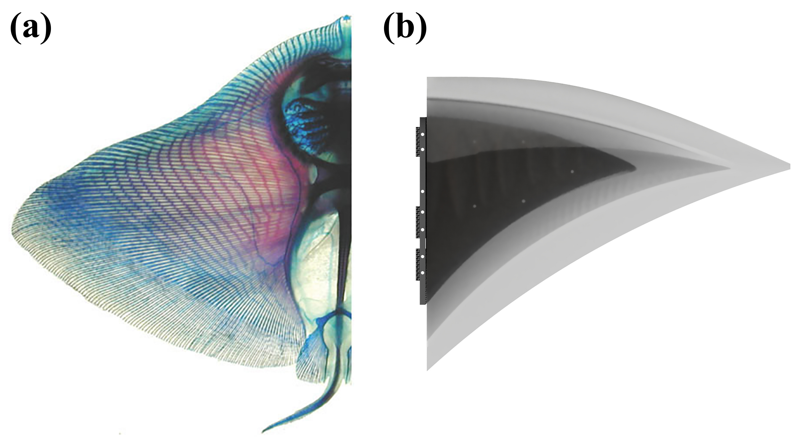
The Manta Ray’s pectoral fin comprises cartilage, muscle, and epidermis, as shown in Figure 1a. This kind of structure is similar to the flapping wings of birds, while the manta ray has flexible covered skin. The real manta ray has numerous support structures inside the pectoral fin, and these structures could be controlled separately, making the manta ray swim like a dancer in water. For many manta ray robots, motors and rigid structures are commonly used. These structures could hardly mimic the deformation of the manta ray’s pectoral fins.
As observed from the previous study, the motion of the manta ray can be seen as the transmission of the wave, and the movement is simplified as a sine curve [22]. Most of the previous research focuses on the degree of freedom design or smart material on the flapping wing, which brings many difficulties to the practical applications. This paper proposes a novel approach to achieve the advantages of the manta ray and ROV/AUV(Autonomous Underwater Vehicle). The structure of the flapping wing is shown in Figure 1b and Figure 2. Furthermore, the flapping wing is given two degrees of freedom to generate the corresponding servos’ pitching and rolling motions.
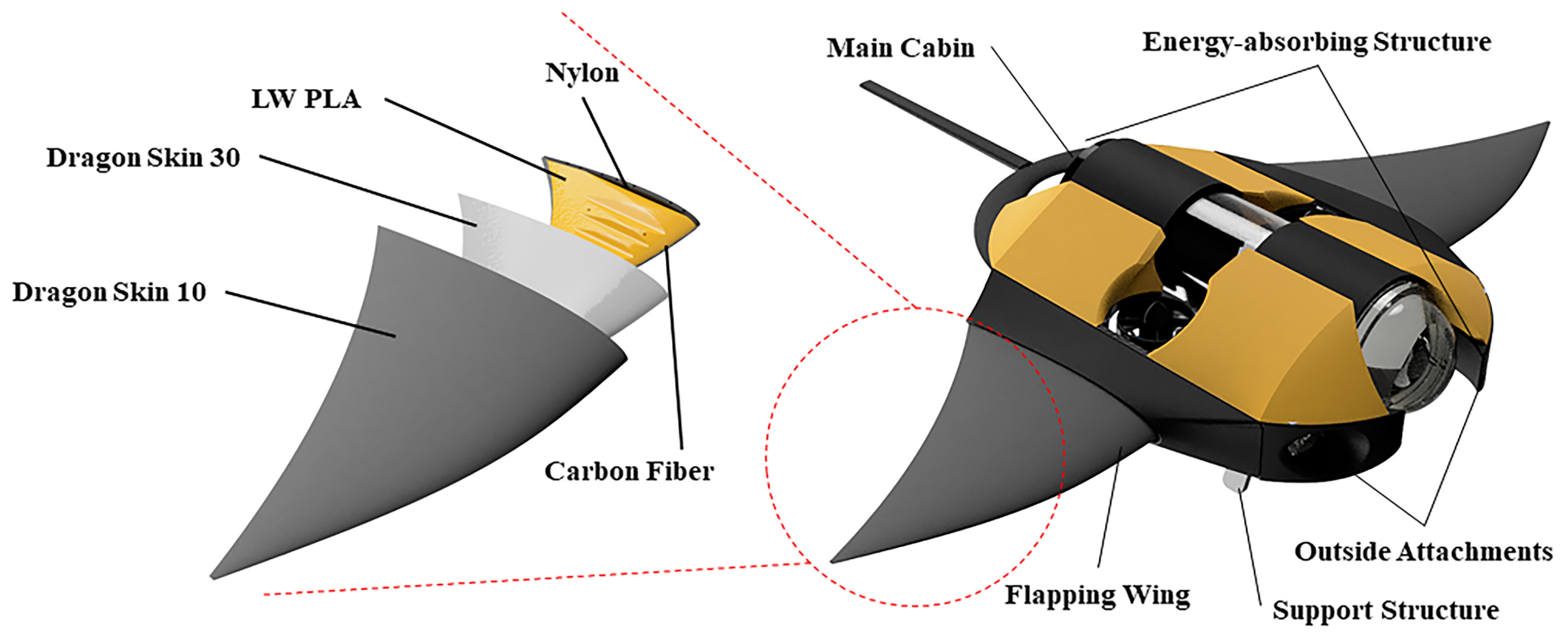
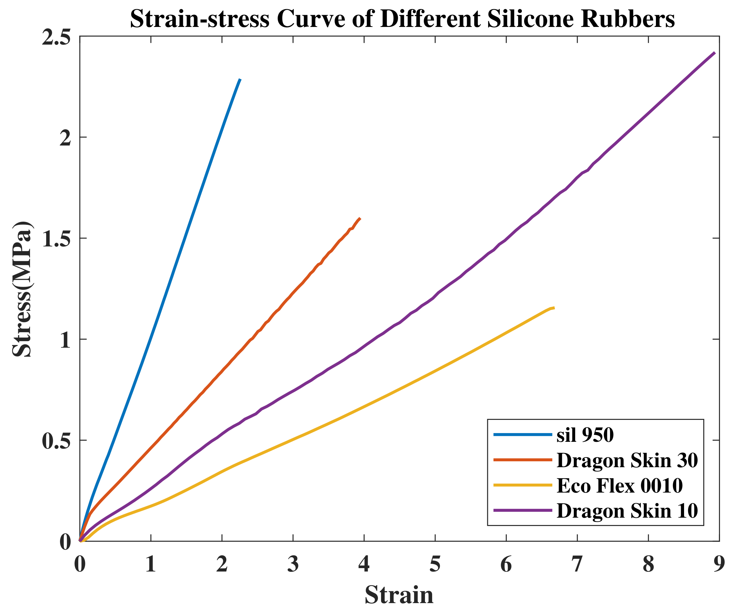
The pectoral fin of the real manta ray has two kinds of deformations, active and passive. The active deformation comes from the manta ray itself, which could drive the pectoral fin to generate specific movement, while the passive deformation comes from the fluid–structure interaction, which could better drain the vortex. A flapping wing with a variable stiffness structure is proposed to combine active and passive deformations. The flapping wing has three layers with three different materials, which have variable stiffness. The materials used include LW PLA(Light Weight Polylactic Acid) and silicone rubbers. Considering the mechanical qualities of material and simplicity of manufacture, four different silicone rubbers are chosen and shown in Figure 3. Dragon Skin® 30 and Dragon Skin® 10 are chosen because these two kinds of materials have better elasticity modulus. 3D printed LW PLA material as the shell is applied in the inside layer since it could adjust the buoyancy of the flapping wing with a specific strength. Moreover, carbon fiber is used as the support structure. Dragon Skin® 30 is used in the middle layer. Dragon Skin® 10 is used in the outside layer.
2.2. Main Body Design
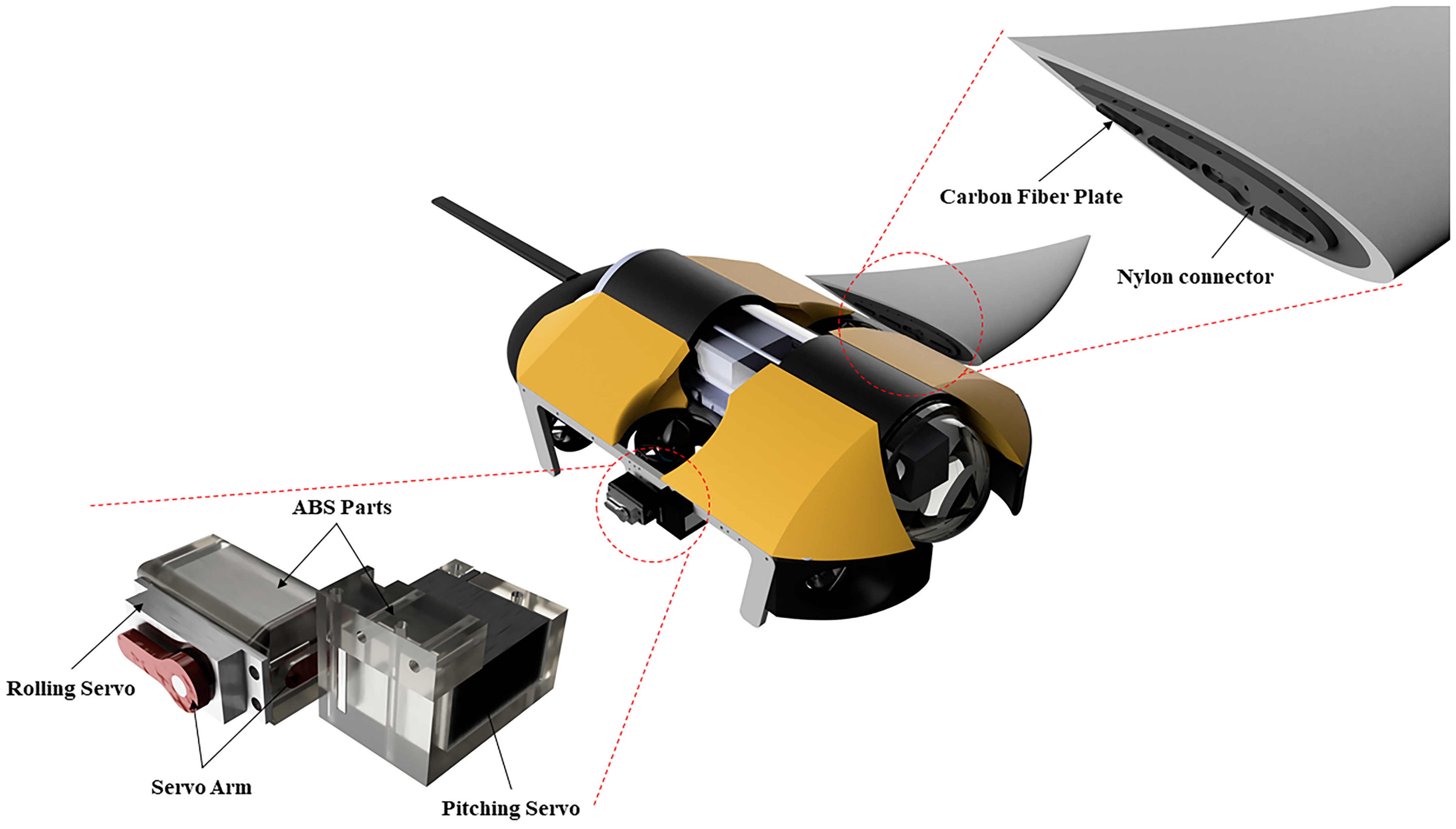
All manta rays have a distinctive triangular body shape in their physical structure. The outline of the manta ray robot comes from observing the appearance of the manta ray. The main body includes the main cabin, support structure, energy-absorbing structure, flapping wing, and outside attachments, as shown in Figure 4. Since the main cabin is the critical component of the manta ray robot, a open-source ROV, Blue ROV, is studied to improve the hardware connection. Inside are the control unit, power unit, communication unit, camera unit, and sensor unit. The support structure has four-point and four-line support, which stabilizes the overall manta ray robot.
Compared with the traditional ROV, this kind of design could adjust the landing attitude in a better way. The manta ray has two fins on their heads known as cephalic lobes, which they use to bring plankton into their mouths as they swim through the water. Our manta ray robot took this structure as the energy-absorbing part, which contains the forward holder and the backward tail. These two parts could protect the main structure if the manta ray robot collides with its surroundings. All these structures are connected to the main board with screws, as shown in Figure 4. The attachments are fastened to it as well, such as servos, propellers, buoyancy parts, lights, and a depth sensor. The servo connector is made of ABS since the flapping wing structure is attached to the main body with it.
2.3. Hardware and Circuit Design
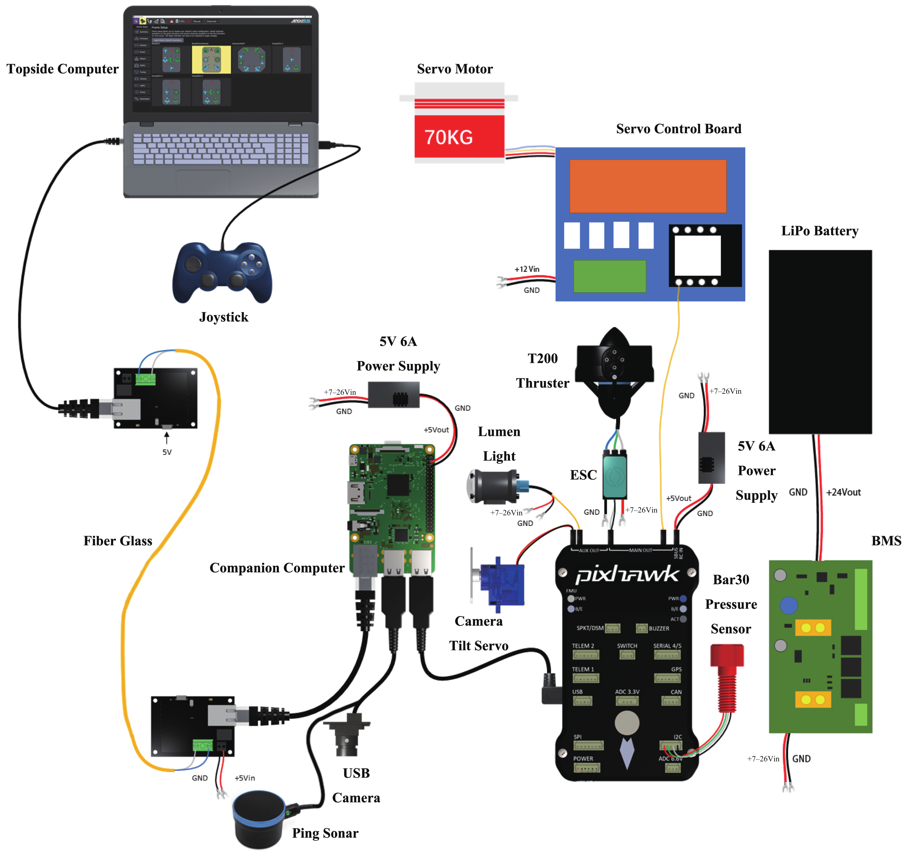
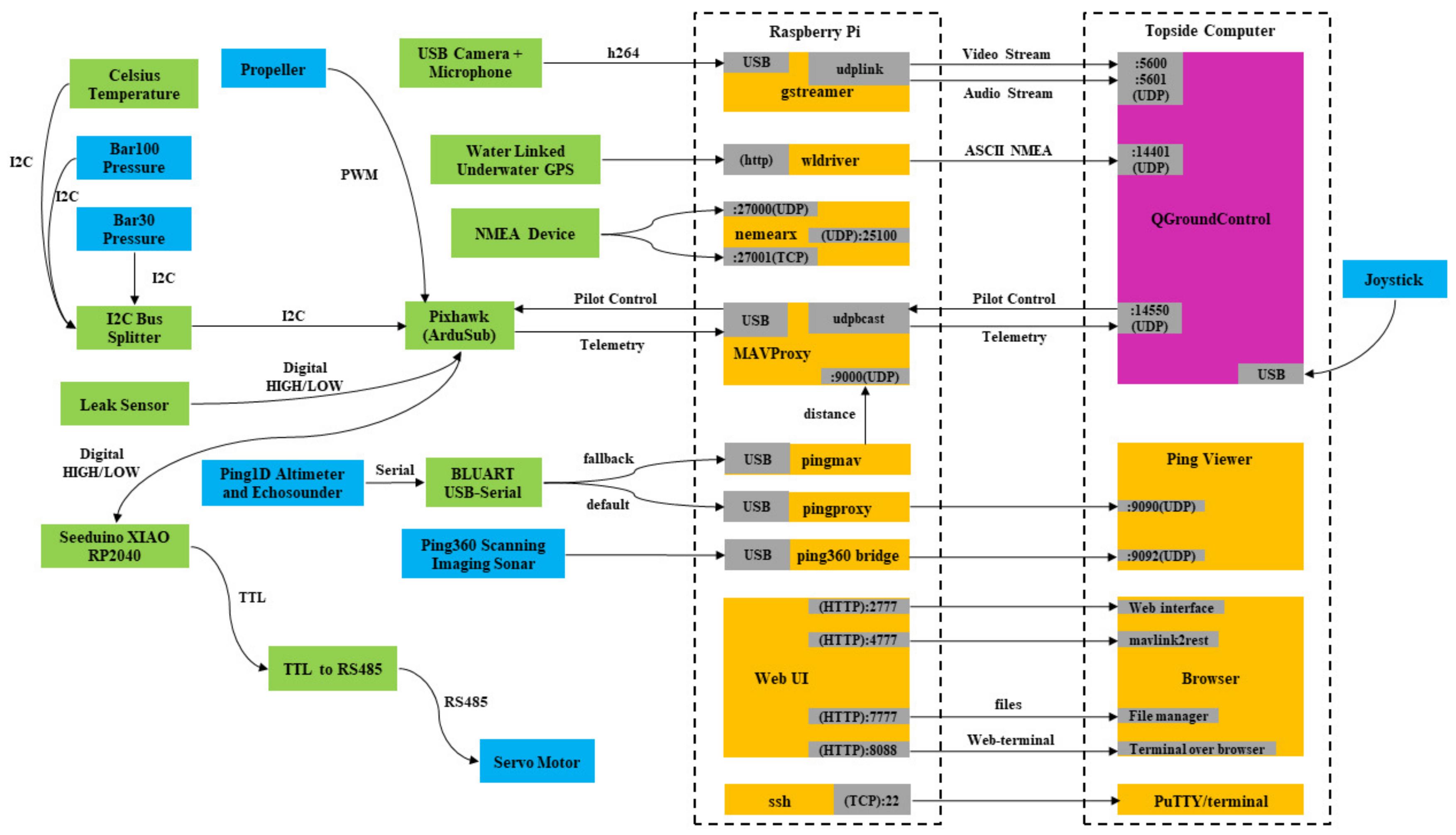
The manta ray robot is based on an ROV structure, and it uses four propellers to perform the ROV mode and four servo motors to perform the flapping mode. The technical parameters of the manta ray robot are shown in Table 1. The ROV mode is controlled with a Pixhawk and a Raspberry Pi 3B as the companion computer. The servo motors are controlled with the Seeduino XIAO RP2040. A PCB board is designed for the flapping wing control. There are a Seeduino, a DC-DC converter 12 V–5 V, a TTL to RS485 converter, and four servo sockets on the PCB board. The PCB board is sealed in a waterproof box floating on the water surface so that the rotation angle of the flapping wing could be easily adjusted. A DC power unit is connected to the PCB board, which could power the system and record the power consumption of the servo motors. The hardware connection diagram is shown in Figure 5. There is a pair of optoelectronic converters between the topside computer and the companion computer. The manta ray robot transmits the data mainly through the fiberglass. The companion computer collects all the data sending to the topside computer, including video, audio, and other data. The Pixhawk collects data such as depth, battery voltage, and current position, and it sends them to the topside computer through the MAVProxy of the companion computer. Most of the data are shown in the QGroundControl from the topside computer, and the sonar image can be seen in the Ping Viewer, as shown in Figure 6.
3. Kinematic Analysis and Hydrodynamic Analysis
3.1. Kinematic Analysis
Based on the previous work, the motion of the flapping wing and the bionic kinematics are analyzed through videos of the manta ray and birds’ locomotion. The manta ray locomotion combines the oscillation and undulation movements in both span-wise and chord-wise directions. The manta ray robot with a pair of undulations and oscillations is a simplified model of real motion by deformation where the continuous parts of the flapping wing motion with varied phase angles and amplitudes relative to each other. A simple and adaptable swimming model must be defined to understand manta ray hydrodynamic features better. In this work, roll motion is defined as the rotation along with the roll servo, while pitch motion is defined as the rotation along with the pitch servo. The flapping equation is a sinusoidal function that combines roll motion with pitch motion, which could be expressed as follows:
where and is the pitching and rolling amplitudes, f is the frequency of the flapping motion, is the phase difference between roll and pitch motion. According to the previous research, the optimum value of for the maximum efficiency is [23].
The Reynolds number (Re), the Strouhal number () and the reduced frequency () are three key parameters in hydrodynamics, which could be expressed as follows:
where is the density of the fluid, U is the free-stream velocity, c is the characteristic linear dimension (here is the chord length of the flapping wing), is the dynamic viscosity of the fluid, f is the flapping frequency, and A is the flapping amplitude.
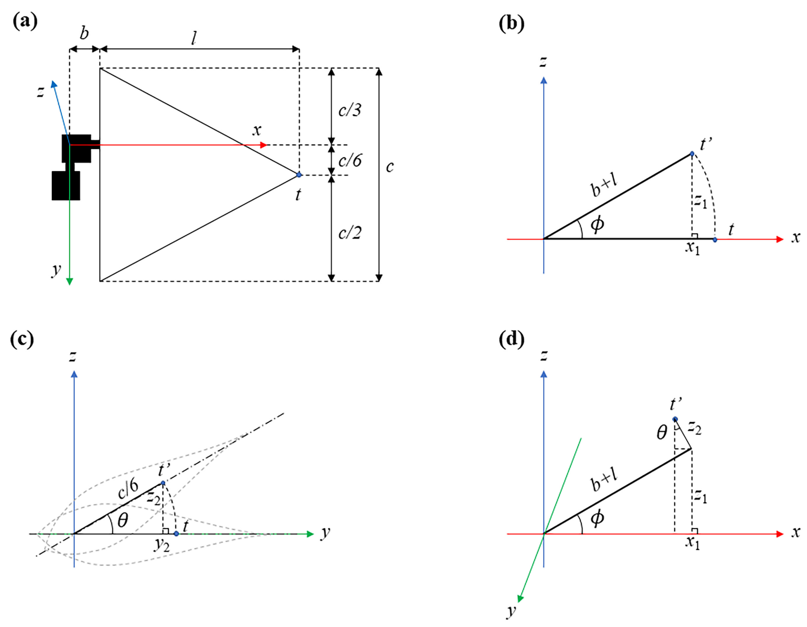
The kinematics analysis is shown in Figure 7, where t is the initial endpoint and is its presence. For the pitch motion, the center of rotation is fixed on the one third of the chord near the front, as shown in Figure 7a. Figure 7b shows the first step is to observe the roll motion from plane , and the could be expressed as follows:
where b is the distance between the axis of the roll motion and the chord of the flapping wing, l is the span of the flapping wing, is the rolling degree.
Figure 7c shows the second step is to observe the pitch motion from plane , and the could be expressed as follows:
where is the pitching degree, which is .
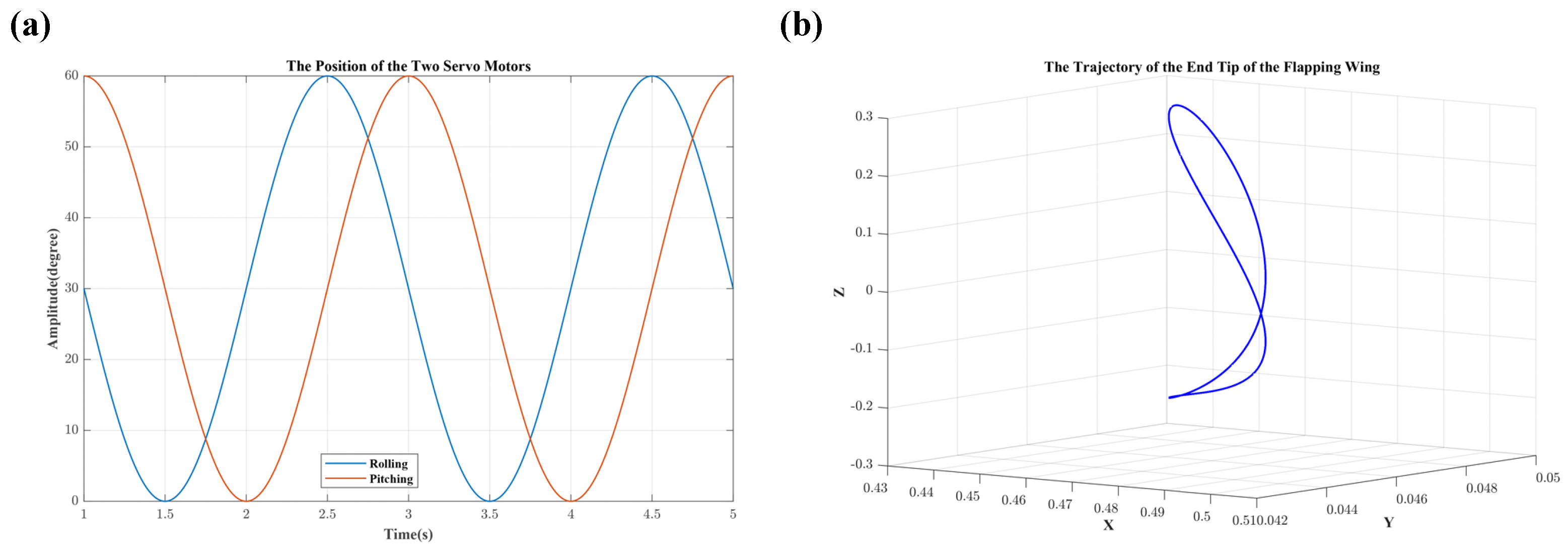
Figure 7d shows the geometry relations between roll and pitch motions. Figure 8a shows the roll () and pitch () degree, respectively. The angle velocity is . Figure 8b shows the trajectory of the end tip of the flapping wing in three-dimensional coordinate system, and the could be expressed as follows:
3.2. Hydrodynamic Analysis
In this section, the drag force variance between the manta ray robot and Blue ROV at different swimming speeds is studied. For much previous research [24,25], the manta ray model is simplified to a streamlined body with a pair of wings. Although the frontal nose, tail, and surface roughness of manta ray could be considered significant in specific circumstances, most manta ray robots are not the same as a real manta ray. In our present study, the manta ray robot is considered to be a robot that could generate a simple flapping pattern and swim like a glider.
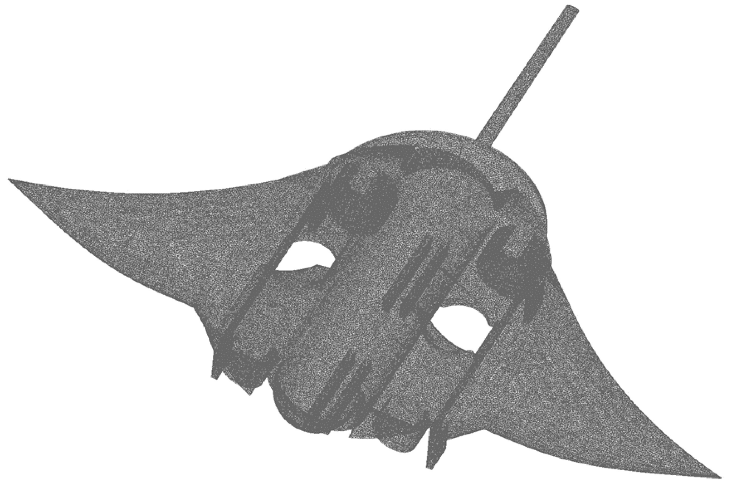
3.2.1. Mesh Generation
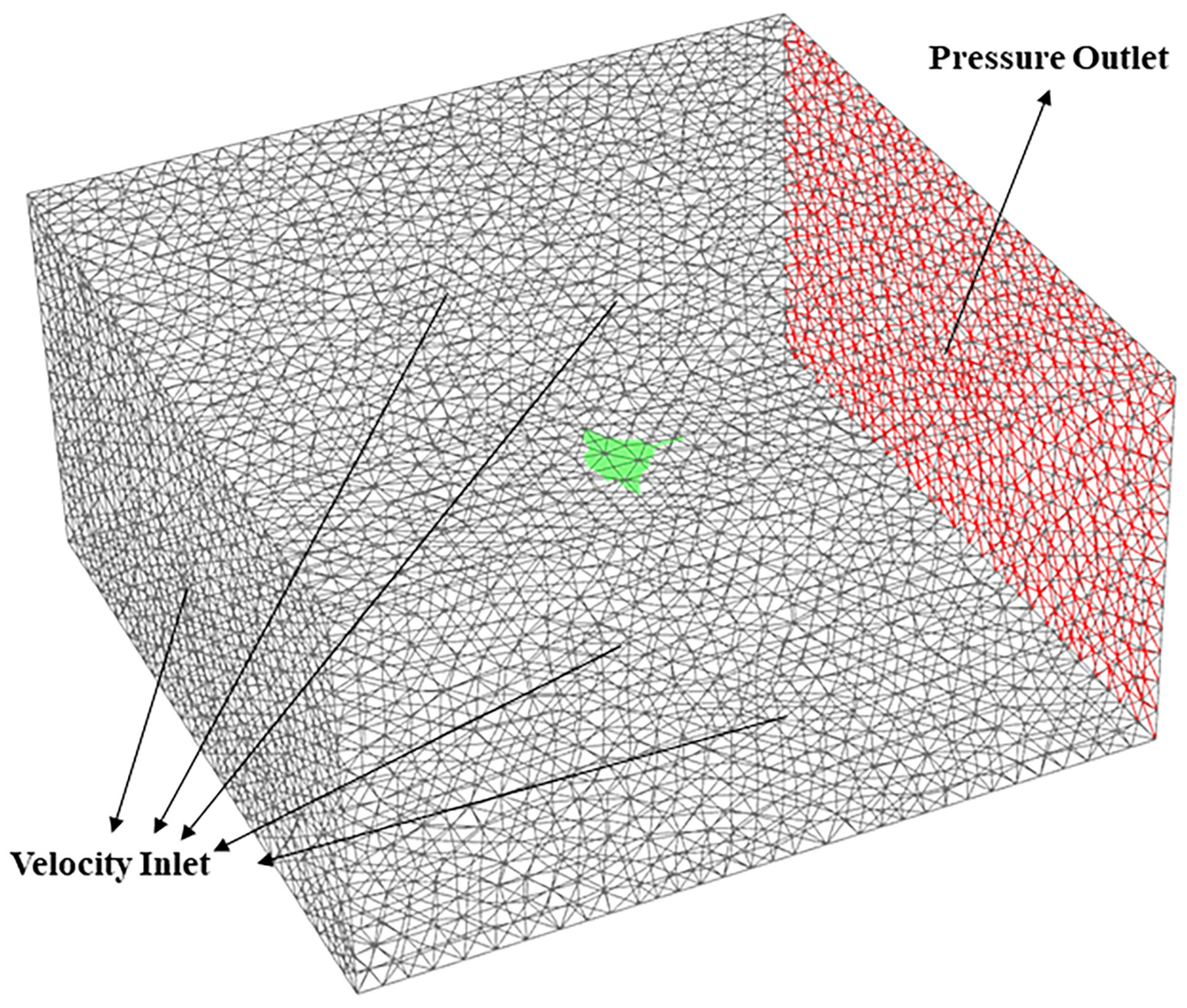
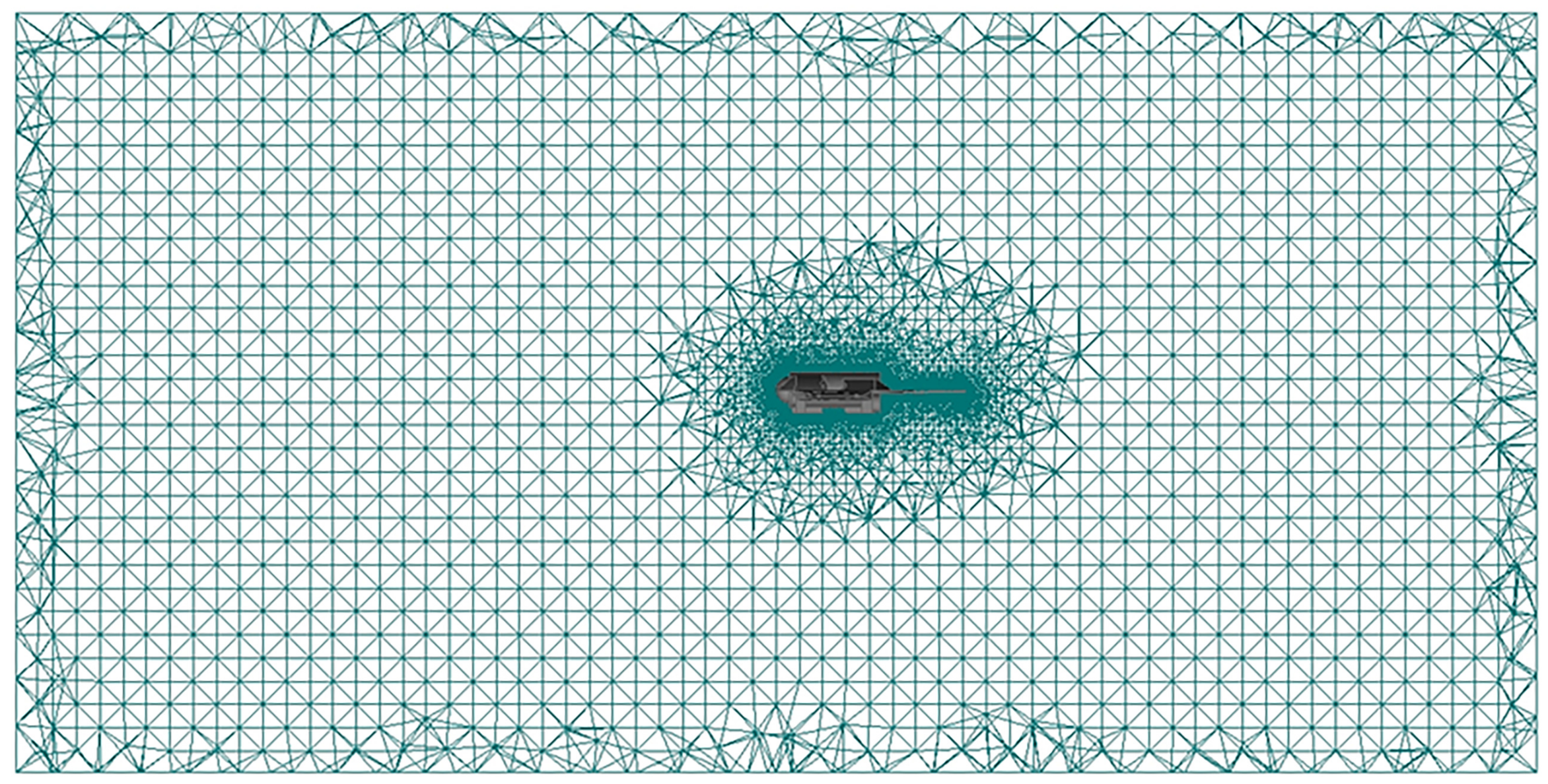
ICEM 20.0 is used to generate meshes, and balance the accuracy and calculation efficiency of the CFD method. Figure 9 shows the computational domain containing the simplified manta ray robot model. The back surface in red is set as the pressure outlet with reference pressure 0, while the other surfaces in gray are set as the velocity inlet (0.5 m/s, 1 m/s, 1.5 m/s, 2 m/s), as shown in Figure 10. The hull of the manta ray robot is defined as the wall. The distance from the origin point of the manta ray robot to the outlet boundary and the front inlet boundary is quadruple the length of the robot. The distance from the origin of the robot to the upper and bottom inlet boundaries is twice the length of the robot. The distance from the origin of the robot to the left and right inlet boundaries is triple the width of the robot. Because it is complicated to apply the structure mesh to the robot model, unstructured meshes are applied to generated elements and nodes in the computational domain, as shown in Figure 9. The mesh arrangement around the model is shown in Figure 11. The mesh size for the computational domain is 2,380,090 cells.
3.2.2. CFD Numerical Simulation
Fluent 20.0 is used as the solver, RANS equations are adopted as the control equations, and the finite volume method is applied to discrete the control equations. The turbulence model adopts the standard , and the standard wall function method is applied to treat areas near the wall. The wall in the computational domain is set as a no-slip wall. The turbulent viscosity ratio is set to 2, while the intensity for the velocity inlet and pressure outlet is 2%. The standard discretization scheme is applied to the pressure. The solution method uses the SIMPLEC algorithm. The second-order upwind scheme is applied for turbulence kinetic energy, momentum, and dissipation rate, and under-relaxation factors are set to default values.
By setting the CFD simulation parameters in the reference values module of FLUENT, the drag, lift, drag coefficient and lift coefficient can be monitored. The drag coefficient is calculated with the following equation:
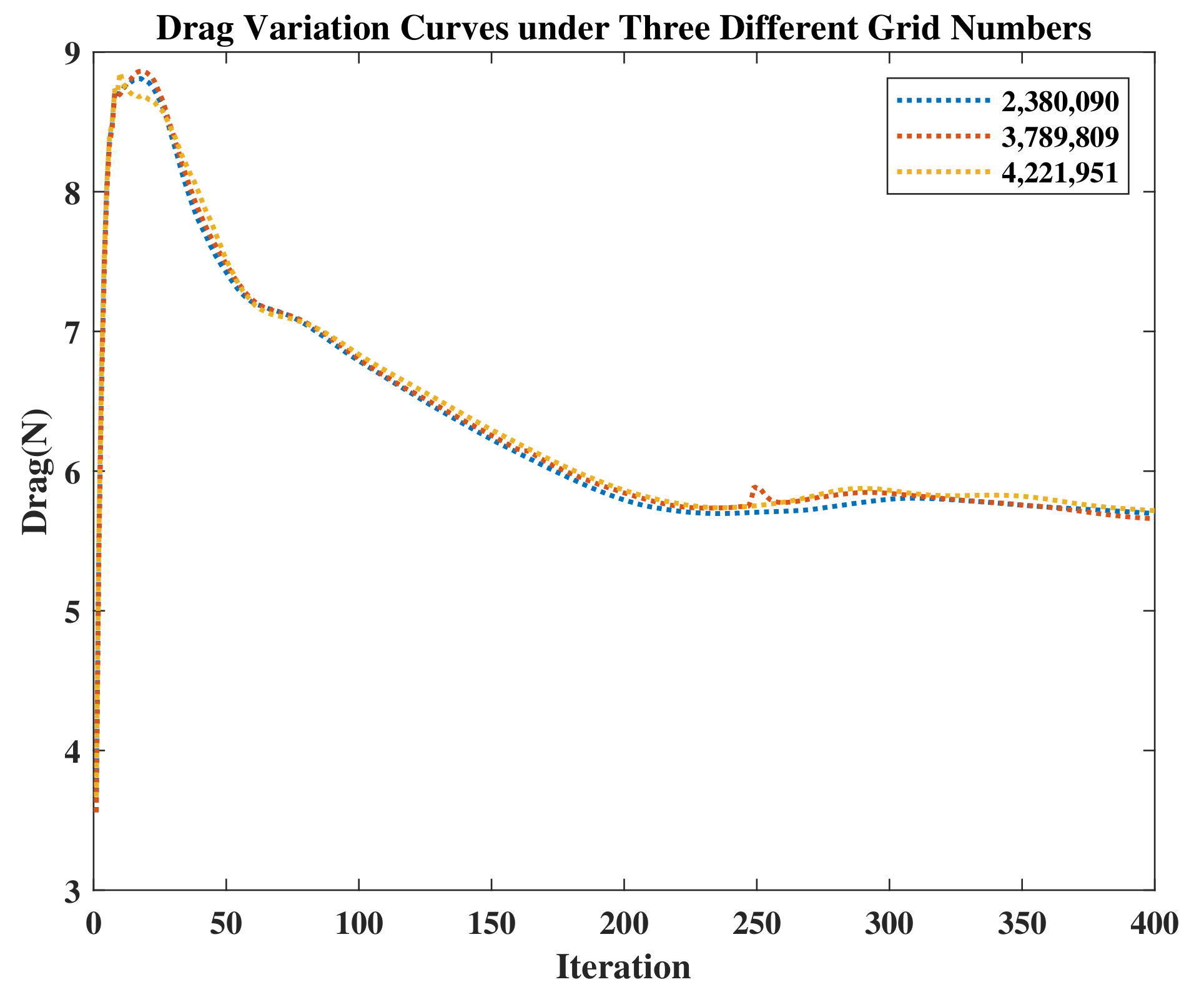
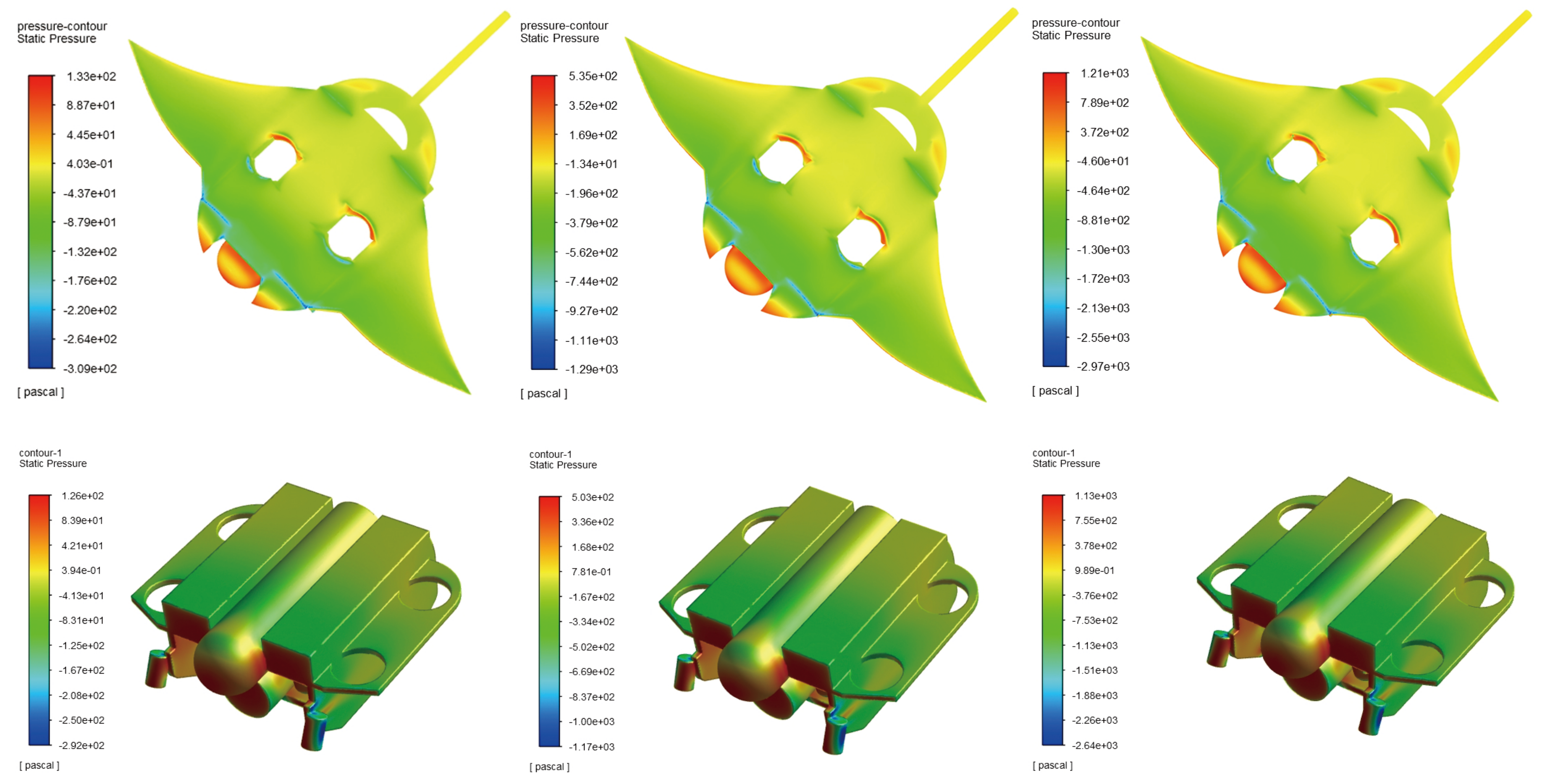
Three swimming speed sets are simulated in the manta ray robot and the Blue ROV. The drag and drag coefficient are recorded. As shown in Table 2, the drag of the manta ray robot is 32.2% less than Blue ROV while the lift is significantly greater than Blue ROV. The grid insensitivity is checked under three different grid numbers, and the drag difference is lower than 0.004%, as shown in Figure 12. The Reynolds number of the manta ray robot case under 0.5 m/s is 640,000. The contours of the static pressure with three different velocities are shown in Figure 13.
4. Experiment and Result
4.1. Experiment Setup
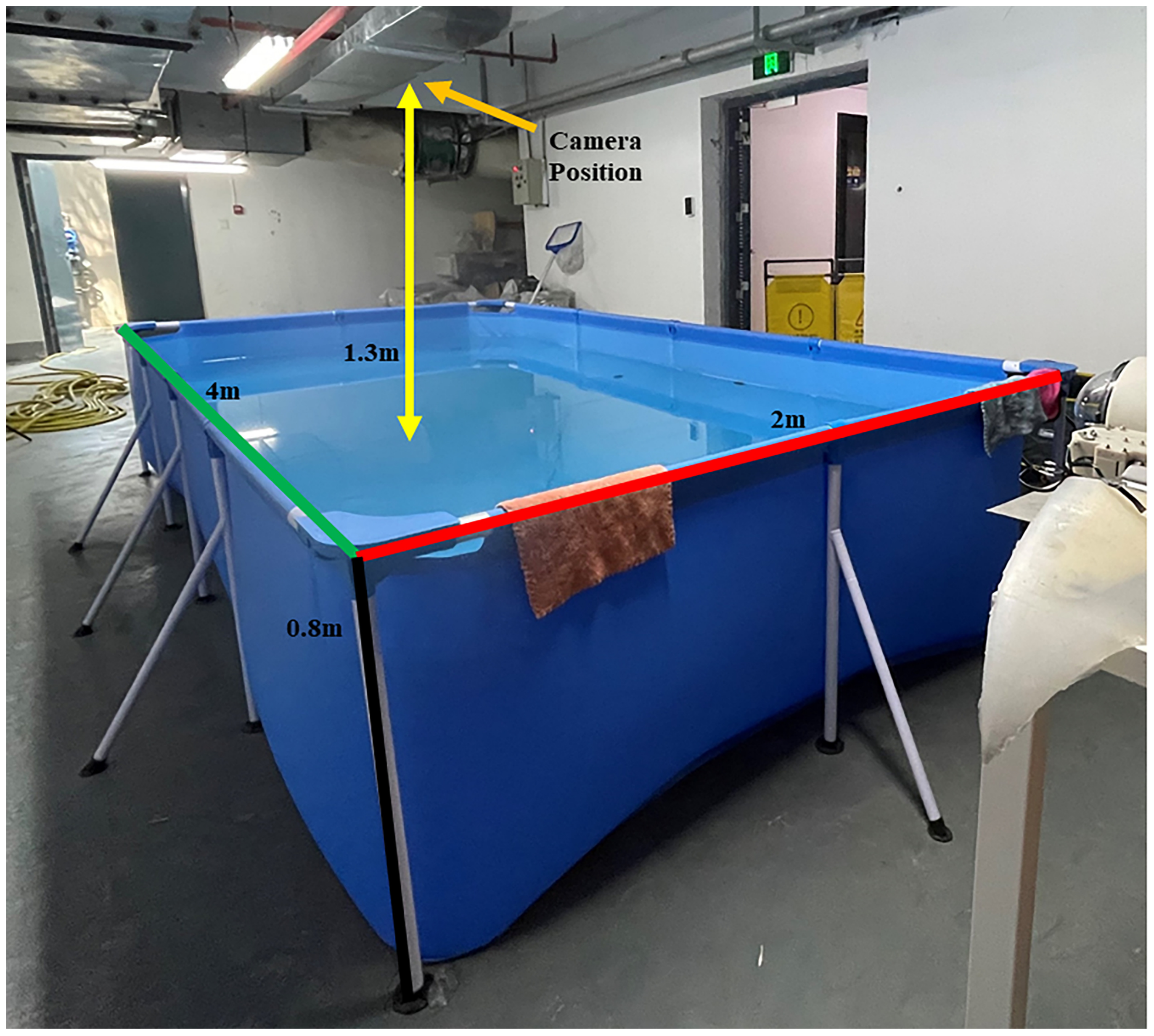
Several experiments are carried out to test the navigation speed of the manta ray robot. An enclosed swimming pool (4 m × 2 m × 0.8 m) is used to do experiment, as shown in Figure 14. A GoPro Max as a video camera is set 1.3 m away from the water surface to monitor the manta ray robot. Since the beginning and the trajectory end are easily influenced by the surroundings, the camera only records the middle part of the swimming pool, where the manta ray robot swims more stable. After the recording, Kinovea is used to analyze the video for the swimming speed of the manta ray robot.
4.2. Propulsion Performance
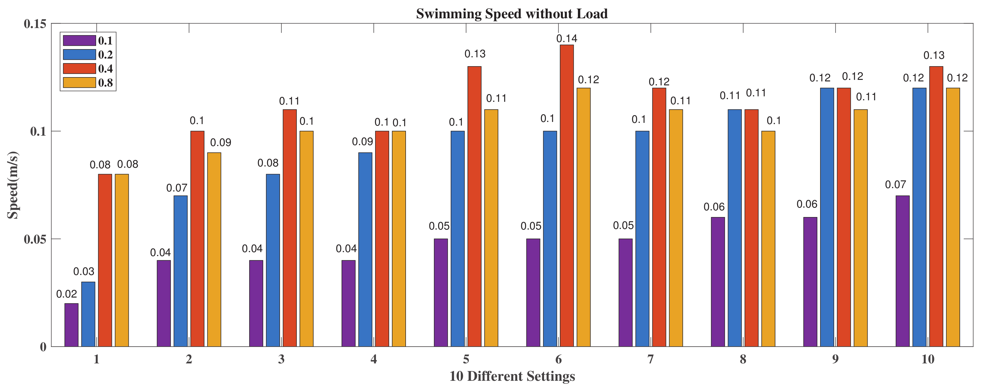
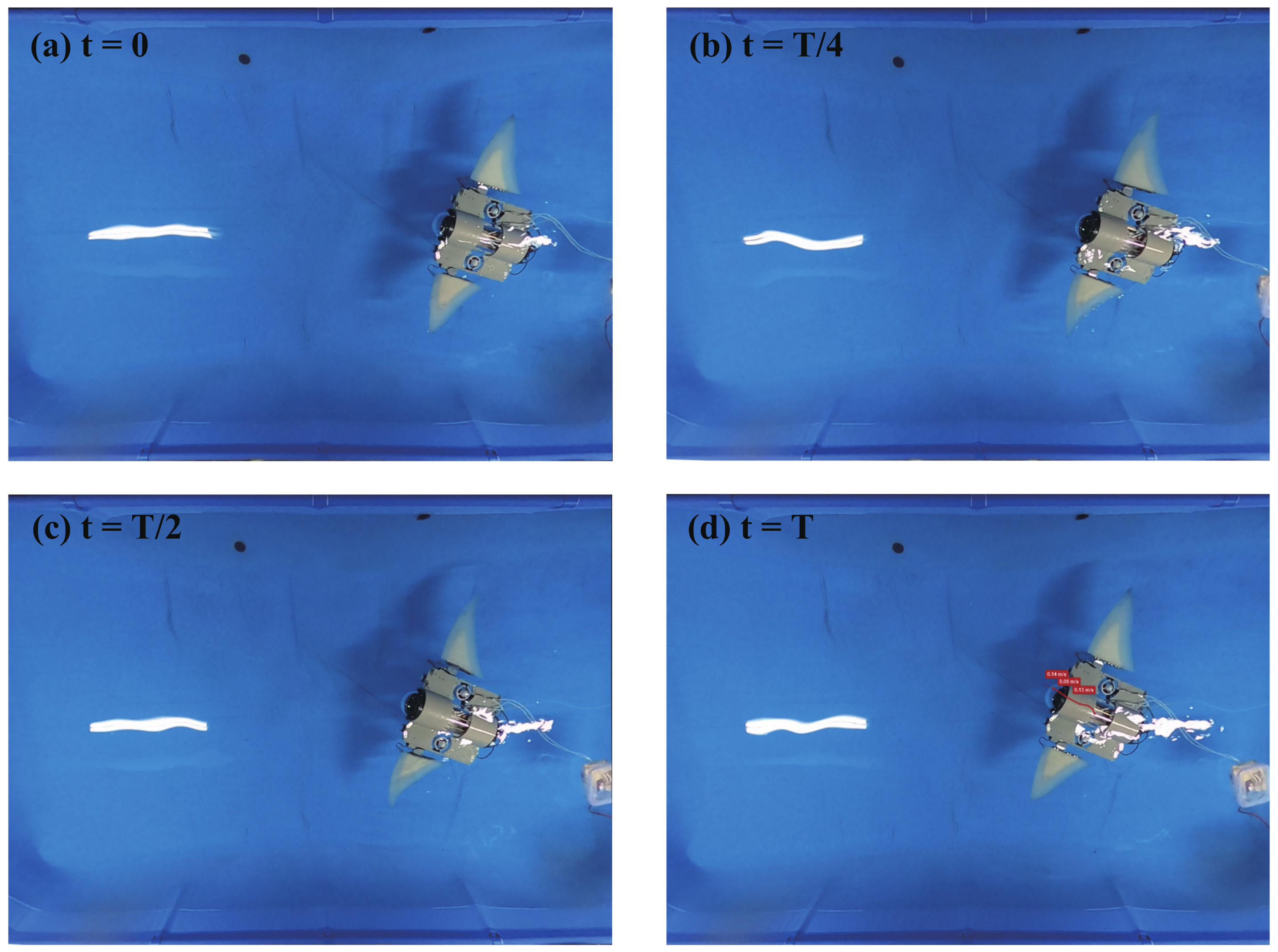
The propulsion performance of the flapping wing is tested under two scenarios, with or without load (1.5 kg). Initially, several groups of rotation angle and frequency are performed, and minor changes in the angle and frequency are found such that they have an almost negligible impact on the swimming speed. Therefore, five degrees is taken as the step and the frequency is doubled every time from 0.1 to 0.8. Ten sets of rotation angles for the pitching and rolling motions are selected as shown in Table 3. From the experiments, it is found that with the increase of the frequency, the speed of the manta ray robot increases as well. However, when the frequency is greater than 0.4 Hz, the swimming speed of the manta ray robot decreases rapidly, as shown in Figure 15. In swimming without load, case 6 with 0.4 Hz has the fastest swimming speed at 0.14 m/s, as shown in Figure 16. Furthermore, 14 different manta ray-like robots are listed in Table 4 to compare with the manta ray robot we design. From the table, it could be concluded that the manta ray robot we designed is larger than most of other manta ray-like robots while its swimming speed is faster than most smart material made robots and performs well compared with the traditional manta ray robot. Moreover, our manta ray robot was equipped with the most sensors, which means it has the most potential.
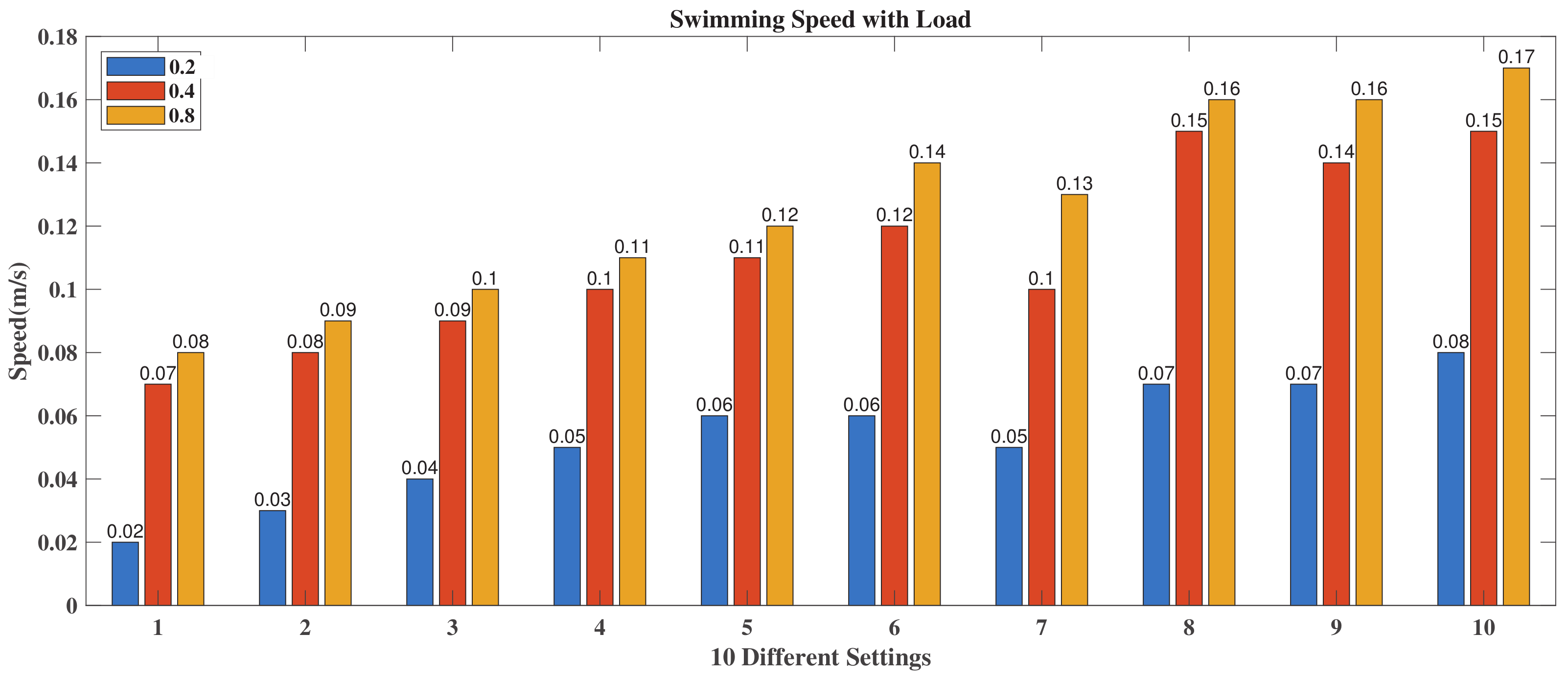
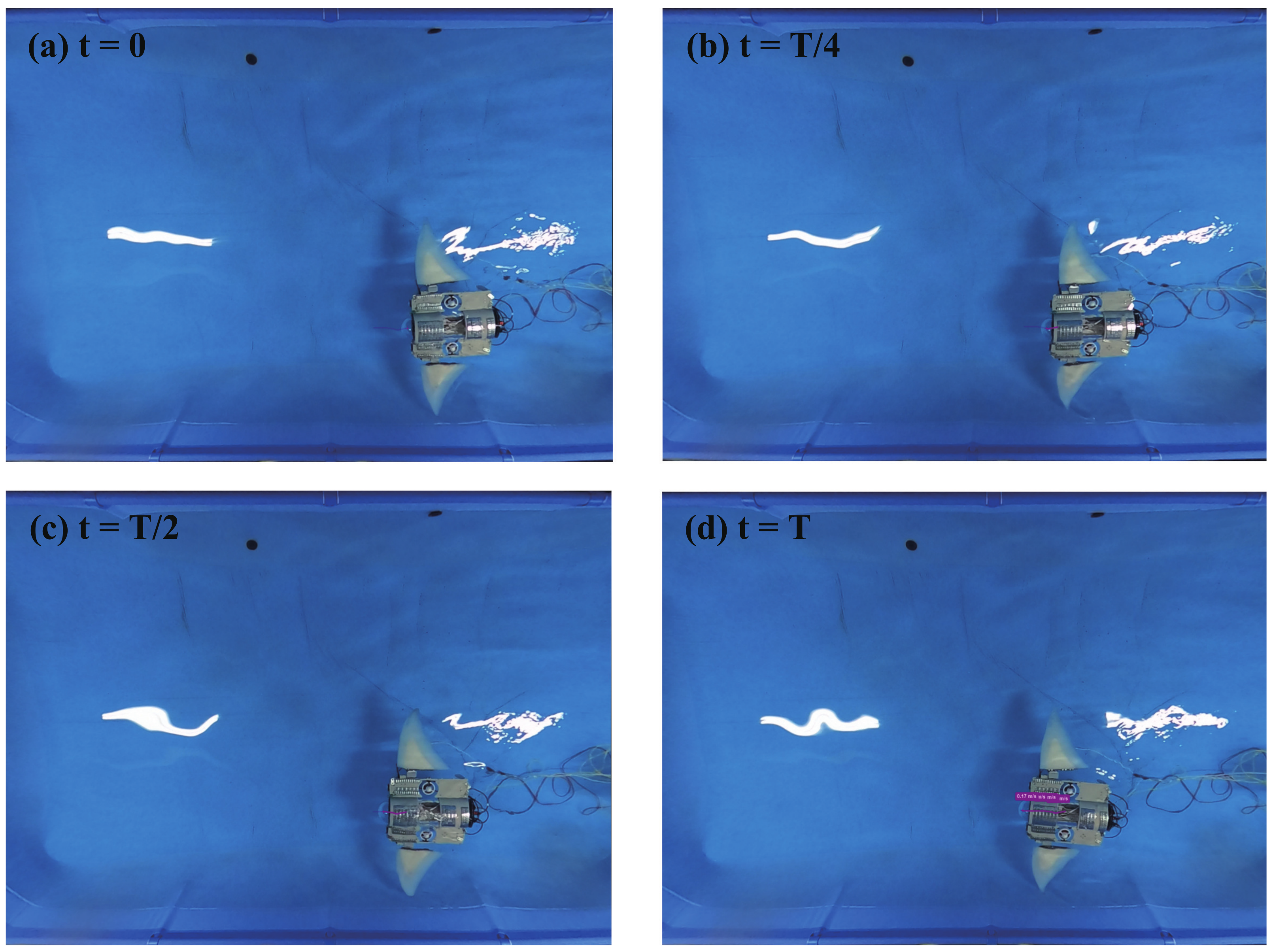
For swimming with load, the frequency of 0.1 Hz and 1.0 Hz are omitted for two reasons: (1) The speed under 0.1 Hz is too slow compared with others. (2) While the frequency is over 1 Hz, the servo motor cannot rotate to the exact position due to its limitation. In this case, the swimming speed of the manta ray robot rises with the frequency while it grows with both the rolling and pitching angles, as shown in Figure 17. The maximum swimming speed of 0.17 m/s was found in case 10 with 0.8 Hz, as shown in Figure 18. During the experiment, the manta ray robot is wholly submerged in water, so the floating center and the center of gravity retain their respective positions. This makes the restoring moment remain the same while the torque generated by the flapping wing changes over time, which leads to instability of the robot, especially in the low-frequency case the significant longitudinal sway is observed.
4.3. Maneuverability Performance
The maneuverability performance of the flapping wing is tested with different amplitudes. Since the maneuverability experiment is tested with 1.5 kg load, the frequency of 0.8 Hz is selected as it has the maximum swimming speed. For the amplitude difference, the left fin is set as stationary while the rolling amplitude of the right fin is defined from 5 to 25 degrees and the pitching amplitude is tested in 10 and 15 degrees. The phase difference is set as . The experiment video is recorded, and the turning speed and radius are analyzed with Kinovea.
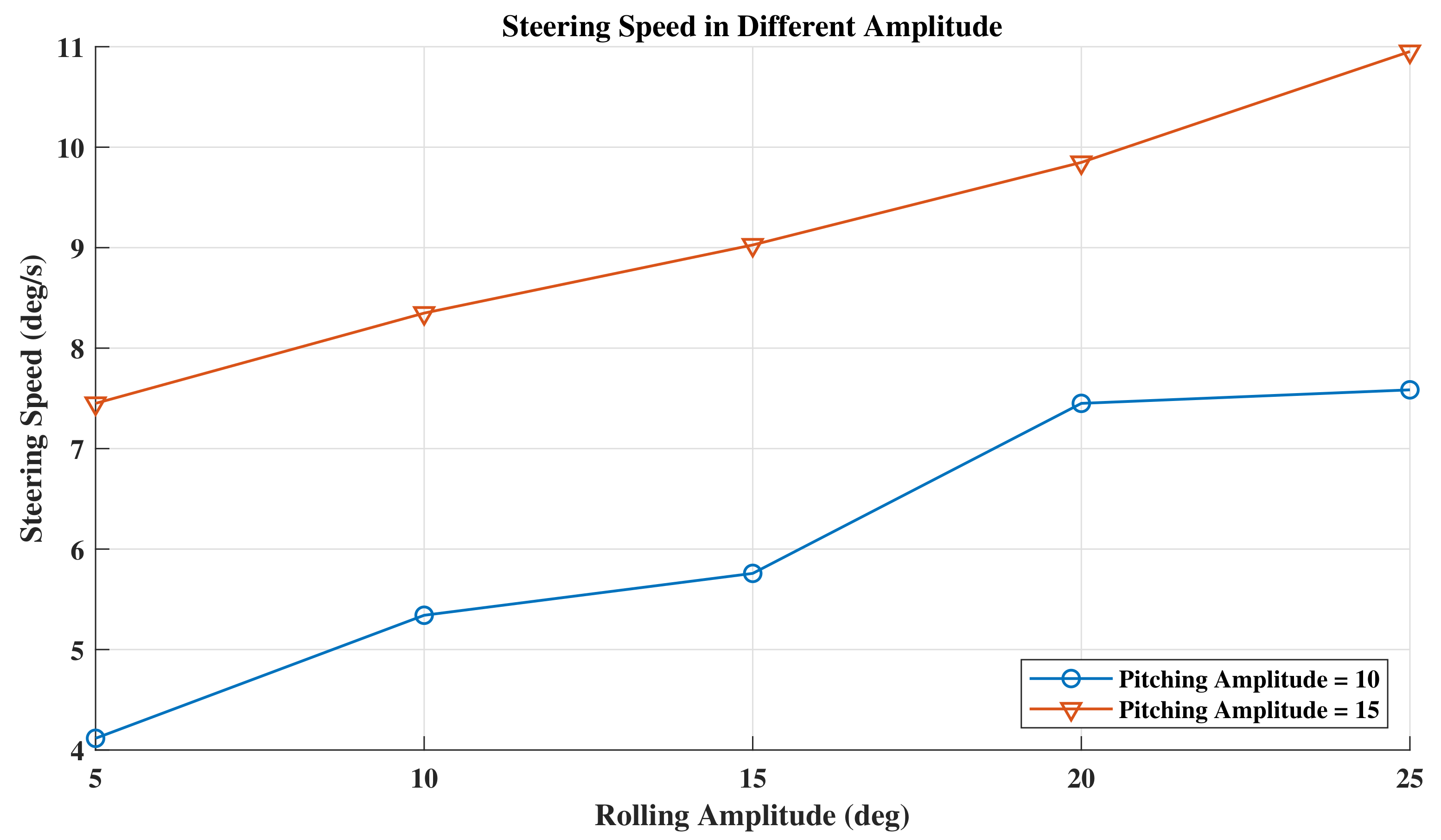
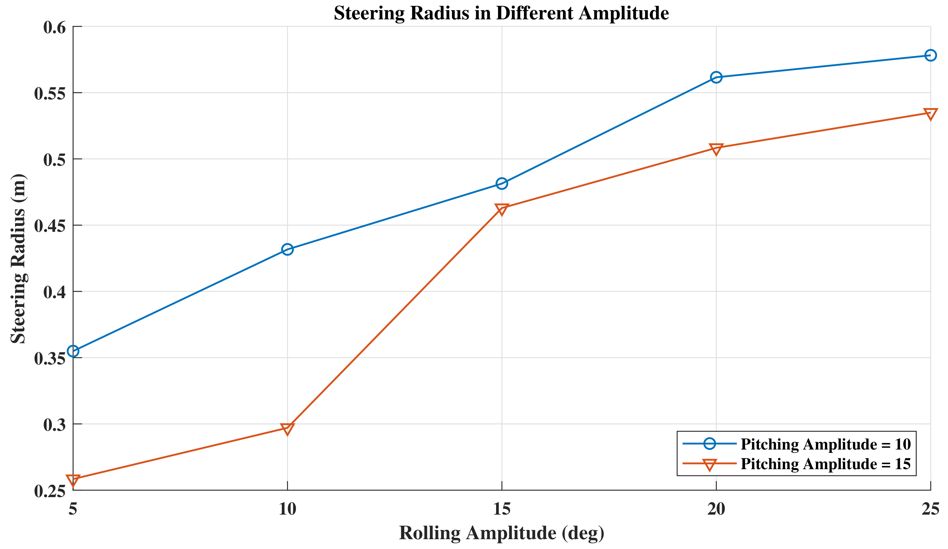
The different motion of the flapping wing creates a steering torque around the COM (Center of Mass) of the manta ray robot, which leads to the turning. Furthermore, the flapping wing is fixed on the main board near the COM, so the steering speed is relatively slow. According to Figure 19 and Figure 20, the steering speed goes up steadily when the rolling amplitude increases from 5 to 25, and it also rises when the pitching amplitude grows up. Since the thrust grows with the amplitude, the result shows the same as the propulsion performance. The steering radius increases with the rolling amplitude because when the thrust grows, the manta ray robot has a downward tilt, so although the steering speed increases, the radius does not decrease. However, the radius decreases when the pitching amplitude increases since the drag increase with the pitching amplitude.
5. Conclusions and Future Work
This paper reports a manta ray robot with a pair of flexible pectoral fins based on an open-source ROV. Three kinds of materials are applied to manufacture the flapping wing structure to mimic the stiffness of the real manta ray’s bone, muscle, and skin. The flapping wing motion is analyzed, while the hydrodynamic performance of the manta ray robot is simulated and compared with the Blue ROV. With simple rolling and pitching movement, the manta ray robot can use the flexible flapping wing for swimming forward and steering. Both the with load and without load experiments are performed, and an upward trend of the swimming speed with increased frequency is concluded. However, the swimming speed drops rapidly when the frequency exceeds a specific number. For example, when the frequency is over 0.4 Hz in unload conditions, the swimming speed would decrease in most cases. The steering performance experiment shows that with the increase of the amplitude the steering speed rises. Furthermore, the steering radius is positive correlation with the rolling amplitude. The manta ray robot’s depth sensor and altimeter are installed to operate the depth or height-fixed navigation.
Although the manta ray robot performed well, some aspects are worth further study. Though different materials are applied in this work, the influence of the pectoral material on the swimming performance was not investigated in-depth, which deserves further study. Furthermore, diverse materials and stiffness distributions will be tested to study the relationship with the swimming speed. The steering performance was not studied further and the phase difference mode will be tested in future work. Besides, the intelligent control algorithms are not yet applied to the manta ray robot. Motion control in complex environments is also a focus of future research. To date, the low-frequency transmission is tested and could be applied at the shallow water depth with stable communication through the water surface. Since the current robot uses optical fibers as the transmit unit, a remote-controlled manta ray robot will be developed.
Author Contributions
Supervision, W.C.; Writing—original draft, Q.L.; Writing—review & editing, W.C., R.L. and W.L.; Material Mechanical Properties Testing, Z.W.; CFD simulation, H.C.; Picture rendering, Q.H.; Experiment, Q.L. and L.C. All authors have read and agreed to the published version of the manuscript.
Funding
This research was supported by Guangdong Key R&D Program of 2021 Ocean Six Industrial project No. 2021-45, the Construction of a Leading Innovation Team project by the Hangzhou Municipal government, the Startup funding of New-joined PI of Westlake University with Grant Number (041030150118), the Priority Postdoctoral Projects in Zhejiang Province, China (Grant No. ZJ2021046).
Institutional Review Board Statement
Not applicable.
Informed Consent Statement
Not applicable.
Data Availability Statement
Not applicable.
Conflicts of Interest
The authors declare no conflict of interest.
Abbreviations
The following abbreviations are used in this manuscript:
| ROV | Remotely Operated Vehicle |
| AUV | Autonomous Underwater Vehicle |
| LW PLA | Light Weight Polylactic Acid |
| BCF | Body and/or Caudal Fin |
| MPF | Middle and/or Paired Fin |
| DPIV | Digital Particle Image Velocity |
| BEM | Boundary Element Method |
| SMA | Shape Memory Alloy |
| IPMC | Ion-exchange Polymer-metal Composite |
| DE | Dielectric Elastomer |
| RANS | Reynolds Average Navier–Stokes |
| SIMPLEC | SIMPLE Consistent |
| PCB | Printed Circuit Board |
| DC | Direct Current |
| COM | Center of Mass |
References
- Chang, E.; Matloff, L.Y.; Stowers, A.K.; Lentink, D. Soft biohybrid morphing wings with feathers underactuated by wrist and finger motion. Sci. Robot. 2020, 5, eaay1246. [Google Scholar] [CrossRef] [PubMed]
- Aureli, M.; Kopman, V.; Porfiri, M. Free-locomotion of underwater vehicles actuated by ionic polymer metal composites. IEEE/ASME Trans. Mechatron. 2009, 15, 603–614. [Google Scholar] [CrossRef]
- Sun, K.; Cui, W.; Chen, C. Review of Underwater Sensing Technologies and Applications. Sensors 2021, 21, 7849. [Google Scholar] [CrossRef] [PubMed]
- Chen, H.; Zhu, C.A.; Yin, X.Z.; Xing, X.Z.; Cheng, G. Hydrodynamic analysis and simulation of a swimming bionic robot tuna. J. Hydrodyn. 2007, 19, 412–420. [Google Scholar] [CrossRef]
- Triantafyllou, M.S.; Weymouth, G.D.; Miao, J. Biomimetic survival hydrodynamics and flow sensing. Annu. Rev. Fluid Mech. 2016, 48, 1–24. [Google Scholar] [CrossRef] [Green Version]
- Sfakiotakis, M.; Lane, D.M.; Davies, J.B.C. Review of fish swimming modes for aquatic locomotion. IEEE J. Ocean. Eng. 1999, 24, 237–252. [Google Scholar] [CrossRef] [Green Version]
- Hoar, W.; Randall, D. Fish Physiology. Locomotion; Academic Press: New York, NY, USA, 1978; Volume VII. [Google Scholar]
- Davis, H. Mechanization of Rajiform Swimming Motion: The Making of Robo-Ray; Student Project; University of British Columbia Engineering Physics Project Laboratory: Vancouver, BC, Canada, 2002. [Google Scholar]
- Schaefer, J.T.; Summers, A.P. Batoid wing skeletal structure: Novel morphologies, mechanical implications, and phylogenetic patterns. J. Morphol. 2005, 264, 298–313. [Google Scholar] [CrossRef]
- Dewey, P.A.; Carriou, A.; Smits, A.J. On the relationship between efficiency and wake structure of a batoid-inspired oscillating fin. J. Fluid Mech. 2012, 691, 245–266. [Google Scholar] [CrossRef]
- Fish, F.E.; Schreiber, C.M.; Moored, K.W.; Liu, G.; Dong, H.; Bart-Smith, H. Hydrodynamic performance of aquatic flapping: Efficiency of underwater flight in the manta. Aerospace 2016, 3, 20. [Google Scholar] [CrossRef] [Green Version]
- Gao, J.; Bi, S.; Xu, Y.; Liu, C. Development and design of a robotic manta ray featuring flexible pectoral fins. In Proceedings of the 2007 IEEE International Conference on Robotics and Biomimetics (ROBIO), Sanya, China, 15–18 December; pp. 519–523.
- Niu, C.; Zhang, L.; Bi, S.; Cai, Y. Development and depth control of a robotic fish mimicking cownose ray. In Proceedings of the 2012 IEEE International Conference on Robotics and Biomimetics (ROBIO), Guangzhou, China, 11–14 December 2012; pp. 814–818. [Google Scholar]
- Cai, Y.; Bi, S.; Zhang, L.; Gao, J. Design of a robotic fish propelled by oscillating flexible pectoral foils. In Proceedings of the 2009 IEEE/RSJ International Conference on Intelligent Robots and Systems, St. Louis, MO, USA, 10–15 October 2009; pp. 2138–2142. [Google Scholar]
- Beal, D.; Hover, F.; Triantafyllou, M.; Liao, J.; Lauder, G.V. Passive propulsion in vortex wakes. J. Fluid Mech. 2006, 549, 385–402. [Google Scholar] [CrossRef] [Green Version]
- Quinn, D.; Lauder, G. Tunable stiffness in fish robotics: Mechanisms and advantages. Bioinspir. Biomimetics 2021, 17, 011002. [Google Scholar] [CrossRef] [PubMed]
- Chen, Z.; Um, T.I.; Zhu, J.; Bart-Smith, H. Bio-inspired robotic cownose ray propelled by electroactive polymer pectoral fin. In Proceedings of the ASME International Mechanical Engineering Congress and Exposition, Denver, CO, USA, 11–17 November 2011; Volume 54884, pp. 817–824. [Google Scholar]
- Li, T.; Li, G.; Liang, Y.; Cheng, T.; Dai, J.; Yang, X.; Liu, B.; Zeng, Z.; Huang, Z.; Luo, Y.; et al. Fast-moving soft electronic fish. Sci. Adv. 2017, 3, e1602045. [Google Scholar] [CrossRef] [PubMed] [Green Version]
- Li, G.; Chen, X.; Zhou, F.; Liang, Y.; Xiao, Y.; Cao, X.; Zhang, Z.; Zhang, M.; Wu, B.; Yin, S.; et al. Self-powered soft robot in the Mariana Trench. Nature 2021, 591, 66–71. [Google Scholar] [CrossRef]
- Meng, Y.; Wu, Z.; Dong, H.; Wang, J.; Yu, J. Toward a novel robotic manta with unique pectoral fins. IEEE Trans. Syst. Man Cybern. Syst. 2020, 52, 1663–1673. [Google Scholar] [CrossRef]
- Cai, Y.; Chen, L.; Bi, S.; Li, G.; Zhang, H. Bionic flapping pectoral fin with controllable spatial deformation. J. Bionic Eng. 2019, 16, 916–930. [Google Scholar] [CrossRef]
- Ashraf, M.; Young, J.; Lai, J. Reynolds number, thickness and camber effects on flapping airfoil propulsion. J. Fluids Struct. 2011, 27, 145–160. [Google Scholar] [CrossRef]
- Lin, X.; Wu, J.; Zhang, T. Performance investigation of a self-propelled foil with combined oscillating motion in stationary fluid. Ocean Eng. 2019, 175, 33–49. [Google Scholar] [CrossRef]
- Cai, Y.; Ren, X.; Bi, S.; Li, G.; Hildre, H.P.; Zhang, H. Hydrodynamic development of a bionic pectoral fin for undersea monitoring platform. Ships Offshore Struct. 2019, 14, 91–99. [Google Scholar] [CrossRef]
- Macias, M.M.; Souza, I.F.; Brasil, A.C.P., Jr.; Oliveira, T.F. Three-dimensional viscous wake flow in fish swimming—A CFD study. Mech. Res. Commun. 2020, 107, 103547. [Google Scholar] [CrossRef]
- Wang, Z.; Wang, Y.; Li, J.; Hang, G. A micro biomimetic manta ray robot fish actuated by SMA. In Proceedings of the 2009 IEEE International Conference on Robotics and Biomimetics (ROBIO), Guilin, China, 19–23 December 2009; pp. 1809–1813. [Google Scholar]
- Chen, Z.; Um, T.I.; Bart-Smith, H. Bio-inspired robotic manta ray powered by ionic polymer–metal composite artificial muscles. Int. J. Smart Nano Mater. 2012, 3, 296–308. [Google Scholar] [CrossRef] [Green Version]
- Y Alvarado, P.V.; Chin, S.; Larson, W.; Mazumdar, A.; Youcef-Toumi, K. A soft body under-actuated approach to multi degree of freedom biomimetic robots: A stingray example. In Proceedings of the 2010 3rd IEEE RAS & EMBS International Conference on Biomedical Robotics and Biomechatronics, Tokyo, Japan, 26–29 September 2010; pp. 473–478. [Google Scholar]
- Chew, C.M.; Lim, Q.Y.; Yeo, K. Development of propulsion mechanism for Robot Manta Ray. In Proceedings of the 2015 IEEE International Conference on Robotics and Biomimetics (ROBIO), Zhuhai, China, 6–9 December 2015; pp. 1918–1923. [Google Scholar]
- Yang, S.b.; Qiu, J.; Han, X.y. Kinematics modeling and experiments of pectoral oscillation propulsion robotic fish. J. Bionic Eng. 2009, 6, 174–179. [Google Scholar] [CrossRef]
- Zhou, C.; Low, K. Design and locomotion control of a biomimetic underwater vehicle with fin propulsion. IEEE/ASME Trans. Mechatron. 2011, 17, 25–35. [Google Scholar] [CrossRef]
- Low, K.; Zhou, C.; Seet, G.; Bi, S.; Cai, Y. Improvement and testing of a robotic manta ray (RoMan-III). In Proceedings of the 2011 IEEE International Conference on Robotics and Biomimetics, Karon Beach, Thailand, 7–11 December 2011; pp. 1730–1735. [Google Scholar]
- Punning, A.; Anton, M.; Kruusmaa, M.; Aabloo, A. A biologically inspired ray-like underwater robot with electroactive polymer pectoral fins. In Proceedings of the International IEEE Conference on Mechatronics and Robotics, Istanbul, Turkey, 5 June 2004; Volume 2004, pp. 241–245. [Google Scholar]
- Takagi, K.; Yamamura, M.; Luo, Z.W.; Onishi, M.; Hirano, S.; Asaka, K.; Hayakawa, Y. Development of a rajiform swimming robot using ionic polymer artificial muscles. In Proceedings of the 2006 IEEE/RSJ International Conference on Intelligent Robots and Systems, Beijing, China, 9–15 October 2006; pp. 1861–1866. [Google Scholar]
- Krishnamurthy, P.; Khorrami, F.; De Leeuw, J.; Porter, M.; Livingston, K.; Long, J. An electric ray inspired biomimetic autonomous underwater vehicle. In Proceedings of the 2010 American Control Conference, Baltimore, MD, USA, 30 June–2 July 2010; pp. 5224–5229. [Google Scholar]
- Park, S.J.; Gazzola, M.; Park, K.S.; Park, S.; Di Santo, V.; Blevins, E.L.; Lind, J.U.; Campbell, P.H.; Dauth, S.; Capulli, A.K.; et al. Phototactic guidance of a tissue-engineered soft-robotic ray. Science 2016, 353, 158–162. [Google Scholar] [CrossRef] [PubMed] [Green Version]
Figure 1.
Comparison of the flapping wing of biological and bionic manta rays. (a) Cleared and stained embryo of Gymnura marmorata. Reprinted/adapted with permission from Ref. [9]. Copyright 2005 John Wiley and Sons. (b) the soft material-based flapping wing structure.
Figure 1.
Comparison of the flapping wing of biological and bionic manta rays. (a) Cleared and stained embryo of Gymnura marmorata. Reprinted/adapted with permission from Ref. [9]. Copyright 2005 John Wiley and Sons. (b) the soft material-based flapping wing structure.

Figure 2.
The overall shape of the manta ray robot and different layers of wing structure.

Figure 3.
Strain-stress curve of four different silicone rubbers.

Figure 4.
The connection between the flapping wing and the main body.

Figure 5.
Hardware connection diagram.

Figure 6.
Software protocol diagram.

Figure 7.
The kinematics analysis of the flapping wing. (a) Top view of the flapping wing. (b) Roll motion at plane . (c) Pitch motion at plane . (d) Combined motion in three-dimensional coordinate system.
Figure 7.
The kinematics analysis of the flapping wing. (a) Top view of the flapping wing. (b) Roll motion at plane . (c) Pitch motion at plane . (d) Combined motion in three-dimensional coordinate system.

Figure 8.
The trajectory of the flapping wing. (a) The position of the two servo motors. (b) The trajectory of the end tip of the flapping wing.
Figure 8.
The trajectory of the flapping wing. (a) The position of the two servo motors. (b) The trajectory of the end tip of the flapping wing.

Figure 9.
The body mesh of the manta ray robot.

Figure 10.
Computational domain of the manta ray robot.

Figure 11.
Mesh arrangement around the manta ray robot.

Figure 12.
Contours of drag variation curves under three different grid numbers.

Figure 13.
Contours of static pressure with different velocity.

Figure 14.
The swimming pool used in the experiment.

Figure 15.
Swimming speed without loads.

Figure 16.
The experiment without in the swimming pool, f = 0.4 Hz, = 25, = 20.

Figure 17.
Swimming speed with loads.

Figure 18.
The experiment with load in the swimming pool, f = 0.8 Hz, = 30, = 25.

Figure 19.
Steering speed in different amplitude.

Figure 20.
Steering radius in different amplitude.


Table 1.
The technical parameters of the bionic manta ray robot.
| Items | Characteristics |
|---|---|
| Dimension () | 1000 mm × 1280 mm × 205 mm |
| Total mass | 12 kg |
| Maximum navigation depth | 100 m |
| Sensors | Gyroscope, depth sensor and altimeter |
| Drive mode | Servomotors (7 Nm, 60 /s) and propellers (2 kg) |
| Control mode | Optical fiber and remote |
| Power supply | Li-Po battery (22.2 V) |
| Operation time | 2 h at cruising speed |
| Speed | 1 kn/s |
Table 2.
The results of the numerical simulation.
| Item | Swimming Speed (m/s) | Drag (N) | Cd |
|---|---|---|---|
| ROV | 0.5 | 8.2208 | 0.071327 |
| 1 | 32.6880 | 0.070904 | |
| 1.5 | 73.3280 | 0.070691 | |
| Manta Ray Robot | 0.5 | 5.6955 | 0.036827 |
| 1 | 22.1300 | 0.035773 | |
| 1.5 | 49.6250 | 0.035652 |
Table 3.
The rotation amplitude of 10 different experiments.
| Case Number | Rolling Amplitude | Pitching Amplitude |
|---|---|---|
| 1 | 15 | 10 |
| 2 | 20 | 10 |
| 3 | 20 | 15 |
| 4 | 25 | 10 |
| 5 | 25 | 15 |
| 6 | 25 | 20 |
| 7 | 30 | 10 |
| 8 | 30 | 15 |
| 9 | 30 | 20 |
| 10 | 30 | 25 |
Table 4.
Comparison with other manta ray type robot.
| Robotic Systems | Mass (kg) | Length (m) | Speed (m/s) |
|---|---|---|---|
| The Manta Ray Robot | 12 | = (1.0 × 1.28 × 0.205) | 0.17 |
| Robo-Ray III [13] | 3.4 | = (0.56 × 0.12 × 0.643) | 0.32 |
| Micro Manta Ray (SMA) [26] | 0.354 | = (0.133 × 0.22) | 0.057 |
| IPMC Manta Ray [27] | 0.055 | 0.11 | 0.007 |
| Soft Body Single-Dual Actuator Ray [28] | 0.486 | 0.225 | 0.08 |
| Flexible Pectoral Foil Cownose Ray [14] | N/A | = (0.33 × 0.55) | 0.2 |
| Bionic Fin Manta Ray [29] | 0.7677 | = (0.28 × 0.58) | 0.45 |
| Cownose Ray-I [30] | 1 | = (0.3 × 0.5) | 0.15 |
| RoMan-II [31] | 7.3 | 1 | 0.4 |
| RoMan-III [32] | 5 | 0.88 | 0.3 |
| Manta Ray Robot [12] | 3.4 | = (0.5 × 0.6) | 0.7 |
| IPMC Chain Ribbed Ray [33] | 0.066 | N/A | 0.000005 |
| Multi-Ribbed IPMC [34] | 0.315 | N/A | 0.015 |
| RayBot (Electric Ray Caudal Fin Propulsion Robot) [35] | 5.5 | 0.75 | 0.1 |
| Soft-Robotic Ray + Tissue-engineered (1/10 scale) [36] | N/A | Diameter = 0.01 | 0.001 |
Publisher’s Note: MDPI stays neutral with regard to jurisdictional claims in published maps and institutional affiliations. |
© 2022 by the authors. Licensee MDPI, Basel, Switzerland. This article is an open access article distributed under the terms and conditions of the Creative Commons Attribution (CC BY) license (https://creativecommons.org/licenses/by/4.0/).
Share and Cite
MDPI and ACS Style
Liu, Q.; Chen, H.; Wang, Z.; He, Q.; Chen, L.; Li, W.; Li, R.; Cui, W. A Manta Ray Robot with Soft Material Based Flapping Wing. J. Mar. Sci. Eng. 2022, 10, 962. https://doi.org/10.3390/jmse10070962
AMA Style
Liu Q, Chen H, Wang Z, He Q, Chen L, Li W, Li R, Cui W. A Manta Ray Robot with Soft Material Based Flapping Wing. Journal of Marine Science and Engineering. 2022; 10(7):962. https://doi.org/10.3390/jmse10070962
Chicago/Turabian StyleLiu, Qimeng, Hao Chen, Zhenhua Wang, Qu He, Linke Chen, Weikun Li, Ruipeng Li, and Weicheng Cui. 2022. "A Manta Ray Robot with Soft Material Based Flapping Wing" Journal of Marine Science and Engineering 10, no. 7: 962. https://doi.org/10.3390/jmse10070962
Note that from the first issue of 2016, this journal uses article numbers instead of page numbers. See further details here.