
Improved Integral Sliding Mode Control-Based Attitude Control Design and Experiment for High Maneuverable AUV


1
School of Electronics & Information, Hangzhou Dianzi University, Hangzhou 310018, China
2
College of Electrical Engineering, Zhejiang University of Water Resources and Electric Power, Hangzhou 310018, China
*
Author to whom correspondence should be addressed.
J. Mar. Sci. Eng. 2022, 10(6), 795; https://doi.org/10.3390/jmse10060795
Submission received: 18 April 2022
/
Revised: 3 June 2022
/
Accepted: 7 June 2022
/
Published: 9 June 2022
(This article belongs to the Special Issue Advances in Marine Vehicles, Automation and Robotics)
Abstract
:The Autonomous Underwater Vehicle’s body attitude has a great influence on some specific underwater tasks, such as topographic prospecting, target detection, etc. Therefore, this paper investigates an improved integral sliding mode control (IISMC)-based attitude controller for AUV with model uncertainties and external disturbances to improve the ability of attitude tracking for AUV. To reduce the influence of strong interference on the integral term, the Gaussian function is introduced in integral sliding mode controller. Moreover, the Lyapunov function is used to prove the stability of IISMC-based attitude control law. Finally, the numerical simulations on MATLAB/Simulink are provided to demonstrate the proposed IISMC has smaller tracking error and converges faster than Sliding Mode Control (SMC) and Integral Sliding Mode Control (ISMC)-based attitude-control laws under different disturbances. Better yet, the effectiveness of the proposed IISMC-based attitude control law is tested in field experiments.
1. Introduction
Although the vast ocean, as an indispensable part of nature, provides a lot of production resources to humans, we have only a limited understanding of it. A complete geomorphic mapping of the seafloor is helpful for seafloor structure research, marine environment monitoring, marine archaeology, oil drilling, channel dredging, and submarine pipeline detection [1,2,3]. Side-scan sonar is widely assembled on various pieces of exploration equipment to explore unknown areas, with the advantages of strong penetrating ability, high resolution, and intuitive images [4].
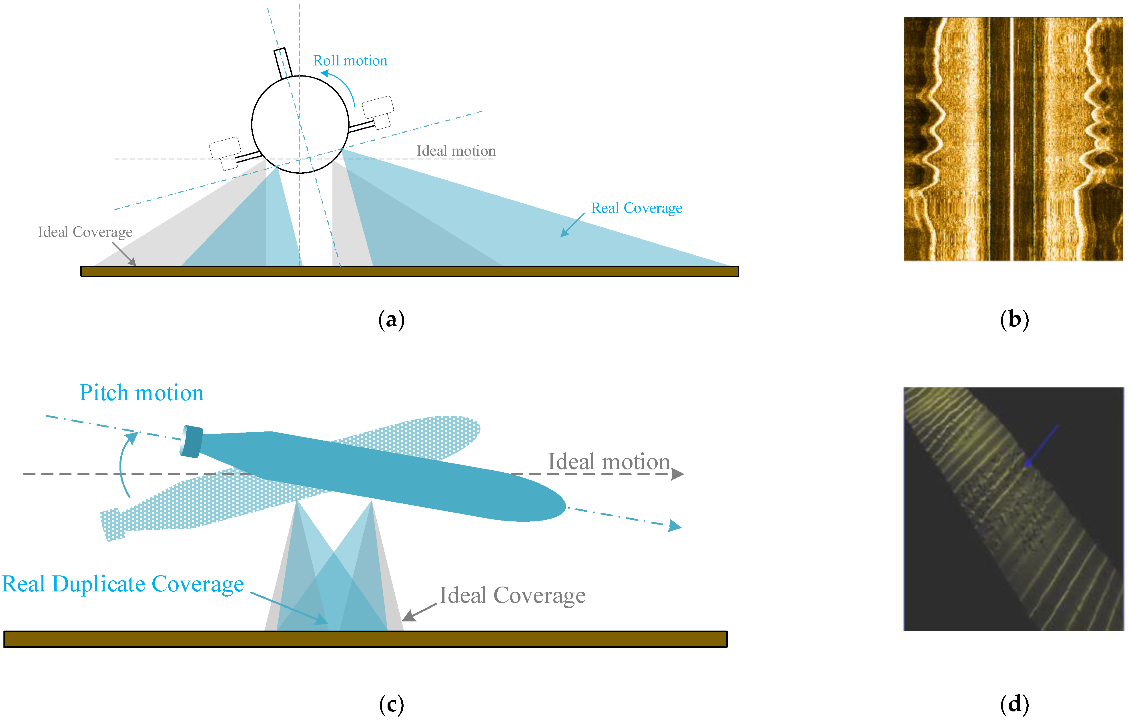
The transducer of Side Scan Sonar (SSS) emits a low incident-angle fan-sharp acoustic beam to seafloor along the shipping tracks, and the echo signal received from the seabed acoustic image chart [5]. The transducer’s acoustic beam-emission angle affects the image-chart quality. Furthermore, the angle depends on the attitude of the equipment equipped with SSS, and an unstable attitude may distort the images [6,7,8], as shown in Figure 1. Generally, the SSS is equipped on a towfish working underwater to avoid the interference of wind and waves, which is taken a rope by a scientific ship. A servo-actuated tail fin and an internal moving mass actuator are used to stable the longitudinal motion of a streamlined sensor platform [9]. Using large ships to survey and map is a time-consuming and laborious task. Autonomous Underwater Vehicle, the most popular intelligent equipment at present, plays an important role in seabed surveying and mapping, resource exploration, environmental monitoring, and national defense [10]. Therefore, it is a very common practice to use autonomous underwater vehicles to scan the ocean bottom.
According to the method of connection, underwater robots can be divided into cabled and cableless categories. A cabled underwater robot such as a Remote Operated Vehicle (ROV) can upload sensory data and video data to researchers in real time, but the detectable area is limited by the cable. In contrast, the endurance of a cableless underwater robot is related to the battery it carries. Furthermore, it automatically runs the predesigned workflow and can handle unexpected situations autonomously. A typical cable-free robot such as an underactuated AUV is generally composed of a forward propeller, a rudder, and an oil bladder [11]. It is difficult to maintain yaw and pitch angle only using the rudder for this kind of underwater robot when the forward speed is low. A quadrotor-like autonomous underwater vehicle is a new type of cableless underwater robot developed in recent years. The quadrotor-like autonomous underwater vehicle is similar to a quadrotor drone with thrusters as the actuator, so the AUV has the same flexible characteristics as an unmanned aerial vehicle. Therefore, due to the quadrotor-like AUV’s inherent advantages derived from its unique structure, it is a more suitable mobile platform for underwater topographic scanning.
Many scholars have conducted research on how to control AUV [12,13,14,15] in different ways. The most classic PID (Proportion–Integral–Differential) control algorithm has also been used in the attitude control of AUV [12]. To stabilize the attitude in both media, Chen et al. [13] developed a FUZZY P + ID controller that contains a FUZZY P (Proportion) item and normal ID (Integral–Differential) items for an aerial and underwater vehicle that can work both underwater and in the sky. The numerical simulations and experiments prove that the FUZZY P + ID controller has a better performance than the conventional PID controller in the complex nonlinear system. Due to the small and light quality of AUV, external interference has a great influence on its control strategy. The wave disturbance is estimated using unscented Kalman filter and a backstepping controller is established for an underwater vehicle [14]. To track the yaw angle under uncertainties and external disturbances, Kou et al. [15] designed a global fast terminal sliding mode control for AUV, which has a fast convergence rate compared to the linear sliding mode. Existing methods can effectively overcome external interference but are not sensitive to the performance of steady-state errors in control. Steady-state errors are mainly caused by thrust, such as a constant and unknown reaction torque generated by the forward propeller at a fixed speed, the change in thrust caused by the change of battery voltage under the condition of the same control signal, and so on. An effective method is to consider the dynamic model of the thruster [16,17].
As we know, Sliding Mode Control (SMC) is a robust, nonlinear control method that alters the dynamics of a nonlinear system by applying a discontinuous control signal. The effectiveness of SMC has been proven in tracking control problems in multiple domains [18,19]. Although it has the advantages of finite time-convergence and insensitivity to interference, its chattering phenomena and sensitivity to steady-state errors still exist. To improve the robustness of sliding mode control, we propose a novel attitude control method based on improved integral sliding mode, which can deal with steady state errors effectively [20].
This paper mainly solves the problem of maintaining AUV’s attitude stability for the usage of side scan sonar under steady-state error caused by model uncertainty and time-varying external interference. Firstly, based on the previous design of AUV [21], a high maneuverable version AUV with seven propellers is designed to complete several actions such as fixed-point lifting, pivot steering, lateral movement, etc. Secondly, due to the side scan sonar needs to maintain the posture level during operation, the dynamic model for attitude control of AUV is given in detail. Furthermore, the sliding surface for motion control and the attitude control law are developed, which can reduce the static attitude bias caused by mechanical structure and overcome the external disturbances. Finally, the proposed control strategy is validated with simulations as well as engineering applications, and the results show that the proposed IISMC-based attitude-control method is robust for external interference and uncertainty. Compared with the previous research, the main contributions of this work are summarized as follows:
- (1)
- A Gaussian function is introduced into the integral sliding-mode control to reduce the over-reaction of the integral term caused by strong disturbances, while eliminating the steady-state error caused by system uncertainty and external disturbance and enhance the system robustness.
- (2)
- The attitude-control laws are designed based on the improved integral sliding mode and its convergence is proved by employing Lyapunov theory. Moreover, the practical experiments confirm the simulation results.
The remainder of this paper is organized as follows: in Section 2, the mechatronic design and dynamic modeling of quadrotor-like AUV are provided. The attitude-control method based on sliding mode is designed and its stability is proved in Section 3. The numerical simulations and engineering validation results of the proposed attitude-control method are exhibited in Section 4, and finally the conclusion is given in Section 5.
2. Autonomous Underwater Vehicle Design and System Modeling
In this section, the mechanical structure of AUV is introduced. Then, based on the mechanical system, the electronic system is conducted. Finally, the dynamic modeling of high maneuverable AUV is established.
2.1. Mechatronic Design
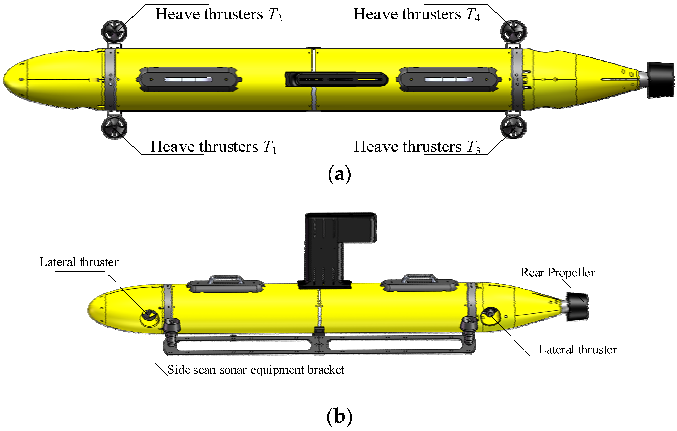
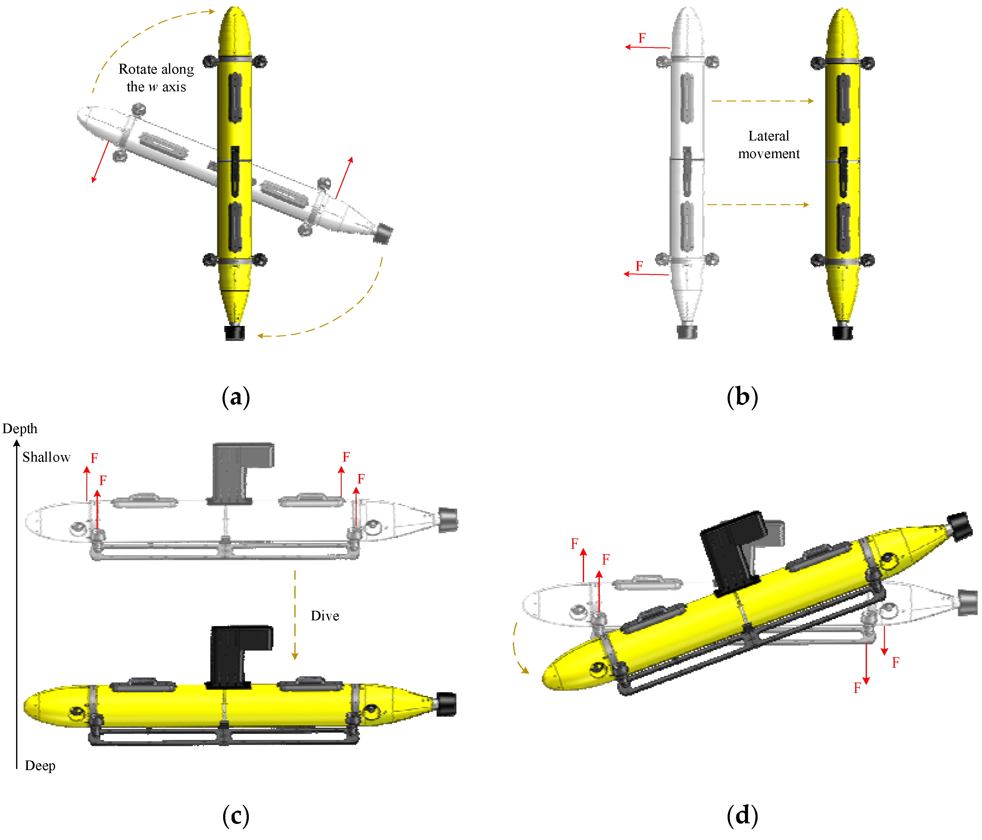
Since it is difficult for traditional AUV to complete operations in complex environments, such as narrow spaces, sharp bends, strong current interference, etc., a highly maneuverable AUV with seven propellers is designed which can complete full-freedom actions such as fixed-point lifting, pivot steering, lateral movement, etc. The mechanical structure of AUV is described in Figure 2, which consists of four heave thrusters, two lateral thrusters, one rear propeller, and a side-scan sonar equipment bracket. A propeller at the rear of AUV provides forward force. The front and rear thrusters are steering modules that apply force on the vehicle to change the heading angle. The movement, attitude, and heading are controlled by the assembled seven thrusters in different directions and positions. It is worth noting that the attitude and depth-control module are composed of four heave thrusters distributed in the robotic body. By adjusting the rotation speed of the four propellers to generate different forces, the designed AUV can be floated and submerged as well as its attitude control. These thrusters and propeller are brushless DC motors, driven by Electronic Speed Controls. In addition, the designed AUV is also equipped with inertial navigation, GPS, DVL, and water-pressure sensors to measure its own motion performance. To summarize, the proposed highly maneuverable AUV can finish different kinds of task actions in Figure 3.
The notations in the dynamic model are summarized in Table 1.
2.2. Dynamic Modeling
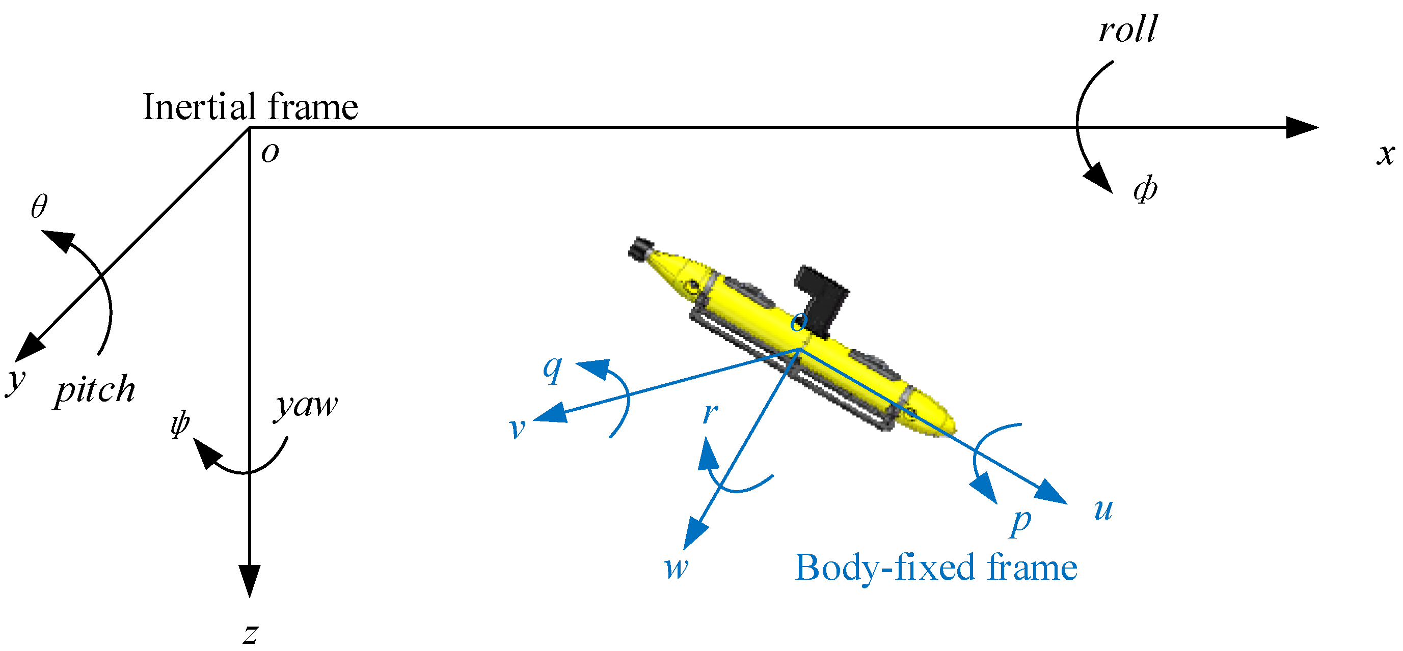
Aiming at attitude-control system for the proposed AUV, a kinematic model is established. The inertial frame and body-fixed frame are introduced to describe the state of AUV, as Figure 4. In the body-fixed frame, p and q denote the angular velocities of AUV on the u-axis and v-axis. ϕ and θ denote the attitude of AUV in the inertial frame. Since only the attitude is considered in this paper, the complete kinematic equations [22] can be simplified as:
The attitude dynamics model of AUV in the body-fixed frame is simplified from the full model in [22] and divided into two subsystems, generically described as:
where Ix and Iy are the moments of inertia, d1 and d2 denote the linear damping efforts, zg is the distance between the center of gravity and geometric, m is the mass of AUV, and g is gravitational acceleration. The parameters τpd and τqd are lumped system uncertainties including system model estimation error and external disturbances, respectively. Considering that wind and wave disturbances are bounded in most cases, the following assumptions are given.
Assumption 1:
The system model estimation error and time-varying external disturbances are bounded, i.e., Max(||τpd||, ||τqd||) < Tm, where Tm is upper bound of external interference.
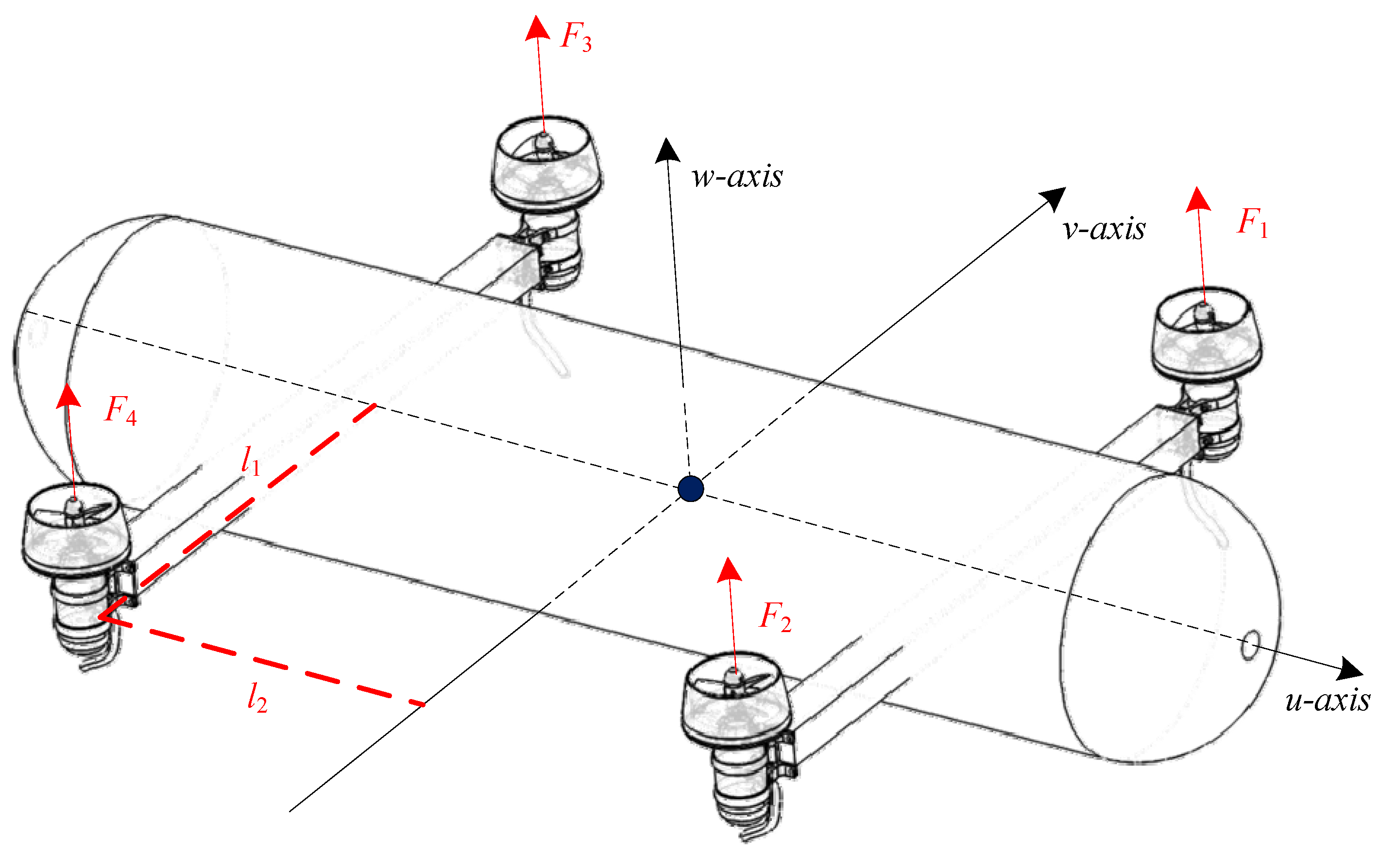
Figure 5 illustrates the symmetrical arrangement of heave thrusters around the well-designed AUV, where l1 and l2 denote distance from the thrusters to the u-axis and v-axis. F1, F2, F3, and F4 denote the forces of four heave thrusters T1, T2, T3, and T4. The τp and τq denote the moments synthesized by four heave thrusters in the two directions, which can be described as follows.
Four heave thrusters can control the pitch, roll, and depth of AUV through combined actions; the depth control is not studied in this work. To ensure that the depth will not be changed by the movement of four thrusters, it means that the resultant force of four thrusts on the w-axis is zero. Hence, there is the following assumption.
Assumption 2:
The thrust force F1 is equal to negative F4 and F2 is equal to negative F3.
Following Assumption 2, the thrust-mapping strategy of each thruster can be expressed as Equation (4) when the input moments τp and τq are given by the attitude controller.
Considering that the thrust force of the actual thruster is limited, the upper and lower bounds of the thrust are limited according to the real performance of the thruster model.
3. Attitude-Control Law Based on IISMC
3.1. Integral Sliding Mode Control
ISMC [20] has been widely employed in many scopes, such as robotic control, electric drives, etc. Compared with conventional SMC, ISMC has a better ability to start sliding mode at the initial time and eliminate the steady-state error of the whole system, besides its fast response and anti-interference ability. The sliding mode surface S can be designed as:
where S0(x) is similar to conventional sliding mode and parameter z is the integral item. The initial z(0) can be designed as −S0(x(0)) to ensure S = 0 at initial time. Generally, the ISMC surface can be designed as follows,
where x and are the tracking error and tracking velocity error; sliding mode coefficients α1 and α2 are two positive constants.
It can be seen from the equation that the sliding mode surface will be zero only when x, , and the integral term converge to zero, i.e., S = 0. The integral term is the accumulation of error x, and its convergence means that cumulative positive error equals negative error. Therefore, after a big error occurs, an equal amount of reverse error is required to achieve convergence. To solve this problem, we introduce a Gaussian function to scale the error in the integral term to make the integral term converge faster. The designed surface of improved ISMC (IISMC) is defined as:
where x, α1 and α2 are defined the same as Equation (7), and γ is a positive constant that represents an integral term attenuation factor. If the γ decreases, the integral term z is less affected by the error x.
Remark 1.
The initial integral term in IISMC is 0, not −S0(x(0)). The reason is that the Gaussian function reduces the component of x in . The larger the absolute value of x, the closer the Gaussian function is to zero, so will also be smaller, resulting in a very slow change of z. Hence, if the initial value z(0) is −S0(x(0)), the integral term z cannot reach zero in a finite time.
3.2. Attitude-Control Algorithm Design
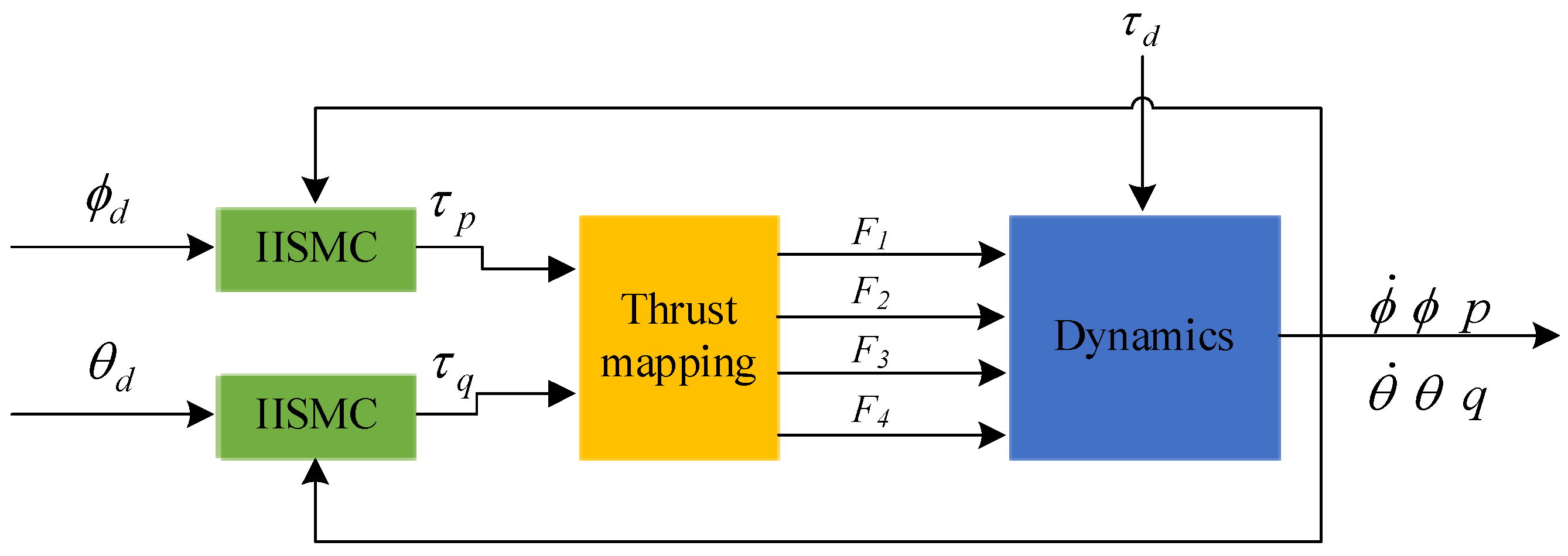
In this section, we propose an IISMC-based attitude-control method to address the previous problem. The block diagram of the IISMC-based attitude-control scheme is demonstrated in Figure 6.
According to the Gaussian ISMC surface designed in Equation (8), the attitude-control sliding mode surface for θ and ϕ is defined as:
where γ1, γ2, α1, α2, α3, and α4 are positive constants, and the attitude-tracking error ϕe and θe in the inertial frame can be denoted as:
where and are the desired attitude angles of the well-designed AUV, respectively. Then, the angular velocity errors are defined as:
where and denote the desired angles velocity.
Consider the attitude-tracking error dynamics with θ and ϕ sliding-mode surface function (9) and (10); the control laws are designed as:
where
where
where τp3 and τq3 are switching terms; εϕ and εθ are positive constants, respectively. The function sgn(S) is defined as:
3.3. Stability Analysis
Theorem 1.
When this system adoptsEquations (13) and (16) control law for attitude control and satisfiesAssumptions 1, the tracking error of quadrotor-likeAUV can converge to zero.
Proof of Theorem 1.
Select the following Lyapunov function,
Deriving V, (9), (10), (11), (12), and (2) are substituted into
Substituting Assumption1 and control law Equation (13), (16) into (21), the Lyapunov function can be expressed as:
According Lyapunov theory, εϕ and εθ need to meet the following conditions, and the integral sliding-mode surfaces Sθ and Sϕ mentioned in Equations (9) and (10) will converge to zero.
□
Remark 2.
Ix and Iy are nonzero moment of inertia of the AUV. The coefficient a1 and a3 are also nonzero constant. Therefore, εϕ and εθ exist and are bounded positive constants.
In order to eliminate the chattering that could damage the actuators of the AUV in engineering practice, the saturation function sat() is used instead of the function sgn() to suppress the chattering phenomenon [23], which can be written as:
where δ is a positive constant and represents the thickness of boundary layer.
4. Simulation and Field Experiments
4.1. Simulation Step
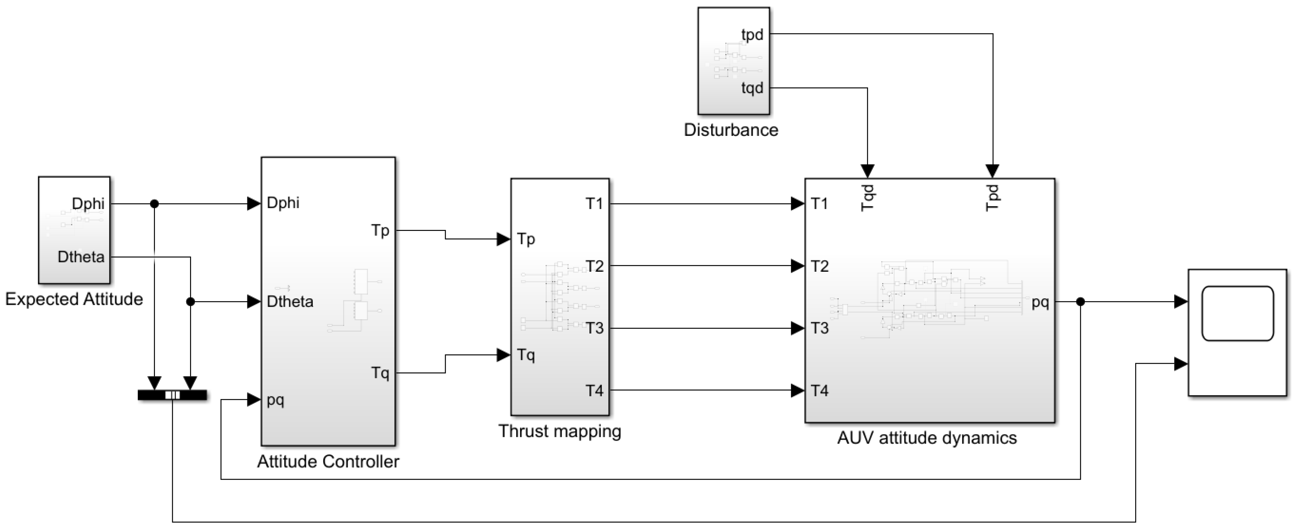
The verifications of attitude-control methods based on improved integral sliding mode are introduced in this section. Numerical validation is carried out using Simulink module using MATLAB R2020b, as shown in Figure 7. In order to verify the performance of our proposed algorithm, three different control methods such as SMC-, ISMC-, and PID-based attitude-control algorithms are given in Table 2 and the controller parameters are given in Table 3 in detail. Two expected attitudes and two disturbances are used to simulate the real environment.
The key parameters of the quadrotor-like AUV model obtained by fitting many experiments are listed in Table 4.
To verify the performance of controllers in simulation, two kinds of disturbances are used to simulate the real environment. One is steady-state disturbance caused by the reaction torque of the forward propeller, and the other is the external disturbance that simulates the external wind and waves, including sinusoidal function, random disturbance and steady-state disturbance. In addition, the attitude-tracking performance of the designed controller is also verified. Four experimental scenarios are listed in Table 5.
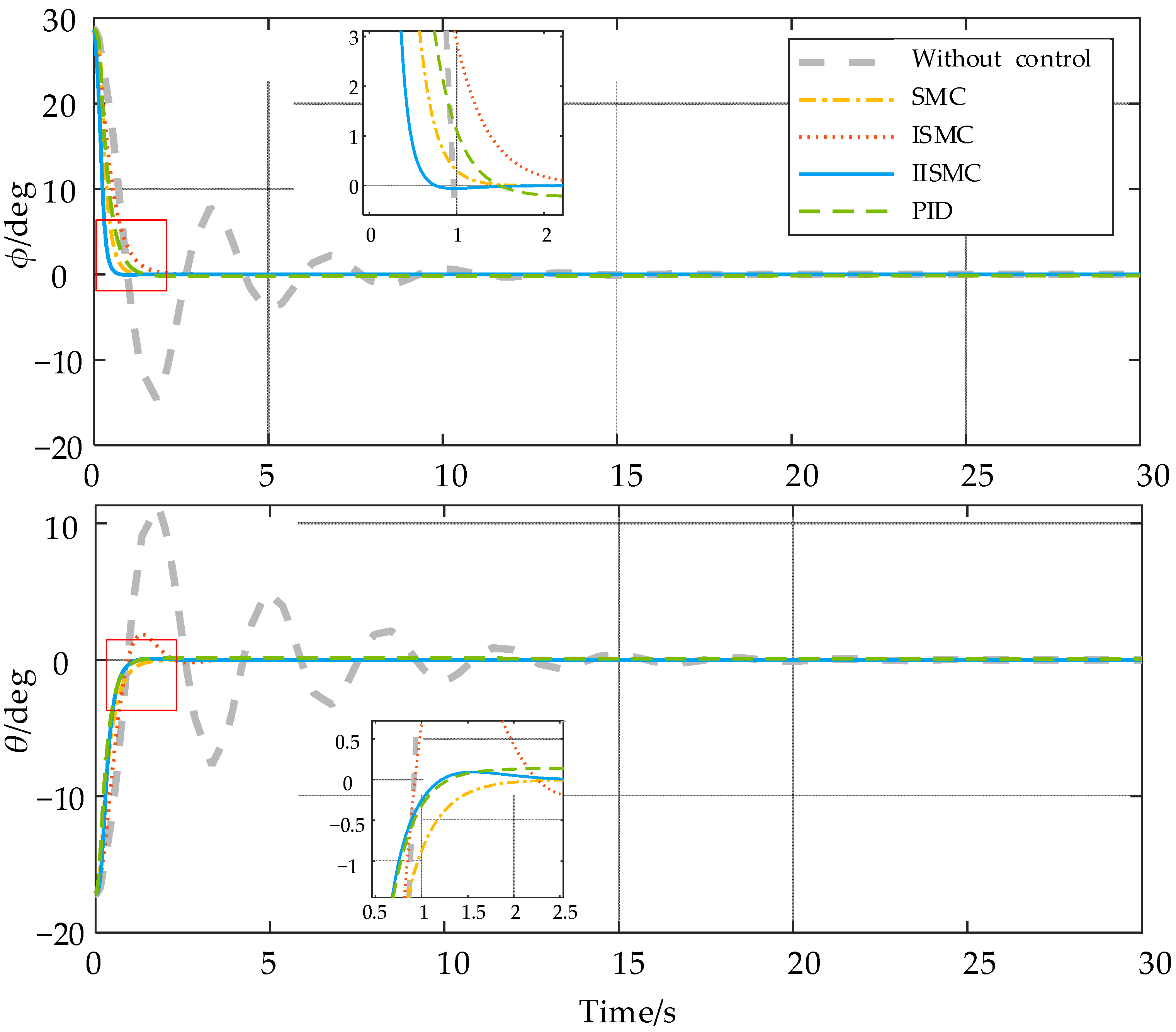
In Scene 1, four attitude-control methods are compared in the interference-free environment. The initial attitude angle ϕ and θ of the high maneuverable AUV are 0.5 and −0.3 rad, and the desired attitude angles ϕd and θd are 0. In the case of no control—that is, τp and τq are zero—it can be seen from the thick gray dashed line that it takes tens of seconds to stabilize in Figure 8. In contrast, attitude angles under four control methods can quickly approach zero. Figure 9 shows the thrust curves of four heave thrusters, and there are some glitches in the blue thin dashed line under PID control, while other curves are much more stable. The reason for the glitch lies in the differential term in the PID controller.
In Scene 2, the steady-state disturbance is added; all four attitude-control methods can keep the attitude stable in Figure 10, however, and there are still some errors in the orange dashed/dotted line. This is caused by steady-state errors that cannot be eliminated by SMC. Figure 11 is the cumulative error curve of absolute ϕe and θe under different methods. The cumulative error of SMC and PID are always rising. In contrast, the cumulative error of ISMC and IISMC will rise rapidly at the beginning of the simulation due to the nonzero initial attitude, and then gradually stabilize. Compared to the thrusters thrust in Scenario 1, the thrust glitch of PID method in Figure 12 are much smaller, and the ISMC and IISMXC are still very stable. This shows that the ISMC and IISMC have better performance to suppress steady-state errors.
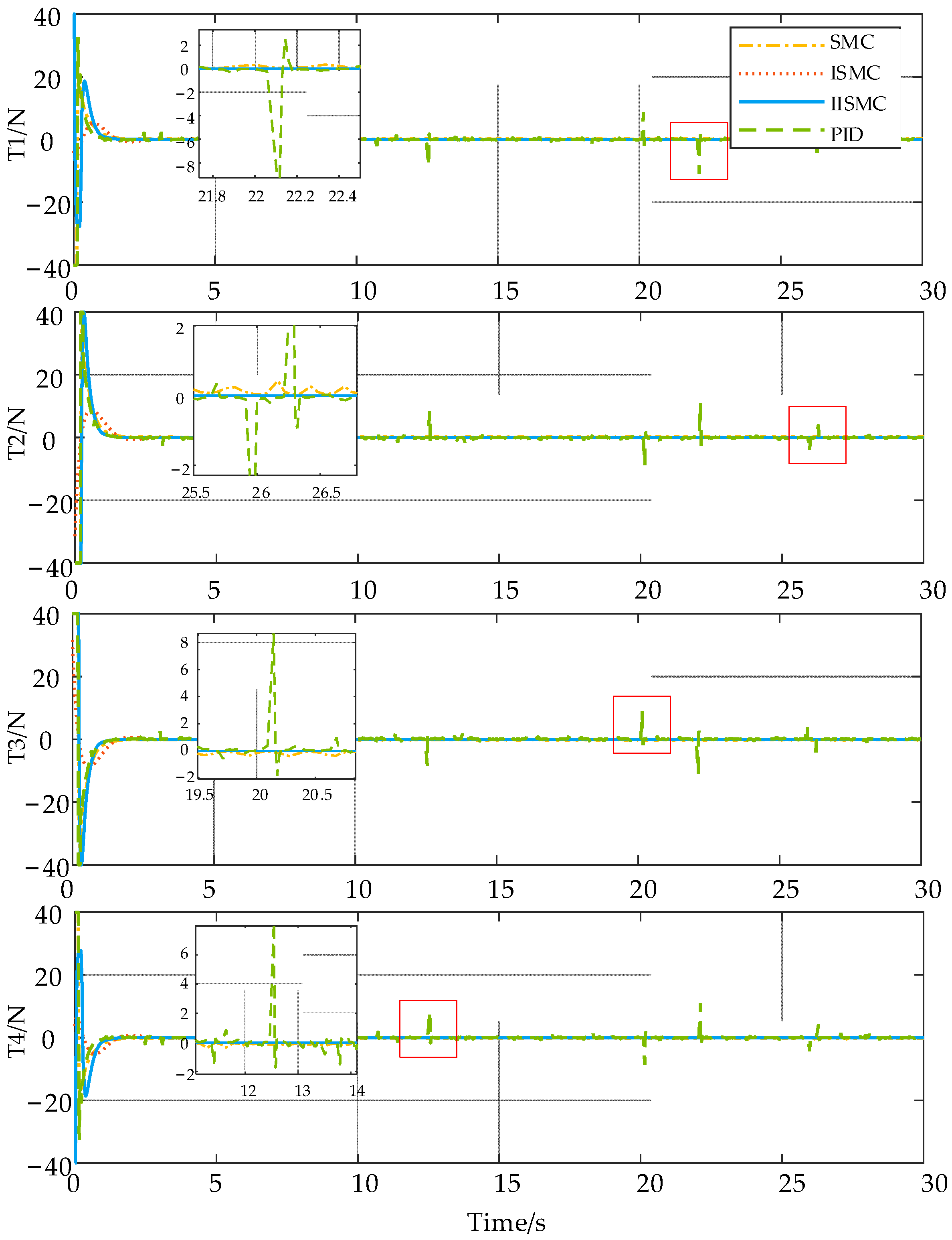
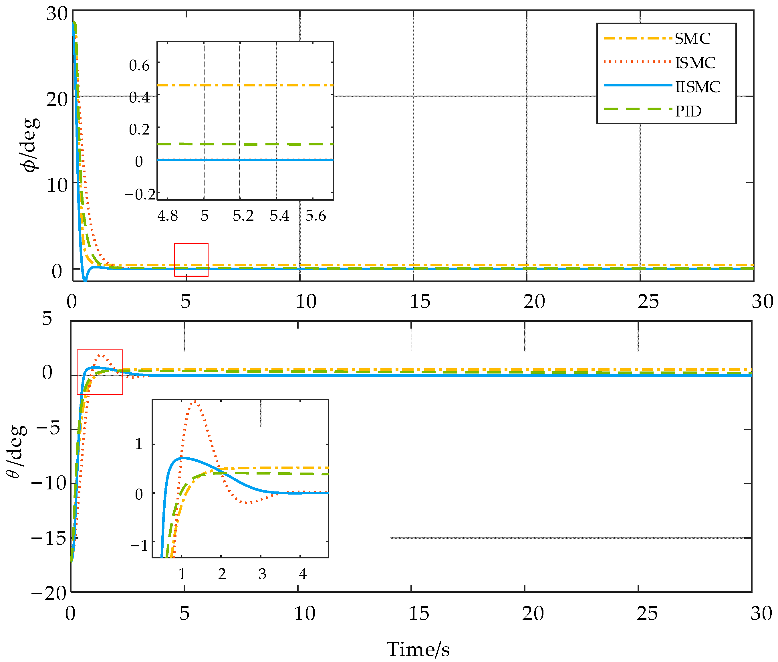
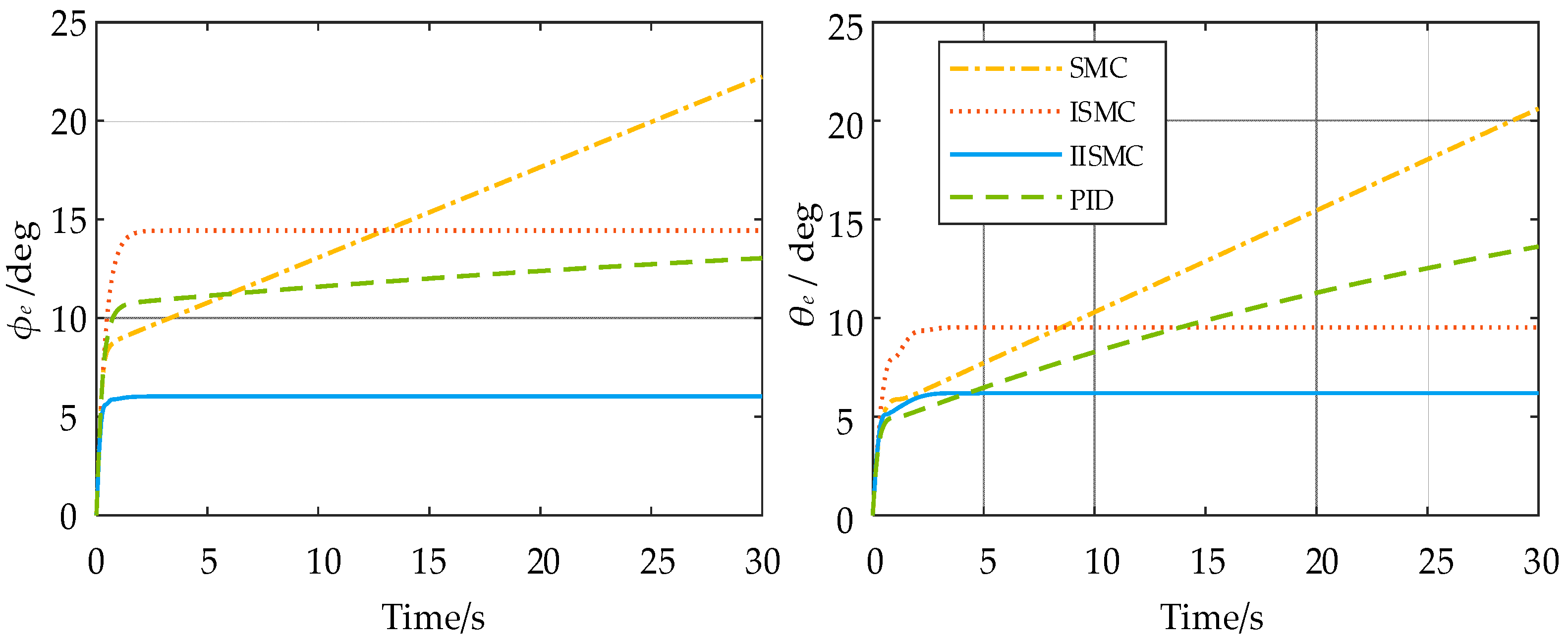
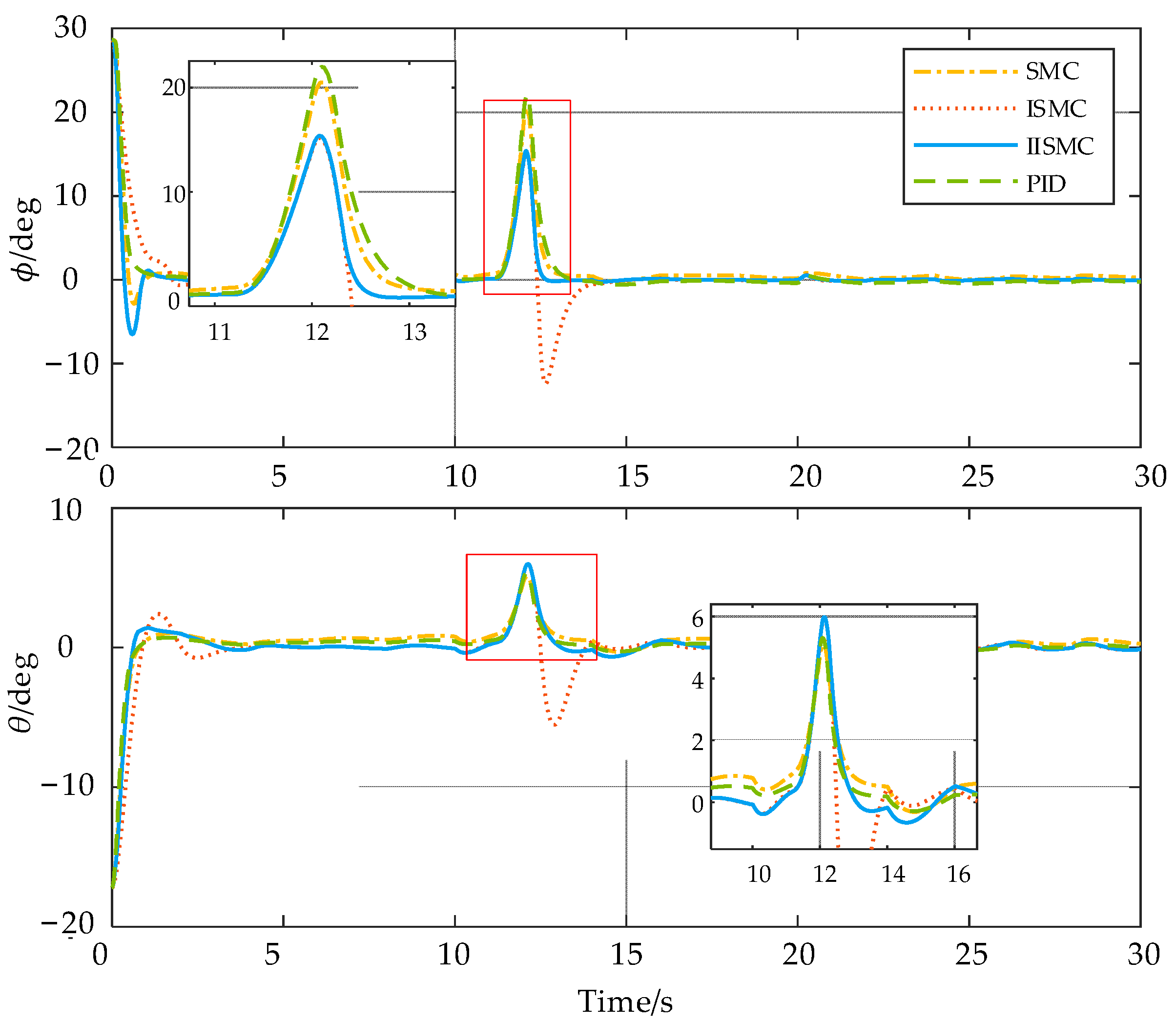
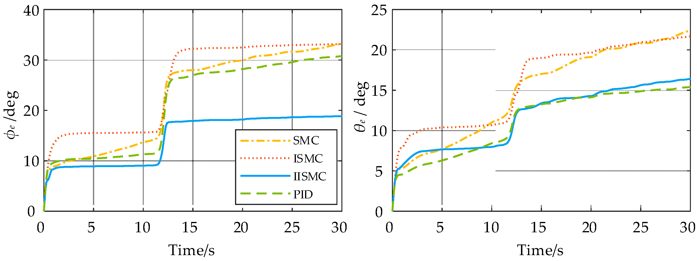
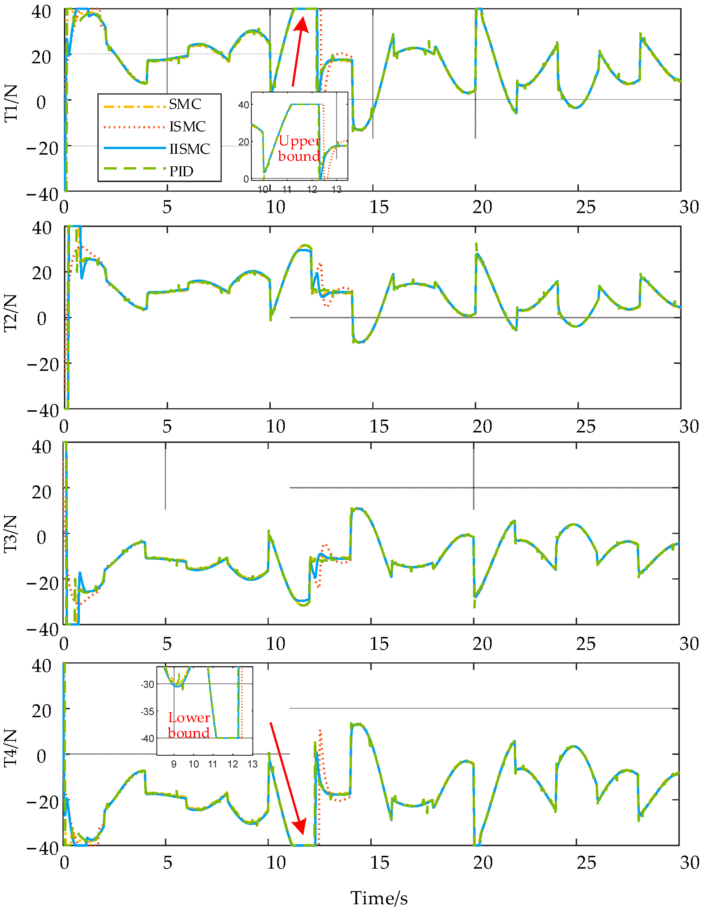
On the basis of steady-state interference, random noise and sinusoidal interference are added to simulate the wind and wave environment in Scene 3. All the methods in Figure 13 have obvious overshooting at 12 s in both attitude angles ϕ and θ. This causes a sharp increase in error in Figure 14. The reason is the thrusters T1 and T4 reach the upper and lower bounds and cannot effectively overcome the interference in Figure 15. However, after the overshooting, the red dotted ISMC cannot reach the expected attitude immediately like other methods. The reason is when the sliding surface is at zero, the integral term of ISMC must be zero, and then the positive error plus the negative error is zero. Hence, to compensate for positive error, the negative error occurs at 13 s. In contrast, since SMC-based attitude-control has no integral term, the attitude angles will quickly stabilize, but there is also a certain steady-state error that cannot be eliminated. The Gaussian function is added to attenuate the error of integral term in IISM, and strong disturbances have little effect on the integral term, so the negative errors are smaller. In Figure 14, the proposed IISMC algorithm performs well compared to the other three attitude-control algorithms.
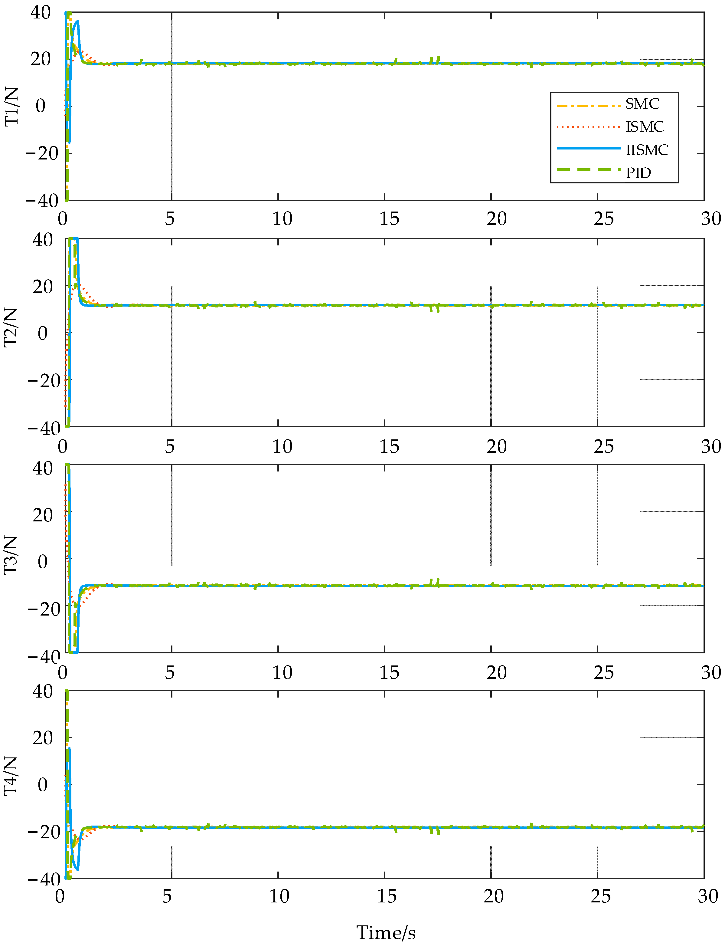
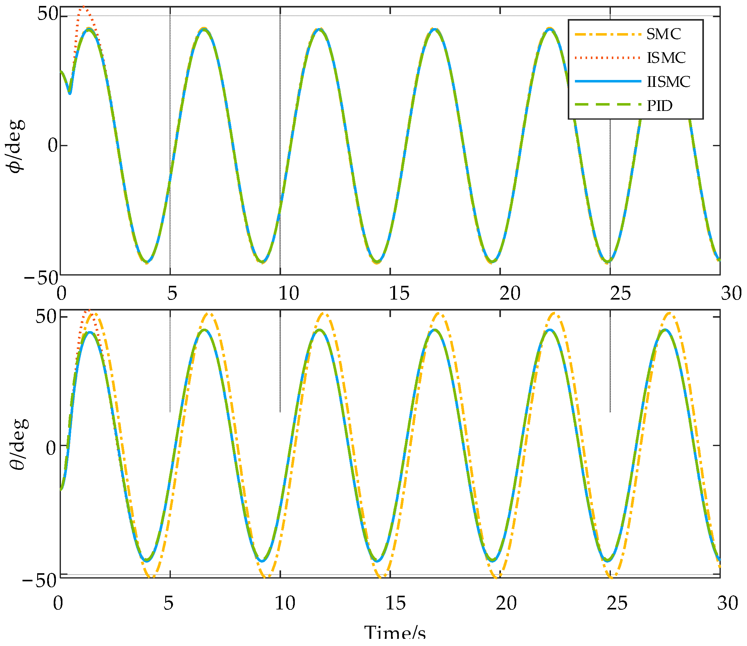
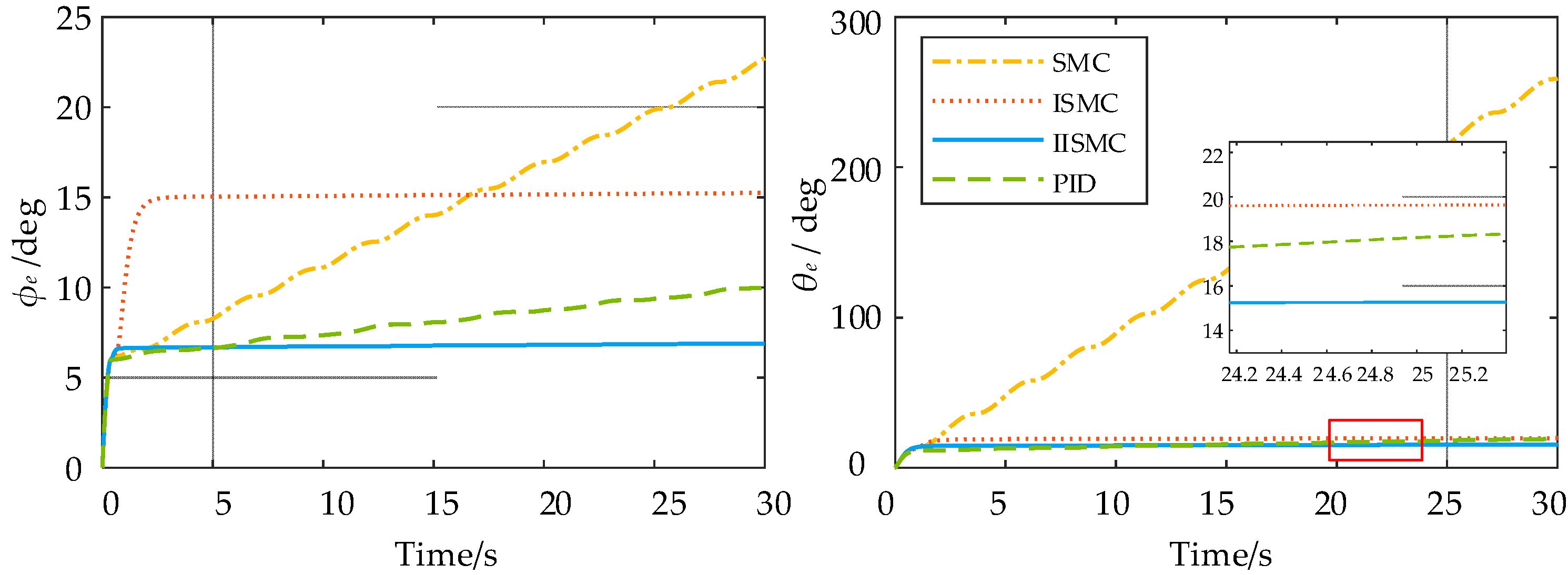
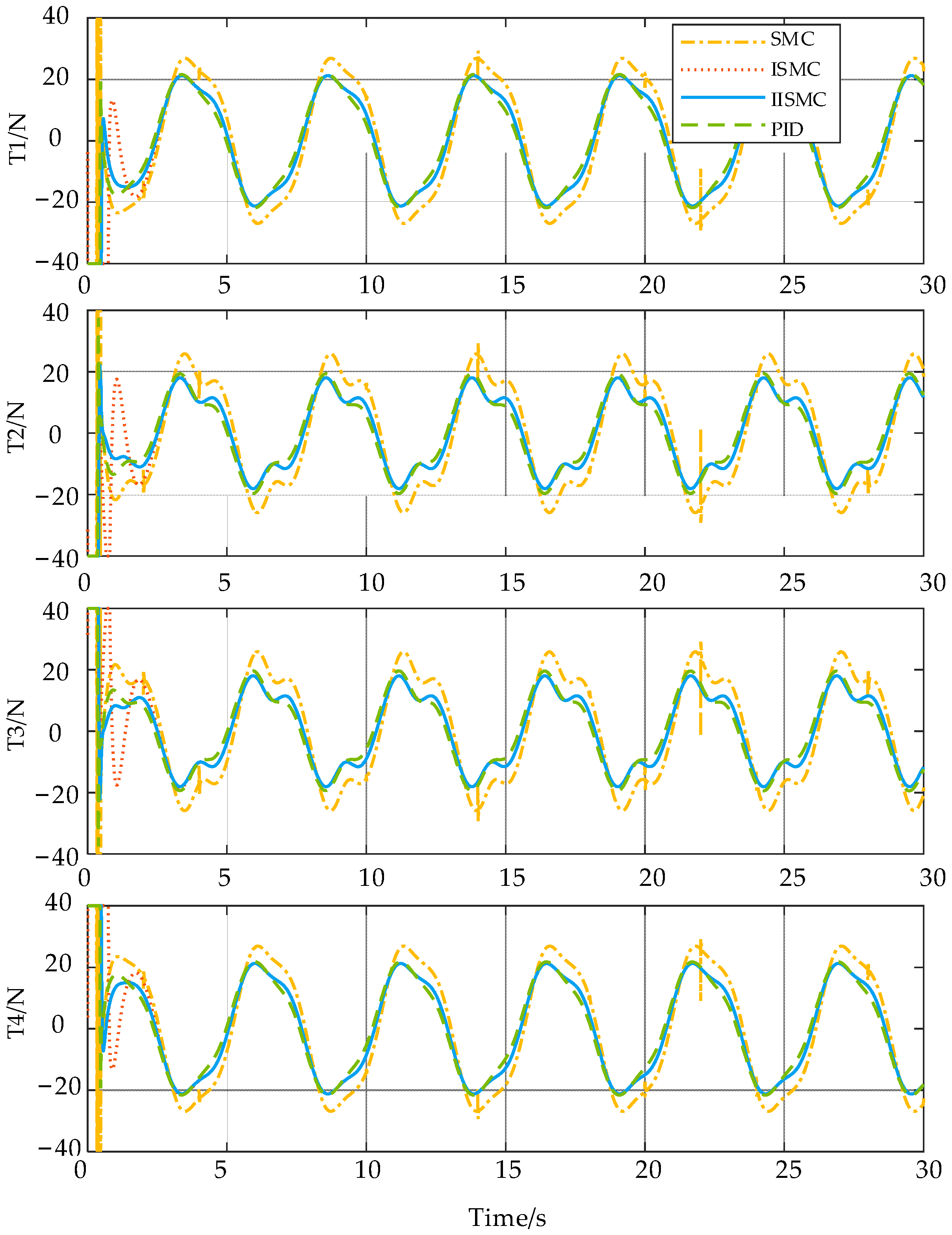
The attitude-tracking performance is tested with Scene 4. The designed attitude angles ϕd and θd are 45 × sin7.5t. It can be seen from Figure 16 that the tracking performance of SMC is slightly worse than other methods, especially for the θ angle. Figure 17 illustrates that the blue solid line is the smallest one and has better stability. The thrust force curve of SMC is significantly different from other methods in Figure 18.
In conclusion, it can be concluded that the IISMC-based attitude-control method can quickly reach the specified attitude under different interference conditions; moreover, it has better stability than other three control methods.
4.2. Field Experiments
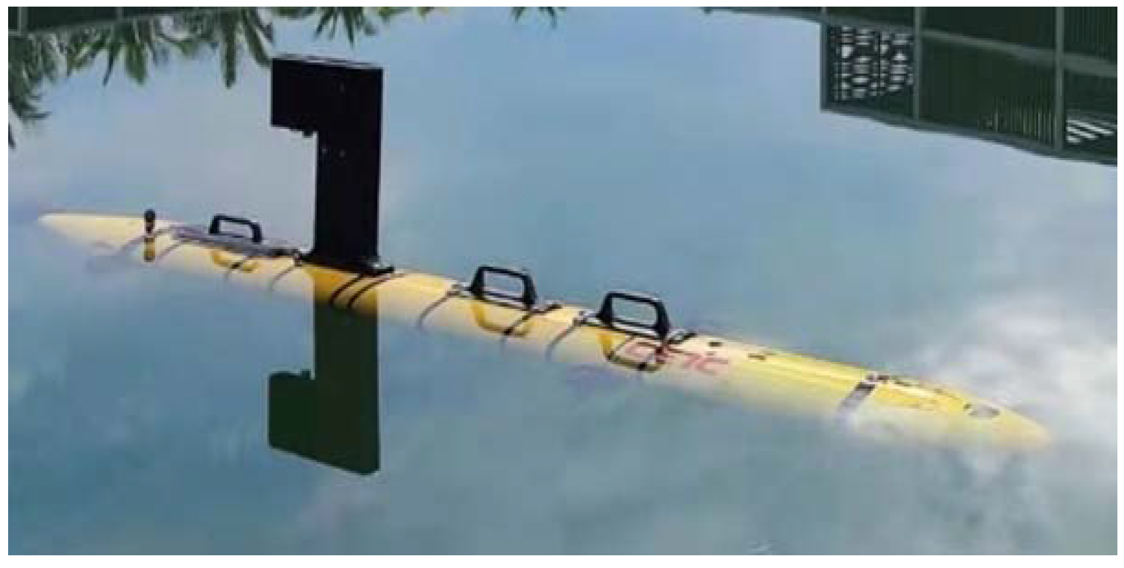
This filed test is carried out in a static rectangular pool as Figure 19. The previous PID- and IISMC-based attitude-control methods are compared in the pool.
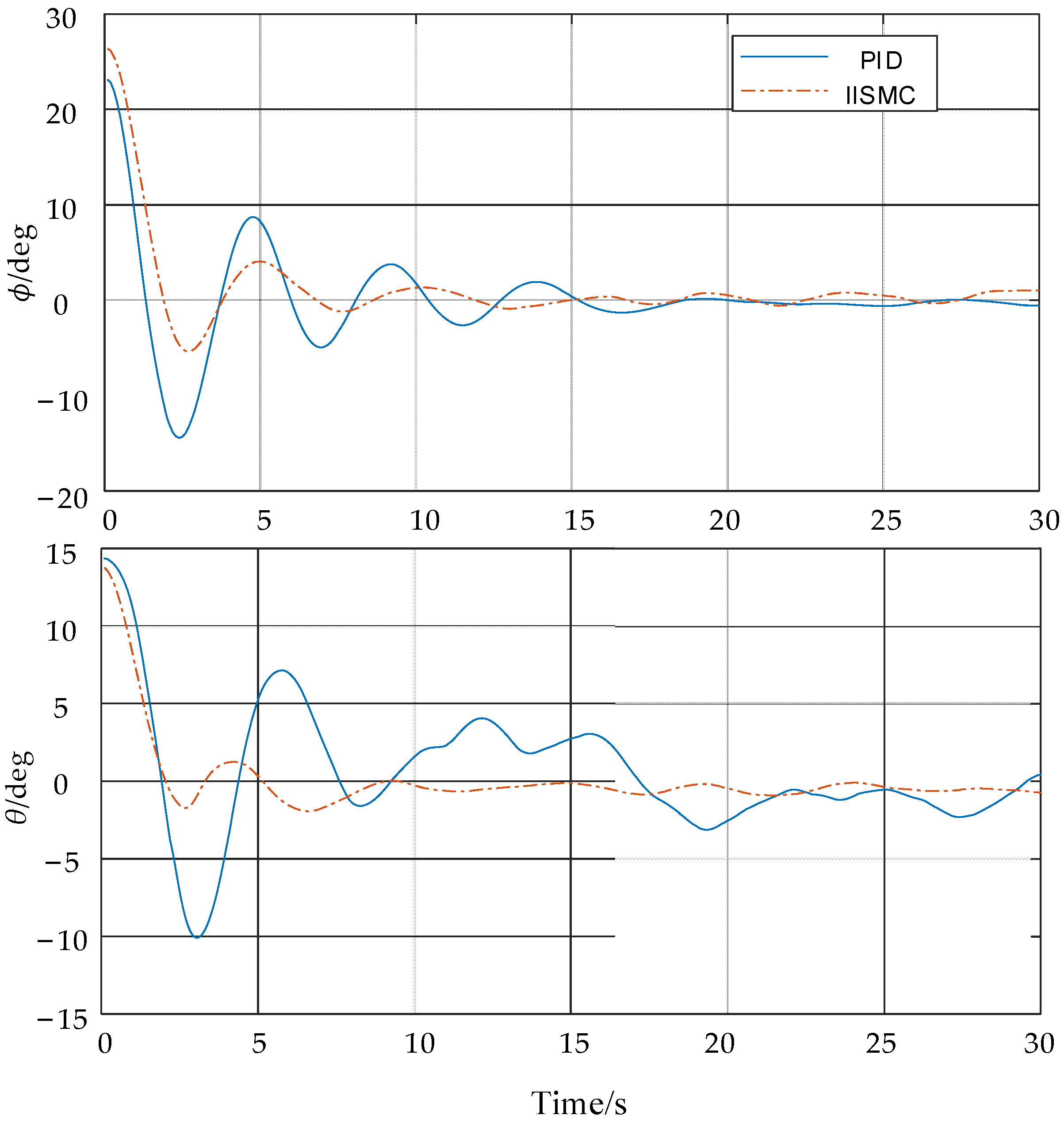
The initial attitude angle is adjusted to about 25 degrees and 15 degrees by external force. The angles of well-designed AUV will gradually approach zero after the external force stops. It is obvious from Figure 20 that the attitude effect of the IISMC-based method can converge faster than the original PID-based attitude-control method.
5. Conclusions
This paper focuses on IISMC-based attitude-control method for high maneuverable AUV adjusting its body’s attitude with four heave thrusters. A novel integral sliding mode is used as the controller to improve the robustness of the control system, and the Gaussian function is introduced into the controller to reduce the interference of the integral term. The conditions for the stability of the control system are obtained using the Lyapunov function; numerical simulation and field experiments verify the effectiveness and better robustness of the proposed algorithm. Compared with three existing approaches, the proposed IISMC-based controller has a faster convergence speed than ISMC when subjected to strong disturbances and can effectively overcome the steady-state tracking error. In the actual underwater environment, the response of the thruster lags, and the response of the same thrusters is also different under the same driving signal. For future work, we believe that deep reinforcement learning can be used to train AUV autonomous-learning-control strategies to overcome the problems above.
Author Contributions
Conceptualization, Z.L. and W.C.; methodology, Z.L. and W.C.; software, Z.L. and W.C.; validation, Z.L., W.C. and S.L.; formal analysis, Z.L., W.C., M.Z. and S.L.; investigation, Z.L., W.C., M.Z. and S.L.; resources, Z.L., W.C., M.Z. and S.L.; data curation, Z.L., W.C., M.Z. and S.L.; writing—original draft preparation, Z.L., W.C., M.Z. and S.L.; writing—review and editing, Z.L., W.C. and M.Z.; visualization, Z.L. and W.C.; supervision, W.C. and M.Z.; project administration, W.C.; funding acquisition, W.C., M.Z. and S.L. All authors have read and agreed to the published version of the manuscript.
Funding
This research has been partially supported by Natural Science Foundation of Zhejiang Province (No. LZ22F010004 and LZJWY22E090001), Fundamental Research Funds for the Provincial Universities of Zhejiang (No. GK209907299001-001), National Natural Science Foundation of China (No. 61871163 and No. 61801431) and the Stable Supporting Fund of Acoustics Science and Technology Laboratory.
Institutional Review Board Statement
Not applicable.
Informed Consent Statement
Not applicable.
Data Availability Statement
Not applicable.
Acknowledgments
The authors would like to thank the anonymous referees for their constructive comments and valuable suggestions, which helped us to greatly improve the quality and presentation of the paper.
Conflicts of Interest
The authors declare no conflict of interest.
References
- Shih, C.C.; Horng, M.F.; Tseng, Y.R.; Su, C.F.; Chen, C.Y. An Adaptive Bottom Tracking Algorithm for Side-Scan Sonar Seabed Mapping. In Proceedings of the IEEE Underwater Technology (UT) Conference, Kaohsiung, Taiwan, 16–19 April 2019. [Google Scholar]
- Fissel, D.B.; Chave, R.A.J.; Clarke, M.; Johnston, P.; Borg, K.; Marko, J.R.; Ross, E.; Buermans, J.; Stone, M. Advances in moored upward looking sonar systems for long term measurement of arctic ice and oceanography. In Proceedings of the 2013 OCEANS, San Diego, CA, USA, 23–27 September 2013; pp. 1–7. [Google Scholar]
- Ye, Y.; Lai, X.; Pan, G.; Li, Q.; Zhuang, Z.; Liu, D.; Chen, X.; Wei, Y.; Chen, j.; Hu, T.; et al. Chapter 8-Local Scour and Protection of Marine Structures. In Marine Geo-Hazards in China; Elsevier: Amsterdam, The Netherlands, 2017; pp. 297–366. [Google Scholar]
- McRea, J.E.; Greene, H.G.; O’Connell, V.M.; Wakefield, W.W. Mapping marine habitats with high resolution sidescan sonar. Oceanol. Acta 1999, 22, 679–686. [Google Scholar] [CrossRef] [Green Version]
- Ye, Y.; Lai, X.; Pan, G.; Li, Q.; Zhuang, Z.; Liu, D.; Chen, X.; Wei, Y.; Chen, j.; Hu, T.; et al. Chapter 11-Submarine Shallow Natural Gas. In Marine Geo-Hazards in China; Elsevier: Amsterdam, The Netherlands, 2017; pp. 453–521. [Google Scholar]
- Preston, J.M.; Poeckert, R. Distortion and break-up of sidescan images-criteria and reconstruction by geocoding. In Proceedings of the Oceans 93-Engineering in Harmony with the Ocean, Victoria, BC, Canada, 18–21 October 1993; pp. A371–A377. [Google Scholar]
- Preston, J.M. Stability of Towfish Used As Sonar Platforms. In Proceedings of the Conf on Mastering the Oceans through Technology (Oceans 92), Newport, RI, USA, 26–29 October 1992; pp. 888–893. [Google Scholar]
- Chen, E.; Guo, J.H. Real time map generation using sidescan sonar scanlines for unmanned underwater vehicles. Ocean. Eng. 2014, 91, 252–262. [Google Scholar] [CrossRef]
- Woolsey, C.A.; Gargett, A.E. Passive and active attitude stabilization for a tow-fish. In Proceedings of the 41st IEEE Conference on Decision and Control, Las Vegas, NV, USA, 10–13 December 2002; pp. 2099–2104. [Google Scholar]
- Vidal, E.; Hernandez, J.D.; Palorneras, N.; Carreras, M. Online Robotic Exploration for Autonomous Underwater Vehicles in Unstructured Environments. In Proceedings of the OCEANS-MTS/IEEE Kobe Techno-Oceans Conference (OTO), Kobe, Japan, 28–31 May 2018. [Google Scholar]
- Huang, Y.; Qiao, J.N.; Yu, J.C.; Wang, Z.Y.; Xie, Z.B.; Liu, K. Sea-Whale 2000: A Long-range Hybrid Autonomous Underwater Vehicle for Ocean Observation. In Proceedings of the OCEANS-Marseille Conference, Marseille, France, 17–20 June 2019. [Google Scholar]
- Ranganathan, T.; Thondiyath, A.; Kumar, S.P.S. Design and Analysis of an Underwater Quadrotor-AQUAD. In Proceedings of the 2015 IEEE Underwater Technology (UT), Chennai, India, 23–25 February 2015. [Google Scholar]
- Chen, Q.; Zhu, D.Q.; Liu, Z.B. Attitude control of aerial and underwater vehicles using single-input FUZZY P+ID controller. Appl. Ocean. Res. 2021, 107, 102460. [Google Scholar] [CrossRef]
- Ohhira, T.; Kawamura, A.; Shimada, A.; Murakami, T. An Underwater Quadrotor Control with Wave-disturbance Compensation by a UKF. In Proceedings of the 21st IFAC World Congress on Automatic Control-Meeting Societal Challenges, Berlin, Germany, 11–17 July 2020; pp. 9017–9022. [Google Scholar]
- Kou, L.; Xiang, J.; Li, Y.; Bian, J. Yaw Angle Tracking Control for a Quadrotor-Like Autonomous Underwater Vehicle Using Global Fast Terminal Sliding Mode Control. In Proceedings of the 2018 IEEE 8th Annual International Conference on CYBER Technology in Automation, Control, and Intelligent Systems (CYBER), Tianjin, China, 19–23 July 2018; pp. 827–832. [Google Scholar]
- Yoerger, D.R.; Cooke, J.G.; Slotine, J.J.E. The influence of thruster dynamics on underwater vehicle behavior and their incorporation into control system design. IEEE J. Ocean. Eng. 1990, 15, 167–178. [Google Scholar] [CrossRef] [Green Version]
- Di Vito, D.; Cataldi, E.; Di Lillo, P.; Antonelli, G. Vehicle adaptive control for underwater intervention including thrusters dynamics. In Proceedings of the 2nd IEEE Conference on Control Technology and Applications (CCTA), Copenhagen, Denmark, 21–24 August 2018; pp. 646–651. [Google Scholar]
- Sun, G.H.; Ma, Z.Q.; Yu, J.Y. Discrete-Time Fractional Order Terminal Sliding Mode Tracking Control for Linear Motor. IEEE Trans. Ind. Electron. 2018, 65, 3386–3394. [Google Scholar] [CrossRef]
- Dhanasekar, R.; Kumar, S.G.; Rivera, M. Sliding Mode Control of Electric Drives/Review. In Proceedings of the IEEE International Conference on Automatica (ICA-ACCA), Curico, Chile, 19–21 October 2016. [Google Scholar]
- Utkin, V.; Shi, J.X. Integral sliding mode in systems operating under uncertainty conditions. In Proceedings of the 35th IEEE Conference on Decision and Control, Kobe, Japan, 11–13 December 1996; pp. 4591–4596. [Google Scholar]
- Wang, C.; Cai, W.; Lu, J.; Ding, X.; Yang, J. Design, Modeling, Control, and Experiments for Multiple AUVs Formation. IEEE Trans. Autom. Sci. Eng. 2021, 1–12. [Google Scholar] [CrossRef]
- Fossen, T.I. Handbook of Marine Craft Hydrodynamics and Motion Control; John Wiley & Sons: Chichester, UK, 2011. [Google Scholar]
- Cho, S.; Shim, H.; Kim, Y.S. Dynamical Sliding Mode Control for Robust Dynamic Positioning Systems of FPSO Vessels. J. Mar. Sci. Eng. 2022, 10, 474. [Google Scholar] [CrossRef]
Figure 1.
The abnormal sonar image caused by unstable attitude. (a) The ideal roll angle is zero degrees, and the left and right swept areas of the side scan sonar are the same. When the roll angle oscillates around zero degrees, the area covered by the left and right scans is asymmetrical, such as the blue-shaded part, which causes the image to be distorted, as shown in (b). (c) The ideal pitch angle is also zero degrees. Continuous oscillation will cause multiple scans of the same area, resulting in streak-like abnormal images in (d).

Figure 2.
AUV mechanical structure: (a)Vertical view and (b) lateral view.

Figure 3.
Full-freedom motion control: (a) Rotate along the w-axis; (b) lateral movement; (c) depth control; (d) rotate along the v-axis.
Figure 3.
Full-freedom motion control: (a) Rotate along the w-axis; (b) lateral movement; (c) depth control; (d) rotate along the v-axis.

Figure 4.
The inertial and body-fixed frames of AUV.

Figure 5.
Schematic diagram of thrust distribution by four heave thrusters.

Figure 6.
The improved integral sliding mode control-based attitude-control.

Figure 7.
Simulink model.

Figure 8.
Attitude angles under four control schemes in Scene 1.

Figure 9.
The thrust curve of four heave thrusters in Scene 1.

Figure 10.
Attitude angles under four control methods in Scene 2.

Figure 11.
Cumulative attitude angles error under four control methods in Scene 2.

Figure 12.
The thrust curve of the four heave thrusters in Scene 2.

Figure 13.
Attitude angles under four control methods in Scene 3.

Figure 14.
Cumulative attitude angles error under four control methods in Scene 3.

Figure 15.
The thrust curve of the four heave thrusters in Scene 3.

Figure 16.
Attitude angles under four control methods in Scene 4.

Figure 17.
Cumulative attitude angles error under four control methods in Scene 4.

Figure 18.
The thrust force curve of four heave thrusters in Scene 4.

Figure 19.
The AUV attitude-control experimental environment.

Figure 20.
The attitude angles under PID and IISMC controllers.


Table 1.
Notations used in this paper.
| Notation | Meanings |
|---|---|
| x, y, z | Coordinates in the body-fixed frame |
| u, v, w | Coordinates in the inertial frame |
| ϕ0, θ0 | Initial roll and pitch angle in inertial frame |
| ϕ, θ | Roll and pitch angle in inertial frame |
| Angular velocities of roll and pitch in the inertial frame | |
| q, p | Angular velocities on the u and v axis in the body-fixed frame |
| M | Mass of the designed AUV |
| G | Gravitational acceleration |
| Ix, Iy | Momentum of inertia |
| d1,d2 | Linear damping terms |
| l1,l2 | Distance from the heave thruster to the center of geometric |
| zg | Distance between the center of gravity and geometric |
| τp,τq | Input moments |
| τpd,τqd | External disturbance |
| F1, F2, F3, F4 | Thrusts generated by four heave thrusters |
| Fmax,Fmin | Upper and lower thrusts of the heave thrusters |
Table 2.
Controller for three attitude-control algorithms.
| Method | Control Law |
|---|---|
| SMC | |
| ISMC | |
| PID | |
Table 3.
Controller parameters for attitude-control algorithms.
| Method | Controller Parameters |
|---|---|
| SMC | |
| ISMC | |
| PID | |
| IISMC |
Table 4.
Dynamics model parameters.
| Parameter | Value | Unit |
|---|---|---|
| ϕ0 | 0.5 | rad |
| θ0 | −0.3 | rad |
| m | 30 | kg |
| g | 9.81 | m/s2 |
| l1 | 0.6 | m |
| l2 | 0.1 | m |
| Ix | 4 | kg·m2 |
| Iy | 4 | kg·m2 |
| d1 | 3 | m2/s |
| d2 | 2 | m2/s |
| zg | 0.05 | m |
| Fmax | 40 | N |
| Fmin | −40 | N |
Table 5.
Parameters of IISMC control algorithm.
| Parameters | Scene 1 | Scene 2 | Scene 3 | Scene 4 |
|---|---|---|---|---|
| τpd | 0 | 8 | 6sin7.5t × rand + 8 | 0 |
| τqd | 0 | 6 | 6sin7.5t × rand + 6 | 0 |
| ϕd | 0 | 0 | 0 | π/4sin7.5t |
| θd | 0 | 0 | 0 | π/4sin7.5t |
Publisher’s Note: MDPI stays neutral with regard to jurisdictional claims in published maps and institutional affiliations. |
© 2022 by the authors. Licensee MDPI, Basel, Switzerland. This article is an open access article distributed under the terms and conditions of the Creative Commons Attribution (CC BY) license (https://creativecommons.org/licenses/by/4.0/).
Share and Cite
MDPI and ACS Style
Liu, Z.; Cai, W.; Zhang, M.; Lv, S. Improved Integral Sliding Mode Control-Based Attitude Control Design and Experiment for High Maneuverable AUV. J. Mar. Sci. Eng. 2022, 10, 795. https://doi.org/10.3390/jmse10060795
AMA Style
Liu Z, Cai W, Zhang M, Lv S. Improved Integral Sliding Mode Control-Based Attitude Control Design and Experiment for High Maneuverable AUV. Journal of Marine Science and Engineering. 2022; 10(6):795. https://doi.org/10.3390/jmse10060795
Chicago/Turabian StyleLiu, Ziqiang, Wenyu Cai, Meiyan Zhang, and Shuaishuai Lv. 2022. "Improved Integral Sliding Mode Control-Based Attitude Control Design and Experiment for High Maneuverable AUV" Journal of Marine Science and Engineering 10, no. 6: 795. https://doi.org/10.3390/jmse10060795
Note that from the first issue of 2016, this journal uses article numbers instead of page numbers. See further details here.